
 Submit a Paper
 Propose a Special lssue
 Open Access
ARTICLE

Experimental and Numerical Study on Flow and Heat Transfer Characteristics in Rectangular Channels with Leaf-Shaped Pin Fins
1 College of Mechanical and Electrical Engineering, Qingdao University, Qingdao, 266071, China
2 National Engineering Research Center for Intelligent Electrical Vehicle Power System, Qingdao, 266071, China
* Corresponding Author: Qinghai Zhao. Email:
Frontiers in Heat and Mass Transfer 2025, 23(2), 421-440. https://doi.org/10.32604/fhmt.2025.061469
Received 25 November 2024; Accepted 30 December 2024; Issue published 25 April 2025
 View Full Text
 Download PDF
Abstract
The growing need for enhanced heat dissipation is compelling the development of more effective heat exchangers. Innovation inspired by nature bionics, four types of leaf-shaped pin fins were proposed and four combinations of them were considered. The leaf-shaped design of the cooling pin fin enhances uniformity and synergy, effectively creating an optimized flow path that boosts cooling performance. Eight three-dimensional conjugate heat transfer models in staggered arrangement were developed using ANSYS-Fluent software. Aluminum 6061 material was used as the heat sink material and single-phase liquid water flowed through the rectangular channel where the Reynolds (Re) number varies from 40 to 100. Using the same boundary conditions as the software simulations, two leaf-shaped channels were printed to validate numerical models. Velocity field and temperature differences of the eight proposed leaf-shaped pin fins configurations were discussed by comparison with cylindrical pin fins. Based on the findings of this study, at a Reynolds number of 80, the Leaf B Staggered Array (LBSA) records a maximum temperature that is 0.72 K lower than that of the cylindrical pin fins arrangement. Additionally, the LBSA exhibits a reduction in the friction factor by approximately 33.3% relative to the circular pin fins array under the same Re. This implies that the design of LBSA has been optimized to provide better heat dissipation performance while maintaining lower energy consumption. Furthermore, the LBSA demonstrates the most favorable thermal-hydraulic performance index (TPI), which is 1.18 times higher than that of the circular pin fins arrangement at Re = 80. The temperature reduction and friction factor reduction of the lobed channel is more pronounced than that of the conventional cooling channel, highlighting its potential to increase heat transfer efficiency and reduce energy consumption in practical applications.Keywords
Nomenclature
| Hc | Channel height (mm) |
| h | Convective heat transfer coefficient (W/(m2 · °C)) |
| H | Total height of heat sink (mm) |
| fcir,base | The friction factor of the circular pin fins channel |
| f | Friction factor |
| Dh | Hydraulic diameter of channel (mm) |
| Dc | Diameter of the circular pin fin (mm) |
| cp | Specific heat of fluid (J/kg · K) |
| kf | Thermal conductivity of fluid (W/(m · K)) |
| L | Heat sink length (mm) |
| Nf | Total number of fins |
| Nu | Nusselt number |
| Nucir,base | Nusselt number of the circular pin fins channel |
| P | Pressure (Pa) |
| Δp | Pressure drop between inlet and outlet (Pa) |
| Pout | Pressure of fluid at outlet (Pa) |
| Re | Reynolds number |
| T | Temperature (°C) |
| Tb | Temperature of the base plate (°C) |
| Tbase,av | Average temperature of the base plate (°C) |
| Tin | Temperature of fluid at inlet (°C) |
| Tout | Temperature of fluid at inlet (°C) |
| u | Velocity of the x direction (m/s) |
| uin | Velocity of fluid at inlet (m/s) |
| uout | Velocity of fluid at outlet (m/s) |
| v | Velocity of the y direction (m/s) |
| W | Heat sink width (mm) |
| w | Velocity of the z direction (m/s) |
| Ws | Sidewall width (mm) |
| xn | Distance between two successive fins in x directions (mm) |
| yn | Distance between two successive fins in y directions (mm) |
| Greek Symbols | |
| ρ | Density (kg/m3) |
| Δ | Change in variable |
| μ | Dynamic viscosity of the coolant (Pa · s) |
| Subscripts | |
| av | Average |
| cir | Circular |
| in | Inlet |
| f | Fluid |
| N | Number |
| out | Outlet |
| s | Sidewall |
| Acronyms | |
| TPI | Thermal-hydraulic performance index |
Technological progress has increased the demand for heat dissipation, and radiators are widely used as heat exchangers in industries [1,2], including thermal power plants [3], electronic components [4,5], aerospace [6], lithium batteries [7], etc. In addition, conserving energy, enhancing efficiency, and safeguarding the environment form the foundation for continued progress [8]. The imperative to mitigate the thermal challenges of high-flux devices is particularly acute in the context of rigorous demands for reduced weight and enhanced energy efficiency. The evolution of plain channel designs is progressively incorporating more intricate configurations, such as pin fins, facilitated by advancements in manufacturing technologies. Employing bionic principles and methodologies in structural design offers a plethora of innovative concepts for thermal performance research. Consequently, the optimization of pin fin profiles through the integration of bionic design principles to augment heat transfer efficiency while maintaining a low-pressure drop has emerged as a compelling area of study.
The flat plate heat sink enjoys widespread application in channel cooling systems due to its straightforward construction. Qu et al. [9] conducted research on the heat transfer features of a rectangular microchannel radiator utilizing water as the coolant. Owing to the absence of fluidic disturbances within the channel, plate radiators are progressively inadequate for addressing the escalating requirements for thermal dissipation.
Gradually, pin fins structures have attracted significant attention owing to their outstanding heat dissipation performance. Pin fin with a circular cross-section have been extensively employed in heat sinks to enhance the efficiency of heat dissipation [10,11]. Zhao et al. [12] proposed a geometric optimization strategy focusing on pin-fin porosity and orientation. Their findings indicate that an optimal porosity of 0.75 and a 30-degree angle yield the best thermal performance. Chyu et al. [13] conducted a comparative evaluation, demonstrating that cube and diamond fins display higher heat transfer coefficients compared to cylindrical fins, with the heat conduction of cubic and diamond pin arrays being superior to that of cylinder pin arrays. Wang et al. [14] explored the influence of a drop-shaped pin fin on the flow and thermal transfer characteristics within a rectangular heat exchanger. The study demonstrated that the pressure loss associated with the aerodynamic drop fin is lower than that of the traditional cylinder fin. Liu et al. [15] investigated the flow resistance and thermal transfer properties within a rectangular heat sink that featured a staggered arrangement of micro pin-fin clusters in circular, diamond, and elliptical configurations. Beyond the conventional forms of pin fins, more intricate pin fin designs are progressively being implemented in channel cooling systems. Zhao et al. [16] investigated the fluid dynamics of deionized water as it traverses through small pin fin arrays of varying densities and shapes, encompassing circular, oval, square, diamond, and triangular forms. Yu et al. [17] analyzed convective heat transfer in a microchannel equipped with piranha pin fins, evaluating friction factors and Nusselt numbers against established correlations. Jin et al. [18] explored the flow and heat transfer characteristics in rectangular heat sinks with pin fins of diverse shapes, including circular, oblong, elliptical, lancet, NACA, and teardrop configurations.
Enhancing the thermal dissipation channel’s performance, studies have also explored designs that integrate biomimicry with pin fin geometry. Lyu et al. [19] put forward a novel bionic structure of a miniature heat sink based on the phyllotaxis theory in biology and studied its’ heat-dissipating performance. Xu et al. [20] designed petaloid and placoid pin fins and found that the petaloid pin fin has a stronger heat dissipation capacity than circular pin fins at low Reynolds numbers through experimental and numerical analysis. Hurry et al. [21] designed a fin heat sink according to a denticle of sharks, the denticle fin had average Nu number improvement and a decrease in pressure drop compared with the rectangular fin, the NACA 0030, and circular pin fin. Zhang et al. [22] used bionic limulus-like fins as heat dissipation pin fins, the CFD simulation outcomes showed that the pressure drop and average temperature were both more effective than rectangular and oval conventional shape fins. Although leaf shapes are efficient structures for heat dissipation and moisture management in nature, they are rarely used in the design of pin fins.
In this study, a comprehensive numerical analysis is undertaken to scrutinize the impact of eight distinct leaf-shaped pin fin configurations on the properties of forced convection heat transfer and the associated flow dynamics. The analyses are conducted under conditions of staggered pin arrangements and across a spectrum of fluid flow velocities. Subsequently, a subset of these configurations is subjected to experimental evaluation. For each configuration, the heat transfer coefficient, Nusselt number, friction factor, and thermal-hydraulic performance index are carefully determined. These metrics are instrumental in revealing how the geometric attributes of the pin fins influence the total thermal-hydraulic efficiency. Furthermore, the characteristics metrics of leaf-shaped pin fins are systematically compared against the conventional cylinder pin fins configuration to discern the relative merits and demerits of each design. This comparison is essential for directing future thermal management system research and development.
2 Design of Pin Fins and Physical Mode
2.1 Geometry Shape of Pin Fins
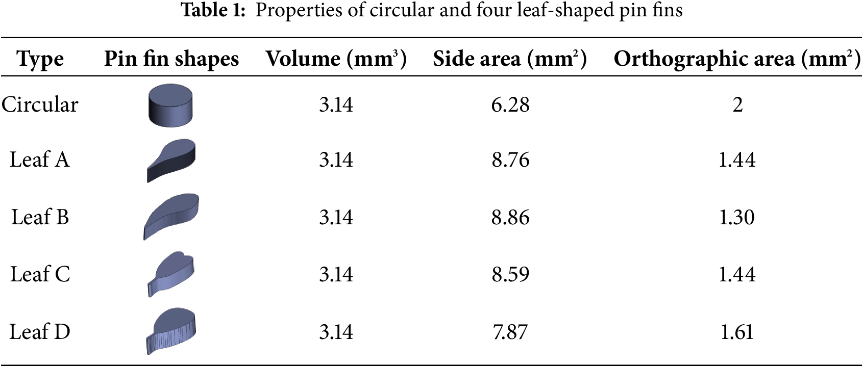
Based on the leaf shape of different leaves, we selected four typical leaf shapes as pin fin outlines. The various features of their shapes are shown in Fig. 1a,b. With the knowledge of fluid mechanics, rounded heads are often used to model low Reynolds number flows, such as low-velocity flows or highly viscous fluids. The rounded head shape reduces flow separation and vortex, resulting in lower drag and pressure loss. The Re range for this article is 40–100, so the round head was used as the upstream part. Through reverse engineering, the leaf-shape-inspired pin fins were designed on SolidWorks. The leaf outlines were stretched by 1 mm perpendicular to the leaf plane to get a single pin fin. Each pin fin has the same material properties to ensure the geometry was the only variable among different pin fins. To standardize the thermal-hydraulic performance across various leaf shapes, an equivalent total mass and pin fin base contact area were uniformly applied to the different pin fins. The diameter of the cylindrical pin fins was set at 2 mm. The properties of cylindrical and leaf-shaped pin fins are listed in Table 1.
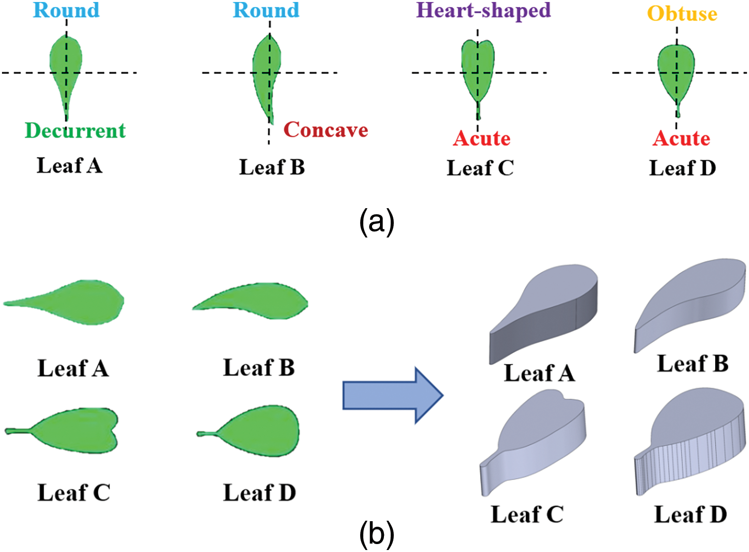
Figure 1: (a) Features of four different leaf shapes; (b) 3D single pin fins
2.2 Description of the Physical Model
As painted in Fig. 2a–c, the heat sink is of a hollow design, with the fluid entering from the inlet and flowing in a direction that is aligned and parallel to the x-axis, proceeding towards the exit. A uniform constant heat flux is used to a heating plate with an area of 40 × 20 mm2, situated at the bottom center of the rectangular channel. The pin fins were located at the middle of the rectangular tunnel, arranged in the form of a staggered arrangement. The staggered array consisted of 5 × 6 pin fins but added one pin fin in rows 2, 4, and 6. The specific parameters of the heat sink are shown in Table 2. The definitions of LASA, LBSA, LCSA, LDSA, LA-CSA, LB-ASA, LB-RBSA and LB-CSA are leaf A of staggered array, leaf B of staggered array, leaf C of staggered array, leaf D of staggered array, leaf A and leaf C of staggered array, leaf B and leaf A of staggered array, leaf B and reversed leaf B of staggered array, leaf B and leaf C of staggered array, respectively. The various configurations are shown in Fig. 3a–h.
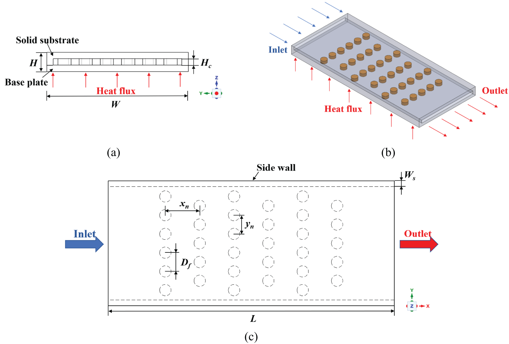
Figure 2: Staggered circular pin fin arrangement: (a) front view; (b) scenograph (c) top view
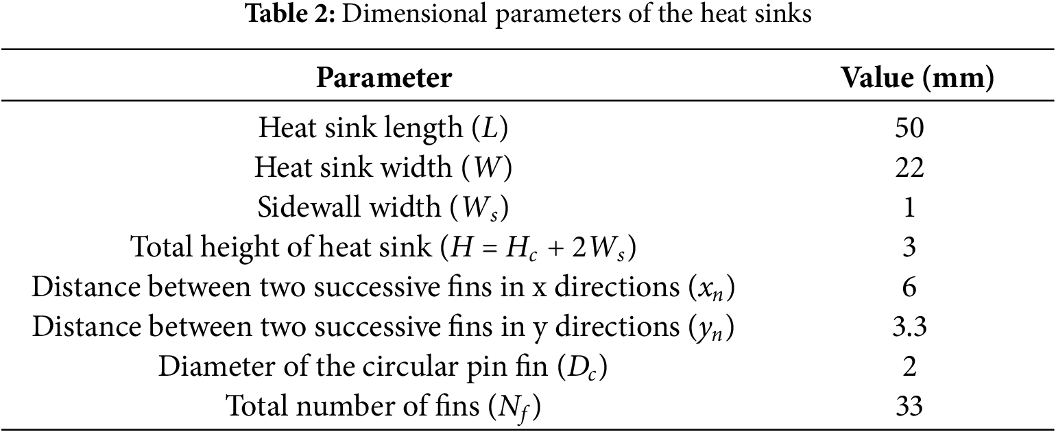
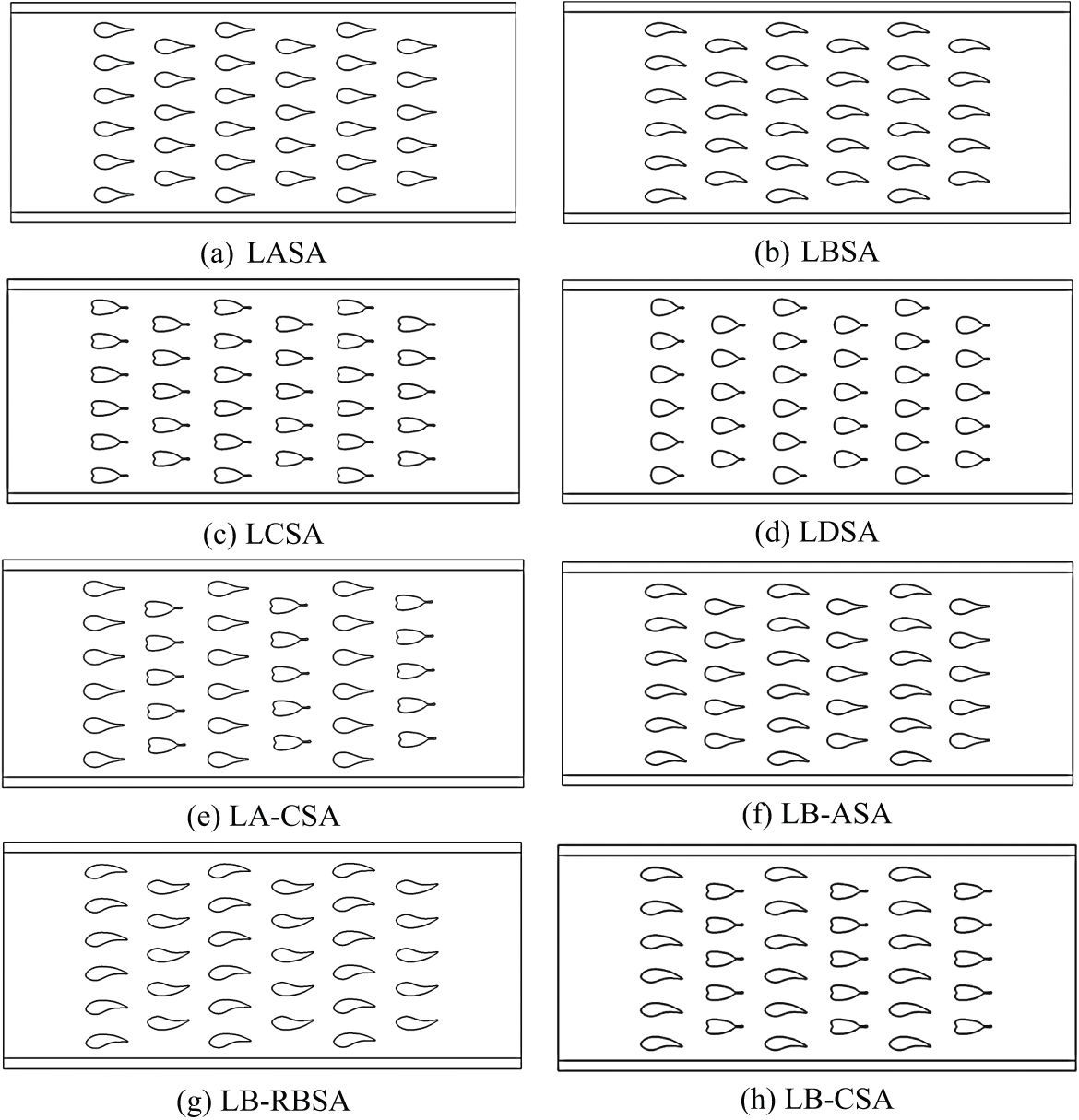
Figure 3: Leaf-shaped pin fins under the arrangement of stagger, (a) leaf A staggered array; (b) leaf B staggered array; (c) leaf C staggered array; (d) leaf D staggered array; (e) leaf A and leaf C staggered array; (f) leaf B and leaf A staggered array; (g) leaf B and reversed leaf B staggered array; (h) leaf B and leaf C staggered array
3.1 Experimental Setup and Procedure
The laboratory system shown in Fig. 4 consists of a water bath (HH-420), peristaltic pump (Longer BT600-2J), thermocouples, handheld digital pressure gauge (COMARK C9551), DC stabilized power supply (A-BF SS-605S), data acquisition instrument (KEYSIGHT 34970A) and liquid reservoir. Two rectangular channels with a length of 75 mm and a cross-section of 20 mm × 1 mm were designed as entrance and exit sections to ensure the liquid flow was fully developed. LBSA, LB-ASA, and the entrance and exit sections were printed by Muees430 which is shown in Fig. 5a. The size and material of the test section was the same as that of the numerical simulation. Fig. 5b shows the experimental setup during the test, which was covered with a foam cover during the experiment.
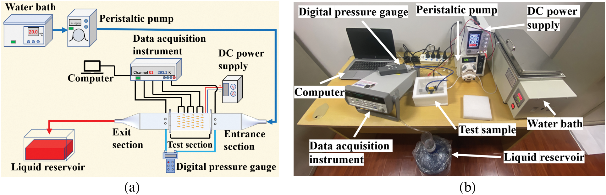
Figure 4: (a) Schematic diagram of the experimental system; (b) test equipment
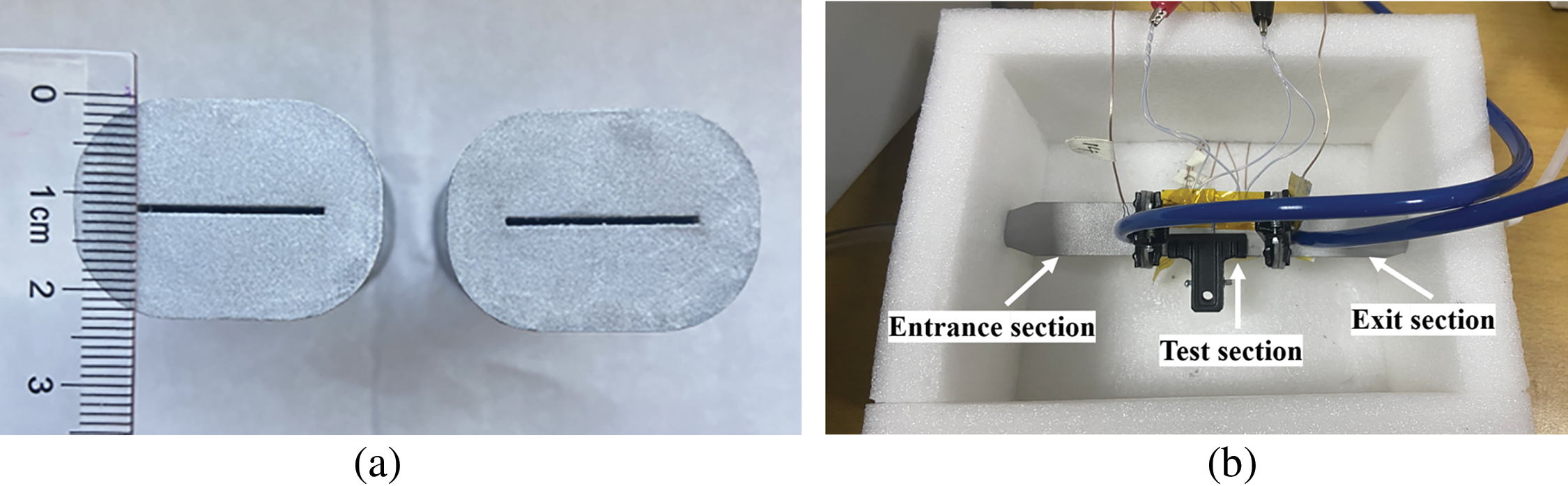
Figure 5: (a) Printed samples of LBSA and LB-ASA; (b) test samples setup
The test section was affixed to the entrance and exit sections using clips. To minimize heat transfer and avert leakage, silicone pads were employed at the interfacial surfaces between the entrance and test sections, as well as between the test and exit sections. Circular channels were reserved at the ends of the entrance section and exit section to measure the temperature and pressure at both ends of the test section. The heating block was driven by a DC power supply as a heat source. To ensure efficient heat transfer and to decrease the thermal resistance at the contact boundary, a thin layer of thermally conductive paste was applied between the test section and the heating block. Moreover, the entrance, test and exit sections were enveloped by an insulation foam box to inhibit heat loss to the circumstances.
Before the experiments, we turned on the switch on the water bath to heat deionized water to 293.1 K. Then we switched on the peristaltic pump to introduce the water into the test channel until the flow ratio of the water was steady at the lowest specified requirement. After that, we turned the DC stabilized power supply on and set the needed heating power under the constant power mode. The deionized water was heated by the water bath and then pumped by the peristaltic pump into the inlet section, the test section and the exit section, sequentially. It was considered that a stable state condition was achieved when the temperature variation on the test specimen wall was less than 0.1°C per min, which typically takes about half an hour. Following the documentation of temperature and pressure readings, we adjusted the flow ratio to a higher setting to initiate the subsequent experimental run. The procedure was consecutively executed seven times, each at varying Reynolds numbers, ranging from 40 to 100. In the same sample under different Re and among different samples, the heating power was all set to 50 W.
3.2 Uncertainty Analysis and Accuracy of the Measurement
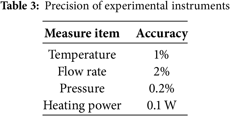
Ensuring the precision of results is of paramount importance in experimental research. Thus, uncertainty analysis of nondimensional parameters such as Nu number, friction factor was conducted according to the ANSI/ASME measurement standard [23,24]. Uncertainties in the specified nondimensional parameters were derived by utilizing dimensional parameters within the measurement methodology [25], the corresponding calculation formula is shown in Eqs. (1)–(3). The accuracy of each instrument is shown in Table 3. The maximum uncertainties associated with the Nu number and the friction factor were calculated to be ±4.8% and ±5.5%, respectively. Therefore, it was concluded that the experiment yielded satisfactory results in terms of repeatability.
4.1 Governing Equations and Boundary Conditions
Heat transfer within a pin fins heat radiator involves a sophisticated three-dimensional interplay of fluid dynamics, mass transport, and thermal processes. For its complexity, the analysis was simplified based on the following assumptions:
1. single-phase, incompressible laminar flow;
2. negligible effect of gravity and heat dissipation caused by viscosity;
3. natural convection, radiation, volume force, and surface tension are all neglected.
With these assumptions, the 3D steady-state equations governing the conjugate heat transfer can be expressed as:
Continuity equation,
Conservation of momentum,
The energy equation for the coolant,
The energy equation for the solid region,
where ρf is the density of the coolant (kg/m3), P is the average pressure (Pa), cp is the specific heat of fluid (J/kg · K), and kf is the thermal conductivity of the coolant (W/(m · K)).
Channel inlet: velocity inlet,
Channel outlet: pressure outlet,
where u, v, and w are the velocities of the x, y, and z directions based on the average of time, respectively.
Coolant-solid interface,
where Tf and Ts are the interface temperature of the liquid and solid, kf and ks are the thermal conductivity of the liquid and solid, respectively. n is the normal direction to the surface, pointing in the direction of the temperature increase.
The bottom wall of the heat radiator,
Other solid-walls,
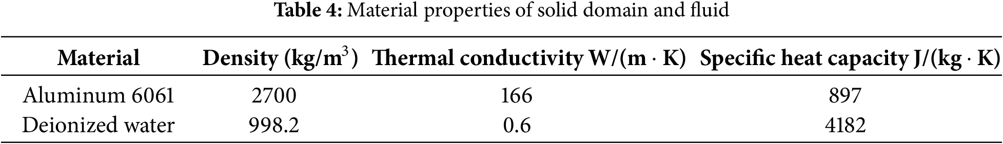
The material of the solid domain was chosen as aluminum 6061 and the deionized water was selected as the coolant. The material properties are listed as below in Table 4.
In the numerical simulations, ANSYS Fluent, a general-purpose computational fluid dynamics software utilizing the finite volume method, was employed. The governing equations were discretized on an unstructured mesh, which allowed for a more flexible and accurate representation of the complex flow domain. In the context of a multitude of flow scales, Kumar et al. [26] encapsulated that for Reynolds numbers less than 1500, the flow within the channel remained laminar. The scale of Re number in this study is from 40 to 100, therefore the laminar flow was used in simulation of models. The convergence criteria for momentum, continuity, and energy were set at 10−5, 10−6, and 10−8, respectively [8,27].
4.2 Mesh Generation and Independence Verification
The models were meshed primarily with hexahedra and supplemented with tetrahedra using Fluent Meshing to enhance computational efficiency and accuracy. In addition, the model incorporated localized encryption around the pin fin and a boundary layer partition.
The grid number of circular pin fins heat sink model were from 1,883,909 to 11,175,218. The grid number of 11,175,218 was chosen as the reference mesh number. The comparison of pressure drops and peak temperature in the circular pin fins channel was examined when Re number was 40. Fig. 6 shows that the calculation results of the mesh number of 7,421,162 is not far from the reference. Therefore, 7,421,162 was picked as the grid number. Fig. 7a–c shows the results of the meshing circular pin fins configuration.
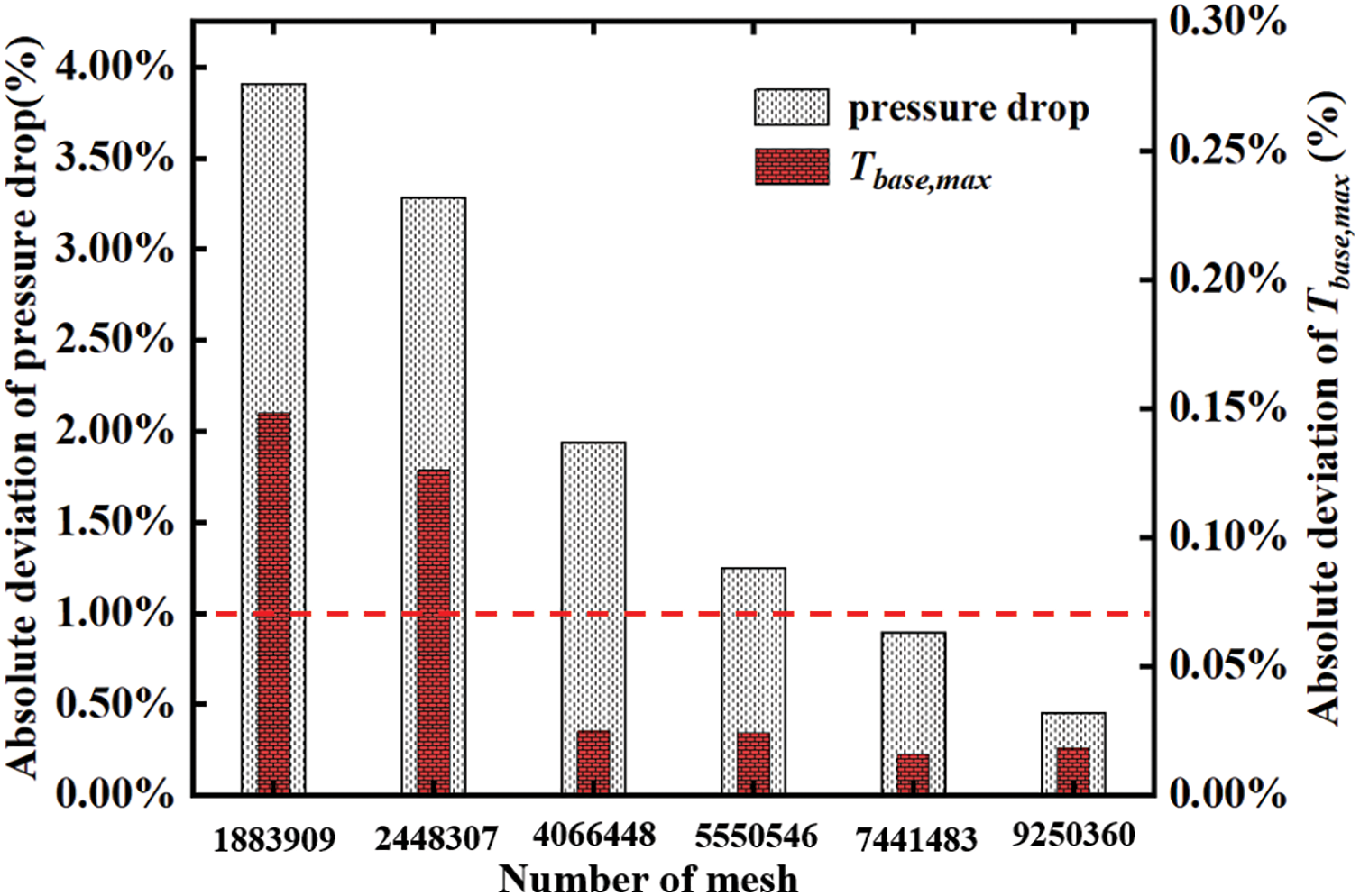
Figure 6: Effects of mesh number on results of circular pin fins model [28]
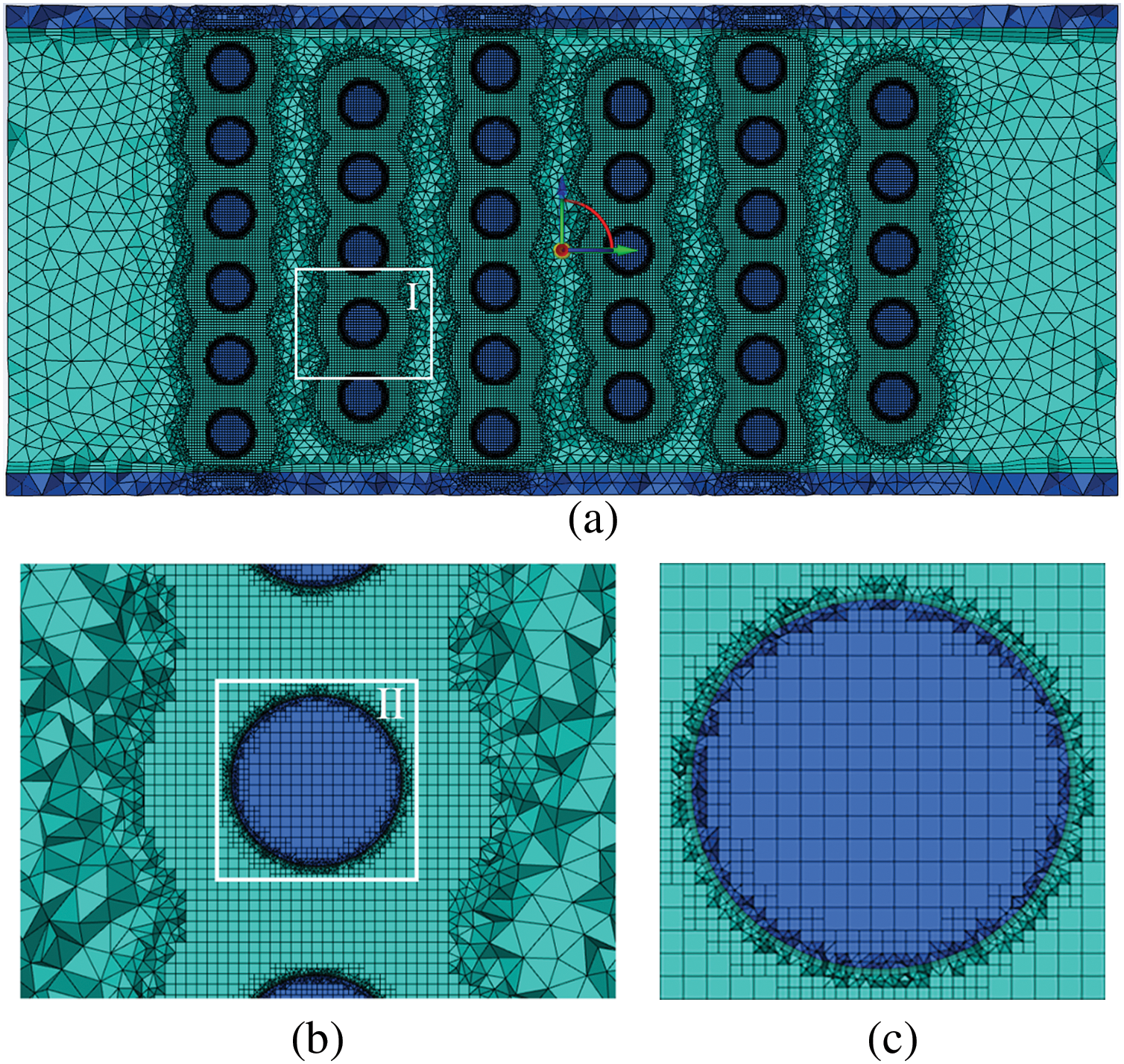
Figure 7: Illustration of Mesh for circular pin fins configuration, z = 1.5 mm: (a) the entire rectangular domain; (b) a detailed rectangular view of Section 1; (c) a detailed rectangular view of Section 2
The Reynolds number at the channel inlet is determined using the equation below:
where uin is the average velocity of the coolant at the entrance of the heat sink, Dh is the hydraulic diameter of the heat sink, μf is the dynamic viscosity of the coolant.
The friction factor [29] is calculated as:
where Δp is the pressure drop between the entrance and exit section of the heat sink, L is the length of heat sink.
The convective heat transfer coefficient and Nusselt number are calculated using the following formulas [30]:
where As is the surface area of the heat sink, Tb is the temperature of the base plate.
where Ain denotes the inlet area of the heat sink.
The thermal-hydraulic performance, often denoted as TPI, is evaluated based on a thermal performance index that enca psulates both heat conduction and fluid friction features [31,32]. The outcomes obtained from the circular pin fin configuration serve as a benchmark for comparative analysis with other pin fins geometries:
where fcir,base and Nucir,base are the friction factor and Nu of the circular pin fins array, respectively.
This part is presented in the following order. First, the reliability of the test instruments is validated by comparing the friction factor and overall Nu number of LBSA and LB-ASA experimentally and numerically. This is followed by examining the fluid flow mechanism and heat transfer features in each leaf-shaped pin fins heat sink by using numerical simulation. Finally, the test heat sinks are compared from the aspect of the TPI.
To substantiate our bionic concepts, two channels featuring leaf-shaped pin fins channel were fabricated for experimental validation. The experimental results of friction factor and Nu number for the two leaf-shaped pin fins arrays are shown in Fig. 8. A strong agreement was found between the experimental data and the simulation outcomes, thereby instilling confidence in our testing apparatus and methodologies.
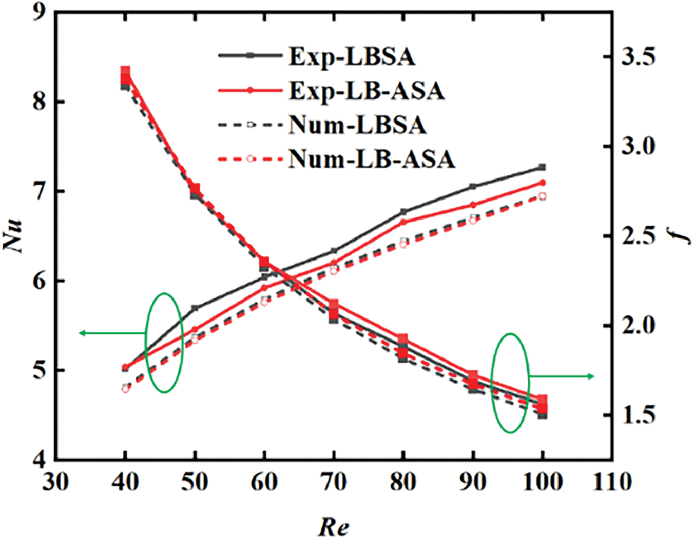
Figure 8: Test and simulation results of LBSA and LB-ASA
In the realm of thermal engineering applications, the integral efficiency of heat transfer is of utmost significance. The experimental results of Nu number for LBSA and LB-ASA in the entire tested Re range are shown in the left axis of Fig. 8. Obviously, between the two structures, the LBSA channel had the better heat transfer enhancement. The highest deviation of the measured temperature in the experiment compared to the simulation is 1.54%. The Nu number of the experiment is a little higher than that of the simulation on both models, which may be attributed to the enhanced heat transfer of the rough surface of the additive manufacturing.
For the friction factor, the LBSA configuration had a little lower friction factor compared to LB-ASA. The highest deviation of Δp in the experiment compared to the simulation is 4.17%.
Pressure drops based on the difference between the entrance and exit plane, which was calculated using the mass-weighted average pressure in the channel, changing with Re number are compared in Fig. 9a,b. The LBSA, which has the smallest pressure drop and friction coefficient in Fig. 9a, is used as the benchmark in Fig. 9b to compare the other four combinations. Obviously, pressure drop increases with increasing Re number. In addition, as the Re number increases, the pressure drop in the cylindrical pin fins channel increases more than that in the leaf-shaped pin fins channel. At lower Re numbers, the difference in pressure drop between these four structures is small. But at higher Re numbers, the difference in pressure drop is significant, which is apparently due to larger disturbances. When Re is 40, the pressure drop of the circular channel can reach up to 1.35 times LBSA, and 1.23 times LDSA. When Re is 100, the pressure drop of the circular channel can reach up to 1.56 times LBSA, and 1.35 times LDSA. Among the four base biomimetic pin fin channels, the pressure drop of LBSA is the smallest, and it is about 63.9%–74.3% of cylindrical pin fins. Among the four combinations of leaf-shaped pin fins channels, LB-RBSA shows the best performance in pressure drop, which is similar to LBSA.
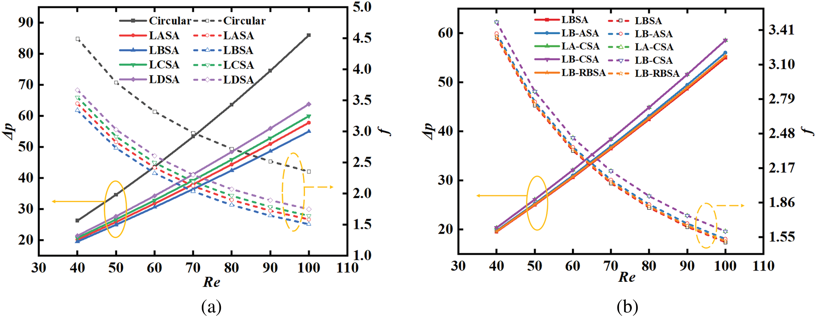
Figure 9: Pressure drops and friction factors vs. Re numbers: (a) four different leaf-shaped configurations; (b) four different combinations of leaf-shaped configurations
The variation of the friction factor with respect to the Re number is depicted in Fig. 9a,b. The friction factor diminishes with the rise in Re number. The decrease in friction factor is due to the increase in flow kinetic energy per unit volume outpacing the pressure drop. As the Reynolds number grows, the rate of decline in the friction factor slows down.
The intersection points of each channel in Fig. 9 are critical as they represent the optimal balance between pressure drop and friction coefficient in the fluid flow within the system. These points are where the trade-off between energy loss due to friction and the pressure required to drive the flow is minimized. This balance is crucial for the efficient design of heat exchangers.
When Re number is 80, Fig. 10a–i describes the velocity distribution in the central x-y plane of the channel, focusing on the flow patterns and configurations of both circular and leaf-shaped pin fin arrays. The LBSA shows that the friction factor is reduced by about 33.3% compared to the cylinder pin fins array. It may be due to the outline of the pin fin in the LBSA being more streamlined, which reduces the flow resistance. The more streamlined droplet pin fins delay or inhibit separation as the fluid passes through, which is the primary mechanism for reducing pressure drops. The reduction in friction factor can also be attributed to the LBSA’s reduced frontal area compared to cylindrical pin fins, which guides the fluid along a less convoluted path, leading to a decrease in pressure drop. Contrastingly, LASA, LCSA, and LDSA configurations feature larger frontal areas, which increase the surface area available for fluid interaction. The increased flow resistance stems from the greater drag force the fluid encounters when facing a larger obstacle. The larger frontal area also leads to more pronounced turbulence and eddies, particularly in the edge layer near the solid face, further contributing to the pressure drop. Consequently, these configurations exhibit higher pressure drops compared to designs with LBSA.
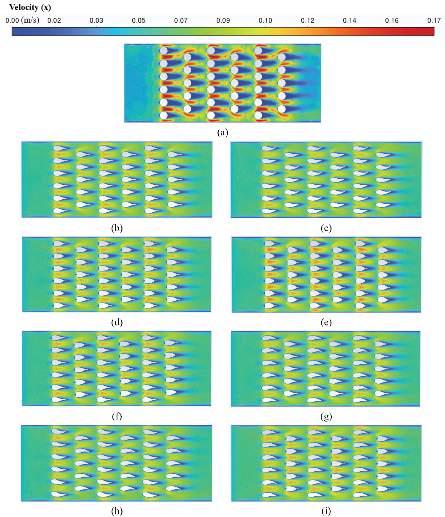
Figure 10: Velocity contours in the middle plane of the channel for Re = 80 (z = 1.5 mm). (a) circular; (b) LASA; (c) LBSA; (d) LCSA; (e) LDSA; (f) LA-CSA; (g) LB-ASA; (h) LB-RBSA; (i) LB-CSA
Fig. 11a–i shows the velocity streamline distribution of different channels for Re = 80. It is evident that there is significant flow separation occurring along the surface of the column. Acceleration occurs when the flow contacting with both the circular pin fin and leaf-shaped pin fins. As the fluid accelerates over the fin surfaces, the pressure decreases due to the conversion of potential energy into kinetic energy, assuming negligible changes in height. The fluid continues to move forward at the edge of the cylinder pin fins. When it passes the highest point of the edge of the pin fins, the fluid will decelerate and generate backpressure. At this moment, the fluid point of movement must not only resist the viscous effect, but also overcome the pressure difference. When the momentum is not enough to overcome these two effects, stagnation or even reflux will occur. The reflux will cause the fluid particles in the boundary layer to squeeze outward, thus causing the boundary layer to break away from the wall. Similarly, for leaf-shaped pin fins, there is also backpressure after the highest point, but because the outline of the rear parts of the pin fins tends to be flattened, the backpressure for the LBSA is significantly lower compared to the cylindrical pin fins. This phenomenon is even more pronounced on LBSA. There will be less kinetic energy for the reflow of the fluid mass point, so the separation point of the boundary layer of leaf-shaped pin fins are relatively backward and the thickness is relatively small. The leaf-shaped pin fins’ streamlined design minimizes boundary layer separation, leading to lower pressure drop compared to cylinder pin fins in heat exchangers.
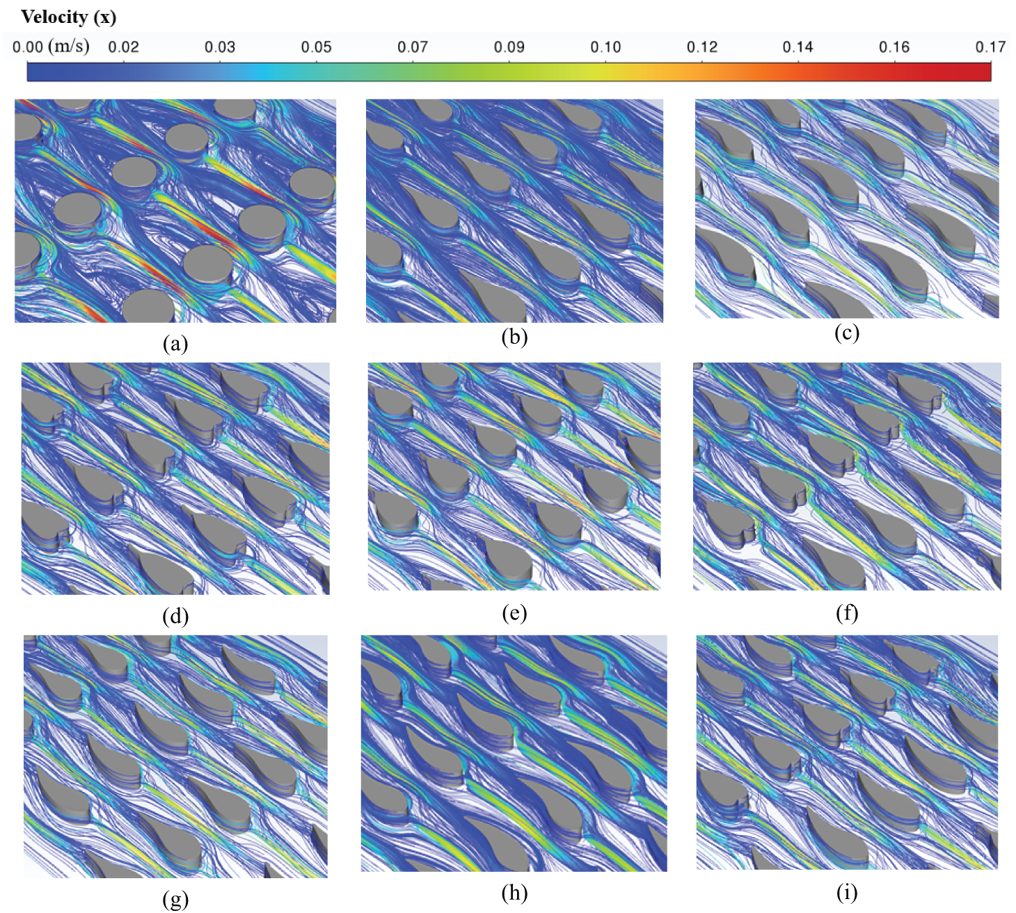
Figure 11: Velocity distribution in the middle plane of the channel for Re = 80. (a) circular; (b) LASA; (c) LBSA; (d) LCSA; (e) LDSA; (f) LA-CSA; (g) LB-ASA; (h) LB-RBSA; (i) LB-CSA
The LBSA has a minimal frontal area, and combined with its streamlined tail, allows for minimal obstruction to fluids. Although LASA and LCSA have the same frontal area, the rounded head of LASA is more conducive to the passage of the fluid, while the heart-shaped head of LCSA has a certain obstruction effect on the coolant, and the anterior part of pin fins in Fig. 11d has a more pronounced area of fluid stagnation than in Fig. 11b. The windward area of LDSA is large, and the head is blunt. The fluid produces greater resistance when flowing around the pin fins. In all four combinations, the LB-RBSA has the same windward area as the LBSA, and the simulation results are proximity to those of the LBSA. Others, as expected, did not decrease in terms of pressure drop.
A comparison of Tbase,av between leaf-shaped pin fins configurations and circular pin fins array is illustrated in Fig. 12. As depicted in Fig. 12a, the Tbase,av of four leaf-shaped pin fins arrangements is lower than that of the cylindrical throughout the Re number range. the difference of temperature between the four leaf-shaped pin fins is very small. Similarly, the contribution of the four combinations in Fig. 12b to the reduction of temperature is almost negligible. Obviously, the base plate’s average temperature drops with increasing Re number, but the decreasing trend is gradually slowing down. When the Re number is 40, the LBSA is 0.89 K lower than that of the cylinder pin fins arrangement. With the increasing of Re number, the difference of the average temperature of the base plate between leaf-shaped pin fins array and circular pin fins array gradually decreases. This may because the improvement in heat transfer efficiency due to the increase in heat transfer area of leaf-shaped pin fins arrays is gradually overtaken by the enhancement in heat conduction efficiency due to the vortex induced by the tail of circular pin fins array.
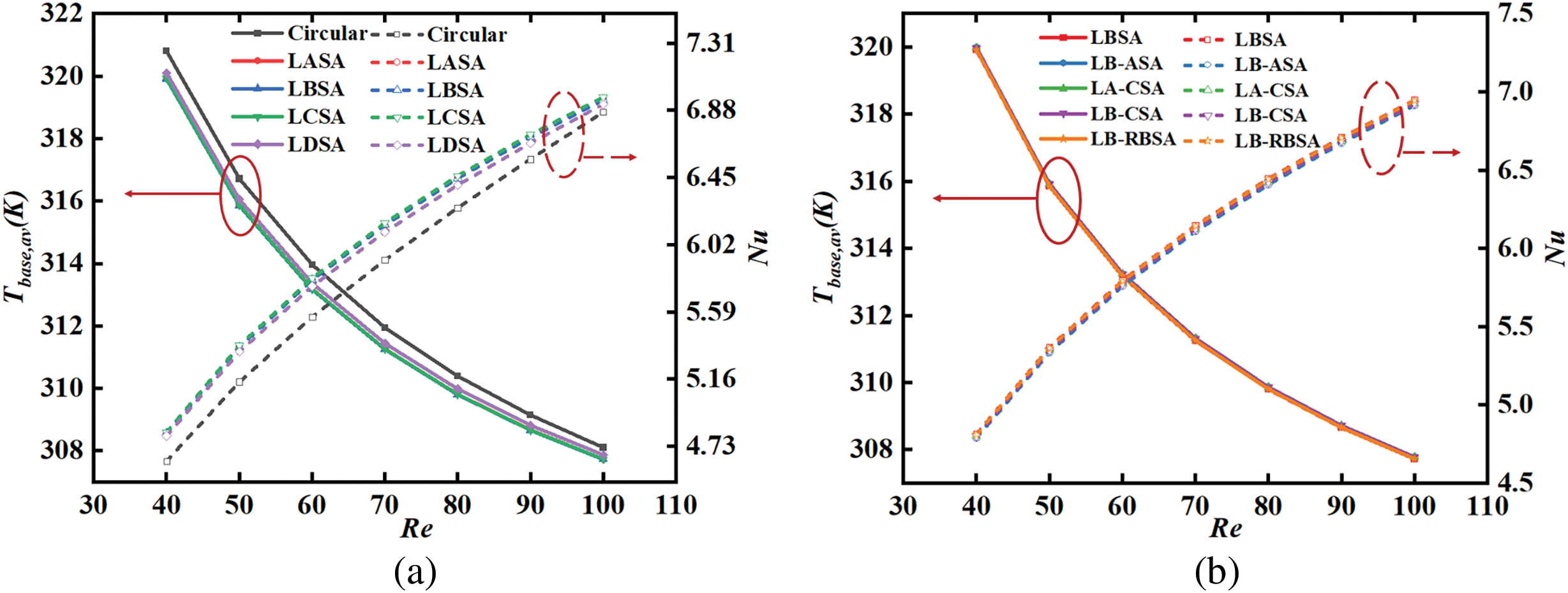
Figure 12: Tbase,av and Nu vs. Re numbers: (a) four different leaf-shaped configurations; (b) four different combinations of leaf-shaped configurations
Fig. 13a–i displays the temperature contours of base plate and pin fins in different models. It is obvious that the highest temperature occurs near the last row of pin fins. This may be since as the fluid flows through pin fins array, it experiences a deceleration effect, particularly in the regions near the last row of fins. This deceleration, or flow stagnation, leads to a buildup of fluid particles, which in turn reduces the local convective heat transfer factor. The growth of thermal boundary layer is another critical factor. As the coolant flows over the pin fins, thermal boundary layer grows in thickness, reducing the heat transfer rate. As the fluid encounters the final row of fins, the boundary layer thickens, diminishing the heat transfer coefficient and resulting in elevated temperatures. The fluid-fins surface interaction is a substantial factor as well. The heat conduction from the fins surface to the fluid is a function of the fin geometry, material, and the fluid’s properties. The last row of pin fins may have a different interaction due to the wake effect caused by the preceding fins, which can lead to a reduction in the local heat transfer coefficient and an increase in temperature. The cylindrical pin fins array exhibits the highest maximum temperature. The maximum temperature of LBSA, LASA, and LB-RBSA are 0.72, 0.71, and 0.69 K lower than the cylindrical pin fins array when Re = 80.
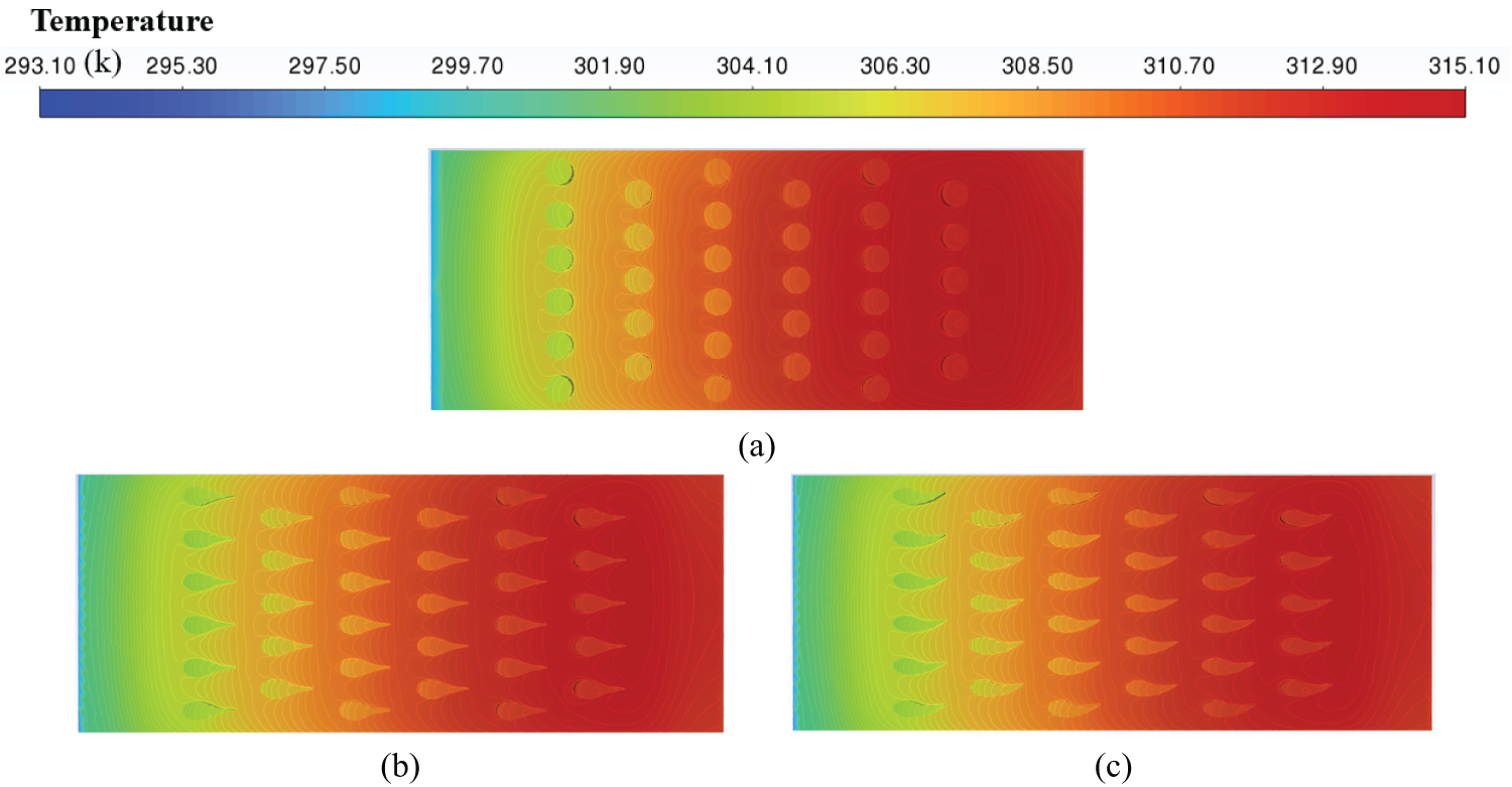
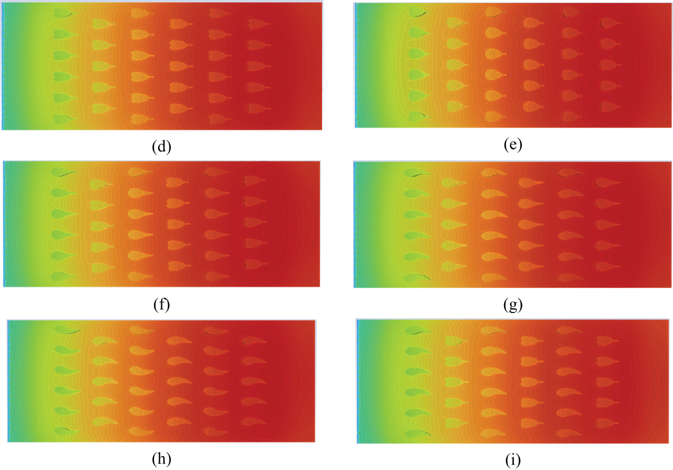
Figure 13: Temperature contours of the base plate and pin fins for different models at Re = 80, (a) circular; (b) LASA; (c) LBSA; (d) LCSA; (e) LDSA; (f) LA-CSA; (g) LB-ASA; (h) LB-RBSA; (i) LB-CSA
5.4 Thermal-Hydraulic Performance Index (TPI)
Fig. 14 shows TPI based on the cylinder pin fins array. The TPIs of all leaf-shaped pin fins arrays in this study are better than that of cylindrical configuration at the range of Re from 40–100. The TPI peaks with increasing Re number. At low Re values, an increase in the ratio of the Nu number of the leaf-shaped pin fins channel to the cylindrical channel, together with a decrease in the friction factor with the cylindrical channel, leads to an increase in TPI. As Re number increases, the ratio of the leaf-shaped pin fins channel to the cylindrical channel Nu number begins to decrease, and although the ratio of the friction factor to the cylindrical heat sink continues to decrease, the decrease of ratio to the cylindrical channel Nu number prevails, and the TPI shows a decreasing trend. Among the leaf-shaped pin fins, the LBSA configuration has the highest TPI over the whole tested Re range, which is followed by LB-RBSA, LB-ASA, LASA, LA-CSA, LB-CSA, LCSA, and LDSA configurations, respectively.
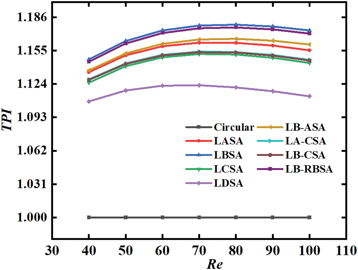
Figure 14: TPI for different models compared with circular pin fin configuration
In this paper, heat exchangers inspired by leaf shapes are conceptualized and their efficacy as solid-to-water heat exchangers is scrutinized through both numerical and experimental means. An initial experimental inquiry is executed on two channels featuring leaf-shaped pin fins to substantiate the numerical models. Subsequently, the numerical model is engaged to conduct conjugate-heat-transfer simulations encompassing additional leaf-shaped pin fins channels alongside a circular pin fins channel. The simulations provide insights into the flow and heat transfer features, which are dissected based on the outcomes of the numerical studies. It should be acknowledged that the surface of the printed cooling channel is not smooth, which will have some effect on the experimental results. Future studies could explore post-processing techniques such as electrochemical polishing. A synthesis of the findings from both the experimental and numerical studies is delineated as follows:
1. Leaf-shaped pin fins configurations possess great potential to reduce pressure drop, especially in high Re numbers. LBSA, LB-RBSA, and LASA which have round-head constructions, are more effective in reducing pressure drop. Within the Re range of 40–100, LBSA shows an average pressure drop reduction of 31.33% compared to the circular pin fins channel.
2. Under the condition of the same base area of heat dissipation fins, leaf-shaped pin fins have a better heat dissipation effect. The streamlined shapes of the leaf-shaped pin fins channel result in reduced boundary layer flow separation along the surfaces, thereby enhancing their capacity for heat rejection in comparison to the heat exchanger with circular pin fins.
3. When Re = 80, a peak TPI of 1.18 was noted for the LBSA with respect to the cylinder pin fins configuration. The amalgamation of various leaf-shaped pin fins array did not lead to a notable increase in TPI.
4. Overall, the leaf-shaped pin fins configurations studied in this paper are more efficient than cylindrical pin fins configurations, achieving TPI values above one across the tested Re numbers.
Due to time and effort constraints, we have only studied four-leaf types of pin fins. There may still exist leaf profiles in nature with better streamlining and heat dissipation capability that can be used by people in future heat dissipation projects.
Acknowledgement: The authors thank Qinghai Zhao for his help conducting the experiments.
Funding Statement: This work is supported by the Shandong Provincial Natural Science Foundation, China (Grant ZR2024ME136).
Author Contributions: The authors confirm contribution to the paper as follows: study conception and design: Chao Zhang, Qinghai Zhao; data collection: Chao Zhang, Runze Yan; analysis and interpretation of results: Chao Zhang, Runze Yan, Qingheng Tang, Honghui Li; draft manuscript preparation: Chao Zhang, Runze Yan, Qingheng Tang, Honghui Li. All authors reviewed the results and approved the final version of the manuscript.
Availability of Data and Materials: The data are available from the corresponding author upon reasonable request.
Ethics Approval: Not applicable.
Conflicts of Interest: The authors declare no conflicts of interest to report regarding the present study.
References
1. Li ZX, Sheikholeslami M, Jafaryar M, Shafee A, Chamkha AJ. Investigation of nanofluid entropy generation in a heat exchanger with helical twisted tapes. J Mol Liq. 2018;266:797–805. doi:10.1016/j.molliq.2018.07.009. [Google Scholar] [CrossRef]
2. Zhai YL, Xia GD, Li ZH, Wang H. Experimental investigation and empirical correlations of single and laminar convective heat transfer in microchannel heat sinks. Exp Thermal Fluid Sci. 2017;83:207–14. doi:10.1016/j.expthermflusci.2017.01.005. [Google Scholar] [CrossRef]
3. Mohebbi R, Mehryan SAM, Izadi M, Mahian O. Natural convection of hybrid nanofluids inside a partitioned porous cavity for application in solar power plants. J Therm Anal Calorim. 2019;137(5):1719–33. doi:10.1007/s10973-019-08019-9. [Google Scholar] [CrossRef]
4. Wang XH, Gao X, Bao KL, Hua C, Han XH, Chen GM. Experimental investigation on the temperature distribution characteristics of the evaporation section in a pulsating heat pipe. J Therm Sci. 2019;28(2):246–51. doi:10.1007/s11630-019-1065-0. [Google Scholar] [CrossRef]
5. Zhou T, Chen BC, Liu HL. Study of the performance of a novel radiator with three inlets and one outlet based on topology optimization. Micromachines. 2021;12(6):594. doi:10.3390/mi12060594. [Google Scholar] [PubMed] [CrossRef]
6. Bahiraei M, Jamshidmofid M, Goodarzi M. Efficacy of hybrid nanofluid in a new microchannel heat sink equipped with both secondary channels and ribs. J Mol Liq. 2019;273:88–98. doi:10.1016/j.molliq.2018.10.003. [Google Scholar] [CrossRef]
7. Wei LS, Liu HL, Tang CG, Tang XP, Shao XD, Xie GN. Investigation of novel type of cylindrical lithium-ion battery heat exchangers based on topology optimization. Energy. 2024;304:131886. doi:10.1016/j.energy.2024.131886. [Google Scholar] [CrossRef]
8. Yan YF, Zhao T, He ZQ, Yang ZQ, Zhang L. Numerical investigation on the characteristics of flow and heat transfer enhancement by micro pin-fin array heat sink with fin-shaped strips. Chem Eng Process-Process Intensif. 2021;160:108273. doi:10.1016/j.cep.2020.108273. [Google Scholar] [CrossRef]
9. Qu W, Mudawar I. Experimental and numerical study of pressure drop and heat transfer in a single-phase micro-channel heat sink. Int J Heat Mass Transfer. 2002;45(12):2549–65. doi:10.1016/S0017-9310(01)00337-4. [Google Scholar] [CrossRef]
10. Axtmann M, Poser R, Von Wolfersdorf J, Bouchez M. Endwall heat transfer and pressure loss measurements in staggered arrays of adiabatic pin fins. Appl Therm Eng. 2016;103:1048–56. doi:10.1016/j.applthermaleng.2016.04.066. [Google Scholar] [CrossRef]
11. Tahat M, Kodah ZH, Jarrah BA, Probert SD. Heat transfers from pin-fin arrays experiencing forced convection. Appl Energy. 2000;67(4):419–42. doi:10.1016/S0306-2619(00)00032-5. [Google Scholar] [CrossRef]
12. Zhao J, Huang SB, Gong L, Huang ZQ. Numerical study and optimizing on micro square pin-fin heat sink for electronic cooling. Appl Therm Eng. 2016;93:1347–59. doi:10.1016/j.applthermaleng.2015.08.105. [Google Scholar] [CrossRef]
13. Chyu MK, Yen CH, Siw S, Asme. Comparison of heat transfer from staggered pin fin arrays with circular, cubic and diamond-shaped elements. In: 52nd ASME Turbo Expo 2007; 2007 May 14–17; Montreal, QC, Canada. [Google Scholar]
14. Wang F, Zhang J, Wang S. Investigation on flow and heat transfer characteristics in rectangular channel with drop-shaped pin fins. Propuls Power Res. 2012;1(1):64–70. doi:10.1016/j.jppr.2012.10.003. [Google Scholar] [CrossRef]
15. Liu ZG, Guan N, Zhang CW, Jiang GL. The flow resistance and heat transfer characteristics of micro pin-fins with different cross-sectional shapes. Nanoscale Microscale Thermophys Eng. 2015;19(3):221–43. doi:10.1080/15567265.2015.1073820. [Google Scholar] [CrossRef]
16. Zhao HX, Liu ZG, Zhang CW, Guan N, Zhao HH. Pressure drop and friction factor of a rectangular channel with staggered mini pin fins of different shapes. Exp Therm Fluid Sci. 2016;71:57–69. doi:10.1016/j.expthermflusci.2015.10.010. [Google Scholar] [CrossRef]
17. Yu X, Woodcock C, Plawsky J, Peles Y. An investigation of convective heat transfer in microchannel with Piranha Pin Fin. Int J Heat Mass Transfer. 2016;103:1125–32. doi:10.1016/j.ijheatmasstransfer.2016.07.069. [Google Scholar] [CrossRef]
18. Jin W, Wu JM, Jia N, Lei J, Ji WT, Xie GN. Effect of shape and distribution of pin-fins on the flow and heat transfer characteristics in the rectangular cooling channel. Int J Therm Sci. 2021;161:106758. doi:10.1016/j.ijthermalsci.2020.106758. [Google Scholar] [CrossRef]
19. Lyu YS, Yu HY, Hu YH, Shu QL, Wang J. Bionic design for the heat sink inspired by phyllotactic pattern. Proc Inst Mech Eng Part C-J Mech Eng Sci. 2021;235(16):3087–94. doi:10.1177/0954406220959094. [Google Scholar] [CrossRef]
20. Xu Y, Li L, Wang JL. Experimental and numerical investigations of the thermal-hydraulic characteristics of novel micropin-fin heat sinks. Int J Heat Mass Transf. 2023;209:124079. doi:10.1016/j.ijheatmasstransfer.2023.124079. [Google Scholar] [CrossRef]
21. Hurry AS, Vafadar A, Hayward K, Guzzomi F, Rauthan K. Numerical investigation of the thermo-hydraulic performance of a shark denticle-inspired plate fin heat exchanger. Appl Therm Eng. 2024;239:122192. doi:10.1016/j.applthermaleng.2023.122192. [Google Scholar] [CrossRef]
22. Zhang FR, Huang ZK, Li SY, Sun SZ, Zhao HB. Design and thermal performance analysis of a new micro-fin liquid cooling plate based on liquid cooling channel finning and bionic limulus-like fins. Appl Therm Eng. 2024;237:121597. doi:10.1016/j.applthermaleng.2023.121597. [Google Scholar] [CrossRef]
23. Abernethy RB, Benedict RP, Dowdell RB. ASME measurement uncertainty. J Fluids Eng. 1985;107(2):161–4. doi:10.1115/1.3242450. [Google Scholar] [CrossRef]
24. Wijayanta AT, Yaningsih I, Juwana WE, Aziz M, Miyazaki T. Effect of wing-pitch ratio of double-sided delta-wing tape insert on the improvement of convective heat transfer. Int J Therm Sci. 2020;151:106261. doi:10.1016/j.ijthermalsci.2020.106261. [Google Scholar] [CrossRef]
25. Kirkup L, Frenkel RB. An introduction to uncertainty in measurement: using the GUM (guide to the expression of uncertainty in measurement). Cambridge: Cambridge University Press; 2006. [Google Scholar]
26. Kumar V, Paraschivoiu M, Nigam KDP. Single-phase fluid flow and mixing in microchannels. Chem Eng Sci. 2011;66(7):1329–73. doi:10.1016/j.ces.2010.08.016. [Google Scholar] [CrossRef]
27. Sakanova A, Tseng KJ. Comparison of pin-fin and finned shape heat sink for power electronics in future aircraft. Appl Therm Eng. 2018;136:364–74. doi:10.1016/j.applthermaleng.2018.03.020. [Google Scholar] [CrossRef]
28. Bhandari P, Prajapati YK. Thermal performance of open microchannel heat sink with variable pin fin height. Int J Therm Sci. 2021;159:106609. doi:10.1016/j.ijthermalsci.2020.106609. [Google Scholar] [CrossRef]
29. Qi C, Tu JL, Ding Z, Wang YX, Sun L, Wang CC. Experimental study on the influence of bionic channel structure on waste heat utilization equipment. Asia Pac J Chem Eng. 2021;16(5):e2668. doi:10.1002/apj.2668. [Google Scholar] [CrossRef]
30. Mohammadpour J, Salehi F, Lee A. Performance of nano encapsulated phase change material slurry heat transfer in a microchannel heat sink with dual-circular synthetic jets. Int J Heat Mass Transf. 2022;184:122265. doi:10.1016/j.ijheatmasstransfer.2021.122265. [Google Scholar] [CrossRef]
31. Hithaish D, Saravanan V, Umesh CK, Seetharamu KN. Thermal management of Electronics: numerical investigation of triangular finned heat sink. Therm Sci Eng Prog. 2022;30:101246. doi:10.1016/j.tsep.2022.101246. [Google Scholar] [CrossRef]
32. Lewis MJ. Optimising the thermohydraulic performance of rough surfaces. Int J Heat Mass Transfer. 1975;18(11):1243–8. doi:10.1016/0017-9310(75)90232-X. [Google Scholar] [CrossRef]
Cite This Article
 Copyright © 2025 The Author(s). Published by Tech Science Press.
This work is licensed under a Creative Commons Attribution 4.0 International License , which permits unrestricted use, distribution, and reproduction in any medium, provided the original work is properly cited.
 Downloads
 Citation Tools