
 Submit a Paper
 Propose a Special lssue
 Open Access
ARTICLE

Experimental Investigation of a Loop Heat Pipe with a Flat Evaporator
National Key Laboratory of Spacecraft Thermal Control, Beijing Institute of Spacecraft System Engineering, China Academy of Space Technology, Beijing, 100094, China
* Corresponding Author: Hongxing Zhang. Email:
(This article belongs to the Special Issue: Recent Advances in Loop Heat Pipe)
Frontiers in Heat and Mass Transfer 2025, 23(2), 651-662. https://doi.org/10.32604/fhmt.2025.062191
Received 12 December 2024; Accepted 19 February 2025; Issue published 25 April 2025
 View Full Text
 Download PDF
Abstract
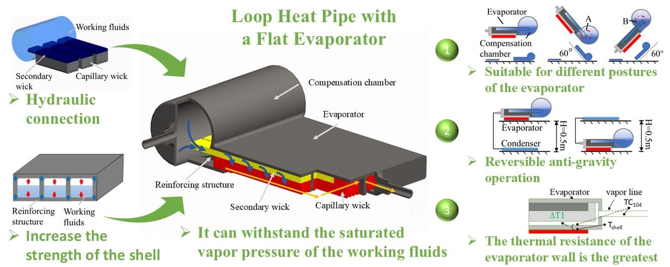
The loop heat pipe with a flat evaporator is mainly divided into two forms: rectangular evaporator and disk-shaped evaporator. The rectangular evaporator has advantages such as low heat leakage, a thin shell, and a large contact area compared to the disk-shaped evaporator. However, most of the research on rectangular evaporators focuses on working fluids such as water, methanol, and acetone, when these working fluids are in operation, the internal pressure of the evaporator is less than atmospheric pressure. Ammonia, propylene, and other working fluids can also be utilized in the loop heat pipe, these working fluids demonstrate better performance when operating within other temperature intervals, for example, the operating temperature range of ammonia is −20°C to 50°C, however, in an atmospheric pressure environment, it is very difficult for the shell of the rectangular evaporator to withstand the saturated vapor pressure of the working fluid. This paper designs a rectangular flat plate loop heat pipe that can use ammonia as the working fluid. The internal reinforcing structure is used to improve the pressure strength of the shell. The secondary wick connects the compensation chamber and the capillary wick hydraulically. The experiment indicates that this kind of rectangular evaporator is unaffected by the position, and the secondary wick can effectively supply liquid under different angles. The thermal resistance of the evaporator wall was analyzed, and it was found that the thermal resistance of the evaporator wall was the main component of the thermal resistance of the system. The heat transfer capacities of 460 W@0.5 m and 200 W@10 m were tested. The test results indicate that by setting a reinforcing structure inside the flat plate evaporator, the evaporator can withstand internal pressure. Combined with the design of the secondary wick, the flat plate evaporator can use working fluids with different pressures, expanding the range of available working fluids.Graphic Abstract
Keywords
With the miniaturization of electronic devices, the application advantages of loop heat pipe with a flat evaporator have gradually become prominent [1–3]. In addition to inheriting the advantages of traditional loop heat pipes, they have the characteristics of small size and easy installation, which has become a research hotspot in recent years [4–6]. The loop heat pipe featuring a flat evaporator mainly presents itself in two forms: disk-shaped evaporator and rectangular evaporator. Disc-shaped loop heat pipes are inevitably affected by heat leakage due to the up-down sandwich structure [7]. Therefore, Yu Maydanik and others proposed and developed a rectangular evaporator [8,9]. Because the compensation chamber is far from the heat source, the heat leak from the evaporator to the compensation chamber is small, and the rectangular evaporator is a more technically advantageous development direction than the disc-shaped evaporator [10]. In recent years, rectangular evaporators mostly use working fluids such as alcohol, acetone, and water, which are working fluids with a working pressure lower than the external atmospheric pressure. Reference [11], ammonia, propylene and other working fluids can also be employed in the loop heat pipe, these working fluids have better performance in other temperature ranges, for example, the operating temperature range of ammonia is −20°C to 50°C, the pressure of these types of working fluids at the working temperature is greater than the atmospheric pressure [12], if these types of working fluids are used in a rectangular evaporator, it is very difficult for the shell to withstand the pressure of the working fluids.
Ammonia is a commonly used heat pipe working fluid, it is widely used in traditional cylindrical evaporators. The shell of traditional cylindrical evaporators can withstand the saturated vapor pressure of ammonia. To meet the pressure requirements, a reinforced structure can be designed inside the rectangular evaporator to form a parallel form similar to a small evaporator, which can adapt to the pressure of working fluid [13,14]. However, because of the enhanced structural isolation, the parallel small evaporator will have an uneven working fluid supply [15–17]. The secondary wick can be added to the surface of the capillary wick to form a hydraulic connection between the capillary wick and the compensation chamber to achieve the purpose of a uniform working fluid supply [18].
The design of a stainless-steel ammonia loop heat pipe having a flat evaporator with a rectangular structure is presented in this paper. An internal reinforcing structure is incorporated to enhance the pressure resistance of the shell. A secondary wick is utilized to hydraulically connect the compensation chamber and the evaporator. The operating characteristics of the evaporator remain unaffected by the relative positions of the evaporator and the compensation chamber, as well as those of the evaporator and the condenser. Notably, the system maintains a heat transfer capacity of 200 W even with long-distance transmission (up to 10 m). An analysis of the thermal resistance within the system indicates that the thickness of the evaporator wall is the primary contributor to thermal resistance. The test results indicate that by setting a reinforcing structure inside the flat evaporator, the evaporator can withstand internal pressure. Combined with the design of the secondary wick, the flat evaporator can use working fluids with different pressures, expanding the range of available working fluids.
Ammonia served as the working medium in the experiment. A nickel powder capillary wick was utilized, while the shell and pipeline were constructed from stainless steel. The evaporator had a thickness of 8 mm, and the compensation chamber was cylindrical, with a diameter of 20 mm. The design parameters are shown in Table 1.
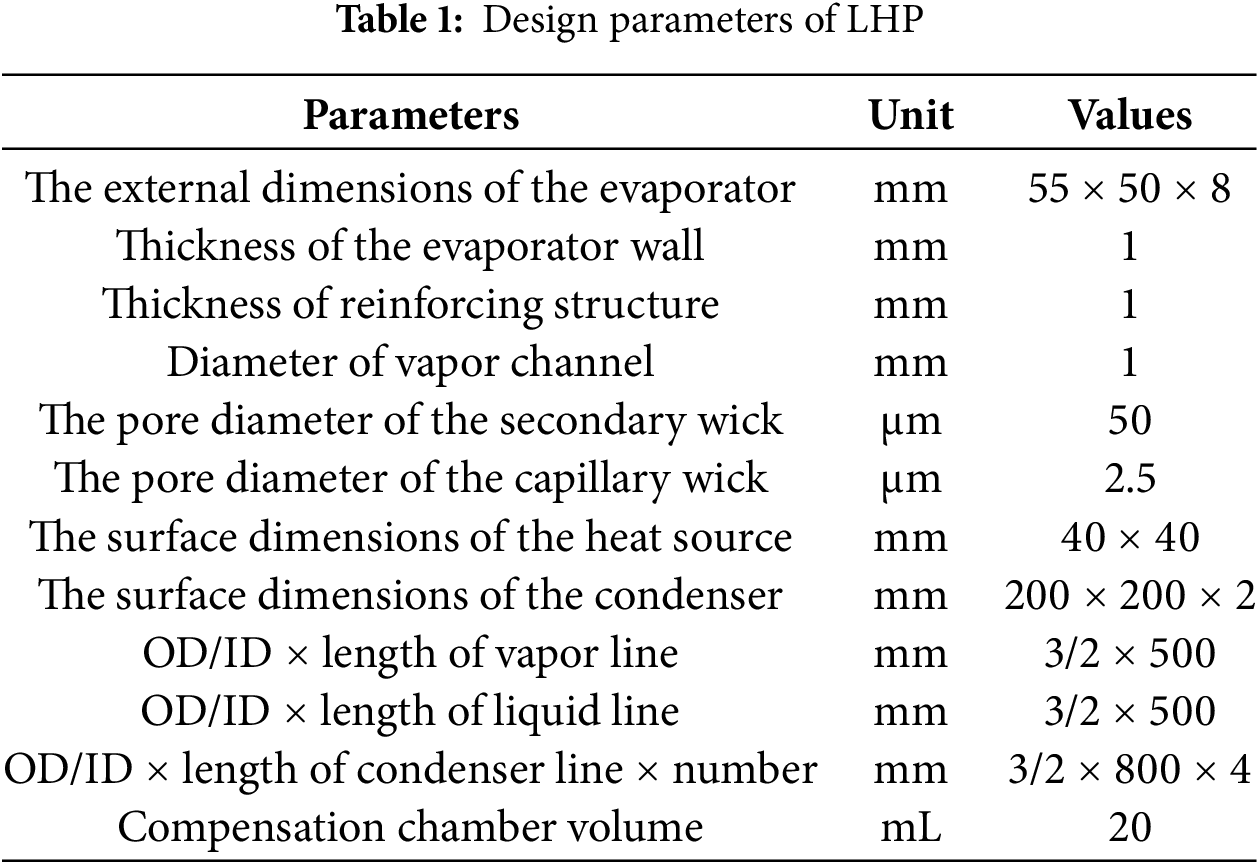
Fig. 1 illustrates the evaporator’s structural design. The compensation chamber is cylindrical and positioned on one side of the evaporator. The evaporator is equipped with internal reinforcements and features a secondary wick on the upper surface. This secondary wick extends into the compensation chamber to create a hydraulic connection. Additionally, the lower surface of the capillary wick contains vapor channels, which serve as vapor pathways for the working fluid’s phase change when the bottom of the evaporator is in contact with the heat source.
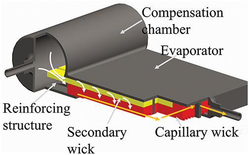
Figure 1: Internal structure of evaporator
The condenser lines are brazed onto a copper plate, as illustrated in Fig. 2. To minimize the flow resistance of the working fluid in the condenser and enhance the heat dissipation area, the design incorporates four parallel condenser lines. Each set of these condenser lines is 800 mm long.
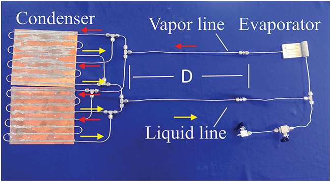
Figure 2: The test loop heat pipe
The testing equipment consists of a cooling system, a heating system, and a testing system. The cooling system includes cooling water and an aluminum cold plate with embedded microchannels. The heating system includes a power supply and a simulated heat source. The testing system includes a computer, thermometers, and thermocouples. As shown in Fig. 3a.
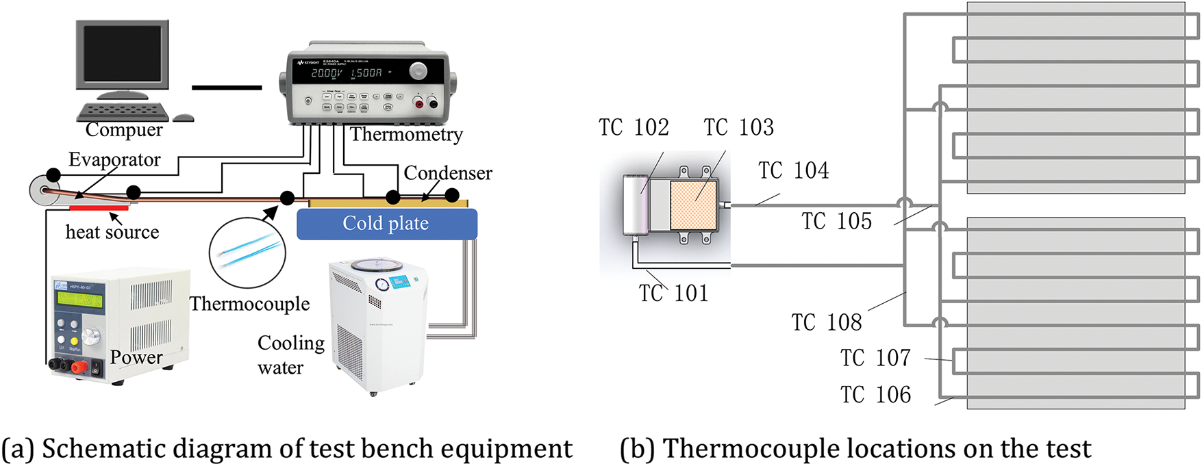
Figure 3: Schematic diagram of test bench
A temperature measurement device was utilized to collect and record temperatures at key points on the loop heat pipe. Type T thermocouples were arranged on the test sample’s shell, as illustrated in Fig. 3b. The main monitoring points include: compensation chamber inlet (TC101), compensation chamber (TC102), evaporator (TC103), evaporator outlet (TC104), condenser inlet (TC105), the temperatures of the condenser pipelines range from TC106 to TC108. The temperature measurement point in the compensation chamber is positioned above it to monitor the temperature of the two-phase fluid inside. The layout of the other points is shown in Fig. 3b, where the four parallel condenser lines are simplified to a single representation. During testing, the temperature value at the evaporator outlet (TC104) represents the operating temperature of the loop heat pipe. The power supply used in the experiment can display the set power, with an error range of ±0.5%. The temperature measurement error of the thermometer is ±0.1°C.
3 Experimental Results and Analysis
3.1 Influence of Evaporator and CC Orientation
When a loop heat pipe is operating, the liquid in the compensation chamber supplies the evaporator, ensuring stable circulation of the working fluid. The orientation of the evaporator and compensation chamber in a gravitational field affects operation in two main ways. First, when the compensation chamber is positioned higher than the evaporator and is horizontal, gravity effectively delivers liquid to the capillary wick. However, when the elevation of the evaporator is greater than that of the compensation chamber, the liquid working fluid must work against gravity to reach the evaporator, creating a more challenging situation. In this scenario, the secondary wick must assist in drawing the liquid to the capillary wick. Second, the different orientations of the evaporator and compensation chamber influence the vapor-liquid interface within the compensation chamber, which in turn affects heat leakage from the evaporator to the compensation chamber.
This study examines the loop heat pipe with a flat evaporator, focusing on the compensation chamber, which acts as the storage device for the liquid working fluid. The compensation chamber is analyzed in three different orientations: first, both the evaporator and compensation chamber are positioned horizontally; second, the evaporator is located higher than the compensation chamber; and third, the compensation chamber is positioned higher than the evaporator. Schematic diagrams illustrating these three orientations are presented in Fig. 4.
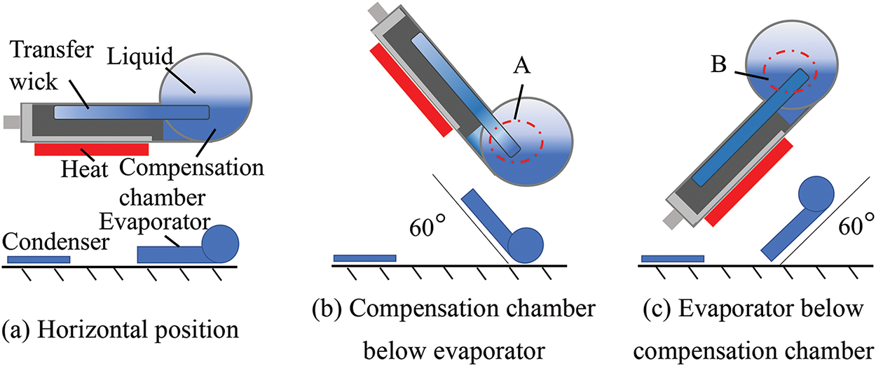
Figure 4: Orientation of evaporator and compensation chamber
In the experiments, the water-circulated refrigeration unit was set to 25°C, and various thermal loads were applied to the evaporator using a simulated heat source. We tested the working temperatures of the loop heat pipe in different orientations. The experimental temperature curves for the three orientations are displayed in Figs. 5–7. The results indicate that the loop heat pipe functioned properly in all three orientations.
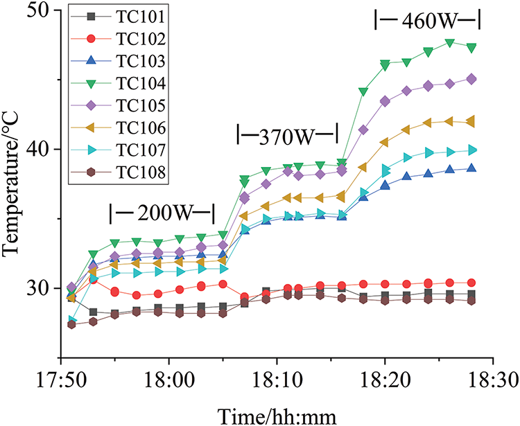
Figure 5: Test result of evaporator and compensation chamber at horizontal position
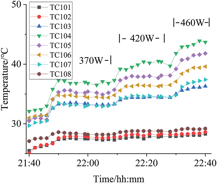
Figure 6: The test result of the evaporator is higher than the compensation chamber
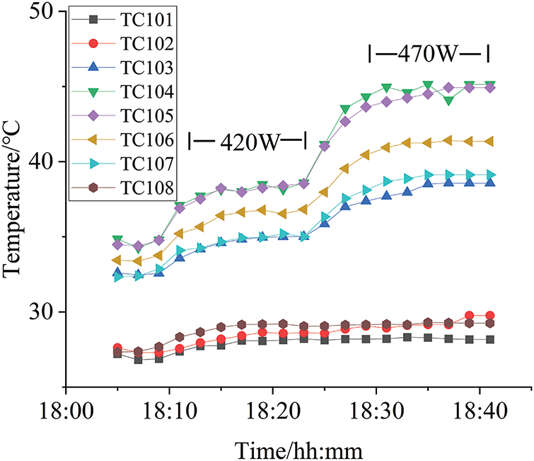
Figure 7: Test result of evaporator below compensation chamber
Fig. 5 illustrates the test result under a horizontal position. At a power level of 200 W, the working temperature remains stable. As the power increases, the system’s working temperature also rises, at 460 W, the temperature difference between TC104 and TC107 is close to 10°C. Fig. 6 presents the temperature response of the evaporator while positioned above the compensation chamber and Fig. 7 displays the result of the evaporator located below the compensation chamber. Both figures indicate that the working temperature rises with increased power, and notable temperature fluctuations occur at higher power levels. In Fig. 7, the temperatures of TC104 and TC105 are always the same, and the evaporator does not overheat. This indicates that, affected by gravity, having the compensation chamber above the evaporator is beneficial to the operation of the evaporator.
The operating temperature values of the loop heat pipe are shown in Fig. 8. When the power is 370 W, the operating temperature of the loop heat pipe in the position shown in Fig. 4c is 3°C lower than that in the horizontal position. Both the secondary wick and the capillary wick are immersed in the liquid working fluid, and this is a favorable liquid supply position at this time. When the loop heat pipe is in the position shown in Fig. 4b, only the secondary wick is immersed in the liquid working fluid. The capillary wick relies on the secondary wick to supply the working fluid, so the operating temperature of the system is slightly higher.
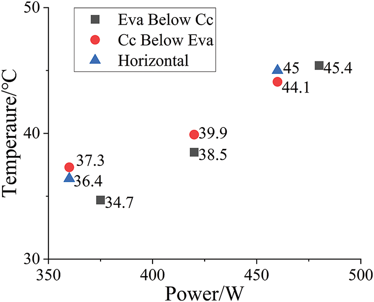
Figure 8: Comparison chart of the evaporator’s working temperatures
The experimental findings suggest that, across the three configurations that were subjected to testing, the heat transfer limits of the loop heat pipe are relatively comparable, standing at around 460 W. As the simulated heat source load increases further, the heat transfer limit of the loop heat pipe designed in this study is primarily constrained by the maximum capillary force in the evaporator. Although the operating temperatures vary slightly, all configurations can operate stably.
3.2 Influence of Evaporator and Condenser Orientation
The relative positions of the evaporator and condenser have a significant impact on the circulation flow resistance of the loop heat pipe. In the case where the evaporator is positioned at a higher elevation than the condenser, the liquid return has to overcome the gravitational force. On the other hand, if the evaporator is positioned lower than the condenser, gravity assists in returning the liquid to the evaporator. Tests on heat transfer performance and capacity limits of the loop heat pipe with a flat evaporator were conducted with these two orientations of the evaporator and condenser, as illustrated in Fig. 9.
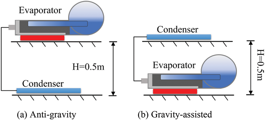
Figure 9: Orientation of evaporator and condenser
Figs. 10 and 11 illustrate the experimental temperature curves for both the anti-gravity and gravity-assisted orientations at a distance of 0.5 m. The results reveal that the heat transfer limits are 420 W for the anti-gravity orientation, 460 W for the horizontal orientation, and 475 W for the gravity-assisted orientation. The highest heat transfer capacity is achieved in the gravity-assisted orientation, while the lowest is observed in the anti-gravity orientation.
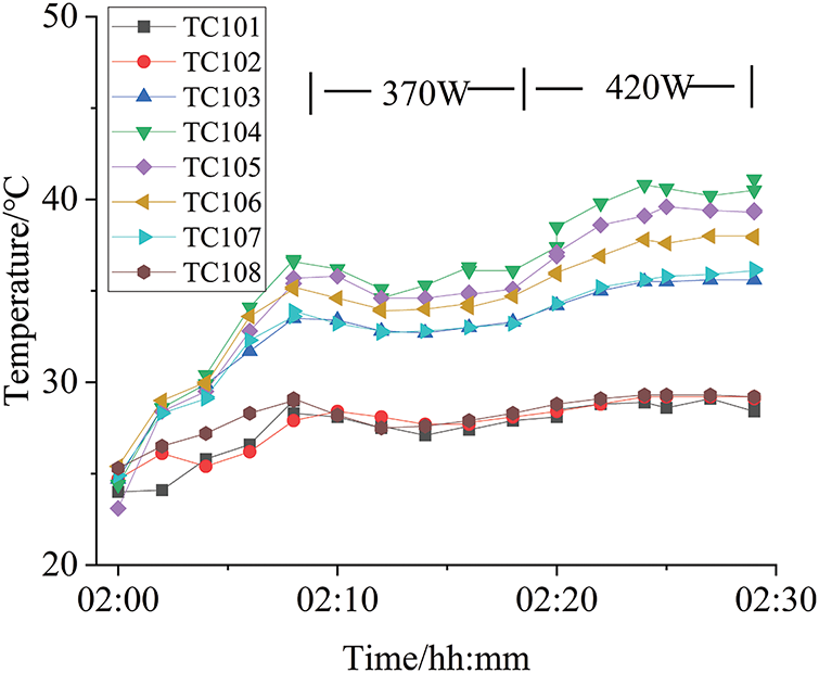
Figure 10: Test result of anti-gravity (0.5 m) orientation
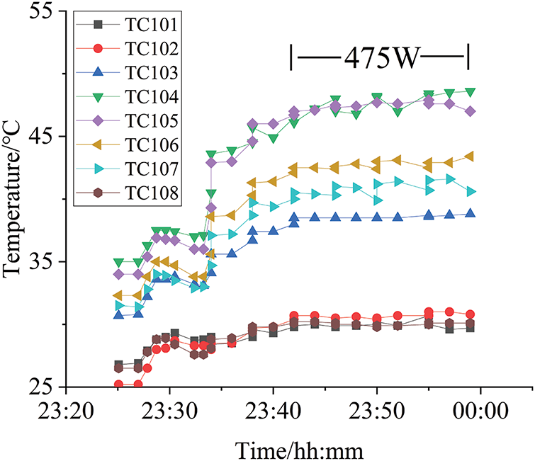
Figure 11: Test result of gravity-assisted (0.5 m) orientation
For a loop heat pipe to operate normally, the capillary driving force must be at least equal to the total resistance encountered during the circulation of the working fluid. This total resistance includes several components: the flow resistance of the liquid working fluid as it passes through the capillary wick to the evaporation surface, the resistance of the vapor flow through the vapor channels and vapor line, the flow resistance within the condenser, the resistance in the liquid line, and the pressure drop due to gravity. This relationship is expressed in Eq. (1).
In the formula:
When the capillary driving force is limited, the gravitational pressure drop can significantly affect the maximum heat transfer capability. In designing the experimental device, the surface tension of ammonia at 40°C is 0.017 N/m. The capillary force calculated according to the capillary pressure formula is 27.34 kPa. The calculation formula is ΔPc = 2 σcosθ/r, here, θ represents the contact angle, r denotes the effective pore radius, and σ stands for the surface tension. In the experiment, the gravitational height is 0.5 m. According to the calculation of ΔPg = ρ g h, the pressure difference generated by gravity is 2.9 kPa. Here, ρ is the density of ammonia at 25°C, g is the acceleration due to gravity, and h is the gravitational height, which represents about 10.6% of the total capillary driving force. As a result, the orientation against gravity decreases the maximum heat transfer capacity of the loop heat pipe.
3.3 Maximum Heat Transfer Capacity and Ultimate Heat Flow Density
To further analyze the performance of the flat evaporator, we examined the thermal resistance based on the test results from a 0.5 m transmission distance in a horizontal position. Fig. 12 illustrates the analysis of the system’s temperature difference. Below is the analysis of the system’s thermal resistance.
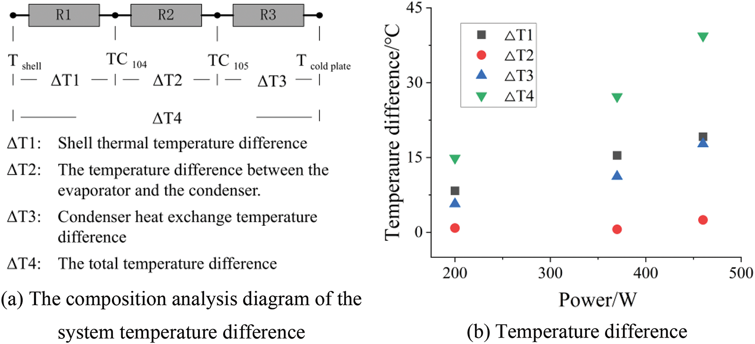
Figure 12: Temperature difference test diagram at different heat transfer power
The evaporator shell is made of stainless steel with a wall thickness of 1 mm. The temperature difference of the wall is represented by ΔT1, as the heat source is tightly adhered to the evaporator, the surface temperature of the shell cannot be measured directly. Therefore, Fourier’s formula is used to calculate the temperature difference across the shell wall thickness, the thermal conductivity of stainless steel is taken as 15 W/(m·°C), the contact area between the heat source and the evaporator is 16 cm2, at a heat load of 460 W, the wall temperature difference is 19.17°C. The wall thermal resistance of the evaporator is calculated by the formula Re = (Te − Tv)/Q, where Te is the temperature of the evaporator wall in the heating zone, and Tv is the vapor temperature at the evaporator outlet, which is the temperature of TC104, TC104 is close to the inner surface temperature, therefore, in the formula, (Te − Tv) is approximately equal to ΔT1, Q is the heat load, when the heat load is 460 W, the wall thermal resistance of the evaporator is 0.0413°C/W. ΔT2 refers to the temperature difference between the evaporator outlet at TC104 and TC105. When the heat load is 460 W, this temperature difference is 2.48°C. ΔT3 indicates the temperature difference between TC105 and the cold plate, The set temperature of the cold plate is 25°C. When the heat load is 460 W, this temperature difference is 17.73°C, the temperature differences of each part are shown in Fig. 12.
The total thermal resistance of a system including an LHP is calculated by the formula Rsys = (Tj − Tcool)/Q, (Tj − Tcool) is the total temperature difference, where Tj is the temperature at the heat source surface that is in contact with the evaporator wall, the temperature Tj is the temperature Tshell, and Tcool is the temperature of the cold plate, which is the temperature Tcold plate, as shown in Fig. 12a, the total temperature difference is the sum of ΔT1, ΔT2 and ΔT3, Q is the heat load. The total thermal resistance of the system can be calculated as follows: when the heat load is 460 W, the total temperature difference is 39.38°C and the total thermal resistance is 0.086°C/W, the thermal resistance of the evaporator wall is 0.0413°C/W, the thermal resistance of the wall accounts for 48.7% of the total thermal resistance, when the heat load is 370 W, the total temperature difference is 27.22°C and the total thermal resistance is 0.074°C/W, the thermal resistance of the wall accounts for 55.6% of the total thermal resistance, when the heat load is 200 W, the total temperature difference is 14.89°C and the total thermal resistance is 0.074°C/W, the thermal resistance of the wall accounts for 55.9% of the total thermal resistance. The thermal resistance is slightly larger when the power is 460 W, as can be seen from Fig. 12b, this is because the slopes of the curves of ΔT2 and ΔT3 increase, indicating that the system experiences overheating when the heat load is 460 W.
3.4 Influence of Transmission Distance
In order to investigate the influence of transmission distance on heat transfer performance, we conducted a retest on the loop heat pipe with a flat evaporator after extending the vapor and liquid lines to 10 m. As shown in Fig. 13, at a 10-meter distance, the maximum heat transfer capability of the loop heat pipe with a flat evaporator dropped to 200 W. Increasing the power beyond this point resulted in dry-out conditions.
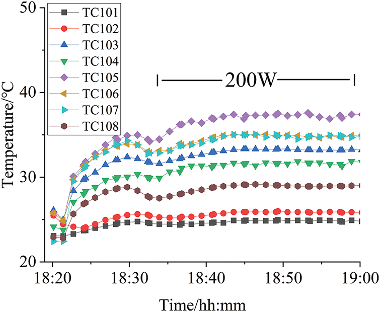
Figure 13: Test result of transmission distance of 10 m
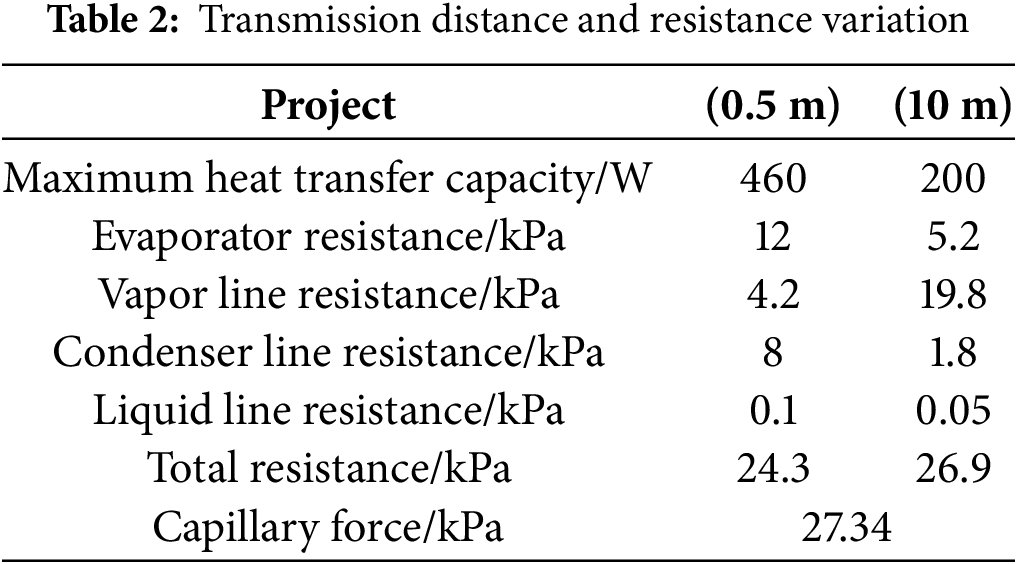
According to Darcy’s Law, the internal resistance of the evaporator is calculated based on a measured penetration rate of 1 × 10⁻¹⁴ m2. When the transmission distance is 0.5 m, the internal resistance of the evaporator accounts for 49% of the total resistance. However, when the transmission distance increases to 10 m, the internal resistance of the evaporator only accounts for 19.3% of the total resistance, indicating that its proportion becomes quite small.
According to Eq. (2), the distribution of system resistance for two experimental setups (0.5 and 10 m) has been calculated. As shown in Table 2, when the length of the vapor line is increased to 10 m, the vapor line resistance becomes the dominant component of the system resistance, accounting for 73.6% of the total resistance. In contrast, with a line length of 0.5 m, it only accounts for 17.3%. The capillary force provided by the evaporator helps to offset the resistance of the vapor line; however, this significantly reduces its maximum heat transfer capacity.
In the formula: μ—the viscosity of the working fluid, the unit is Pa·s;
This paper designs a loop heat pipe with a flat rectangular evaporator. The reinforcing structure inside the shell enables the evaporator to use working fluids with different pressures. The secondary wick can achieve a hydraulic connection between the compensation chamber and the capillary wick, although the capillary wicks are divided by the reinforcing structure, local failures will not occur. Meanwhile, it remains unaffected by the relative positions between the evaporator and the compensation chamber. The main conclusions of the experiment are as follows:
1) When the transmission distance is 0.5 m, the maximum heat transfer capacity is around 460 W. When the transmission distance reaches 10 m, the maximum heat transfer capacity is 200 W. The resistance within the capillary wick remains the main component of the system resistance. Increasing the capillary force and reducing the resistance of the capillary wick can further enhance the heat transfer capacity.
2) Through the temperature difference analysis, when the power is 460 W, the total thermal resistance of the system is 0.086°C/W. The thermal resistance of the evaporator wall accounts for half of the total thermal resistance. In subsequent research, on the premise of ensuring strength, we can consider changing the material or reducing the evaporator wall thickness.
The experimental results indicate that this type of flat evaporator is capable of using ammonia as the working fluid. The combination of the reinforcing structure and the secondary wick broadens the selection range of working fluids for the flat rectangular evaporator.
Acknowledgement: The authors would like to thank the National Key Laboratory of Spacecraft Thermal Control.
Funding Statement: Science Foundation for Distinguished Young Scholars 2020-JCJQ-ZQ-042. Intelligent and Bionic Spacecraft Thermal Control Technology Inspired by Tree Sap Transport Principle.
Author Contributions: The authors confirm their contribution to the paper as follows: study conception and design: Guoguang Li, Hongxing Zhang; data collection: Qi Wu; analysis and interpretation of results: Guoguang Li, Qi Wu, Hanli Bi, Zhichao Jia; draft manuscript preparation: Guoguang Li, Qi Wu, Hanli Bi, Hongxing Zhang, Jinyin Huang, Jianyin Miao. All authors reviewed the results and approved the final version of the manuscript.
Availability of Data and Materials: Not applicable.
Ethics Approval: Not applicable.
Conflicts of Interest: The authors declare no conflicts of interest to report regarding the present study.
References
1. Maydanik YF, Vershinin SV. Development and research of loop heat pipes with flat evaporators. High Temp. 2022;60(3):366–73. doi:10.1134/S0018151X22030129. [Google Scholar] [CrossRef]
2. Tang Y, Zhang X, Liu Z. Experimental study on the thermal performance of flat loop heat pipe applied in data center cooling. Energies. 2023;16(12):4677. doi:10.3390/en16124677. [Google Scholar] [CrossRef]
3. Domiciano KG, Krambeck L, Mera JPF, Mantelli MBH. Study of a new thin flat loop heat pipe for electronics. Heat Mass Transfer. 2023;59(11):2035–56. doi:10.1007/s00231-023-03381-9. [Google Scholar] [CrossRef]
4. Ji X, Guo H, Xu J. Research and development of loop heat pipe—a review. Front Heat Mass Transf. 2020;14:1–16. doi:10.5098/hmt.14.14. [Google Scholar] [CrossRef]
5. Guessi Domiciano K, Krambeck L, Barbosa Henriques Mantelli M. Novel mini loop heat pipe with twisted wires as wick structure. Appl Therm Eng. 2025;260:124992. doi:10.1016/j.applthermaleng.2024.124992. [Google Scholar] [CrossRef]
6. Zhang H, Li G, Chen L, Man G, Miao J, Ren X, et al. Development of flat-plate loop heat pipes for spacecraft thermal control. Microgravity Sci Technol. 2019;31(4):435–43. doi:10.1007/s12217-019-09716-8. [Google Scholar] [CrossRef]
7. Hu Z, Sun S, Yuan C, Cao Y, Xu J. Effect of the wick deflection angles on heat transfer characteristics for the flat LHP. Front Heat Mass Transf. 2023;21(1):107–23. doi:10.32604/fhmt.2023.041837. [Google Scholar] [CrossRef]
8. Maydanik Y, Vershinin S, Chernysheva M, Yushakova S. Investigation of a compact copper-water loop heap pipe with a flat evaporator. Appl Therm Eng. 2011;31(16):3533–41. doi:10.1016/j.applthermaleng.2011.07.008. [Google Scholar] [CrossRef]
9. Chernysheva MA, Pastukhov VG, Maydanik YF. Analysis of heat exchange in the compensation chamber of a loop heat pipe. Energy. 2013;55(1):253–62. doi:10.1016/j.energy.2013.04.014. [Google Scholar] [CrossRef]
10. Zhang H, Tian Y, Tian C, Zhai Z. Effect of key structure and working condition parameters on a compact flat-evaporator loop heat pipe for chip cooling of data centers. Energy. 2023;284(11):128658. doi:10.1016/j.energy.2023.128658. [Google Scholar] [CrossRef]
11. Becker S, Vershinin S, Sartre V, Laurien E, Bonjour J, Maydanik YF. Steady state operation of a copper-water LHP with a flat-oval evaporator. Appl Therm Eng. 2011;31(5):686–95. doi:10.1016/j.applthermaleng.2010.02.005. [Google Scholar] [CrossRef]
12. Kamata M, Hayashi K, Watanabe N, Nakazawa K, Tsuru T, Akizuki Y, et al. Thermal performance of ammonia-based thin flat loop heat pipe fabricated by additive manufacturing. Int J Heat Mass Transf. 2025;236(2):126382. doi:10.1016/j.ijheatmasstransfer.2024.126382. [Google Scholar] [CrossRef]
13. Bai L, Lin G, Zhang H, Wen D. Mathematical modeling of steady-state operation of a loop heat pipe. Appl Therm Eng. 2009;29(13):2643–54. doi:10.1016/j.applthermaleng.2008.12.040. [Google Scholar] [CrossRef]
14. Pastukhov VG, Maydanik YF. Development and tests of a loop heat pipe with several separate heat sources. Appl Therm Eng. 2018;144:165–9. doi:10.1016/j.applthermaleng.2018.08.051. [Google Scholar] [CrossRef]
15. Qu Y, Wang S, Tian Y. A review of thermal performance in multiple evaporators loop heat pipe. Appl Therm Eng. 2018;143(5):209–24. doi:10.1016/j.applthermaleng.2018.07.070. [Google Scholar] [CrossRef]
16. Matsuda Y, Nagano H, Okazaki S, Ogawa H, Nagai H. Study on internal flow characteristics of multiple evaporators loop heat pipe (Visualization in evaporators and condenser under microgravity). Trans JSME Jpn. 2015;81(827):15-00104. doi:10.1299/transjsme.15-00104. [Google Scholar] [CrossRef]
17. Krambeck L, Domiciano KG, Mantelli MBH. A new flat electronics cooling device composed of internal parallel loop heat pipes. Exp Comput Multiph Flow. 2024;6(3):277–86. doi:10.1007/s42757-024-0187-0. [Google Scholar] [CrossRef]
18. Liu L, Jiang Z, Lin B, Shao B, Li N, Dong D, et al. Effect of secondary wick on heat transfer performance of a loop heat pipe. Int J Therm Sci. 2025;208(2009):109488. doi:10.1016/j.ijthermalsci.2024.109488. [Google Scholar] [CrossRef]
Cite This Article
 Copyright © 2025 The Author(s). Published by Tech Science Press.
This work is licensed under a Creative Commons Attribution 4.0 International License , which permits unrestricted use, distribution, and reproduction in any medium, provided the original work is properly cited.
 Downloads
 Citation Tools