
 Submit a Paper
 Propose a Special lssue
 Open Access
ARTICLE

Optimizing Solar Air Heater Performance Using Perforated V-Shaped Barriers with Varied Geometric Designs
Electromechanical Engineering Department, University of Technology, Baghdad, 10066, Iraq
* Corresponding Author: Ameer Abed Jaddoa. Email:
Frontiers in Heat and Mass Transfer 2025, 23(2), 703-719. https://doi.org/10.32604/fhmt.2025.063118
Received 06 January 2025; Accepted 12 March 2025; Issue published 25 April 2025
 View Full Text
 Download PDF
Abstract
To improve the heat transfer rate and thermal performance of the solar air heater due to low efficiency, new techniques, such as artificial roughness, barriers, and obstacles, should be used to increase the heat exchange between the fluid and the absorber. In this research, perforated V-shaped blockages with new geometric shapes, which are circular, hexagonal, square, rectangular, and triangular, were used. They were fixed on the absorber plate inside the channel with dimensions of 1.5 m × 0.5 m × 0.05 m, which increased the exit temperature of the air passing through the channel. The experimental work consists of six cases that were carried out during November in Baghdad, Iraq, to obtain an optimal result. These cases included using barriers that have holes with different geometric shapes for the barriers inside the solar air heater in addition to the reference case without any barriers. A comparison is made between the cases under the same conditions and limits to reach the optimal case. The range of mass flow rate was from 0.0098 to 0.049 kg/s, and the range of Re was from 2000 to 10,000. Another goal of the comparison was to maximize Nu and minimize the friction factor. The Nu value improved by 1.77 and the fraction factor by 1.75 for the hexagonal perforated, which had the best performance. As for the triangle perforated, Nu improved by 1.58 and the fraction factor by 3.84, which had the worst performance. The Nu value improved by 1.39, 1.22, and 1.4, and the fraction factor improved by 1.967, 1.28, and 2.33 for square, circular, and rectangular, respectively. The thermal efficiency is evaluated by analyzing the heat losses from convection with the surrounding air and long-wave radiation exchange with the atmosphere. The experimental results indicated that using barriers with hexagonal holes is the best performance.Graphic Abstract
Keywords
Nomenclature
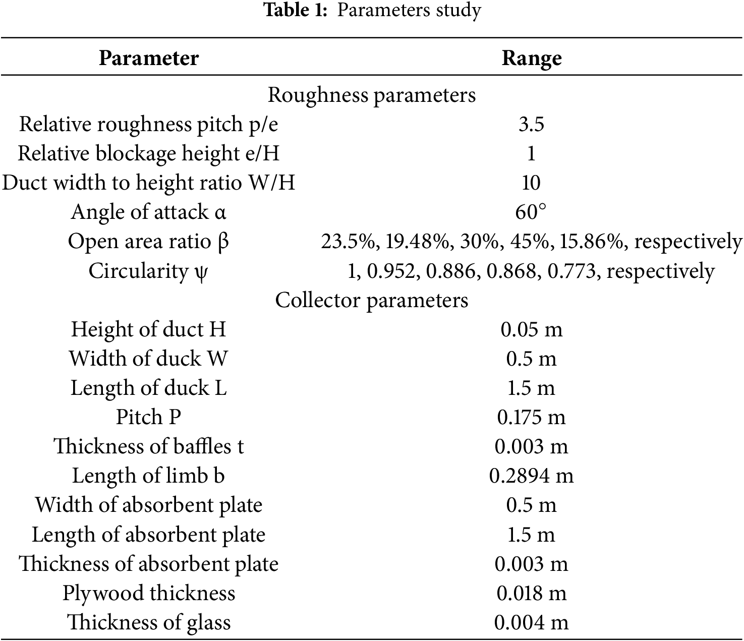
| p/e | Relative Roughness Pitch |
| e/H | Relative blockage height |
| W/H | duct width to height ratio |
| H | Height of Duct, (m) |
| W | Width of Duck, (m) |
| L | Length of Duck, (m) |
| P | Pitch, (m) |
| t | Thickness of baffles, (m) |
| b | Length of limb, (m) |
| K | Thermal convection coefficient, (W/K*m) |
| h | heat transfer conductivity coefficient |
| Cp | specific heat, (KJ/kg*K) |
| μ | Viscosity, (kg/m*s) |
| hydraulic diameter, (m) | |
| Re | Reynolds number |
| Nu | Nusselt number |
| f | fraction factor |
| m° | mass flow rate, (kg/s) |
| Q | heat transfer rate, (watt) |
| Air inlet temperature, (C°) | |
| Air outlet temperature, (C°) | |
| fluid temperature, (C°) | |
| plate temperature, (C°) | |
| Plate area, (m2) | |
| I | solar radiation incident, (W/m2) |
| THPP | thermohydraulic performance parameter |
| Greek Symbols | |
| α | angle of attack, (degree) |
| β | open area ratio, (percentage) |
| ψ | Circularity ratio |
| εg | Emissivity of Glass |
| εap | Emissivity of Paint/absorber plate |
| τα | Transmittance-absorptance of glass |
| ρ | Density, (kg/m3) |
| η | thermal efficiency for collector, percentage |
| Subscript | |
| i | outlet |
| o | inlet |
| f | fluid |
| p | plate |
| s | smooth |
| r | Non-smooth |
| Abbreviated | |
| SAH | Air solar heater |
Since ancient times, the heat of the sun has been harnessed for use in everyday life for heating and drying agricultural crops and product power. The sun has always been the primary source of energy on this planet [1], which can cover the annual global energy demand [2]. As the demand for energy increases with the development of civilization, it is necessary to rely on sustainable energy sources to achieve the energy and climate goals of reaching zero emissions globally by 2050 using low-emission energy. Burning fossil fuels represents 81% of energy supplies, but burning them has a negative impact on the environment, causing global warming. Therefore, it is necessary to transition to various renewable sources [3–5]. One way to exploit the sun’s energy is to use a solar air heater (SAH) [6–8], which converts the sun’s energy into useful thermal energy for heating and drying applications [9–11]. Air is ineffective in solar heaters due to its low thermal conductivity value [12]. Therefore, researchers in the literature have used multiple methods to increase the heat transfer between the absorbent plate and the air. Researchers have used various geometric shapes and designs for fins, obstacles, barriers, ribs, and artificial roughness to create a disturbance in the airflow by generating vortices. Breaking the viscous boundary sub-layer at the absorption plate’s surface increases the heat transfer rate [13–17]. One of the most common methods in the literature involves the use of V-shaped baffles in various designs to create artificial roughness. Different relative roughness widths, whether blocked, broken, or perforated, gave rise to trouble [18,19]. This was an experiment that used V-shaped perforated blockages to improve heat transfer. The holes were of different geometric shapes with different circularity (ψ) values, and the open area ratio (β), angle of attack (α), relative roughness pitch (p/e), relative blockage height (e/H), and duct width to height ratio (W/H) were all changed. The study determined that non-circular perforation holes performed best at 0.69, with p/e and e/H having an impact on the Nusselt number and fraction factor. The best thermal-hydraulic performance parameter THPP was 3 at
Furthermore, numerically experimented with various geometric shapes as artificial roughness found the best THPP at rectangular baffles was 2.28 [28], experimental study on the design of straight aluminum fins, 0.01 m long, with intervals between them 0.02 m, 0.06 m high, with duct height 0.08 m, arranged in a V-ship pattern at an angle of 45. Was tested in the Kingdom of Saudi Arabia at several inclination angles for the collector and was found that the best inclination angle in the summer was 20°, where it obtained the highest thermal performance, so the overall efficiency was 38.2% and the exergy efficiency was 26.4%, with an increase in temperature in the heater by 29.8°C. In an experimental study [29], baffles with different inclination angles were installed to improve the heat transfer coefficient through convection. The best value was the inclination angle β is 90, while the pressure drop was less in the isolated installation at inclination angles 45° and 135°. The optimum hydraulic thermal performance was achieved at an inclination angle of 45°. Furthermore, study [30] analyzed the numerical parametric of a new proposal for a rib with a circular perforated configuration. Initially, the analysis focused on determining the optimal distance between the ribs, followed by testing the impact of the distribution and number of holes in the ribs. It was the best performance when the pitch distance was 0.1 m with five circular perforated geometries; Nu improved by 8.5 and the fraction factor improved by 4.76, and THHP was 5.32 [31,32]. In the previous literature, the V-shape baffles were used as one of the most promising roads, but the use of perforated barriers was not addressed by researchers enough. This study proposed new perforated designs, specifically hexagon and triangle holes, as innovative solutions. Due to the unique geometric properties of this new design, the hexagonal holes’ obtuse angles will result in a smoother flow, while the triangular holes’ sharp angles will increase flow turbulence and the formation of vortices.
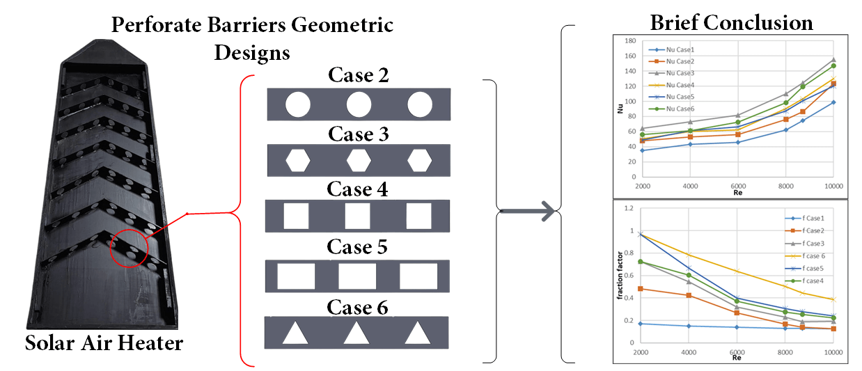
In this study, V-dawn perforated baffles with different geometric hole shapes (circle, hexagon, square, rectangle, and triangle) are analyzed, characterized by circularity values (
In this current study, the experimental work consists of a solar air heater (SAH) that uses materials available locally and is not expensive. The SAH consists of a rectangular duct that has dimensions of 1.5 m in length, 0.5 m in width, and 0.05 m in height from a wooden frame. Transparent glass covers the topside of the duct. The absorbent plate was made of aluminum because it has a higher thermal convection coefficient than galvanized iron and is more expensive than copper. The plate was 1.5 m by 0.5 m and 0.003 m thick. It was painted black to help it absorb heat and transfer heat better. Different geometrically designed perforated barriers were put on top of it to see how they affected thermal and hydraulic performance. A blower was used to force airflow. A digital manometer was used to measure the difference in pressure between the duct’s inlet and outlet, and a solar meter was used to measure the amount of solar radiation. K-type thermocouples were fixed inside the duct and connected to an Arduino to measure the temperatures. An anemometer was used to measure the speed of the flow in the duct. The experiment was done for six study cases, which contain different geometric perforated baffles inside the SAH duct. Fig. 1 shows the installation system, Fig. 2 shows the system structure, and Fig. 3 shows the dimensions of each case. Tables 1 and 2 summarize all the parameters used in this study.

Figure 1: Control system installation in this study
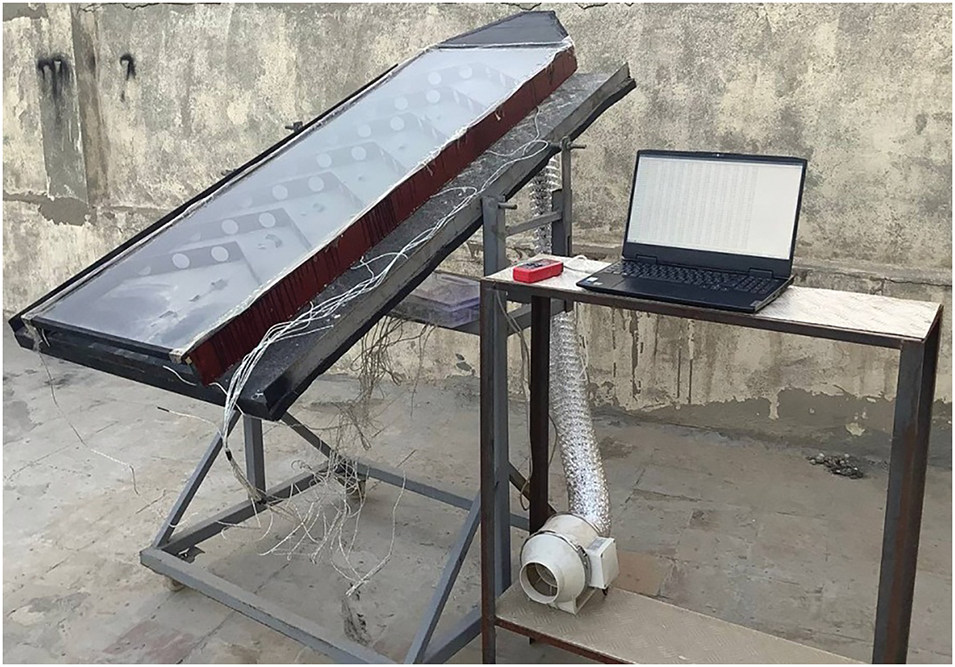
Figure 2: Physical construction of solar air heater system

Figure 3: Dimensions of the solar air heater system adopted in the current work

Case 1: Smooth absorbent plate used to compare the results.
Case 2: V-dawn perforated baffles on an absorbent plate with circular holes have an open area ratio β of 23.5% and a circularity of 1.
Case 3: V-dawn perforated baffles on an absorbent plate with hexagonal holes have an open area ratio β of 19.48% and a circularity of 0.952.
Case 4: V-dawn perforated baffles on an absorbent plate with square holes have an open area ratio β of 30%, and circularity is 0.886.
Case 5: V-dawn perforated baffles on an absorbent plate with rectangular holes have an open area ratio β of 45% and a circularity of 0.868.
Case 6: V-dawn perforated baffles on an absorbent plate with triangle holes have an open area ratio β of 15.86%, and circularity is 0.778.
Where Circularity ψ is representative of the closeness of the hole to the circular shape, it is the ratio of the equivalent perimeter pe of the equivalent circle having equal cross-section area for the non-circular hole area to the perimeter of the non-circular hole p. value of the circularity between 0 and 1. References [20–22] and the open area ratio β is the total area for holes in the baffle to the area of the block.
3 Experimental Measurement and Analysis
The outdoor experiment was performed in Baghdad. In this context, the experiment was conducted outdoors at 33°N and 44°E during November. The experiment was done for six study cases. All the essential parameters were measured and recorded: temperatures, mass flow rate, and solar radiation, at average values calculated from these parameters [21–25].
In a rectangular duct, air velocity V determines the mass flow rate m° [30].
Reynolds number for air flow through duct calculated as [21–25]:
where μ is the air viscosity, ρ is air density, and
The heat transfer rate Q from the heated plate to the flowing air was determined similarly to [30]:
where
The heat transfer coefficient
where
Nusselt number determined as [30]:
The heat conductivity coefficient for air is represented by K [21–25].
The Darcy-Wiesbach equation [21–25,30] determined the friction factor from the pressure drop due to the used baffles.
Except for the smooth case, the Blasius equation was used to determine the smooth fraction factor
Thermal efficiency for the collector was determined using Eq. (10) below:
where
The thermohydraulic performance parameter is a way to measure how heat transfer is improved and frictional losses are reduced in a collector that has been made to look rough. The determination of this parameter takes into account both the thermal efficiency and the pressure drop resulting from flow resistance, as demonstrated in [21–23,30].
where
The Nusselt number and friction factor characteristics of a rectangular duct equipped with V-shaped perforated blocks as a function of geometrical blockages and operating parameters of the system are being discussed below. We recorded the average temperature and solar radiation intensity for the entire duration of the test in November (Fig. 4). The average temperature during the day was about 15°C, and the solar radiation was about 765 W/m2.
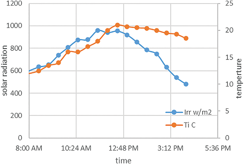
Figure 4: Average solar radiation and air inlet temperature during all experimental
As the Reynolds number increases, the temperature decreases due to the increased flow velocity, which does not allow the air to gain heat where the air does not have enough time to heat, as shown in Fig. 5. In case 3, the highest temperature was reached with an improvement of 66.5% at Re = 2000. Because of its hexagonal geometric shape holes, it has created more eddies than another case, so the temperature has a higher increase percentage, and with increasing flow, the temperature decreased to reach a maximum gain of 40% at Re = 10,000 compared to the smooth case (case 1). Case 6 was the second-best case, while the lowest recorded air outlet temperature was at case 2, due to the fact that the circular holes were unable to be a sufficient disturbance to generate eddy comparison with other cases. The convective heat transfer coefficient and the Nusselt number both go up as the Reynolds number goes up (Figs. 6, 7). This is because adding baffles makes the air more turbulent. The Nestled number improves by 1.7 and the heat transfer coefficient by 1.8, so Re = 2000 for case 3. As Re increases, Nu and f increase, so the improvement becomes 1.58 and 1.53, respectively. The improvement for the rest of the cases is in sequence from highest to lowest, thus case 6, case 4, case 5, and case 2. As for the fraction factor Fig. 8, it decreases with increasing Reynolds number, and its highest is in case 6, where due to the triangular shape, air turbulence increases significantly, followed by case 5, then case 4, case 3, and case 2 was decreases, respectively, in case 2 the fraction factor was the lest due have smooth corners unlike other shape. The use of barriers significantly increased both efficiency (FTTH, Figs. 9–10), and the best performance was for case 3. It had Re = 6000, so the efficiency was 98%, and FTTH was 1.35. Re = 8000 yielded 95% efficiency and 1.47 FTTH due to its hexagonal shape. This created turbulence in the air, leading to a significant increase in Nu and h values, while the fraction factor experienced a moderate rise, thereby reducing pressure losses. Next in performance is case 6, which has a triangular shape, as it reduced air turbulence well but caused an increase in the fraction factor. Case 2, with its circular hole, was less efficient than case 4 and case 5, but its FTTH management was superior due to its lower fraction factor.
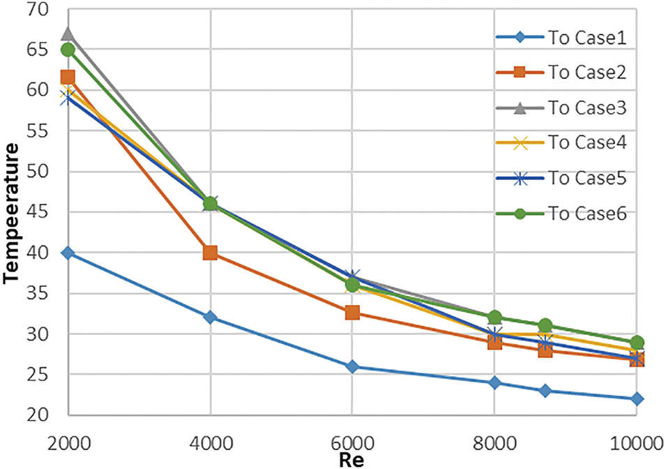
Figure 5: Average outlet temperature

Figure 6: Average Nusselt number

Figure 7: Heat transfer coefficient by convection with various in Reynolds number
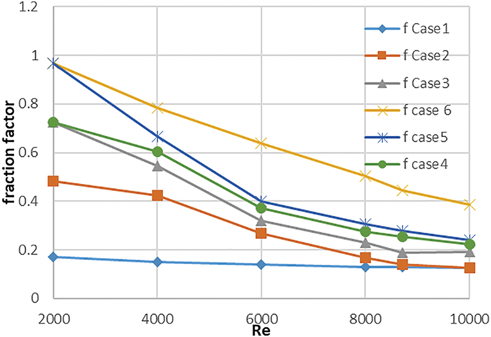
Figure 8: Fraction factor with various Reynolds number

Figure 9: Efficiency with Reynolds number

Figure 10: THPP with Reynolds number
In practical experiences, there is always a mistake between the measured value and the true value. This difference in uncertainty occurs due to the limited accuracy of the measurement devices. Table 3 shows the accuracy of the devices used in practical tests. Therefore, any parameter calculated based on these measurements includes a simple error percentage, but these proportions are few and do not affect the general results. So you can always trust the results.

To find out what the Nusselt number and friction factor are, we looked at the relative pitch ratio, relative blockage height, open area ratio, angle of attack, and circularity of the blockages, as well as the Reynolds number, which is a flow parameter. Therefore, we can state the functional relationship between the Nusselt number and friction factor using these parameters:
The relationship between the Nusselt number and the Reynolds number can be established by the fact that forced convection heat transfer always results in a power law of the form given below:
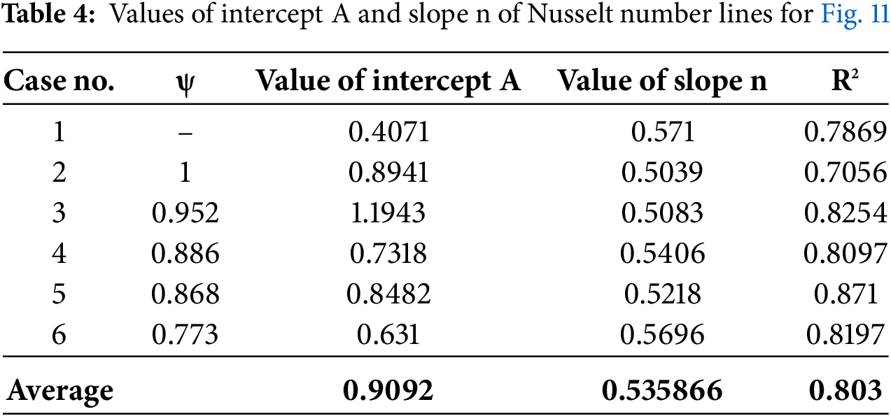
where A indicates the intercept and n slope of lines, the logarithmic form of the Nu equation can be written as in Eq. (15) and solved by Eq. (16).
By comparing the experimental values of the Nusselt number and the values predicted by the correlation for Nu (Figs. 11 and 12) it is found that the average values of the regression coefficient of this correlation are 0.803 (Table 4). R2 is the coefficient of determination that shows the extent to which the distribution fits the data. Its value is between 0 and 1. A value of R2 = 1 means that the distribution has a perfect fit, while a value of R2 = 0 means that the fit is fragile. The Root Mean Squared Error values for each case are 10.55, 14.769, 64, 13.957, 12.85, 9.18, and 14.77, respectively. The Average Absolute Deviation for each case is 8.19, 10.89, 11.51, 10.19, 7.6, and 12.5, respectively. And the error percentages for each case are 13.3%, 14.3%, 11.6%, 12.69%, 9.35%, and 14.47%, respectively. Therefore, we can conclude that this work’s developed correlation accurately predicts the Nusselt number values.

Figure 11: Nusselt number correlations

Figure 12: Comparison between experimental and predicted data of Nu
Moreover, by comparing the experimental values of fraction factor and the values predicted by the correlation for fraction factor (Figs. 13, 14, and Table 5), it is found that the Root Mean Squared Error for each case is 0, 0.065, 0.599, 0.065, 0.052, and 0.0577, respectively. The Average Absolute Deviation for each case is 0, 0.049, 0.042, 0.0458, 0.0335, and 0.051, respectively. And the error percentages for each case are 0%, 15.2%, 9.2%, 8.74%, 5%, and 7.97%, respectively. Thus, it can be concluded that the correlation developed in this work can predict the values of the fraction factor with reasonable accuracy.

Figure 13: Fraction factor Nusselt number correlations

Figure 14: Comparison between experimental and predicted data of fraction factor

Also, a comparison of the value of the Nusselt number between this study and the Tabish study [14] in Fig. 15 at ψ = 1 at the same Reynolds number was conducted. In this regard, in case of the Reynolds number values were low, there was a good match between both studies. Still, when the Reynolds number values were high, a difference occurred due to the difference in operating conditions between the two studies, where the Tabish study was indoor. Still, in this study, the experimental conditions were outdoors in November.
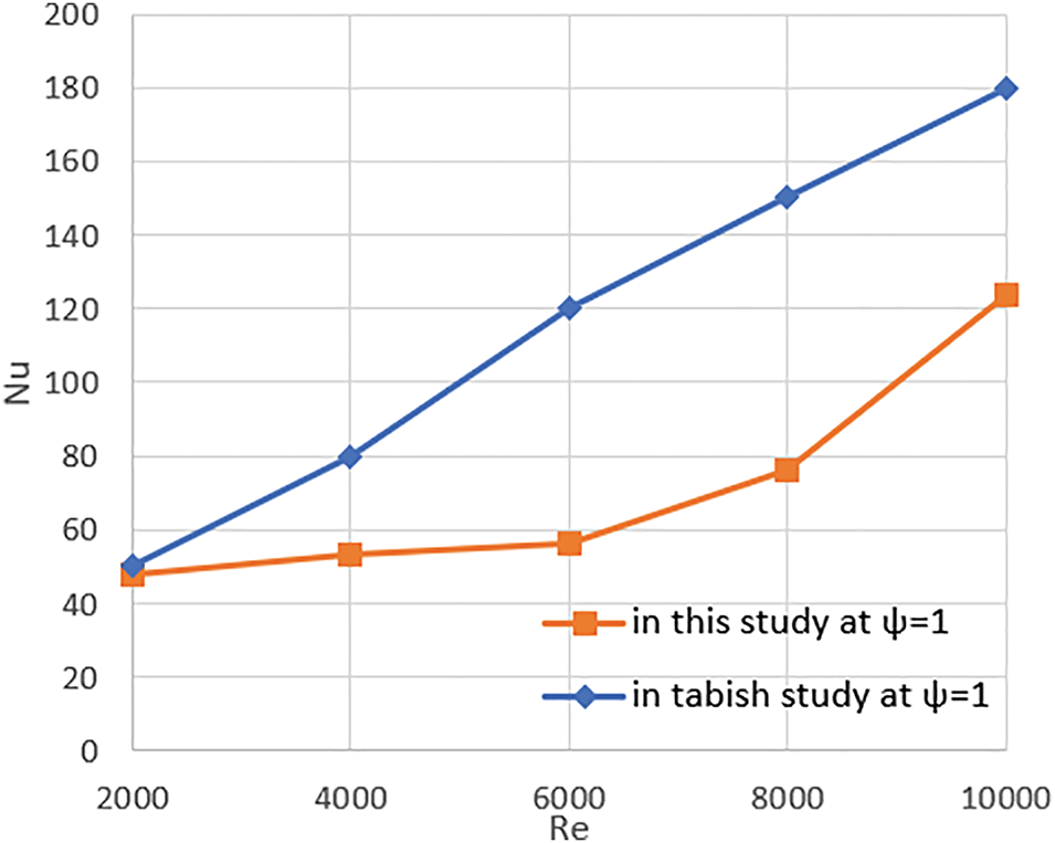
Figure 15: Comparison of the value of the Nusselt number between this study and tabish study
The research on enhancing the performance of solar air heaters identifies two main forms of artificial roughness, ribs and baffles, used to increase the efficiency of these heaters. Each category was further classified according to its shapes, sizes, orientations, and arrangements. Previous studies indicated the need for a comprehensive investigation into how baffle placement on the bottom plate affects airflow and efficiency in solar air heaters. In this work, the test apparatus consisted of a solar air heater (SAH) with perforated V-shaped blockages attached to one broad wall. The outdoor experiment was conducted in Baghdad at 33°N and 44°E during the month of November in the open air, where the tests started at 8 am and ended at 4 pm, and the average values were taken for each case. We also integrated the air temperature in the air duct of the solar air heater. We looked into what happened to the local convective heat transfer coefficients (Nu and ff) when we used perforated baffles with different geometrical shapes. Based on the following points, we can summarize the conclusions:
• The highest value of Nu was achieved at 155 in case 3, and for case 6, it was 129.94 at Re 10,000.
• The local convective heat transfer coefficient of the channel increases at the beginning of the air channel for each Re.
• The friction factor went down as Re went up in all the cases that were looked into. This was because there were more turbulent eddies at high mass flow rates, which made friction less important.
• The thermal efficiency estimation was performed by analyzing the heat losses due to convection with the outside air and long-wave radiation exchange with the sky. It was seen that the thermal efficiency is higher when Re is high. This suggests that adding baffles improves efficiency, which is especially clear in case 3.
• The best thermohydraulic performance parameter was 1.472 at Re 8000 for case 3, and the maximum thermal efficiency was 0.98% at Re 6000 for case 3.
• The best increase in temperature was achieved using the hexagonal perforated, followed by the triangular and then the circular; the maximum values were 67°C, 65°C, and 61.6°C, respectively.
According to the above, case 3 with the hexagonal hole performed the best due to its distinctive design, which increased air turbulence and raised the Nu value without increasing the Fracture Factor significantly. This was followed by case 4 with a square hole, which had an FTTH of 1.14, indicating a suitable increase in both Nu and Fair Factor. Followed by case 2 with a circular hole, as he did not generate a major disorder because it does not contain sharp corners, but the Fraction Factor was few, while the worst design was case 4 with a rectangular hole and then case 6 with a triangular hole, as they had a huge Fraction Factor, which FTTH was 1.06 and 1.01, respectively. In future work, we recommend that these models be tested in various weather conditions and with different values of open area ratios for the perforated hexagonal and triangle holes.
Acknowledgement: We would like to express our sincere gratitude to the University of Technology that has supported this work.
Funding Statement: The authors received no specific funding for this study.
Author Contributions: Study conception and design: Sajjad Tariq A. Shafi, Mohammed K. Al-Saad, and Ameer Abed Jaddoa; data collection: Sajjad Tariq A. Shafi, Mohammed K. Al-Saad, and Ameer Abed Jaddoa; analysis and interpretation of results: Sajjad Tariq A. Shafi, Mohammed K. Al-Saad, and Ameer Abed Jaddoa; draft manuscript preparation: Sajjad Tariq A. Shafi, Mohammed K. Al-Saad, and Ameer Abed Jaddoa. All authors reviewed the results and approved the final version of the manuscript.
Availability of Data and Materials: All the data required to establish this work is available in the manuscript.
Ethics Approval: This study does not include the participation of humans, animals, or any unethical actions.
Conflicts of Interest: The authors declare no conflicts of interest to report regarding the present study.
References
1. Abulkhair H, Alsaiari AO, Ahmed I, Almatrafi E, Madhukeshwara N, Sreenivasa BR. Heat transfer and air flow friction in solar air heaters: a comprehensive computational and experimental investigation with wire-roughened absorber plate. Case Stud Therm Eng. 2023;48(3):103148. doi:10.1016/j.csite.2023.103148. [Google Scholar] [CrossRef]
2. AbdelFatah RT, Fahim IS, Kasem MM. Investigative review of design techniques of parabolic trough solar collectors. Front Heat Mass Transf. 2024;22(1):317–39. doi:10.32604/fhmt.2023.044706. [Google Scholar] [CrossRef]
3. IEA. World energy investment 2024; 2024. [Online]. [cited 2025 Mar 11]. Available from: www.iea.org. [Google Scholar]
4. Abed Jaddoa A. An empirical study of the electric solar refrigerator based on Iraqi’s environment. In: AIP Conference Proceedings, Iraq; 2024 July 19–20; Baghdad, Iraq; 2024. Vol. 3002. doi:10.1063/5.0205774. [Google Scholar] [CrossRef]
5. I. Energy Agency. World energy outlook 2024; 2024. [Internet]. [cited 2025 Mar 11]. Available from: www.iea.org/terms. [Google Scholar]
6. Hassan Q, Viktor P, Al-Musawi TJ, Mahmood Ali B, Algburi S, Alzoubi HM, et al. The renewable energy role in the global energy transformations. Renew Energy Focus. 2024;48(12):100545. doi:10.1016/j.ref.2024.100545. [Google Scholar] [CrossRef]
7. Jain SK, Misra R, Kumar A, Das Agrawal G. Thermal performance investigation of a solar air heater having discrete V-shaped perforated baffles. Int J Ambient Energy. 2022;43(1):243–51. doi:10.1080/01430750.2019.1636874. [Google Scholar] [CrossRef]
8. Ameer AJ. N assessing the effectiveness of hybrid solar collectors scheme iniraq’s environment. Eurasian Phys Tech J. 2023;20(2 (44)):57–64. doi:10.31489/2023No2/57-64. [Google Scholar] [CrossRef]
9. Atia DB, AL-Saadi MK, Abed Jaddoa A. Modeling of a domestic hybrid electric/solar water heating system. In: AIP Conference Proceedings; 2024 July 19–20; Baghdad; Iraq; 2024. Vol. 3002. doi:10.1063/5.0206383. [Google Scholar] [CrossRef]
10. Abedalh AS, Mohammed SH. Numerical investigation thermal performance of solar air heater using different angle V-grooved of corrugated absorber plate. Front Heat Mass Transf. 2023;21(1):227–43. doi:10.32604/fhmt.2023.041777. [Google Scholar] [CrossRef]
11. Mahdİ M, Jaddoa A. An experimental optimization study of a photovoltaic solar pumping system used for solar domestic hot water system under Iraqi climate. J Therm Eng. 2021;7(2):162–73. doi:10.18186/thermal.871296. [Google Scholar] [CrossRef]
12. Mahdi MM, Abed Gaddoa A. Outdoor testing of a zig-zag solar air heater with and without artificial roughness on absorber plate. Jcoeng. 2019;25(4):1–17. doi:10.31026/j.eng.2019.11.01. [Google Scholar] [CrossRef]
13. Bahuguna R, Chamoli S, Barthwal Y, Rana S, Gupta A, Singh Bisht V. Economic analysis of artificially roughened solar air heater with v-shaped ribs. Acta Innov. 2022(44):18–33. doi:10.62441/actainnovations.v44i.289. [Google Scholar]
14. Khudheyer AF, abdul-Wahab AM. Solar thermal collectors with and without fins have been thoroughly evaluated for their performance analysis. Int J Adv Eng Manag. 2021;3:1463. [Google Scholar]
15. Goel V, Hans VS, Singh S, Kumar R, Pathak SK, Singla M, et al. A comprehensive study on the progressive development and applications of solar air heaters. Sol Energy. 2021;229(2):112–47. doi:10.1016/j.solener.2021.07.040. [Google Scholar] [CrossRef]
16. Sabet GS, Sari A, Fakhari A, Afsarimanesh N, Organ D, Hoseini SM. An experimental and numerical thermal flow analysis in a solar air collector with different delta wing height ratios. Front Heat Mass Transf. 2024;22(2):491–509. doi:10.32604/fhmt.2024.048290. [Google Scholar] [CrossRef]
17. Prasad RS, Nayak RK, Nayak UK, Gupta AK. Performance analysis of longitudinal fin jet plate solar air heater under cross flow condition. Front Heat Mass Transf. 2022;19:1–22. doi:10.5098/hmt.19.22. [Google Scholar] [CrossRef]
18. Jain SK, Das Agrawal G, Misra R. A detailed review on various V-shaped ribs roughened solar air heater. Heat Mass Transf. 2019;55(12):3369–412. doi:10.1007/s00231-019-02656-4. [Google Scholar] [CrossRef]
19. Mahdi MM, Jaddoa AA, Al Ezzi A. Impact of pumping head on a solar pumping system with an optimal PV array configuration: solar water heater application. J Eng Sci Technol. 2022;17(3):2035–48. [Google Scholar]
20. Alam T, Saini RP, Saini JS. Heat transfer enhancement due to V-shaped perforated blocks in a solar air heater duct. Appl Mech Mater. 2014;619:125–9. doi:10.4028/www.scientific.net/amm.619.125. [Google Scholar] [CrossRef]
21. Alam T, Saini RP, Saini JS. Experimental investigation of thermohydraulic performance of a rectangular solar air heater duct equipped with V-shaped perforated blocks. Adv Mech Eng. 2014;6:948313. doi:10.1155/2014/948313. [Google Scholar] [CrossRef]
22. Alam T, Saini RP, Saini JS. Effect of circularity of perforation holes in V-shaped blockages on heat transfer and friction characteristics of rectangular solar air heater duct. Energy Convers Manag. 2014;86:952–63. doi:10.1016/j.enconman.2014.06.050. [Google Scholar] [CrossRef]
23. Lertnuwat B. Effect of the number and placement of punched holes in rectangular winglet vortex generators on solar air heater performance. Energy Convers Manag X. 2024;24:100714. doi:10.1016/j.ecmx.2024.100714. [Google Scholar] [CrossRef]
24. Eiamsa-ard S, Phila A, Wongcharee K, Pimsarn M, Maruyama N, Hirota M. Thermal evaluation of flow channels with perforated-baffles. Energy Rep. 2023;9:525–32. doi:10.1016/j.egyr.2023.01.064. [Google Scholar] [CrossRef]
25. Menni Y, Chamkha AJ, Zidani C, Benyoucef B. Analysis of thermo-hydraulic performance of a solar air heater tube with modern obstacles. Arch Thermodyn. 2020;41(3):33–56. doi:10.24425/ather.2020.134571. [Google Scholar] [CrossRef]
26. Raturi P, Deolal H, Kimothi S. Numerical analysis of the return flow solar air heater (RF-SAH) with assimilation of V-type artificial roughness. Energy Built Environ. 2024;5(2):185–93. doi:10.1016/j.enbenv.2022.09.002. [Google Scholar] [CrossRef]
27. Agarwa A, Ilunga M, Tempa K, Humagai BK. CFD analysis of solar air heater using V-shaped artificial roughness to attain heat transfer enhancement. Int J Energy Prod Manag. 2024;9(3):171–80. doi:10.18280/ijepm.090306. [Google Scholar] [CrossRef]
28. Salarpour N, Azadani LN. Optimization and evaluation of thermo-hydraulic performance of solar air heaters equipped with different roughness geometries. Case Stud Therm Eng. 2024;61(14):105037. doi:10.1016/j.csite.2024.105037. [Google Scholar] [CrossRef]
29. Alrashidi A, Altohamy AA, Abdelrahman MA, Elsemary IMM. Energy and exergy experimental analysis for innovative finned plate solar air heater. Case Stud Therm Eng. 2024;59:104570. doi:10.1016/j.csite.2024.104570. [Google Scholar] [CrossRef]
30. Aouissi Z, Chabane F, Teguia MS, Bensahal D, Moummi N, Brima A. Determination of the heat transfer coefficient by convection, according to shape of the baffles (solar air collector). J Ren Energies. 2022;25(1):43–54. doi:10.54966/jreen.v25i1.1070. [Google Scholar] [CrossRef]
31. Salhi JE, Alami Merrouni A, Amrani AI, Chaabelasri E, Lamrani Alaoui A, Talbi S, et al. Three-dimensional analysis of a novel solar air heater conception, for an improved heat transfer and energy conversion. Energy Convers Manag X. 2023;19(51):100386. doi:10.1016/j.ecmx.2023.100386. [Google Scholar] [CrossRef]
32. Salhi JE, Zarrouk T, Taoukil D. Parametric analysis for optimizing performance of solar air heating systems with innovative rib configurations. Int Commun Heat Mass Transf. 2024;158(8):107869. doi:10.1016/j.icheatmasstransfer.2024.107869. [Google Scholar] [CrossRef]
33. Phu NM, Thao PB, Van Hap N. Effective efficiency assessment of a solar air heater having baffles spaced with different successive ratios. Case Stud Therm Eng. 2021;28(6):101486. doi:10.1016/j.csite.2021.101486. [Google Scholar] [CrossRef]
34. Bergman TL, Lavine AS, Incroper FP, De Witt DP. Fundamentals of heat and mass transfer. 17th ed. USA: John Wiley & Sons, Inc.; 2011. [Google Scholar]
Cite This Article
 Copyright © 2025 The Author(s). Published by Tech Science Press.
This work is licensed under a Creative Commons Attribution 4.0 International License , which permits unrestricted use, distribution, and reproduction in any medium, provided the original work is properly cited.
 Downloads
 Citation Tools