
 Submit a Paper
 Propose a Special lssue
 Open Access
ARTICLE

Innovative Dual Two-Phase Cooling System for Thermal Management of Electric Vehicle Batteries Using Dielectric Fluids and Pulsating Heat Pipes
1 Department of Engineering for Industrial Systems and Technologies, University of Parma, Parco Area delle Scienze 181/A, Parma, 43124, Italy
2 SITEIA.PARMA Interdepartmental Centre, University of Parma, Parco Area delle Scienze, Parma, 43124, Italy
* Corresponding Author: Fabio Bozzoli. Email:
(This article belongs to the Special Issue: Heat and Mass Transfer Applications in Engineering and Biomedical Systems: New Developments)
Frontiers in Heat and Mass Transfer 2025, 23(5), 1351-1364. https://doi.org/10.32604/fhmt.2025.064154
Received 06 February 2025; Accepted 25 July 2025; Issue published 31 October 2025
 View Full Text
 Download PDF
Abstract
This study investigates the feasibility of a novel dual two-phase cooling system for thermal management in lithium-ion batteries used in electric vehicles (EVs). The proposed system aims to combine low-boiling dielectric fluid immersion cooling and pulsating heat pipes (PHPs), in order to leverage the advantages of both technologies for efficient heat dissipation in a completely passive configuration. Experimental evaluations conducted under different discharge conditions demonstrate that the system effectively maintains battery temperatures within the optimal range of 20–40°C, with enhanced temperature uniformity and stability. While the PHP exhibited minimal impact at low power, its role became critical under higher discharge rates, ensuring efficient vapor condensation and pressure stability. The results highlight the potential of this passive cooling system to improve battery performance and safety, supporting its application in EV battery thermal management. Future work aims to optimize design parameters and evaluate real battery modules under ultra-fast charging scenarios.Keywords
In the last decade, due to increasingly concerning issues of air pollution and global warming, the concept of ecological transition has emerged to limit the use of fossil fuels and reduce pollutant emissions, especially CO2. Within this framework, electrification plays a fundamental role as an alternative to fossil fuels, since if electricity is produced using clean technologies such as solar and wind energy, it could significantly reduce pollutant emissions. The trend towards electrification is evident in the automotive sector, where the electric vehicle market is expanding. This is partly thanks to the development of higher-performance batteries, which have addressed critical issues such as range and power limitations for electric vehicles. Additionally, with the introduction of fast charging, battery charging times have been shortened. There are various types of batteries available on the market that have been used in the past and are still used today in automotive applications. They differ primarily in the materials used and their structure, which define their main characteristics. Without a doubt, the greatest focus in comparisons is on specific energy and specific power, as these ensure greater efficiency and a lower battery pack weight for the same required performance [1]. Lithium-Ion batteries are considered the most promising technology for the future of mobility electrification, thanks to their advantages over other types of batteries. There are numerous cell configurations available on the market today, with various shapes and materials. These batteries are characterized by a high energy storage capacity with an excellent energy density-to-weight ratio, as lithium has both a high electrochemical potential and a low equivalent mass. They offer high efficiency and a long lifespan, and their improvement potential is regarded as very high [2–5]. Technological advancements lead to greater thermal output from battery modules, resulting in higher temperatures. Operating temperature is a crucial factor because it directly impacts battery performance and lifespan. At high temperatures, battery cells experience accelerated aging, reducing their available capacity, and similar issues can occur at low temperatures. The optimal operating range for batteries is between 20°C and 40°C, making it essential to introduce systems capable of regulating temperature [6]. These systems, known as Battery Thermal Management Systems (BTMS), effectively dissipate the heat generated and help prevent performance degradation in batteries. Research papers discuss diverse methods for cooling batteries, with the simplest techniques frequently relying on air-based cooling systems, frequently combined with heat sinks or radiating fins to enhance heat dissipation [7]. However, these air-based systems are generally insufficient for high-power applications, like electric vehicles, where thermal management demands are significantly higher. Cooling methods based on liquid systems, especially those employing single-phase or two-phase refrigerants [8–11], have shown enhanced effectiveness in electric vehicles owing to their greater ability to absorb and transfer heat and better heat transfer properties. As a result, direct cooling BTMS have gained attention as an innovative approach for controlling thermal conditions in Lithium-Ion battery cells used in electric vehicles [12–14]. New advancements in thermal management technologies have also led to the exploration of more innovative systems. Phase Change Materials (PCMs) [15] have emerged as an interesting solution, as they can absorb and release heat during phase transitions, helping to stabilize temperature fluctuations within the battery pack. Additionally, heat pipe-based cooling solutions [16–19] are being investigated for their ability to efficiently transfer heat away from critical components by using the principles of evaporative cooling, offering enhanced thermal control in demanding environments. These emerging methods are being studied as part of ongoing efforts to improve the efficiency and reliability of thermal management in lithium-ion battery systems, particularly in the high-performance sector of electric vehicles. In recent studies, a promising approach consists of implementing multiple cooling technologies within the same system to leverage the advantages of each individual technology. In this context, the present research introduces a novel solution for managing battery temperature by combining dual-phase liquid cooling with Pulsating Heat Pipes (PHPs). PHPs are a type of dual-phase passive system driven by capillary action, consisting of a narrow tube or channel that alternates between the evaporation and condensation sections [20,21]. These systems rely on the capillary action of the working fluid to transport heat, which results in a highly efficient and self-regulating heat transfer process. Unlike other heat transport technologies, PHPs stand out due to their simplicity in design and cost-effectiveness, making them an attractive solution for a variety of thermal management applications [20,21]. Their passive nature, combined with their efficiency, positions them as an ideal choice for integrating into advanced battery thermal management systems. The proposed thermal management system operates entirely passively, as opposed to most conventional cooling technologies, removing the requirement for electrical energy usage and enabling the adoption of a compact power source. This approach makes the system both energy-efficient and cost-effective. The battery thermal management system in question provides an innovative solution, combining excellent thermal performance with passive functionality, making it a highly promising option for modern applications. In this system, the cells are submerged in a dielectric fluid with a low boiling point inside a transparent Plexiglass box, which serves to enhance visibility while ensuring safe operation. The use of pulsating heat pipes within the system plays a key role in managing heat spikes, facilitating the vapor recondensation process and helping to maintain consistent and safe temperature levels for the battery cells. To evaluate the effectiveness of the proposed system, a dedicated experimental setup was designed, with tests conducted using 1C and 2C discharging rates for fully discharging cycles under constant current conditions, replicating real-world electric vehicle battery applications. This is the first step of a broader work aimed at further validating the system’s effectiveness and determining its long-term viability for electric vehicle applications and represents a feasibility study of the proposed setup. For this experimental demonstration, a device designed to replicate a perfect PHP, engineered to operate at peak efficiency, was adopted—specifically, a PHP crafted to achieve its maximum theoretical performance. The experimental results were highly promising, demonstrating that the thermal management system maintains battery in the ideal range of temperatures even during demanding settings. This suggests that the proposed BTMS can effectively support the heat dissipation needs of EVs batteries during extended or intensive use.
The proposed BTMS was developed for practical use with a battery pack composed of 6 SKI E566 cells in series, each featuring 3.5 V of nominal voltage and 55.6 Ah of capacity. These kinds of battery cells, along with similar setups, are widely utilized in electric vehicles [22]. To replicate the thermal characteristics of the 6 cells, 4 aluminum plates were used. The plates were designed to match the battery pack thermal capacity, and they were heated thanks to adhesive flexible heaters with polyimide insulation (OMEGA KHA-305/10-P, Omega Engineering, Norwalk, CT, USA). The heaters were connected to DC programmable power sources (AIM-TTI INSTRUMENTS EX354RT, Aim and Thurlby Thandar Instruments, Huntingdon, UK), charatcerized by a current accuracy of 0.5% of the reading within the range of 0–5 A and a resolution of 1 mA, and a voltage accuracy of 0.3% of the reading within the range of 0–70 V and a resolution of 10 mV. The aluminum plates were custom sized to align with the actual size of the battery pack, enabling the prototype to carefully replicate the real-world implementation. While they cannot reproduce the localized performance of individual cells, they provide a truthful representation of the battery pack’s overall thermal performance. They were convened and placed inside a Plexiglas enclosure of 420 × 120 × 250 mm, with the plates positioned in the middle. This setup employs a BTMS that integrates two different two-phase chilling techniques: immersion in a fluid with a low boiling point and a PHP (refer to Fig. 1).
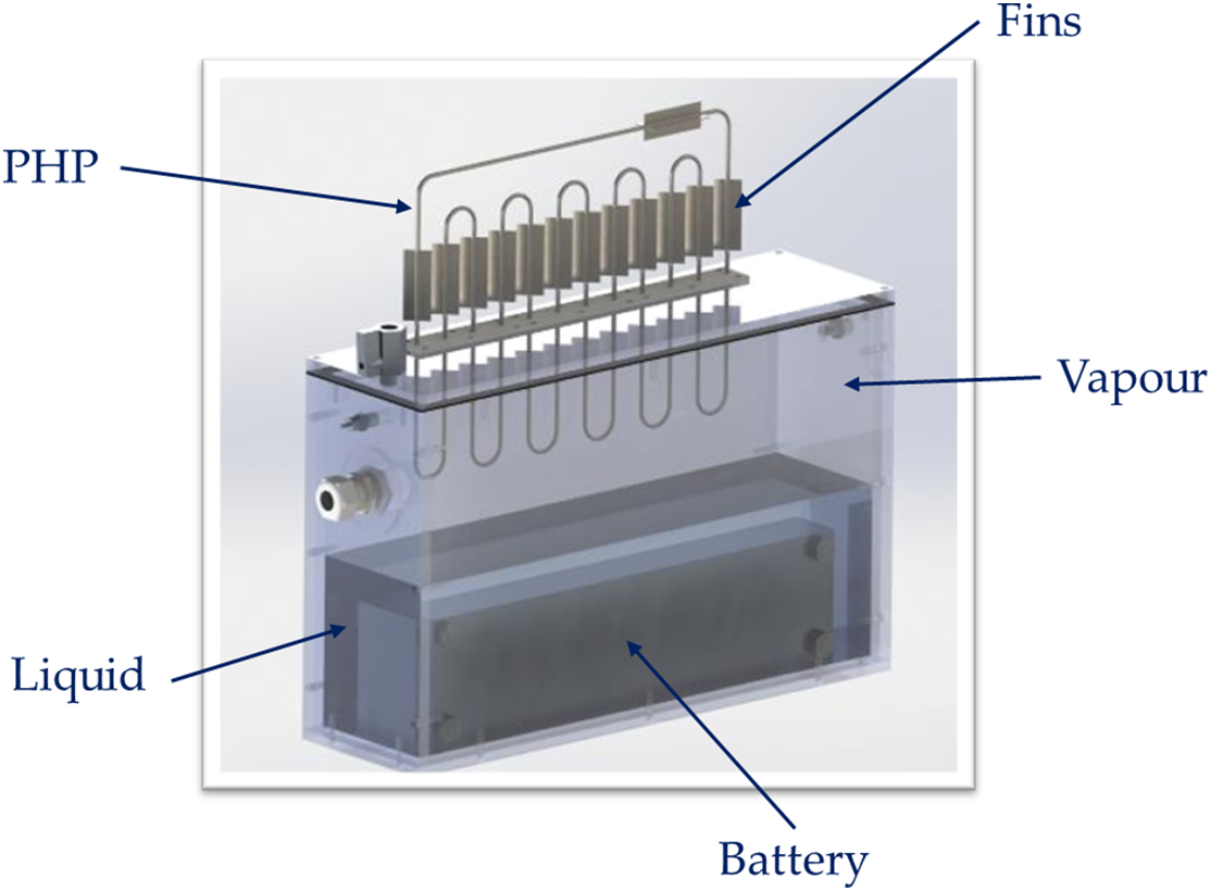
Figure 1: Sketch of the dual two-phase cooling system
The fluid for the immersion cooling, Opteon SF-33, was chosen primarily for its low boiling point, with a boiling temperature of 33.4°C at atmospheric pressure, ensuring that the phase change occurs within the optimal operating range for lithium-ion batteries (20–40°C). This allows for the use of latent heat, which is released during the fluid’s evaporation, in contrast to sensible heat, enabling greater heat dissipation. Other key characteristics for the application include high resistivity and low dielectric constant, which help prevent issues arising from direct contact with the battery or in the present case with the thermal resistances placed on the aluminum plates. Its non-flammability also enhances safety in the event of a thermal runaway and reduces the risk of fire. Our system’s dielectric fluid maintains an equilibrium state between its liquid and vapor forms. As previously described, the PHP is constituted of three distinct regions: the evaporator section, the condenser section, and the adiabatic section. The device absorbs heat from the system at the evaporator, and through the movement of liquid and vapor bubbles within the tube, it transports and dissipates the heat externally through the condenser section. The evaporator section of the PHP (see Fig. 2) is located inside the vapor phase within the Plexiglas enclosure, with the condensing section located outside, employing natural convection from the surrounding air for heat release. In the first phase of the project, to test the feasibility of incorporating a PHP into the vapor phase of the fluid, we decided to employ a heat exchanger that operates as an Ideal Pulsating Heat Pipe (IPHP). When assessing the thermal efficiency of PHPs, one frequently used metric is the equivalent thermal resistance (Req) [20,21]. The equivalent thermal resistance is determined applying the subsequent equation:
where Teva (°C) represents the temperature of the evaporator, Tcond (°C) denotes the temperature of the condenser, and Q (W) is the heat load provided at the evaporator section. An IPHP is distinguished by an almost null Req, representing perfect thermal functioning where the heat received at the evaporative section is efficiently transferred to the condenser lacking opposition, ensuing in no thermal gradient among the two sections. For this IPHP, a stainless-steel tube with inner and outer radiuses of 0.88 and 1.59 mm, respectively, was twisted into 11 coils, mimicking the geometry of an actual PHP. Stainless-steel tubes were selected due to their availability and affordability, two important qualities for factory-based devices. To meet the ideal requirement of Req ≈ 0, a high-speed water flow was introduced through the tube. This ensured a constant temperature throughout the entire IPHP, effectively replicating the ideal Req ≈ 0 scenario. To maintain the necessary water flow rate at the designated temperature, a chiller (Haake Kryo thermal 140, Vreden, Germany) was used in recirculation mode. To monitor temperature, several type T thermocouples (Copper-Constantan) were placed on the aluminum plates to assess the battery’s temperature profile, as well as in the liquid and vapor zones to track the behavior of Opteon SF33 in both phases. Additional sensors were installed on the branches of the evaporator and condenser within the PHP structure to control the temperature and to evaluate whether the water flow rate and available heat exchange surface were sufficient. The positions of the thermocouples and thermal resistances are summarized in Fig. 3. Thermocouples were connected to an ice point reference to ensure an uncertainty of ±0.1°C. Fluid pressure monitoring has been accomplished by adopting a pressure sensor (Kulite® XTL-190S-500 PSI SG, Leonia, NJ, USA) that was embedded into the box. Transducer signals for pressure were collected using AGILENT 34970A data acquisition device, which offers a resolution of 0.076 mV in the 0–10 V range, with an uncertainty of ±0.25 mV.
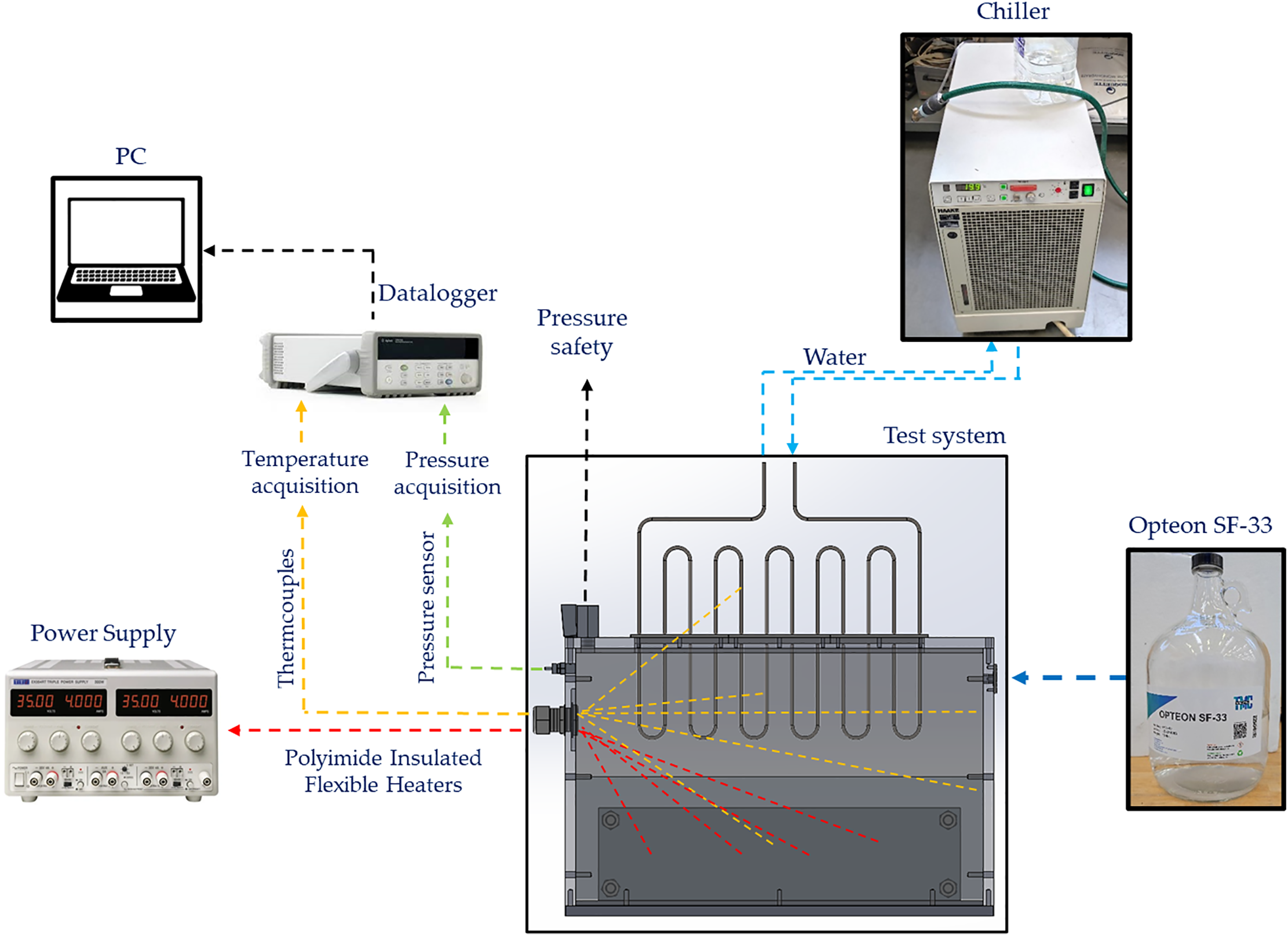
Figure 2: Experimental setup scheme

Figure 3: Position of (a) thermocouples and (b) thermal resistances
The tests involve monitoring the temperatures of the setup’s components and the pressure across three distinct cooling systems: natural convection, direct immersion cooling in dielectric fluid, and direct immersion cooling in dielectric fluid combined with an IPHP. For each configuration, the battery undergoes discharge at two different C-rates, specifically 1C and 2C. Consequently, a total of six tests are conducted, with each test repeated twice to ensure the reliability and consistency of the results. Throughout the experiments, the ambient temperature is carefully maintained at approximately 20°C to minimize external influences on the findings.
To evaluate the performance of the suggested cooling mechanism under practical battery working scenarios, experimental trials were conducted by applying a power load to aluminum blocks. This applied power simulated thermal energy produced during two different battery discharge cycles. These discharge profiles represented complete depletion processes carried out at steady operating currents, corresponding to different discharge rates, namely 1C and 2C. To estimate the heat output from a single battery cell, the Bernardi equation [23,24] was utilized:
here, I represents the discharge current, V denotes the cell voltage, T is the temperature at the battery surface (measured in K), UOC refers to the open-circuit voltage, and
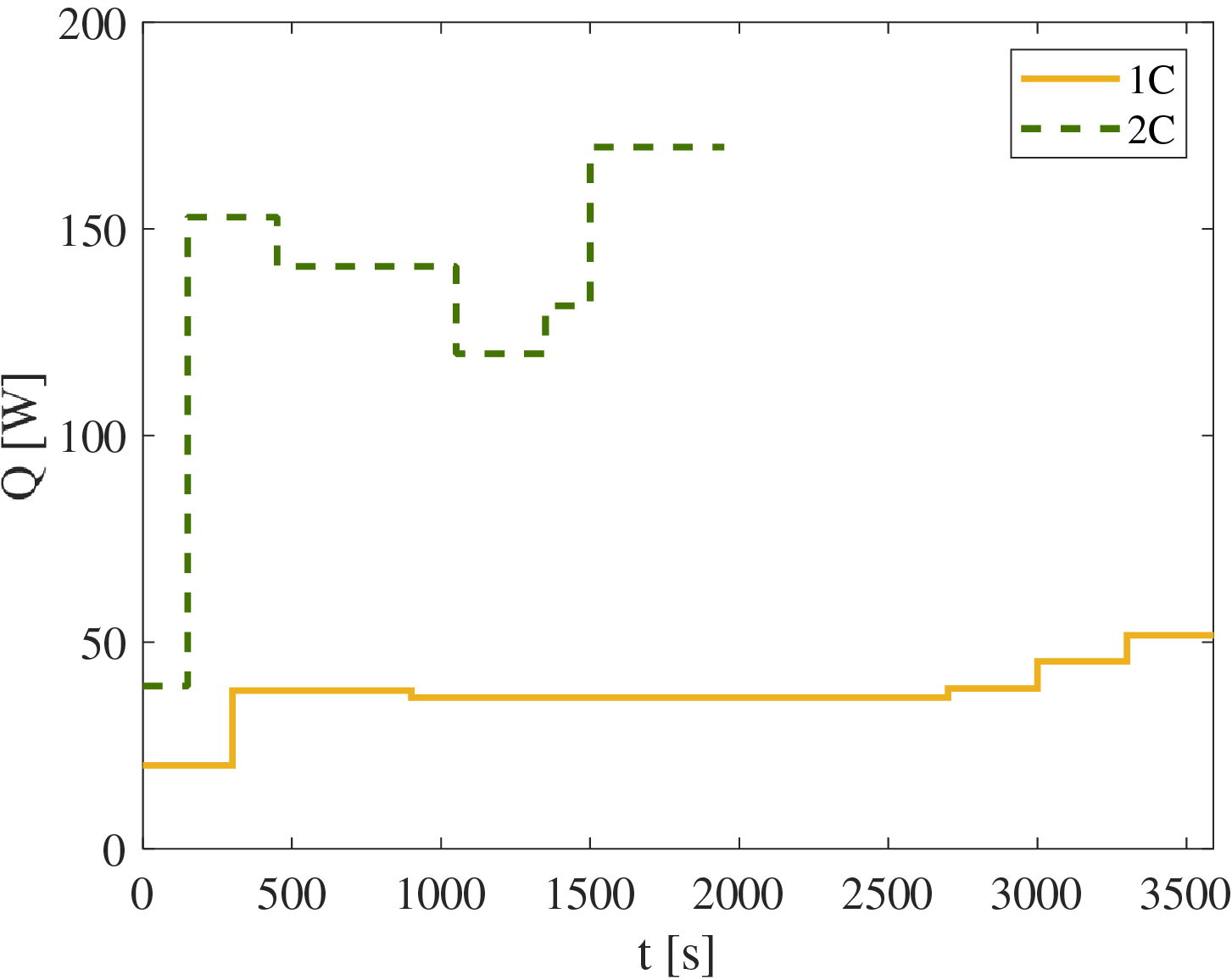
Figure 4: Discharging curves at different C-rates
The main goal of the BTMS is to keep the maximum temperature under 40°C to avoid malfunction or the risk of thermal runaway issues. Therefore, one of the most important parameters for evaluating the cooling system’s efficiency is certainly the maximum temperature reached by the battery during testing. In Fig. 5, the maximum temperatures recorded on the battery are shown for the BTMS here proposed together with the other two configurations considered for comparison, i.e., battery cooled by only immersion cooling with Opteon SF33 and battery cooled by natural convection with air. In all these scenarios, the ambient temperature was maintained at approximately 20°C. Similarly, the water circulating through the pipe in the BTMS was kept at the same temperature of 20°C to ensure consistency and comparability with the natural convection setup. This choice was crucial for accurately evaluating the thermal performance of the different configurations under similar environmental conditions. It can be observed that the configuration with the highest values is natural convection. The battery reaches a maximum temperature of 48°C at the end of the test. This value is above the recommended operating range for electric batteries, which should remain between 20 and 40°C. In contrast, the introduction of the low-boiling liquid helps reduce the temperature increase, keeping it below 33°C. However, there is essentially no temperature difference between the configuration with the IPHP and the one without. Starting from the same initial temperature, both setups reach the same maximum temperature of 32°C by the end of the test. The observed efficient management of total heat dissipation is attributed to the dielectric liquid’s high thermal capacity, combined with natural convection through the container walls to the surrounding environment. Notably, the temperature of Opteon SF33 remains below its boiling point of approximately 33°C, preventing significant vapor development. This reveals that the IPHP acts a marginal part in heat exchange during the 1C tests, without influencing the fluid’s temperature behavior or the thermal profile of the battery.
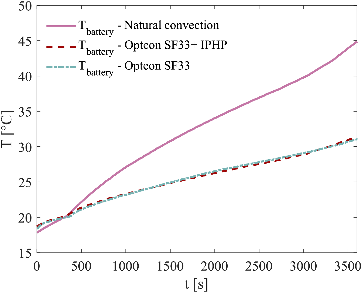
Figure 5: Maximum temperature measured at the battery for the 3 considered configurations for 1C discharging
As shown in Fig. 6, the internal pressure within the enclosure remains stable under both conditions involving the presence of Opteon SF33, primarily because the boiling temperature is not reached. The pressure readings for the IPHP configuration are slightly lower than those for the setup containing only the dielectric liquid; however, the difference—around 0.01 bar—is minimal and can be considered insignificant for analysis purposes. These findings underscore the effectiveness of the dielectric liquid and the stability of the system under the tested operating conditions.
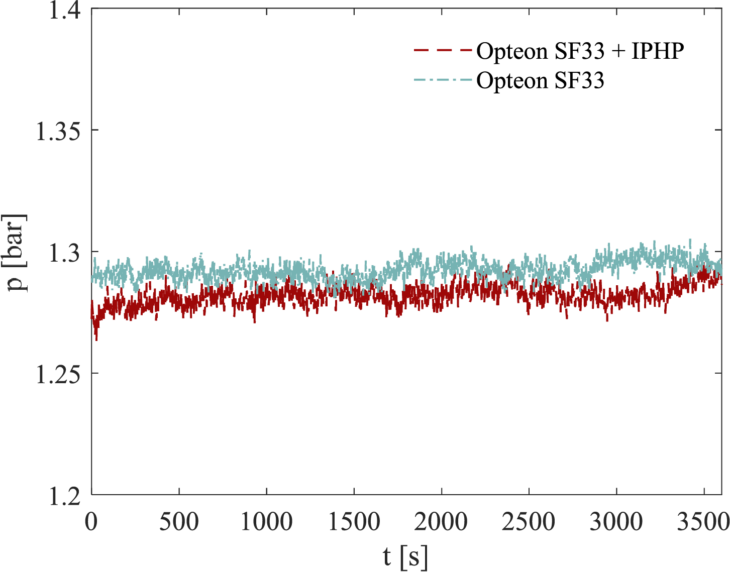
Figure 6: Pressure distribution vs time inside the box for 1C discharging
Another crucial parameter in evaluating a BTMS is the temperature difference (ΔT) measured within the battery. The recommended maximum temperature variation is approximately 5°C, as exceeding this threshold can lead to operational inefficiencies or potential damage. During testing, natural convection failed to meet this criterion, with a ΔT of 11°C observed during the later stages of the experiment. In contrast, when the battery was fully immersed in dielectric fluid, the results improved substantially, as illustrated in Fig. 7. The temperature variation remained well below the recommended limit. For both configurations tested, a similar pattern emerged: with a ΔT of approximately 2°C, the fluid’s complete contact with all battery surfaces facilitated uniform heat distribution. Moreover, no significant difference in performance was observed between the setup using the IPHP and the one relying solely on Opteon SF33. This consistency aligns with the earlier observation that the IPHP contributed minimally to heat exchange in these conditions.
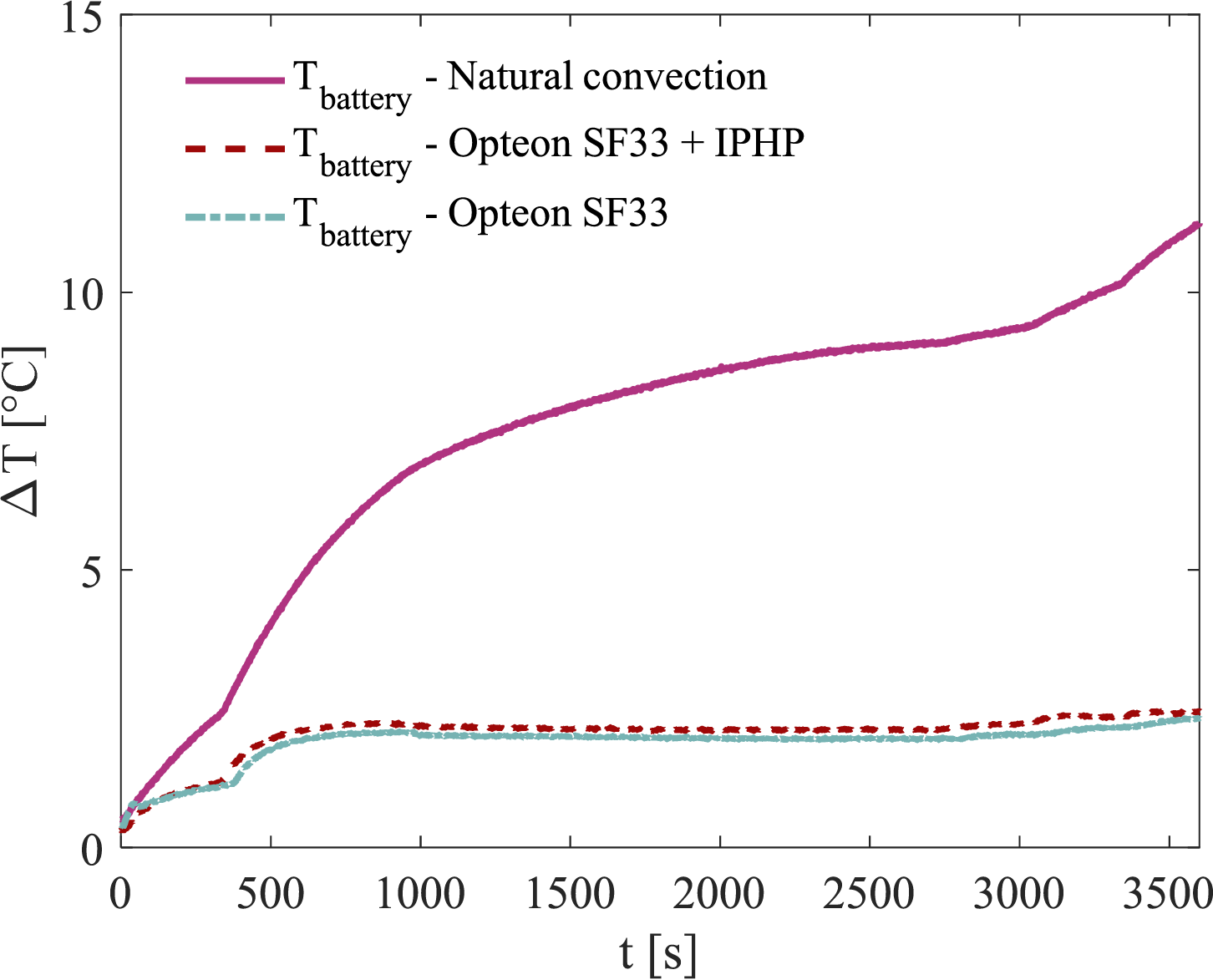
Figure 7: Maximum temperature difference inside the battery for the 3 considered configurations for 1C discharging
The findings from the 1C C-rate tests demonstrate that natural convection is insufficient to meet the thermal requirements of this battery system, necessitating more advanced BTMS solutions. Immersion cooling proves to be a highly effective alternative, offering a straightforward, entirely passive design capable of maintaining both the maximum temperature and internal temperature variation within acceptable ranges. However, the addition of the IPHP did not result in significant improvements despite increasing system complexity. At low power input levels and under favorable environmental conditions (such as an ambient temperature of 20°C), the heat generated by the battery is absorbed as sensible heat by the liquid phase of Opteon SF33 without reaching its boiling point, as shown in Fig. 5. As a result, vaporization is minimal, reducing the contribution of the IPHP, whose primary function is to facilitate the rapid recondensation of the dielectric fluid vapor.
The discharge process at a C-rate of 2C involves higher power, creating a more challenging condition for the three different cooling systems. Considering the maximum temperature reached by the battery, like the 1C test, natural convection cooling results in a temperature exceeding of the limit of 40°C. Specifically, as shown in Fig. 8, after only 103 s from the start of the discharge phase, the battery reaches a maximum temperature of 58°C, leading to an early test termination for safety reasons. The battery performs significantly better when immersed in Opteon SF33. In the configuration with only the dielectric fluid, the battery temperature rises more slowly than in natural convection, with a final phase where the increase is further reduced due to the beginning of the coolant’s phase change around 33.4°C at atmospheric pressure. The maximum temperature reached is 36.5°C, indicating that this cooling system meets the thermal management requirements for the battery.
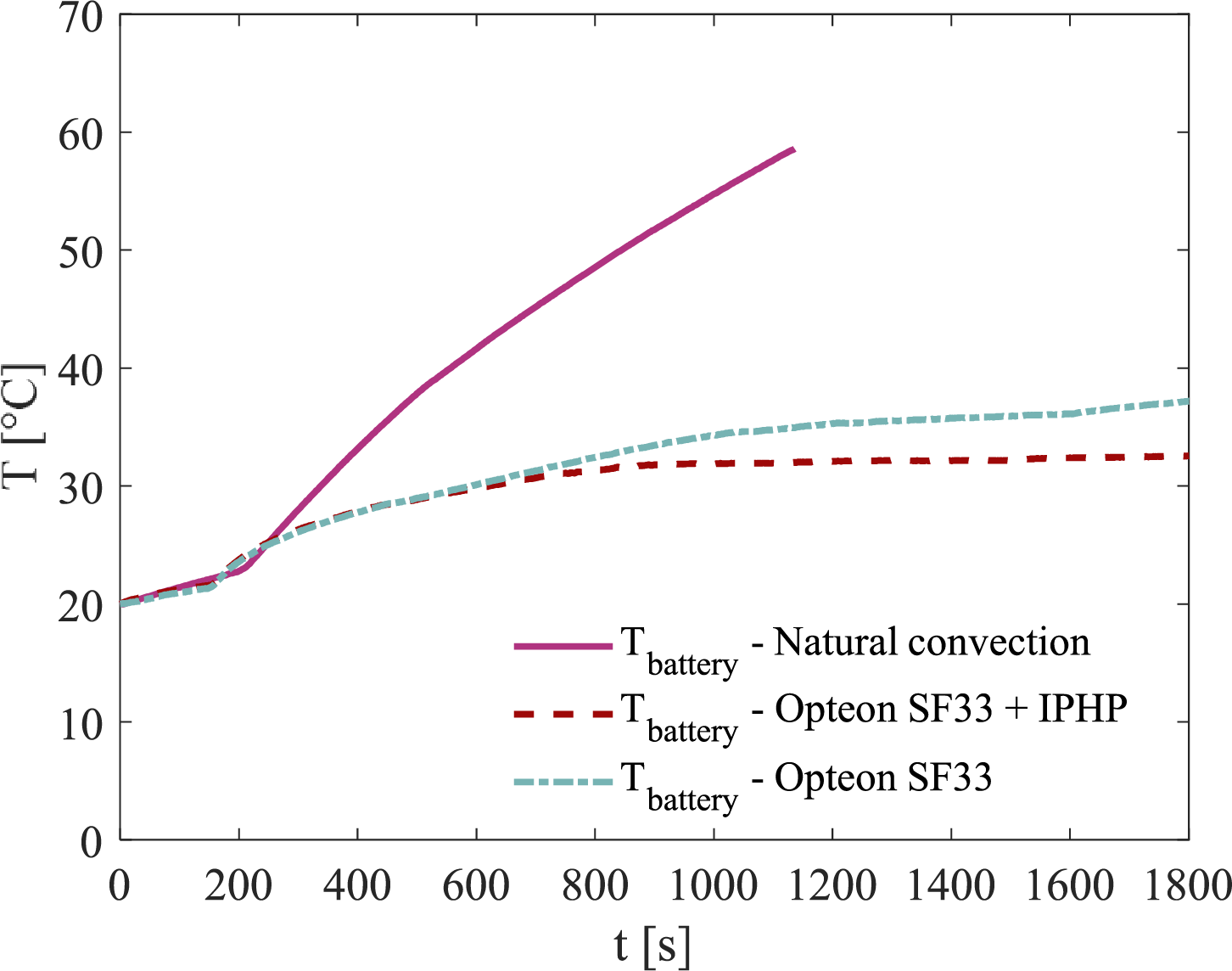
Figure 8: Maximum temperature measured at the battery for the 3 considered configurations for 2C discharging
However, under 2C discharging conditions, the best solution seems to be represented by the battery thermal management system proposed in the present work. The initial battery temperature rise is identical in both configurations with Opteon SF33. However, a clear difference appears after 600 s, as, with the cooling system using only Opteon, the temperature continues to rise, albeit at a slower rate. In contrast, when the IPHP is added, the temperature stabilizes and remains constant around 33°C. With the IPHP, the Opteon SF33 maintains a stable temperature, while the system with only the fluid shows an increasing temperature trend. The observed variation in fluid behavior can be largely attributed to the critical role played by the integrated pulsating heat pipe (IPHP) during high-power discharge cycles. As the liquid phase of Opteon SF33 reaches its boiling point, the rate of vaporization increases significantly. The presence of the IPHP facilitates efficient vapor condensation, ensuring stable internal pressure and preventing excessive fluctuations, as illustrated in Fig. 9. Moreover, the continuous dripping observed between the IPHP coil and the working fluid during testing (Fig. 10) provides compelling evidence of the system’s ability to effectively regulate the recondensation of dielectric fluid vapor. This dripping phenomenon signifies that the vaporized fluid undergoes rapid condensation, thereby maintaining a consistent circulation of the working fluid throughout the system. Such behavior is crucial for sustaining a stable thermal environment, especially under high-power discharge conditions where efficient heat dissipation is imperative. By preventing thermal runaway and minimizing temperature gradients, the IPHP enhances the overall reliability and performance of the system. The ability to maintain consistent thermal management ensures not only operational stability but also extends the longevity of components by mitigating thermal stress. These findings highlight the importance of advanced fluid solutions in optimizing high-power electronic, further reinforcing the value of incorporating IPHP technology for enhanced thermal control. In the cooling system with only Opteon SF33, insufficient condensation occurs on the box walls, the only surfaces available for heat exchange with the environment. As a result, the internal pressure continues to increase, reaching a maximum around 1.4 bar.
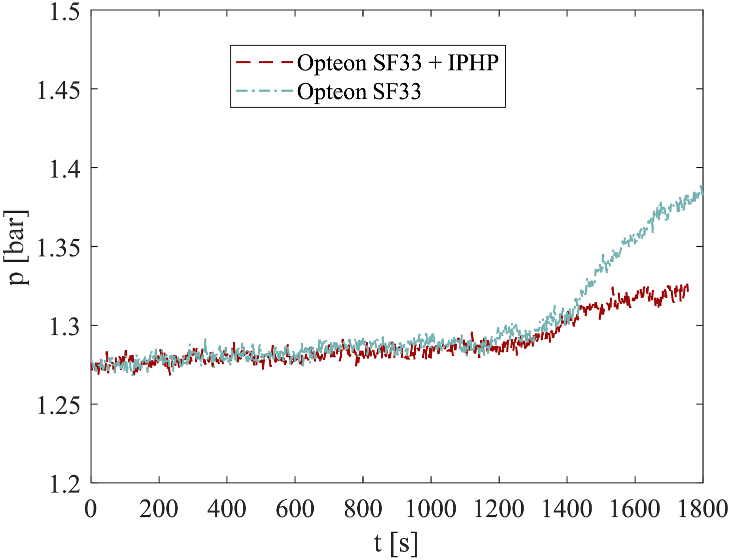
Figure 9: Pressure distribution vs time inside the box for 2C discharging
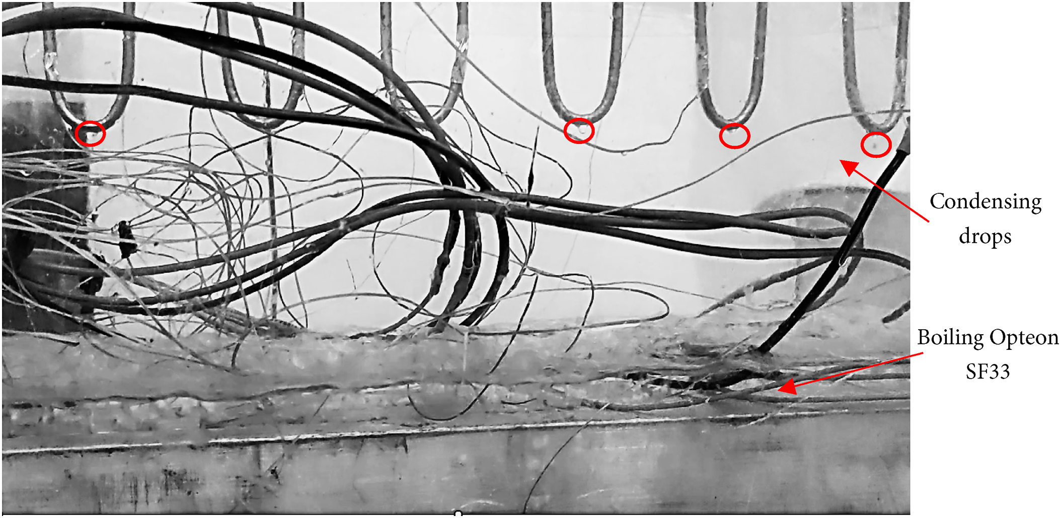
Figure 10: Condensing and boiling phenomena for 2C discharging
This data underscores the critical role of the PHP when the cooling fluid transitions into its vapor phase, particularly within a sealed environment. In such conditions, excessive evaporation and a reduction in the liquid phase can lead to a sudden escalation in both temperature and pressure. This rapid rise not only exposes the equipment’s functionality but also poses significant safety risks, such as system overheating or structural failure. By enhancing heat transfer efficiency and maintaining thermal equilibrium, the PHP serves as an essential component in preserving the reliability and longevity of the equipment, even under demanding thermal conditions.
It is also interesting to examine the temperature differences recorded within the battery. Under natural convection, an entirely unfavorable situation occurs, with a ΔT of more than 25°C measured after only half the test, clearly indicating the need for a more efficient BTMS (Fig. 11).
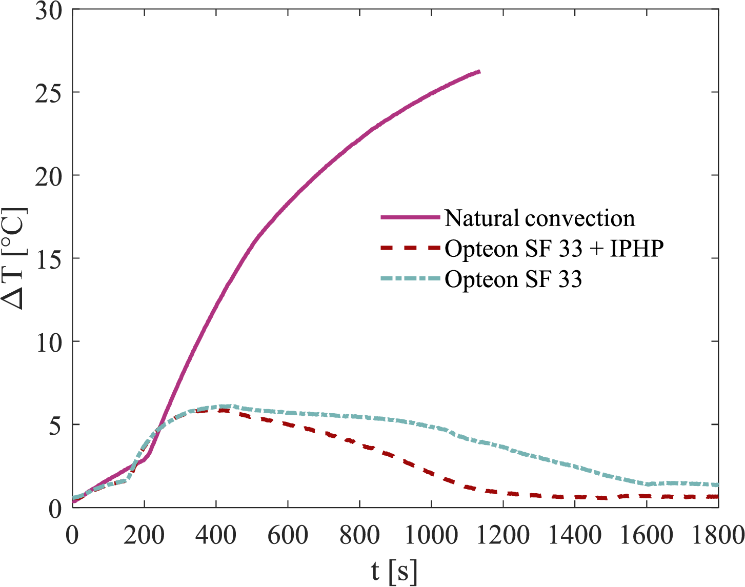
Figure 11: Maximum temperature difference inside the battery for the 3 considered configurations for 2C discharging
In the configuration with Opteon SF33, better results are obtained. In the initial phase, the temperature difference increases, reaching a value higher than that in the 1C test, at 6°C. However, as the phase change begins in the fluid, the internal battery temperature becomes increasingly uniform, with a ΔT around 1.3°C in the last 200 s. Thus, in this respect, the result is better than the lower-power test under the same cooling conditions. This battery behavior is further emphasized by the efficiency in the configuration using both Opteon SF33 and the IPHP. After an initial phase where the temperature difference rises to a ΔT of 6°C, it then drops drastically and remains constant at a temperature difference of less than one degree, specifically 0.6°C. This ensures thermal uniformity in the battery, avoiding internal hotspots due to the full immersion in fluid and its constant temperature during the phase change.
Evaluating the analyses of the results from the 2C C-rate tests in the three configurations, it can be concluded that, unlike the previous case, the inclusion of the IPHP provides better performance than the system that relies solely on immersion in the dielectric fluid. It enables greater temperature control, keeping the entire system at a lower, stable value. Safety is also improved, as the internal pressure does not tend to increase, which is crucial since the box is a closed volume. Additionally, the IPHP and Opteon SF33 system achieves excellent temperature uniformity within the battery, with even better values than in the 1C C-rate case. It can therefore be concluded that incorporating the IPHP at high power levels is essential for achieving better efficiency, and the designed BTMS demonstrates excellent performance under all usage conditions, keeping maximum temperature and uniformity within the limits required by the battery’s specifications.
The work focuses on the complex thermal management of lithium-ion batteries in electric vehicles, where maintaining the battery’s temperature between 20 and 40°C with a uniform temperature distribution is crucial. After an initial study and review of existing battery thermal management systems (BTMS) in the literature, a dual-phase cooling system was designed. Specifically, the low-boiling dielectric fluid Opteon SF33 was used for immersion cooling to leverage the latent heat released during the phase change. Supporting this, a two-phase heat exchanger of the PHP type was integrated into the system.
In this initial phase, a simplified version of the PHP was designed to assess the feasibility of the BTMS, and an experimental setup was developed for this system. Experimental trials and data analysis validated the effectiveness of the designed cooling system. The immersion in the dielectric fluid combined with the PHP successfully met the initial requirements by keeping the battery’s temperature within the optimal range of 20 to 40°C. Additionally, excellent temperature uniformity within the battery was achieved, particularly at higher power levels, thanks to the dielectric fluid’s phase change and total immersion. The measured temperature difference remained consistently below the threshold for lithium-ion batteries, staying under 5°C.
The addition of the ideal PHP proved to be beneficial as it allowed for improved temperature and pressure control. Compared to a system relying solely on dielectric fluid, the presence of the IPHP enables more efficient heat dissipation, especially at high power levels, by facilitating faster condensation of the evaporated dielectric fluid. Moreover, the insertion of the IPHP allows more effective pressure control: this plays an essential role in system safety, as it reduces the risk of excessive increase of internal pressure, which could lead to serious security issues. In conclusion, by maintaining a balanced and stable operating environment, the IPHP enhances the overall reliability and safety of the system. The results suggest that the design is sound, and that further work should address system improvements identified during testing. The next step in optimizing the cooling system is to replace the aluminum equivalent setup with an actual lithium-ion battery module to obtain more precise measurements of the system’s cooling efficiency under real operating conditions. This transition will provide a more accurate representation of the thermal behavior of a functional battery pack, allowing for a deeper analysis of heat dissipation and temperature uniformity. In addition, integrating a real battery module also introduces new challenges. Unlike aluminum plates with heaters, which provide a controlled and uniform heat source, pouch cells in a real battery pack may exhibit varying thermal behaviors during the discharge phase. Differences in internal resistance, electrochemical reactions, and cell positioning could lead to uneven heat generation, making it more difficult to achieve consistent temperature regulation. Addressing these complexities will be crucial in developing an effective and reliable battery thermal management system. Another promising modification is to replace the ideal PHP with an actual PHP, ideally with an increased heat exchange area compared to the tested structure. This change could lead to a fully passive cooling system, eliminating the energy losses associated with active components.
Finally, optimizing the box size is important to reduce BTMS dimensions and facilitate easier application in the automotive sector. In line with this goal, optimizing the amount of dielectric fluid used is essential, as testing showed that even at higher power levels, the liquid level remained almost unchanged, indicating an excess of fluid in the case. Given the satisfactory results, a potential future step would be to test the fully passive dual-phase cooling system on an actual electric vehicle.
Acknowledgement: Not applicable.
Funding Statement: This research was granted by National Recovery and Resilience Plan (NRRP) Mission 4 Component 2 Investment 1.5—Call for tender No. 3277 of 30/12/2021 of Italian Ministry of University and Research funded by the European Union–NextGenerationEU (Award Number: Project code ECS00000033, Concession Decree No. 1052 of 23 June 2022 adopted by the Italian Ministry of, CUP D93C22000460001, “Ecosystem for Sustainable Transition in Emilia-Romagna” (Ecosister)).
Author Contributions: Conceptualization, Luca Cattani and Fabio Bozzoli; methodology, Luca Cattani; software, Federico Sacchelli and Matteo Malavasi; validation, Federico Sacchelli, Matteo Malavasi and Luca Cattani; formal analysis, Luca Cattani and Fabio Bozzoli; investigation, Federico Sacchelli, Matteo Malavasi and Luca Cattani; resources, Luca Cattani; data curation, Federico Sacchelli; writing—original draft preparation, Luca Cattani and Federico Sacchelli; writing—review and editing, Fabio Bozzoli and Corrado Sciancalepore; visualization, Federico Sacchelli; supervision, Luca Cattani and Fabio Bozzoli; project administration, Luca Cattani; funding acquisition, Luca Cattani. All authors reviewed the results and approved the final version of the manuscript.
Availability of Data and Materials: The data that support the findings of this study are available from the corresponding author, Fabio Bozzoli, upon reasonable request.
Ethics Approval: Not applicable.
Conflicts of Interest: The authors declare no conflicts of interest to report regarding the present study.
References
1. Mohammadi F, Saif M. A comprehensive overview of electric vehicle batteries market. e-Prime-Adv Electr Eng Electron Energy. 2023;3(4):100127. doi:10.1016/j.prime.2023.100127. [Google Scholar] [CrossRef]
2. Manzetti S, Mariasiu F. Electric vehicle battery technologies: from present state to future systems. Renew Sustain Energy Rev. 2015;51(48):1004–12. doi:10.1016/j.rser.2015.07.010. [Google Scholar] [CrossRef]
3. Arun V, Kannan R, Ramesh S, Vijayakumar M, Raghavendran PS, Siva Ramkumar M, et al. Review on Li-ion battery vs nickel metal hydride battery in EV. Adv Mater Sci Eng. 2022;2022:7910072–7. doi:10.1155/2022/7910072. [Google Scholar] [CrossRef]
4. Gayathri A, Manimegalai V, Krishnakumar P. Challenging issues and solutions on battery thermal management for electric vehicles. In: Tripathi SL, Alvi PA, Subramaniam U, editors. Electrical and electronic devices, circuits, and materials: technological challenges and solutions. Hoboken, NJ, USA: John Wiley & Sons, Inc.; 2021. p. 535–53. doi: 10.1002/9781119755104.ch28. [Google Scholar] [CrossRef]
5. Berg H. Batteries for electric vehicles: materials and electrochemistry. Cambridge, UK: Cambridge University Press; 2015. [Google Scholar]
6. Pesaran A, Santhanagopalan S, Kim GH. Addressing the impact of temperature extremes on large format Li-ion batteries for vehicle applications. In: Proceedings of the 30th International Battery Seminar; 2013 Mar 10–14; Ft. Lauderdale, FL, USA. [Google Scholar]
7. Wang X, Liu S, Zhang Y, Lv S, Ni H, Deng Y, et al. A review of the power battery thermal management system with different cooling, heating and coupling system. Energies. 2022;15(6):1963. doi:10.3390/en15061963. [Google Scholar] [CrossRef]
8. Nelson P, Dees D, Amine K, Henriksen G. Modeling thermal management of lithium-ion PNGV batteries. J Power Sources. 2002;110(2):349–56. doi:10.1016/S0378-7753(02)00197-0. [Google Scholar] [CrossRef]
9. Huo Y, Rao Z, Liu X, Zhao J. Investigation of power battery thermal management by using mini-channel cold plate. Energy Convers Manag. 2015;89:387–95. doi:10.1016/j.enconman.2014.10.015. [Google Scholar] [CrossRef]
10. An Z, Jia L, Li X, Ding Y. Experimental investigation on lithium-ion battery thermal management based on flow boiling in mini-channel. Appl Therm Eng. 2017;117(2):534–43. doi:10.1016/j.applthermaleng.2017.02.053. [Google Scholar] [CrossRef]
11. Wang Y, Li C, Wen X, Cai W, Jiang Y, Wen C, et al. Experimental studies on two-phase immersion liquid cooling for Li-ion battery thermal management. J Energy Storage. 2023;72:108748. doi:10.1016/j.est.2023.108748. [Google Scholar] [CrossRef]
12. Hirano H, Tajima T, Hasegawa T, Sekiguchi T, Uchino M. Boiling liquid battery cooling for electric vehicle. In: Proceedings of the 2014 IEEE Conference and Expo Transportation Electrification Asia-Pacific (ITEC Asia-Pacific); 2014 Aug 31–Sep 3; Beijing, China. doi:10.1109/ITEC-AP.2014.6940931. [Google Scholar] [CrossRef]
13. Zhu L, Boehm RF, Wang Y, Halford C, Sun Y. Water immersion cooling of PV cells in a high concentration system. Sol Energy Mater Sol Cells. 2011;95(2):538–45. doi:10.1016/j.solmat.2010.08.037. [Google Scholar] [CrossRef]
14. Roe C, Feng X, White G, Li R, Wang H, Rui X, et al. Immersion cooling for lithium-ion batteries—a review. J Power Sources. 2022;525(2):231094. doi:10.1016/j.jpowsour.2022.231094. [Google Scholar] [CrossRef]
15. Duan X, Naterer GF. Heat transfer in phase change materials for thermal management of electric vehicle battery modules. Int J Heat Mass Transf. 2010;53(23–24):5176–82. doi:10.1016/j.ijheatmasstransfer.2010.07.044. [Google Scholar] [CrossRef]
16. Wang J, Gan Y, Liang J, Tan M, Li Y. Sensitivity analysis of factors influencing a heat pipe-based thermal management system for a battery module with cylindrical cells. Appl Therm Eng. 2019;151:475–85. doi:10.1016/j.applthermaleng.2019.02.036. [Google Scholar] [CrossRef]
17. Cattani L, Malavasi M, Bozzoli F, D’Alessandro V, Giammichele L. Experimental analysis of an innovative electrical battery thermal management system. Energies. 2023;16(13):5071. doi:10.3390/en16135071. [Google Scholar] [CrossRef]
18. Lee JS, Kim SJ, Han WS, Rhi SH. Anti-gravity 3D pulsating heat pipe for cooling electric vehicle batteries. Energies. 2024;17(10):2283. doi:10.3390/en17102283. [Google Scholar] [CrossRef]
19. Buidin TIC, Mariasiu F. Battery thermal management systems: current status and design approach of cooling technologies. Energies. 2021;14(16):4879. doi:10.3390/en14164879. [Google Scholar] [CrossRef]
20. Khandekar S, Groll M. On the definition of pulsating heat pipes: an overview. In: Proceedings of Fifth Minsk International Seminar Heat Pipes, Heat Pumps, Refrigerators; 2003 Sep 8–11; Minsk, Belarus. [Google Scholar]
21. Pagliarini L, Cattani L, Mameli M, Filippeschi S, Bozzoli F, Rainieri S. Global and local heat transfer behaviour of a three-dimensional pulsating heat pipe: combined effect of the heat load, orientation and condenser temperature. Appl Therm Eng. 2021;195(12):117144. doi:10.1016/j.applthermaleng.2021.117144. [Google Scholar] [CrossRef]
22. Mohseni P, Husev O, Vinnikov D, Strzelecki R, Romero-Cadaval E, Tokarski I. Battery technologies in electric vehicles: improvements in electric battery packs. IEEE Ind Electron Mag. 2023;17(4):55–65. doi:10.1109/MIE.2023.3252265. [Google Scholar] [CrossRef]
23. Bernardi D, Pawlikowski E, Newman J. A general energy balance for battery systems. J Electrochem Soc. 1985;132(1):5–12. doi:10.1149/1.2113792. [Google Scholar] [CrossRef]
24. Jindal P, Katiyar R, Bhattacharya J. Evaluation of accuracy for Bernardi equation in estimating heat generation rate for continuous and pulse-discharge protocols in LFP and NMC based Li-ion batteries. Appl Therm Eng. 2022;201(2):117794. doi:10.1016/j.applthermaleng.2021.117794. [Google Scholar] [CrossRef]
Cite This Article
 Copyright © 2025 The Author(s). Published by Tech Science Press.
This work is licensed under a Creative Commons Attribution 4.0 International License , which permits unrestricted use, distribution, and reproduction in any medium, provided the original work is properly cited.
 Downloads
 Citation Tools