
 Submit a Paper
 Propose a Special lssue
 Open Access
ARTICLE

Two-Dimensional Mathematical Modeling of Gas Hydrate Dissociation with a Nonlinear Forchheimer-Type Filtration Law
1 Department of Mathematics and Computer Science, Faculty of Science, Damanhour University, Damanhour, 22511, Egypt
2 Shirshov Institute of Oceanology of Russian Academy of Sciences, Moscow, 117997, Russia
3 Keldysh Institute of Applied Mathematics of Russian Academy of Sciences, Moscow, 125047, Russia
* Corresponding Author: Viktoriia Podryga. Email:
(This article belongs to the Special Issue: Heat Transfer Analysis and Optimization in Energy Systems)
Frontiers in Heat and Mass Transfer 2025, 23(5), 1575-1593. https://doi.org/10.32604/fhmt.2025.067097
Received 25 April 2025; Accepted 29 July 2025; Issue published 31 October 2025
 View Full Text
 Download PDF
Abstract
The work considers the problem of gas hydrate dissociation in a porous medium using the two-term Forchheimer law, corresponding to high flow rates of reservoir fluids. Such rates can arise during the decomposition of gas hydrates, since a large amount of gas is released. Intensive emissions of gases from the earth’s interior are observed on the ocean floor. They are also associated with a large number of subvertical geological structures under the ocean floor, coming to the surface in the form of local ring funnels (pockmarks). Many similar objects have also been found on land. Particular interest in this problem is caused by climate threats associated with the release of greenhouse gases. The movement of gas released from the hydrate to the breakthrough channel is similar to the gas inflow to the well (without hydrate), which is usually described by a two-term filtration law. In this work, a mathematical model of gas hydrate dissociation with a nonlinear Forchheimer-type law of motion is developed. The system is split in two blocks by physical processes, taking into account the quadratic correction to the velocity in the filtration law. The first block is responsible for the convective transfer of saturation parameters in the model, water, gas and hydrate saturations are taken into account. The second block corresponds to the equation of dissipative piezoconductivity with a different number of thermodynamic degrees of freedom, taking into account heat and mass transfer in a porous medium. The performed splitting allows using explicit-implicit difference schemes when solving problems and avoiding strong refinement of the step in time and space. For numerical modeling, the support operator method is used, which makes it possible to discretize partial differential equations on irregular grids, which allows taking into account the complex geometry and lithology of the reservoir. A difference scheme based on the support operator method is developed, which, due to the mutually consistent approximation of vector analysis operations (divergence and gradient), allows to take into account the various flux laws between adjacent grid cells, including quadratic corrections to the velocity. Based on the developed numerical algorithms and their program implementations, calculations of gas hydrate dissociation are performed both in a reservoir of simple geometric structure and in a heterogeneous reservoir of complex configuration. The results obtained correspond to the physics of the processes under consideration.Keywords
Gas hydrate deposits are one of the potential sources of natural gas, which is necessary for energy industry. Gas hydrates are solid clathrate ice-like structures, in which gas molecules are located in the cavities of the crystal lattice formed by water molecules due to hydrogen bonds [1]. They are stable only in certain ranges of temperature and pressure. Such conditions are realized in the World Ocean in many areas of continental shelves, on the slopes of marginal or inland seas. Therefore, significant quantities of gas hydrates can accumulate in the sedimentary layer of these areas. Gas hydrates can also form and persist on land in permafrost zones. Changes in the external conditions (temperature, pressure) can lead to the decomposition of gas hydrates with a significant release of gas (approximately 160 volumes of gas per one volume of hydrate). The released gas will rise up through the pores and cracks of sedimentary rocks, reaching the earth’s surface, and will either rush into the atmosphere (in marine conditions—to the surface of the bottom and go into the water column), or accumulate under the fluid seal. With further release of gas, it is capable of breaking through the fluid seal. This occurs either in the form of seepage through a system of pores and cracks, or in the form of a sharp explosive destruction of the rock with the formation of a breakthrough channel. In nature, both cases are observed, as well as all sorts of intermediate options. Significant gas emissions, called gas seeps, have been discovered on the ocean floor. They appear in the water as fountains of bubbles. In most cases, these fountains are meters or tens of meters wide, but sometimes reach several hundred meters in diameter. Seeps often form extensive fields or linear structures concentrated near faults. They have been discovered in many areas of the World Ocean. A detailed review as of 2007 year is given in Ref. [2]. Since then, a significant number of works have been devoted to the study of underwater gas emissions, studying specific regions. Many new areas where gas seeps form have been found, their properties have been studied, and several mechanisms have been proposed to explain their origin. Typical examples of works related to the study of gas flows in different areas of the World Ocean are Refs. [3–5]. In these works, as in many others, one of the possible causes of the formation of methane seeps is assumed to be the decomposition of gas hydrates. Several geological, geophysical and other arguments are given in favor of this hypothesis, but contradictory arguments are also found, so the issue remains debatable, and mathematical modeling may be useful for determining the truth.
Other natural objects, also apparently associated with the release of gas from the earth’s interior, are funnel-shaped depressions (pockmarks), found in large numbers on the bottom of seas and lakes, under which subvertical geological structures are located. It is assumed that in most cases these structures arise as a result of a sharp release of gas, the origin of which in many cases is associated with the dissociation of gas hydrates. The study of pockmarks is devoted to an extensive literature, in which this issue is often studied in conjunction with methane seeps, both Ref. [2] and in a large number of modern works devoted to the study of specific regions in which an increasing number of pockmark fields are found on the bottom of lakes and seas. Typical examples of such works are Refs. [6–8] and many others. Even the indicated works show the wide distribution of pockmarks and gas seeps, and this is only a small part of the overall picture. A significant number of similar objects have been found on land. In the permafrost zone of Yamal, more than 20 giant craters have been discovered, the origin of which most researchers associate with gas emissions, which corresponds to the general geological structure of the north of Western Siberia, characterized by several thousand areas of powerful gas emissions from the bottom of reservoirs, thermokarst lakes, and mud volcanism that have been identified to date [9]. The origin of the released gas is being studied. It is assumed that some of this gas may be associated with gas hydrates. Physical models of the influence of melt lakes on the dissociation of gas hydrates and explosive gas emissions are being constructed [10]. Methods are being developed for calculating the processes leading to explosive gas release and the formation of craters [11].
In Ref. [12], numerical modeling of methane migration from deep horizons in the Ross Sea in Antarctica was performed based on a mathematical model of gas hydrate dissociation in a porous medium under Darcy’s law. It showed that the hydrate stability zone is not necessarily a barrier for gas rising from the depths, and that it is capable of passing through it without forming a hydrate and reaching the seabed. However, Darcy’s law is not always applicable in problems of this type. The above results show that gas movement during gas hydrate dissociation often occurs at high velocity.
The gas movement during dissociation of gas hydrates often occurs at a high velocity. For such flows in porous and fractured-porous media, Darcy’s law, usually used to describe filtration, is not applicable. Fluid movement in such cases obeys a nonlinear filtration law. There are many works devoted to the definition of such a law. Since the deviation from linearity is influenced by various factors, such as flow velocity, possible turbulence, geometry of pore channels, a single form of such a law has not been established. A review of several options proposed over many decades is given in Ref. [13]. A critical review of possible approaches to the problem and a significant number of modern works is given in Ref. [14]. Research in this direction continues. The most widely used is the two-term Forchheimer law [15], proposed in 1901 and since then widely discussed in scientific literature and actively used in practice, especially for studying flows in the bottomhole zone of gas wells, where high filtration rates can be achieved. This also applies to wells drilled in a gas hydrate-containing formation. In addition, the analog of the bottomhole zones in problems related to the dissociation of gas hydrates are the areas of gas inflow to the channels through which it rises upward.
In most works, the nonlinearity of the filtration law is taken into account only for near-well zones. However, there are research results [16] showing that in many cases it must be taken into account on the scale of the entire reservoir. This confirms the importance of constructing a computational model that allows such calculations to be made, including taking into account gas hydrates.
Forchheimer’s law for single-phase filtration in the isotropic case has the following form [13]:
where p is the pressure,
To obtain specific values of the coefficients included in the recording of this law, to study their relationship with the structure of the porous medium, data obtained during field development, well testing, etc., are processed and physical and mathematical modeling is used. Since porous media have different internal structures, differ in the degree of randomness of the arrangement and size of the frame particles, the tortuosity of the pore channels, different dependencies are obtained for different types of media, while in many cases preserving a single structure resulting from the analysis of dimensionality and other general physical principles. Many works are devoted to this problem. The coefficients are found experimentally [17], as well as theoretically by studying micromodels of the porous medium, flow in individual channels, from where, by averaging both with the help of mathematical approaches and on the basis of numerical modeling, and methods of continuum mechanics, the transition to the macrolevel is carried out (for example, Refs. [18,19]). Nonlinear filtration laws are also studied for fractured-porous media [20].
A summary of some results on establishing the type of dependence of the coefficients on the parameters of the porous medium is given in Ref. [13], and a review of later results is presented in Refs. [17,21]. A summary table with the coefficients values for the Forchheimer law experimentally obtained in several works can be seen in Ref. [22]. Also, in many works an intermediate law between the Darcy and Forchheimer laws is used, proposed in Ref. [23].
There are extensions of Forchheimer’s law to non-single-phase filtration. Various modifications of the basic equations are considered. In particular, there is a variant of direct generalization of Eq. (1) to the multiphase case, similar in construction method to the introduction of phase permeabilities into Darcy’s law [24]. In this case, the filtration law in the isotropic case, neglecting capillary forces, has the form [25]:
where the index
From Eqs. (1) and (2), it is evident that the quadratic correction to the velocity leads to the necessity of increasing the pressure gradients in comparison with Darcy’s law (without the quadratic term) to obtain the given velocity. The influence of this effect on the release of gas from gas hydrates, its movement in a porous medium and emission from the earth’s surface or the ocean floor can manifest itself in different ways: on the one hand, it can lead to a slower movement at a given pressure gradient, and on the other hand, due to this slowness, it can lead to a greater increase in pressure during the decomposition of hydrates and the possibility of more active destruction of the porous medium with the formation of cracks along which the gas will move faster. Also, a significant increase in pressure can cause an explosive release of gas and the formation of a crater. Numerical modeling taking into account the two-term filtration law will make it possible to quantitatively take these effects into account. The issues of formation destruction are not considered in this work, but the calculation of the pressure change is a necessary component for this.
When solving problems of underground fluid dynamics, including those taking into account gas hydrates, methods of continuum mechanics are usually used, based on the laws of conservation of mass, momentum (in these problems expressed as the filtration law) and energy. In problems of multiphase multicomponent filtration with phase transitions, this results in complex nonlinear systems of partial differential equations of a mixed type (parabolic for pressures and hyperbolic for water and hydrate saturations against the background of a fixed velocity field associated with the pressure gradient). For the numerical solution of such equations, splitting by physical processes into the equations relative to the saturations of one or several phases and the equation for pressure is used [26–28]. In order to create effective numerical approaches and adequately describe each type of variable, splitting by physical processes is also used in this work.
Since the geological and lithological structure of regions where underground fluids flow is usually quite complex, characterized by heterogeneity of rocks in terms of reservoir properties, curvature of formations, the presence of sections with different characteristic dimensions (from a well or crack to a formation), it is necessary to develop numerical methods that allow modeling filtration processes taking this complexity into account. One of such methods is the support operator method, also called the mimetic finite difference method [29,30], which makes it possible to use irregular grids for numerical modeling that take into account the geometry and lithology of formations in detail. When it is used in a difference model, the conservation laws underlying the description of filtration processes remain valid. This becomes possible as a result of specially developed methods for discretization of differential gradient and divergence operators. The result is a technique for grid approximation of fluxes. It allows to include the filtration laws in a single scheme. These laws that can be different for each grid node, and in the case of anisotropy—also for the direction. A similar approach has already been used to model the decomposition of gas hydrates in low-permeability reservoirs, where the law of filtration with a limiting pressure gradient is satisfied [31].
2 Problem Statement and Basic Equations
The system of equations for the dissociation of a gas hydrate in a porous medium in the hydrate equilibrium zone is constructed on the basis of balance relations for mass and energy and without taking into account capillary forces has the form:
where
Eqs. (3) and (4) correspond to the continuity equations for water and gas, Eq. (5) to the energy equation.
The enthalpy of a gas hydrate unit mass can be expressed as the sum of the enthalpies of the components (gas and water) taking into account the latent heat of the phase transition. This is represented by the equation:
where
The phase equilibrium relationship for the hydrate is:
where A and B are empirical constants. Using expression (6), the dependence of the parameters on T can be reduced to the dependence on P.
Thus, P,
The system of Eqs. (3)–(5) is closed using Formula (2), corresponding to Forchheimer’s law.
To solve the system of equations, a splitting by physical processes is made, which is carried out using transformations similar to those given in Ref. [27]. As a result, the system is divided into two blocks (dissipative-piezoconductive for pressure and convective for the transfer of water and hydrate saturations), but with filtration velocities described by Formula (2).
The block responsible for dissipative processes, which in this case correspond to the pressure propagation, is obtained from Eq. (5), in which, using Eqs. (3) and (4), the water saturation
The coefficients of the Eq. (7) are differential operators or algebraic expressions of the initial variables. Here
where the expression
The operators
In Eq. (7), with coefficients (8)–(11), water saturation
The second block consists of Eqs. (3) and (4). It is hyperbolic and describes the transfer of water and hydrate saturations against the background of a fixed velocity field.
The initial conditions consist of specifying the pressure, water and hydrate saturations at the initial moment of time. The temperature is expressed through the pressure using Formula (6).
The boundary conditions depend on the physical formulation of the problem [26]. For pressure, boundary conditions of the Dirichlet, Neumann or mixed types can be used. For water and hydrate saturations, the method of characteristics is used to determine at which boundaries their values should be specified and at which they should not. The principle of such a choice is presented in Section 3. For the case of impermeability conditions, zero fluxes are specified at the boundary.
3 Monotonization Analysis of Forchheimer’s Laws for Water and Gas
In the case of
Forchheimer’s law for the filtration velocity of water and gas in isotropic form (2) can be written in the following form:
Here
The velocity modulus estimate is determined from the following equation, obtained from Eq. (12):
Next, we obtain the following quadratic equation from Eq. (13):
Solving a quadratic equation of the following type
where
For small
To express the velocity, we obtain from Eq. (12) Forchheimer’s law in the following form:
And to estimate the monotonicity with respect to
Let us rewrite Eq. (17) in a more convenient form:
When
Let’s calculate
We obtain the final expression:
From this we see that if for
4 Numerical Algorithms for Solving Filtration Problems with Gas Hydrate Inclusions on Irregular Grids for Models with the Forchheimer Law
For two-dimensional metric grids of the support operator method (SOM) [29], structures consisting of quadrangular and triangular cells (
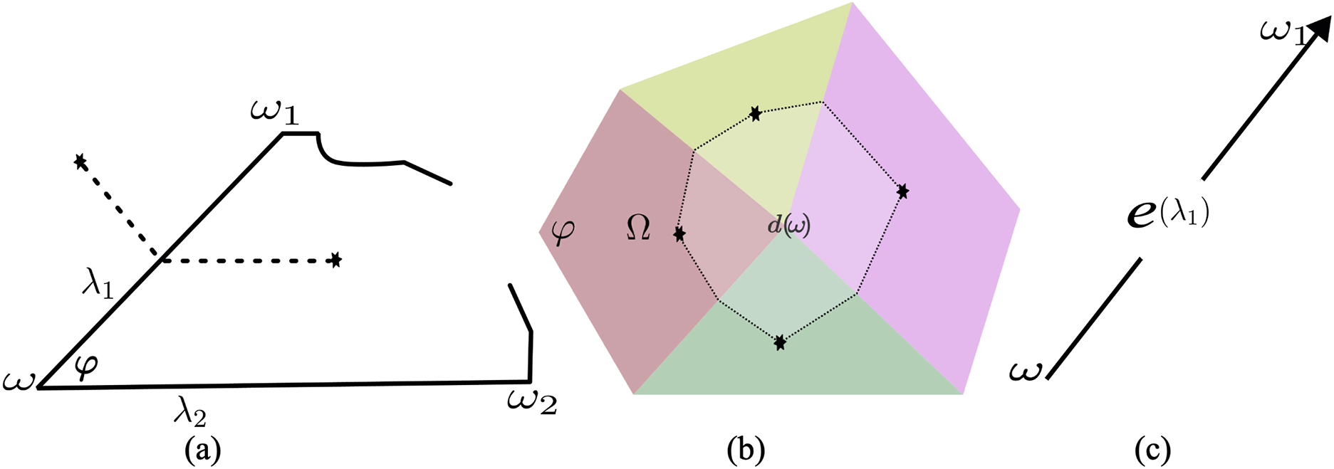
Figure 1: Metric grids. The symbol “*” denotes the centroid points of cells (
Let’s consider a grid
The discrete form of Eqs. (3)–(5) for conservation of the mass of the water and gas components and the total internal energy of the system (water, gas, hydrate, skeleton) can be represented as follows:
Here the quantities
When approximated in the grid basis
In the given expressions, the notation
When constructing the computational scheme, the complete difference system of Eqs. (19), (20) and (22) is split by physical processes. The block of saturation transfer Eqs. (19) and (20) at fixed filtration velocities and the piezoconductive-dissipative equation presented below are obtained.
In the expression
Thus, the developed numerical scheme includes two interrelated blocks of equations corresponding to splitting by physical processes. The first block (23)–(27) is parabolic and represents the equation of piezoconductivity for pressure, which comprehensively takes into account mass transfer, energy components (internal energies of phases and skeleton), and work performed by pressure. The second block (19) and (20) is hyperbolic and models the transfer of water saturation
As a model example, we chose a two-dimensional problem of gas hydrate decomposition near a small hole corresponding to a well or gas breakthrough channel, discussed in the Introduction. It is in the vicinity of such openings that high flow velocities may occur, at which it is necessary to take into account the nonlinearity of the filtration law; therefore, when studying the flow near wells, a two-term filtration law is widely used [32]. In the work, calculations are performed on a non-uniform two-dimensional grid condensing towards the hole. Such a model allows us to identify the main physical properties of the process, and also to demonstrate the capabilities of the method for calculating processes using grids with sharply changing cell sizes.
Since a model example is being considered, gas is assumed to be ideal, water incompressible:
Here M is the molar mass of the gas, R is the universal gas constant.
The characteristic values of the parameters are selected as follows [28]:
Here
Two models are considered: a) with Forchheimer’s filtration law; b) with Darcy’s law of motion. In the introduction it was noted that for the parameters
The computational domain in shown in Fig. 2 and consists of a circular ring bounded by two concentric circles, where the radius of the inner circle is
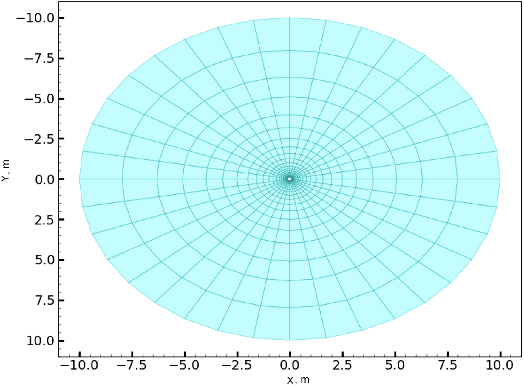
Figure 2: Computational domain
Initial conditions are the following:
Boundary conditions are as follows. At each node of the inner circular boundary, starting from the time
The calculations were carried out with a constant time step
6 Calculation Results and Their Analysis
The resulting pressure differences and associated temperature are the driving force for hydrate formation and its potential dissociation. Since in the model problem under consideration the pressure difference is large and the region is small, the processes proceed rapidly.
Fig. 3 shows the pressure distribution at
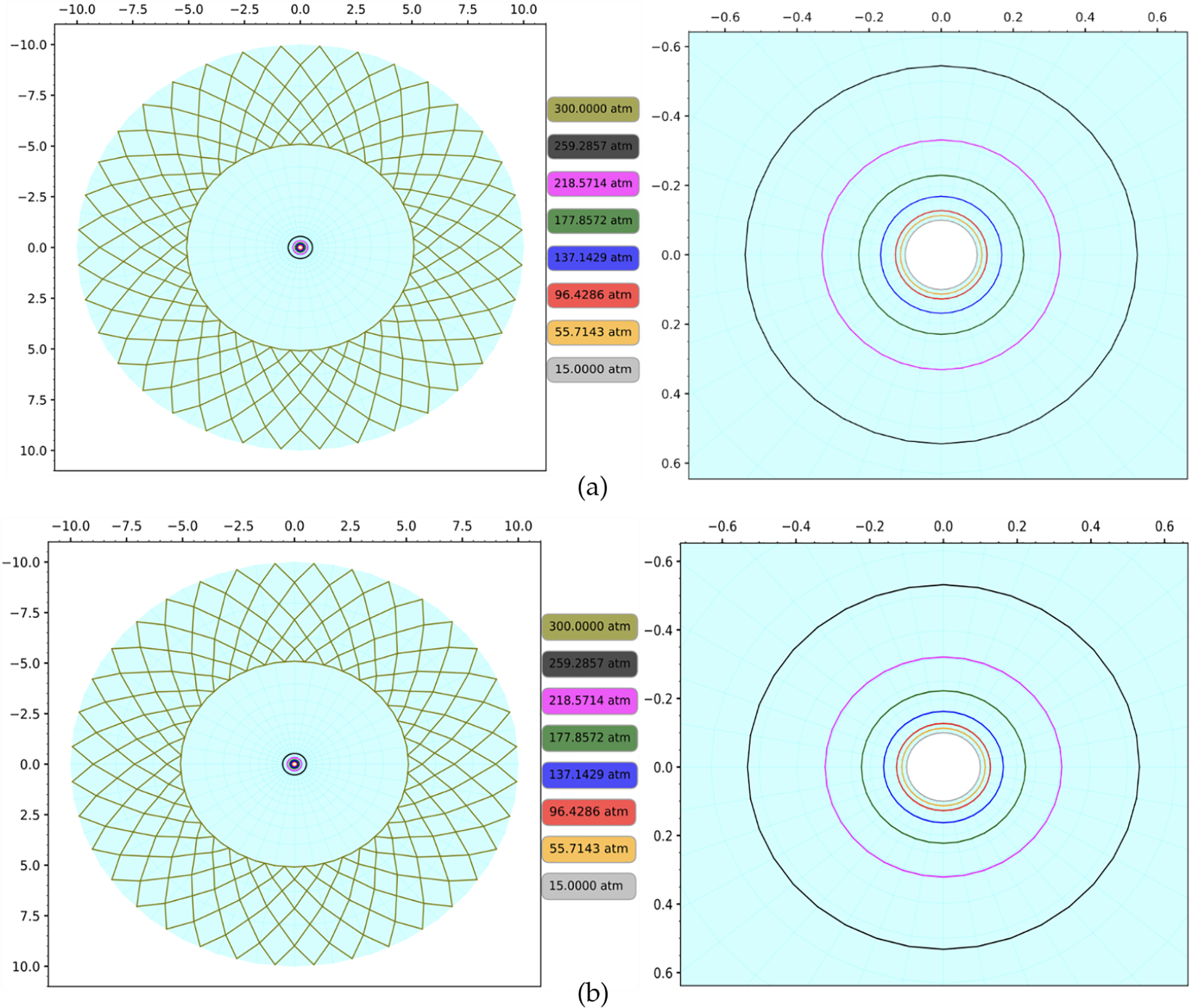
Figure 3: Pressure distribution at
The qualitative pictures are similar. To determine the quantitative difference, the changes in parameters along the radial section are considered, the choice of which is shown in Fig. 4. There are also indicated grid nodes with numbers 516, 483, 448, 412, 376 and 154, for which a detailed study of the process dynamics is carried out, reflected in Figs. 5–7.
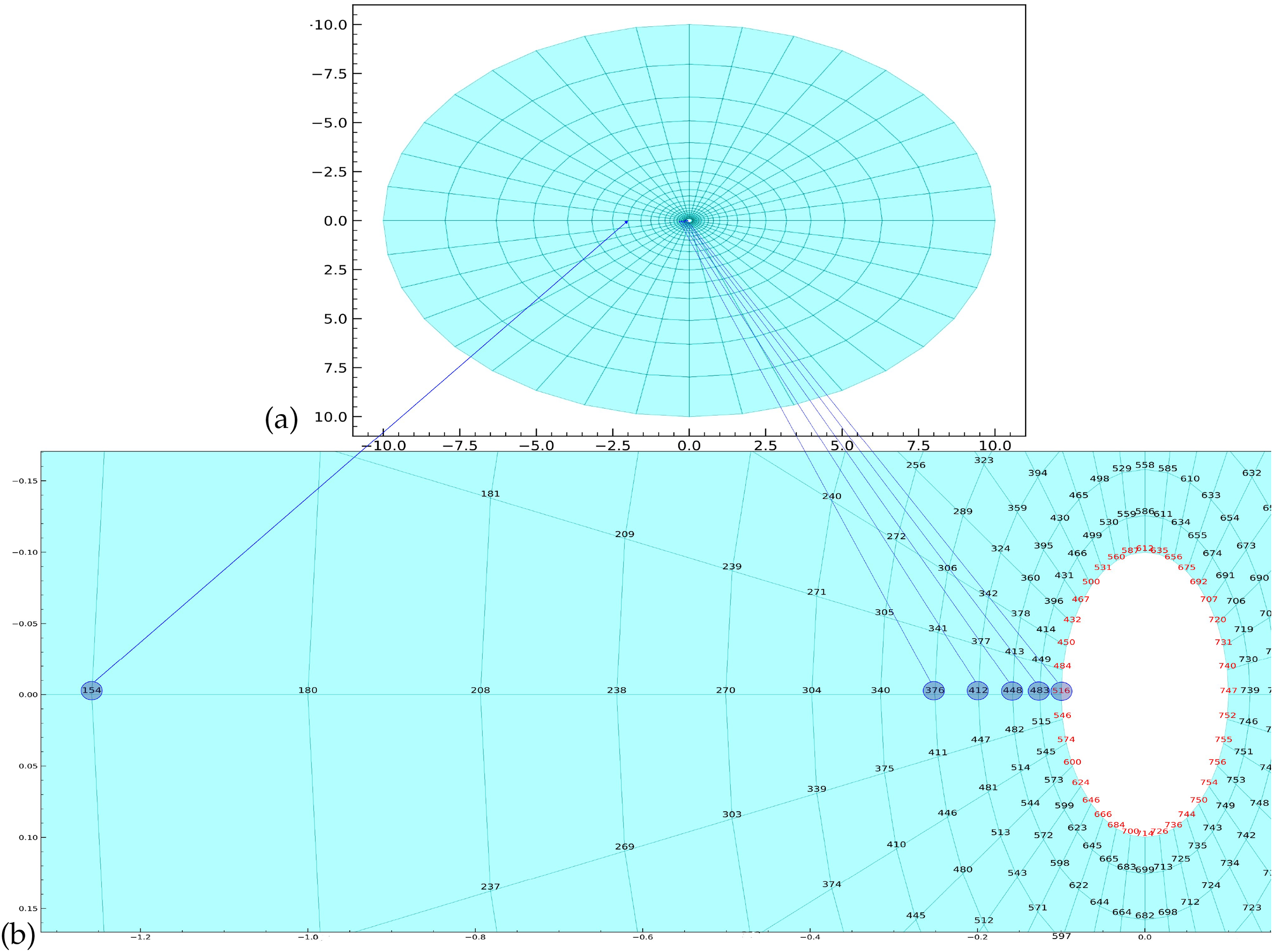
Figure 4: The overall modeling area (a) and the selection of the radial section and grid nodes for which the graphs are built (b). The blue circles highlight grid nodes with numbers 516, 483, 448, 412, 376 and 154
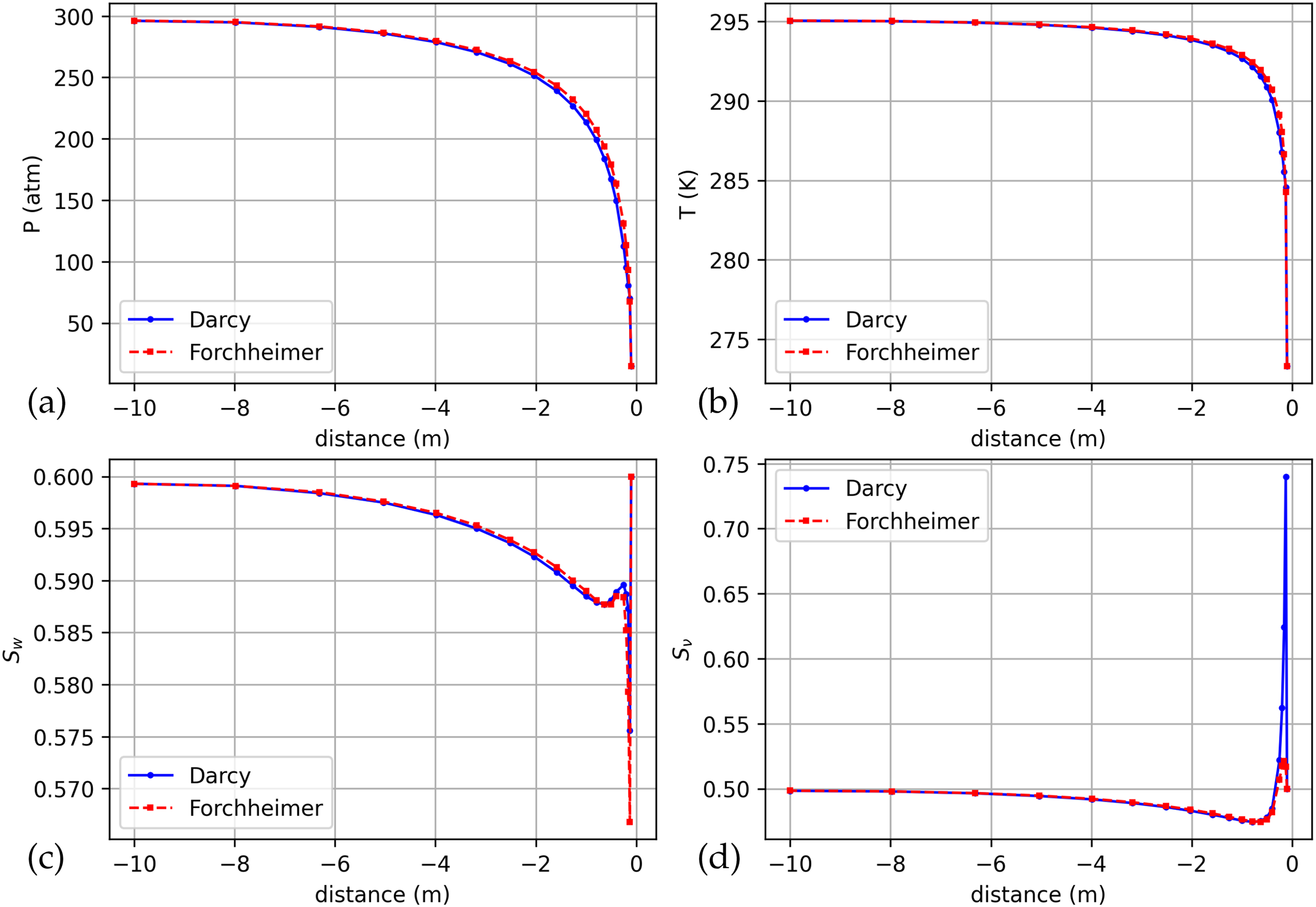
Figure 5: Distributions of pressure (a), temperature (b), water saturation (c) and thawing (d) by radius for the Forchheimer and Darcy models for the time moment
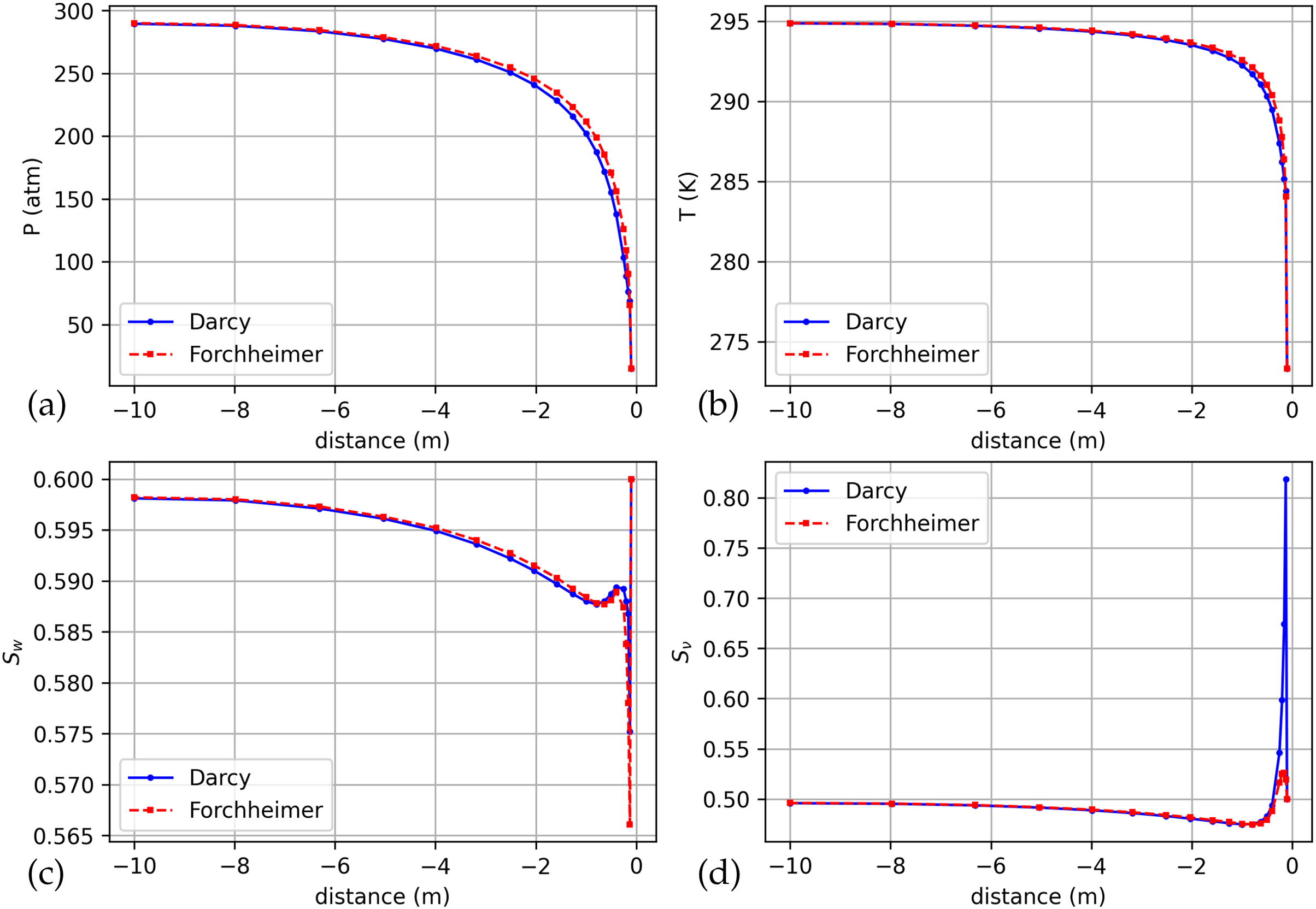
Figure 6: Distributions of pressure (a), temperature (b), water saturation (c) and thawing (d) by radius for the Forchheimer and Darcy models for the time moment
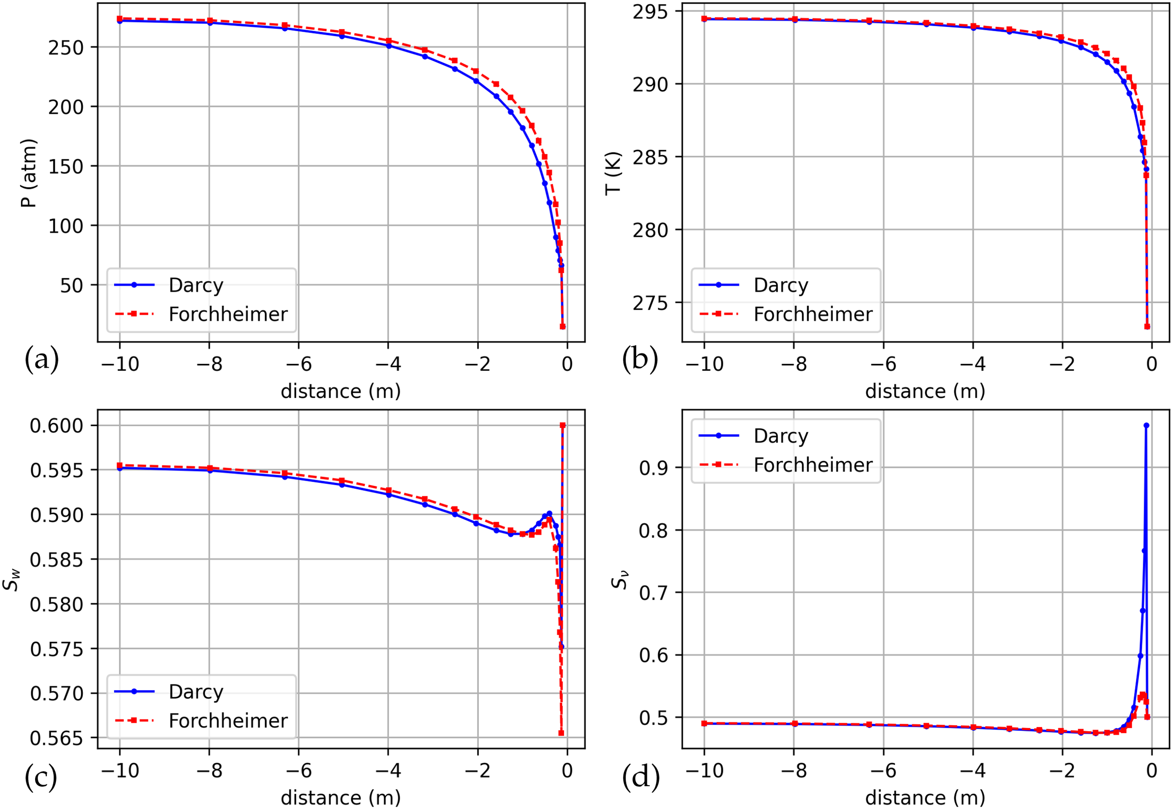
Figure 7: Distributions of pressure (a), temperature (b), water saturation (c) and thawing (d) by radius for the Forchheimer and Darcy models for the time moment
Figs. 5–7 show the distributions of pressure, temperature, water saturation and thawing along the radius for the Forchheimer and Darcy models in dynamics at the moments of time
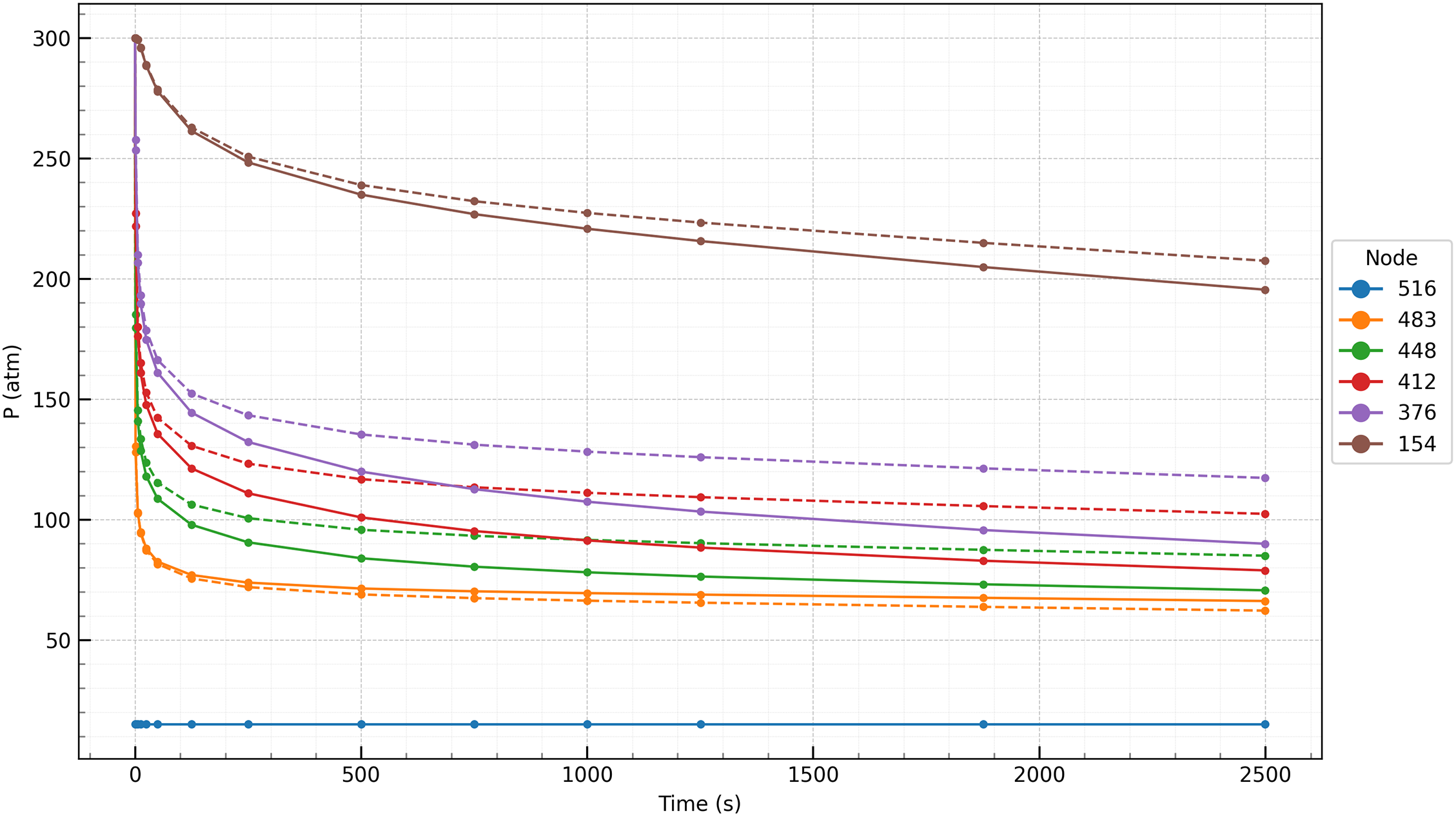
Figure 8: Pressure vs. time at selected nodes (516, 483, 448, 412, 376 and 154) for the Forchheimer (dashed line) and Darcy (solid line) models
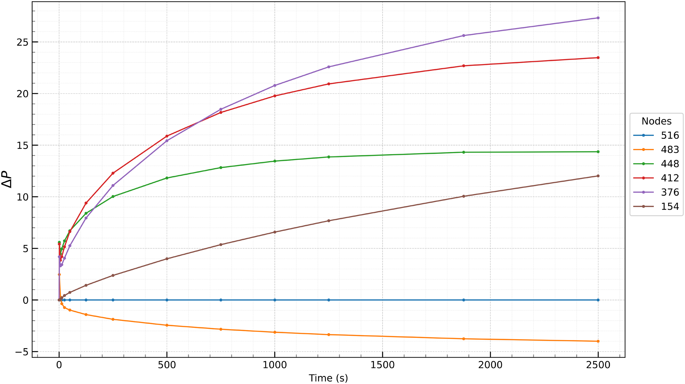
Figure 9: The difference between the pressure dependence on time in the selected nodes (516, 483, 448, 412, 376 and 154) for the Forchheimer and Darcy models
From Figs. 3, 8 and 9, it is clear that the sharp pressure drop near the drain zone is typical for such problems. When filtering according to Forchheimer’s law, the pressure drops more slowly than when filtering according to Darcy’s law, which reflects the influence of inertial effects on the flow dynamics. The greatest difference in pressures in the considered calculation options is observed at the inner boundary, where the flow velocity is the highest, and the difference in pressures there between the Forchheimer and Darcy models initially increases but stabilizes or decreases slightly at later time steps.
Fig. 10 shows the distributions of temperature (Fig. 10a), water saturation (Fig. 10b) and thawing (Fig. 10c) over time for nodes selected in the radial section. The insets in Fig. 10b,c show fragments of the overall picture on an enlarged scale.
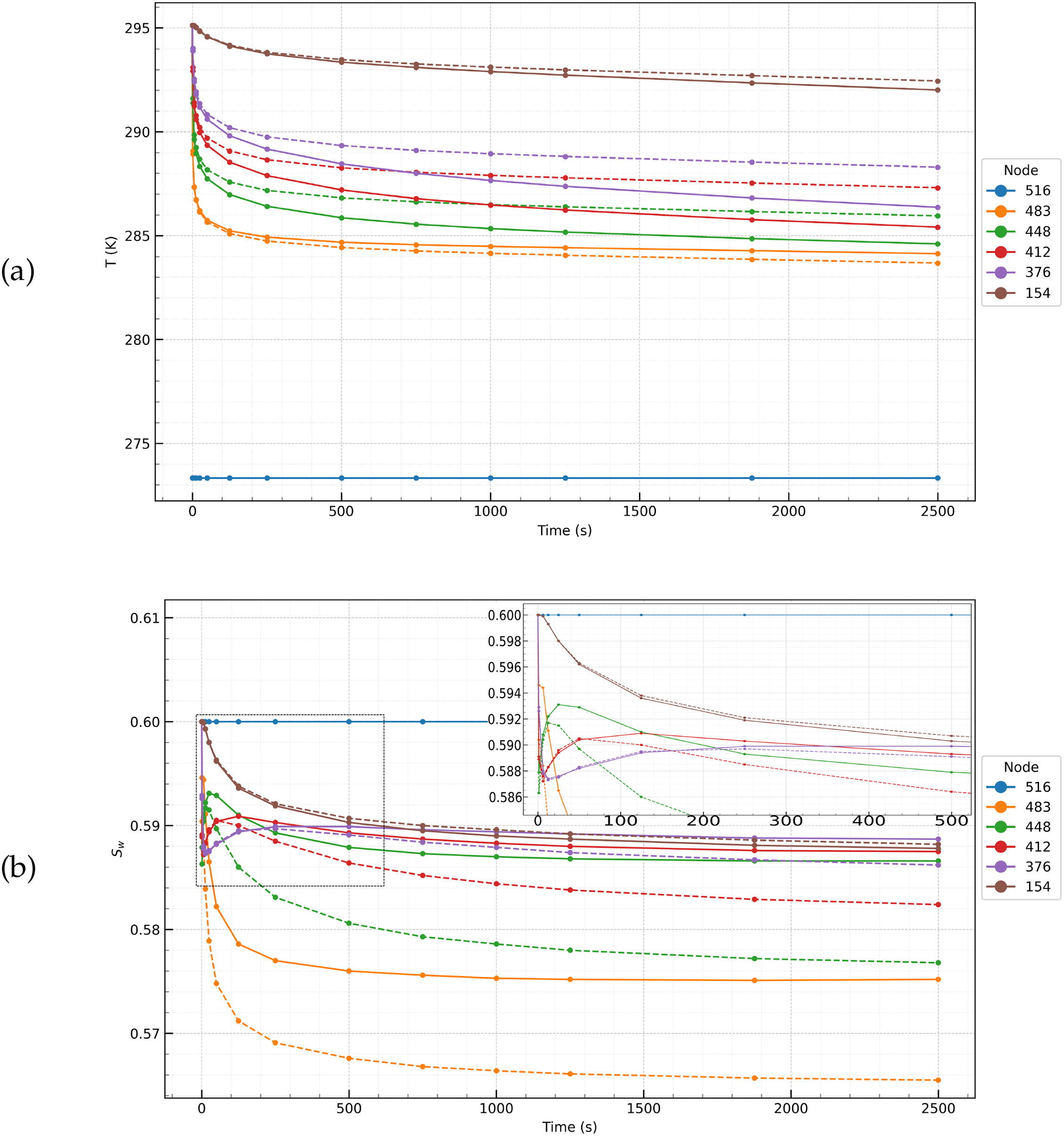
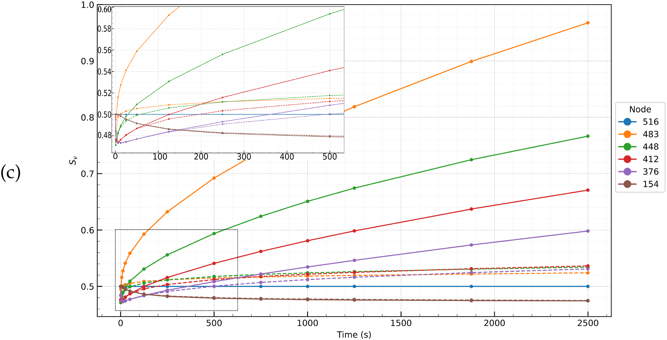
Figure 10: Distributions of temperature T (a), water saturation
From Fig. 10b, it is evident that water saturation (
In general, the calculation results demonstrate the interaction between pressure gradients, water redistribution and hydrate dynamics under different flow conditions. It turned out that under the given conditions, the effect of the nonlinearity of the filtration law on the dynamics of the process is small. However, the resulting difference in pressures in the vicinity of the well of about 20 atm due to the difference in the filtration laws may be significant for the stability of the bottomhole zone and the removal of rock particles from it. Further research is needed to clarify the full picture of the effect of the nonlinearity of the filtration law on processes associated with underground gas hydrates.
The work considered numerical modeling of multiphase multicomponent filtration taking into account gas hydrates in a porous medium. A method was developed for including high-velocity flows characterized by the nonlinear Forchheimer filtration law into a single computational scheme for filtration modeling based on the support operator method. The support operator method allowed combining a large scale related to the entire region and a small scale corresponding to a narrow area of intensive processes in a single calculation. The used method of approximating differential operators allowed transferring their main properties related to mass and energy balances to a discrete model. Calculation algorithms were created that take into account the nonlinearity of the filtration law, which is essential for modeling fast gas flows leading to destruction of a porous medium. The importance of the approach is due to the high velocity of filtration flows during natural gas emissions from the earth’s interior, which necessitates taking into account deviations from Darcy’s law. In the future, it is planned to develop the work both in the inclusion in the general methodology of problems related to taking into account the anisotropy of the filtration properties of the formation in the Forchheimer law, and in the direction of applying already developed methods to solving geological, environmental and technical problems related to gas hydrates in the bowels of the Earth.
Acknowledgement: The work of A. Bakeer was supported by Damanhour University. The work of G. Kazakevich was funded by IO RAS. The work of V. Podryga, Yu. Poveshchenko, P. Rahimly was supported by KIAM RAS.
Funding Statement: The work was carried out within the framework of the state assignment of Keldysh Institute of Applied Mathematics of RAS (Project No. 125020701776-0) and the Ministry of Education and Science of Russia for IO RAS (Project No. FMWE-2024-0018).
Author Contributions: The authors confirm contribution to the paper as follows: software, visualization, writing—original draft preparation: Ahmed Bakeer; conceptualization, data curation: Grigory Kazakevich; supervision, investigation: Viktoriia Podryga; methodology, project administration, validation: Yury Poveshchenko; formal analysis, writing—review and editing: Parvin Rahimly. All authors reviewed the results and approved the final version of the manuscript.
Availability of Data and Materials: The data that support the findings of this study are available from the Corresponding Author, Viktoriia Podryga, upon reasonable request.
Ethics Approval: Not applicable.
Conflicts of Interest: The authors declare no conflicts of interest to report regarding the present study.
References
1. Rahimpour MR, Makarem MA, Meshksar Meditors. Advances in natural gas: formation, processing, and applications. Volume 3: natural gas hydrates. Amsterdam, The Netherlands: Elsevier; 2024. [Google Scholar]
2. Judd A, Hovland M. Seabed fluid flow: the impact on geology, biology and the marine environment. Cambridge, UK: Cambridge University Press; 2007. 475 p. doi:10.1017/CBO9780511535918. [Google Scholar] [CrossRef]
3. Baranov BV, Lobkovsky LI, Dozorova KA, Tsukanov NV. The fault system controlling methane seeps on the shelf of the Laptev Sea. Dokl Earth Sci. 2019;486(1):571–4. doi:10.1134/S1028334X19050209. [Google Scholar] [CrossRef]
4. Ruppel CD, Skarke AD, Miller NC, Kidiwela MW, Kluesner J, Baldwin W. Methane seeps on the US Atlantic margin: an updated inventory and interpretative framework. Mar Geol. 2024;471(1):107287. doi:10.1016/j.margeo.2024.107287. [Google Scholar] [CrossRef]
5. Urgeles R, León R, Pérez LF, García-Crespo J, Bartolomé R, Marín-Moreno H, et al. Dynamics of the gas hydrate system of the Pacific margin of the Antarctic Peninsula. SSRN. 2024. doi:10.2139/ssrn.4948116. [Google Scholar] [CrossRef]
6. El-Naby AAA, Khalil AE, Talaat A, Ismail A. Gas channels and chimneys detection using post-stack seismic attributes, simian field, offshore west Nile Delta. Egypt J Umm Al-Qura Univ Appl Sci. 2024;19(10):1086. doi:10.1007/s43994-024-00204-3. [Google Scholar] [CrossRef]
7. Li X, Guo X, Tian F, Fang X. The effects of controlling gas escape and bottom current activity on the evolution of pockmarks in the northwest of the Xisha uplift, South China Sea. J Mar Sci Eng. 2024;12(9):1505. doi:10.3390/jmse12091505. [Google Scholar] [CrossRef]
8. De Falco G, Conforti A, Di Martino G, Innangi S, Simeone S, Tonielli R, et al. Geohazard features of the western Sardinia. J Maps. 2024;20(1):2347890. doi:10.1080/17445647.2024.2347890. [Google Scholar] [CrossRef]
9. Bogoyavlensky VI, Nikonov RA, Bogoyavlensky IV. New data on intensive Earth degassing in the Arctic in the north of Western Siberia: thermokarst lakes with gas blowout craters and mud volcanoes. Arktika Ekologiya i Ekonomika. 2023;13(3):353–68. (In Russian). doi:10.25283/2223-4594-2023-3-353-368. [Google Scholar] [CrossRef]
10. Chuvilin E, Sokolova N, Davletshina D, Bukhanov B, Stanilovskaya J, Badetz C, et al. Conceptual models of gas accumulation in the shallow permafrost of Northern West Siberia and conditions for explosive gas emissions. Geosciences. 2020;10(5):195. doi:10.3390/geosciences10050195. [Google Scholar] [CrossRef]
11. Schurmeier LR, Brouwer GE, Fagents SA. Formation of the Siberian Yamal gas emission crater via accumulation and explosive release of gas within permafrost. Permafrost Periglac Process. 2023;35(1):33–45. doi:10.1002/ppp.2211. [Google Scholar] [CrossRef]
12. Alekseeva N, Popov S, Poveshchenko Yu, Podryga V, Kazakevich G, Chuvilin E, et al. Implementation of numerical modeling algorithms to examine the filtration of multiphase flow through the gas hydrate stability zone in the Ross Sea. Environ Res Commun. 2025;7(3):035017. doi:10.1088/2515-7620/adb240. [Google Scholar] [CrossRef]
13. Bear J. Dynamics of fluids in porous media. New York, NY, USA: American Elsevier; 1972. [Google Scholar]
14. Govindarajan SK, Pavan TNV, Devarapu SR, Kumar G. Critical review on challenges in the application of Darcy’s law for multi-phase fluid flow in petroleum reservoirs. Discov Appl Sci. 2025;7(3):201. doi:10.1007/s42452-025-06632-y. [Google Scholar] [CrossRef]
15. Forchheimer P. Wasserbewegung durch Boden. Z Ver Deutsch Ing. 1901;45:1782–8. (In German). [Google Scholar]
16. Saboorian-Jooybari H, Pourafshary P. Significance of non-Darcy flow effect in fractured tight reservoirs. J Nat Gas Sci Eng. 2015;24(2):132–43. doi:10.1016/j.jngse.2015.03.003. [Google Scholar] [CrossRef]
17. Elsanoose A, Abobaker E, Khan F, Rahman MA, Aborig A, Butt SD. Estimating of non-Darcy flow coefficient in artificial porous media. Energies. 2022;15(3):1197. doi:10.3390/en15031197. [Google Scholar] [CrossRef]
18. Arbabi S, Sahimi M. The transition from Darcy to nonlinear flow in heterogeneous porous media: i—Single-phase flow. Transp Porous Media. 2024;151(4):795–812. doi:10.1007/s11242-024-02070-3. [Google Scholar] [CrossRef]
19. ŚnieŻek D, Naqvi SB, Matyka M. Inertia onset in disordered porous media flow. Phys Rev E. 2024;110(4):045103. doi:10.1103/PhysRevE.110.045103. [Google Scholar] [PubMed] [CrossRef]
20. Owusu R, Sakyi A, Dontwi IK, Amoako-Yirenkyi P. A new macro-scale volume averaged transport model for diffusive dominated non-Darcian flow problem in multi-scaled naturally fractured reservoirs. J Pet Explor Prod Technol. 2022;12(9):2511–22. doi:10.1007/s13202-022-01498-x. [Google Scholar] [CrossRef]
21. Huang T, Du P, Peng X, Wang P, Zou G. Pressure drop and fractal non-Darcy coefficient model for fluid flow through porous media. J Pet Sci Eng. 2020;184(8):106579. doi:10.1016/j.petrol.2019.106579. [Google Scholar] [CrossRef]
22. Zolotukhin AB, Gayubov AT. Analysis of nonlinear effects in fluid flows through porous media. J Pet Explor Prod Technol. 2022;12(8):2237–55. doi:10.1007/s13202-021-01444-3. [Google Scholar] [CrossRef]
23. Barree RD, Conway MW. Beyond beta factors: a complete model for Darcy, Forchheimer, and trans-Forchheimer flow in porous media. In: Proceedings of the SPE Annual Technical Conference and Exhibition; 2004 Sep 26–29; Houston, TX, USA. doi:10.2118/89325-MS. [Google Scholar] [CrossRef]
24. Evans EV, Evans RD. Influence of an immobile or mobile saturation on non-Darcy compressible flow of real gases in propped fractures. J Petrol Technol. 1988;40(10):1343–51. doi:10.2118/15066-PA. [Google Scholar] [CrossRef]
25. Wu YS. Multiphase fluid flow in porous and fractured reservoirs. Houston, TX, USA: Gulf Professional Publishing; 2016. [Google Scholar]
26. Kh Aziz, Settari E. Petroleum reservoir simulation. London, UK: Applied Science Publishers; 1979. 476 p. [Google Scholar]
27. Rahimly PI, Poveshchenko Yu A, Rahimly OR, Podryga VO, Kazakevich GI, Gasilova IV. The use of splitting with respect to physical processes for modeling the dissociation of gas hydrates. Math Models Comput Simul. 2017;10(1):69–78. doi:10.1134/S2070048218010118. [Google Scholar] [CrossRef]
28. Poveshchenko Yu A, Rahimly PI, Rahimly OR, Podryga VO, Gasilova IV. A numerical approach to study the thermal influence on gas hydrates by physical process splitting. Int J Numer Anal Model. 2020;17(3):404–33. [Google Scholar]
29. Samarsky AA, Koldoba AV, Poveshchenko Yu A, Tishkin VF, Favorsky AP. Difference schemes on irregular grid. Minsk, Russia: JSC “Criterion”; 1996. (In Russian). [Google Scholar]
30. Lipnikov K, Manzini G, Shashkov M. Mimetic finite difference method. J Comput Phys. 2014;257(Part B):1163–222. doi:10.1016/j.jcp.2013.07.031. [Google Scholar] [CrossRef]
31. Bakeer AE, Poveshchenko Yu A, Podryga VO, Rahimly PI. About one spatial filtration model with a nonclassical law of motion in a hydrate-containing environment. Math Models Comput Simul. 2024;16(4):572–85. doi:10.1134/S2070048224700236. [Google Scholar] [CrossRef]
32. Wang X, Economides M. Advanced natural gas engineering. Houston, TX, USA: Gulf Publishing Company; 2009. 417 p. [Google Scholar]
Cite This Article
 Copyright © 2025 The Author(s). Published by Tech Science Press.
This work is licensed under a Creative Commons Attribution 4.0 International License , which permits unrestricted use, distribution, and reproduction in any medium, provided the original work is properly cited.
 Downloads
 Citation Tools