
 Submit a Paper
 Propose a Special lssue
 Open Access
ARTICLE

Numerical and Experimental Study of Thermal Storage Energy in a Building with Various Pipeline Design under Floor—Case Study
Mechanical Department, Engineering College University of Baghdad, Baghdad, 10074, Iraq
* Corresponding Author: Rafah H. Zaidan. Email:
(This article belongs to the Special Issue: Advancements in Heat Transfer Research for Thermal Energy Storage: Emerging Trends and Real-World Applications)
Frontiers in Heat and Mass Transfer 2025, 23(5), 1595-1620. https://doi.org/10.32604/fhmt.2025.068205
Received 23 May 2025; Accepted 14 August 2025; Issue published 31 October 2025
 View Full Text
 Download PDF
Abstract
This paper presents a comprehensive experimental and numerical investigation of radiant floor heating (RFH) systems integrated with phase change material (PCM)-based thermal energy storage (TES). The study compares two underfloor pipe configurations: double serpentine and spiral. It also looks at how well a paraffin wax PCM system works with compact heat exchanger-type TES units during winter in Iraq. Key performance indicators including discharge temperature, heat transfer rate, liquid fraction evolution, and temperature uniformity were assessed through in situ experimental measurements and ANSYS fluent simulations. Results demonstrate that the spiral design provides slightly more uniform temperature distribution on the tile surface at an inlet water temperature of 55°C, with an average difference of approximately 0.5%, the serpentine layout exhibits higher slab temperature distribution by about 0.66%. Notably, the serpentine configuration shows superior thermal homogeneity and heat distribution, with a 15.05% increase in heat gain at a 55°C inlet temperature compared to the spiral design. The performance gap between the two layouts narrows as the inlet temperature increases from 50°C in 5°C increments by approximately 4.1%, 3.7%, and 1.7%, respectively. Higher inlet temperatures also improve PCM discharging and charging rates, improving energy storage utilization. The findings provide significant design guidelines for sustainable heating systems for cold climates.Keywords
With increasing demand for energy-efficient heating systems, radiant floor heating (RFH) has been favored as the most sought-after technology due to its capability for balanced temperature distribution and lower operating costs compared to standard HVAC systems. Radiant floor heating (RFH) has been identified as one of the most important decarbonization technologies in the building sector, thanks in the building to its compatibility with renewable energy systems, long-term performance, and reduced maintenance costs. (Liang et al., 2025 [1]) RFH systems are also identified as increasing thermal comfort and energy efficiency levels, making them worldwide favorites, predominantly for single-family dwellings. Specifically, Baek and Kim [2] have researched PCM radiant floor heating systems under consideration due to their capability to reduce heating energy consumption through improved energy efficiency from existing installed systems.
Through which scholars achieved this (Park and Kim, 2019 [3]) by studying the combination of incorporating a Polymer Matrix into conventional floor structures to improve floor heat storage performance. It found that an innovative PCM-based radiant floor heating system, suitable for wet building construction, was feasible. The optimum melting point of the PCM temperature was 35°C–45°C, and a mock-up test showed the PCM system could maintain a 0.2°C higher temperature. However, the study did not consider factors like sunlight, air movement, and light.
While (Zhao et al., 2017 [4]) studied a simulation modle as the initial phase of establishing the physical and dynamic aspects of a solar phase-change heat storage heating system. where the system includes flat-plate solar collectors, a water tank with a plate for storing heat through phase change, a plate heat exchanger, and auxiliary heat sources. The models account for the entire heating cycle and operation in various modes. Seven distinct operation modes were proposed: free cooling, reservation of heat, direct supply, utilisation of heat stored in the tank, combination of heat stored in the tank and auxiliary sources, and exclusive use of auxiliary heat sources.
Conducted (González and Prieto, 2021 [5]) study a Computational Fluid Dynamics (CFD) analysis on hydronic radiant heating floors that incorporate PCM bands into a concrete core. This analysis took into account different configurations related to bandwidth and positioning in relation to the heating pipes. The heat transmission solutions were contrasted with those derived from radiant flooring devoid of PCM. The examined impacts included the thickness of a wooden cover, regarded as the primary thermal resistance of the flooring, the interior air temperature, and the surface temperature of the heating pipes. The experiment confirms that the radiant floor heating system using PCM strips remarkably improved thermal energy storage and performance. The gradual delivery of heat and longer comfort periods made these flooring systems highly valuable for renewable energy sources integration, winter energy cost reductions, and improving climatic consistency indoors. The investigations up to the current date all target achieving the objective, thus the researcher (Lu et al., 2020 [6]) conducted a 26-day experiment considering using phase change material (PCM) in a floor heating system to minimize the decrease in energy supply and demand mismatches. The system was simulated using four different modes of operations, achieving an average temperature of 18.9°C during the first phase of heating and 2.1°C a daily change of temperature. The findings were that the heating appliance could be operated at half power with a moderate heating load to achieve interior thermal comfort. Intermittent double pipe PCM floor heating resulted in low temperature swings, with an internal variation of 1.8°C and an average of 3°C. The PCM at the output could not fully store heat, and there was also a need for further optimisation.
Research by (Larwa et al., 2021 [7]) at the University of Ferrara, Italy, made an effort to incorporate phase change materials into underfloor heating systems. The work involved experimental tests at the lab scale and also simulated through the creation of a two-dimensional system via COMSOL Multiphysics. The work indicated elevated thermal conductivity of mortars, enhancing the thermal performance of the system. Steady-state operating conditions resulted in an increase of 60% and 100% of heat flow under wet send conditions and transient conditions, respectively. The incorporation of PCM containers underneath heating pipes improved thermal efficiency. The research indicated that higher thermal conductivity and positioning phase change materials underneath heating pipes enhances water temperatures for elevated heat flux conditions. The work validated the thermal efficiency of the PCM-added radiant floor heating system.
Study by Kong et al. [8] made use of an original system of heating referred to as low-temperature radiant flooring integrated with intermittent stratum ventilation (LTR-ISV), with the goals of improving the quality of indoor air and lowering the consumption of energy. Researchers compared the system using conventional radiant floor heating (CRFH) and heating with mixing ventilation (CRFH + MV). The results showed LTR-ISV to process higher operative temperature and higher ventilation flow rate, providing higher exergy efficiency. The system also lowered the usage of electricity was contributed mostly by the primary air handling unit. LTR-ISV was also found to lower pollutants indoors and reduce viral concentration more significantly, with an average concentration of CO2 being lower than CRFH + MV by 400. The risk of transmission by the air was also found to be lower by 5.35 times with exposure time being equal. Beiranvand and Mohaghegh [9] explored the phase change material effect on energy-saving in a significant office building located in Eastern Iran. The energy consumption of the structure in cold seasons was modelled using Design Builder software, and the melting points of three varieties of phase change materials were examined. The simulation results indicated that modifying the arrangement of phase change materials according to their melting temperatures enhanced energy storage. The preliminary scenario focused on the melting temperature and stratification sequence of the walls over many floors, leading to reduced energy requirements. In the second scenario, two distinct combinations of two layers of phase change materials were included in the wall, yielding a 3.8% decrease in energy use.
The study examined three circular fin models for latent heat storage: shell-and-tube, shell-and-nozzle, and shell-and-reducer by Hasan and Hassoon [10]. In which six specimens were examined for two distinct heat transfer fluid (HTF) inlets. The melting completion time was the sole distinction between the models, as the liquid fraction and temperatures were comparable. The melting process was aided by the bottom water inlet, and hot water was brought nearer to the bottom solid paraffin. Melting time for the bottom water inlet was reduced by 11.2% with shell-and-nozzle, and melting time was slowed down by 24% with shell-and-reducer. The thermal performance was optimum and the melting time was reduced to the least with the shell-and-nozzle with bottom HTF inlet. The melting process was expedited with the help of fins, adding enhancement to the surface of heat transmission.
Hussien et al. [11] also discussed the usage of phase change materials, like paraffin wax RT55 and lauric acid, in an integral thermal storage system with a triple pipe heat exchanger. The study found there was an obvious trend displayed by the paraffin-water storage system, as compared to the paraffin-lauric acid system. The temperature differential between PCMs and HTFs improved the interaction between them. PCM1 had a higher melting rate as opposed to PCM2 and reduced the time of heat storage. PCM1 also showed an improved energy efficiency of 47% and an increase of 9.45% in exergy efficiency. The entropy generation number also decreased as the phase change material’s mean temperature improved.
de Gracia and Cabeza [12] reviewed the application of TES for enhancing the thermal comfort and energy efficiency of buildings. Discussed sensible, latent, and thermochemical storage technologies, with particular reference to phase change materials (PCMs) because of the capability of improving passive and active systems of heating and cooling. Stressed the fact that PCMs could be combined with building envelopes, HVAC systems, and seasonal storage systems to enable renewable energy utilization, shifting of peak load, and energy efficiency. The high cost and technical issues pertaining to stability, leakage, and fire hazards were also reviewed as part of the limitations of TES technologies alongside various PCM encapsulation technologies. A comprehensive overview of phase change materials (PCMs) for thermal energy storage (TES) was published by Nazir et al. [13], with emphasis on classification, thermophysical properties, and performance enhancement strategies. The overview considered the applications of organic, inorganic, and eutectic PCMs based on the melting point, storage density for thermal energy, and thermal conductivity. Methods of enhancing PCM performance, such as nanoencapsulation, nanomaterial admixtures, and hybrid TES systems, were also included. Applications of PCMs for concentrated solar power (CSP), thermal management of batteries, building energy storage, and cold storage were reviewed, highlighting them as instruments to fight the intermittency of energy and boost efficacy. As well as explored challenges such as low thermal conductivity, phase segregation, and supercooling, and explored future research directions aimed at cost reduction and commercialization. (Zhang et al., 2016 [14]) developed a solar energy phase change storage floor radiant heating system to enhance interior comfort during the winter months. The system comprises evacuated heat pipe solar collectors, a vertical phase change thermal energy storage device (VPCTESD), and a radiant floor heating system. The system enhanced interior thermal comfort and energy efficiency by 30% relative to conventional systems, even at solar radiation levels above 15 MJ/m2.
Agarwal et al. [15] investigated the mechanisms of convection heating within a test chamber utilising solid-liquid phase change material (PCM) alongside an aluminium PCM carrier. The phase change material was heated in a water bath that was warmed using solar energy. The focus remained on applying water immersion and solar energy to heating systems. Temperature observations were conducted for light winter conditions at various locations in India. The results validated that there was better heating from orientation 1 and better thermal effects from position 2. Phase Change Materials (PCM) store substantial amounts of energy as sensible and latent heat, and offer good thermal comfort.
Rashid et al. [16] investigated using Phase Change Materials (PCMs) in radiant heating and cooling systems to enhance thermal energy storage performance and decrease energy usage. Phase Change Materials (PCMs) may be used to regulate interior temperatures, improving thermal comfort and minimizing HVAC energy usage. The research indicated that using a 10-mm PCM layer decreased heating energy usage by 2.4%, and using a 20–50-mm layer could save up to 15.3%. Researchers found N-eicosane as the ideal phase change material for radiant floor heating. PCM leakage and heat degradation were overcome. While Al-Hinti et al. [17] analysed the practicability of wax-based phase change materials (PCMs) for maximum thermal energy storage of solar water heating systems. In the long term, the PCM-filled aluminium capsules of a hot water storage container gained a temperature advantage of 13°C–14°C, stabilising water temperature variations and minimising heat loss. The study also found that PCM significantly improved temperature restoration following high consumption durations, and this indicates the potential of PCM-enhanced solar water heating to enhance energy efficiency and maximise the utilization of thermal energy.
Sporadic hydronic radiant floor heating systems tend to cause great temperature variations in indoor air due to disturbance [18]. Phase change material (PCM) can reduce this issue by incorporating expanded perlite (EP) into mortar. The 25 mm thick EPPCM-M reduced the temperature variation by 2.5°C and reduced the hot-end cool rates, demonstrating improved heat storage capacity. Simulation work determined the best mixture of EPPCM as follows: 80% Na2HPO4·12H2O, 20% Na2SO4·10H2O, and 2% Na2SiO3·9H2O. The EPPCM-M also demonstrated improved thermal storage performance, and the maximum variation of floor surface temperature was reduced by 55.4% and the maximum variation of maximum and mean temperature of indoor air was reduced by 39.5%.
These examined studies indicate the significance of incorporating phase change material into building thermal storage systems. An effort has been made to address storage system design and operating conditions, as well as the determining character of piping system design for improving the thermal effectiveness of the storage system. The studies demonstrated the significance of designing the pipe layout and storage tank for PCM, a process that incorporated both numerical and experimental analysis. The analysis of thermal performance focused on determining the ability to maintain indoor air and floor surface temperatures at a specified set point within the comfort range. The objective of this study is to investigate thermal energy storage through both numerical and experimental methods in two distinct configurations: spiral and double serpentine pipes installed underfloor. Furthermore, this work introduces a novel design for thermal energy storage utilizing a model of compact heat exchanger-type circular tubes equipped with rectangular fins. The study utilized ANSYS-Fluent 21 software for numerical simulations.
2 Numerical Simulation of TES and Rooms
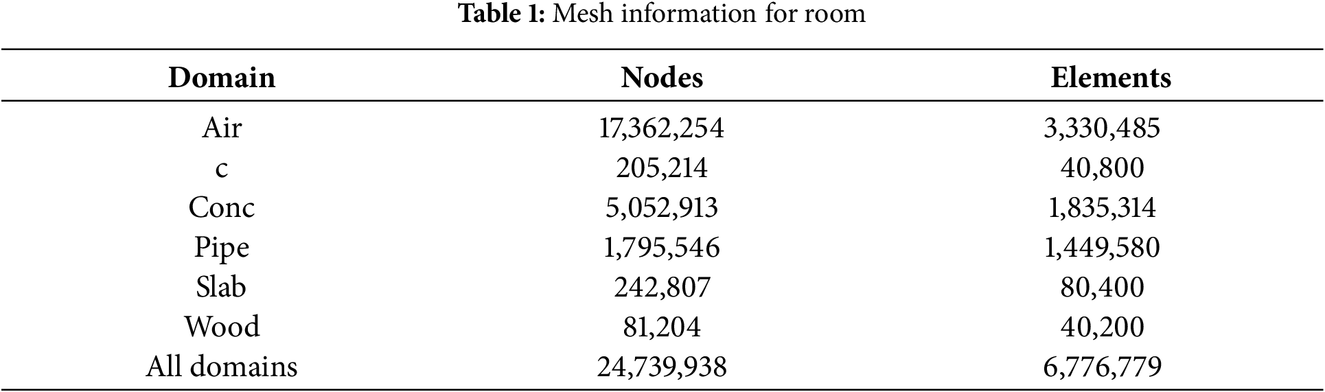
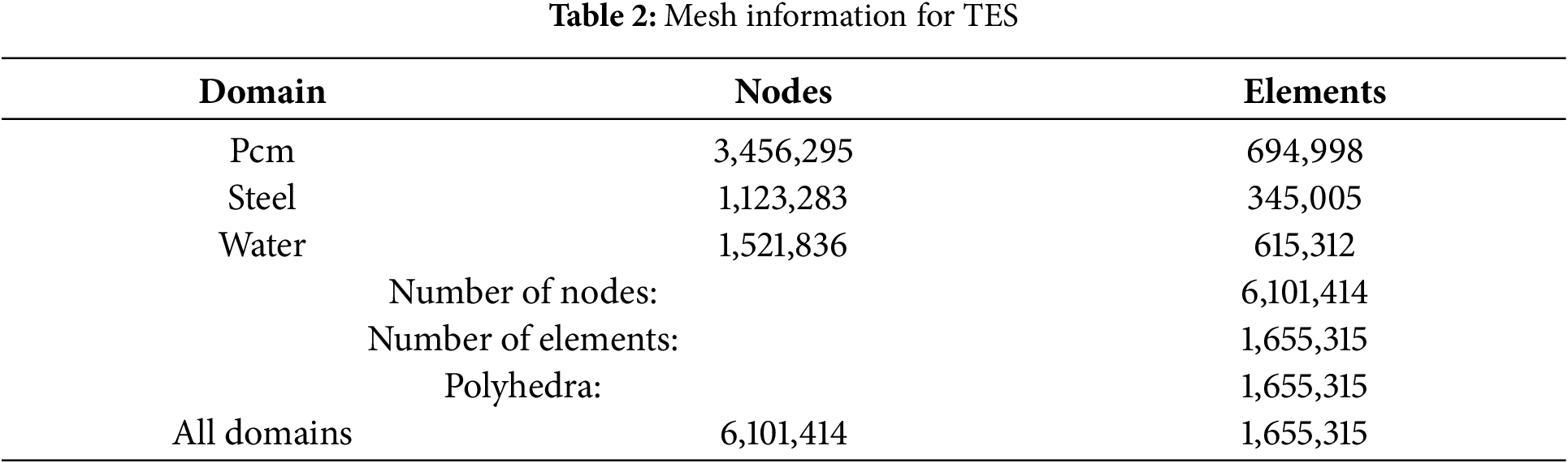
TES and rooms have been successfully created using the ANSYS FLUENT 2021R1 Software Package to study temperature changes, charging and discharging processes, as well as flow and energy in the rooms. The software built the precise scale of TES and full rooms. The simulation of TES was divided into two domains: water passages and PCM, as the material was input. The simulation of rooms concentrated on the design configurations while studying two layouts (spiral and serpentine) to ensure temperature comfort. The software offers the capacity to model objects, mesh them, apply appropriate boundary conditions, and simulate them under real-world conditions to achieve desired outcomes. The current study employs three-dimensional models to simulate the scenarios. These models undergo four stages: geometry construction, meshing, post-processing, and results analysis. Ansys Fluent simultaneously resolved the continuity, momentum (X, Y, Z), and energy equations. Fig. 1 illustrates the convergence for TES, while Fig. 2 focuses on rooms. While the information on the ANSYS program is shown in Tables 1 and 2.
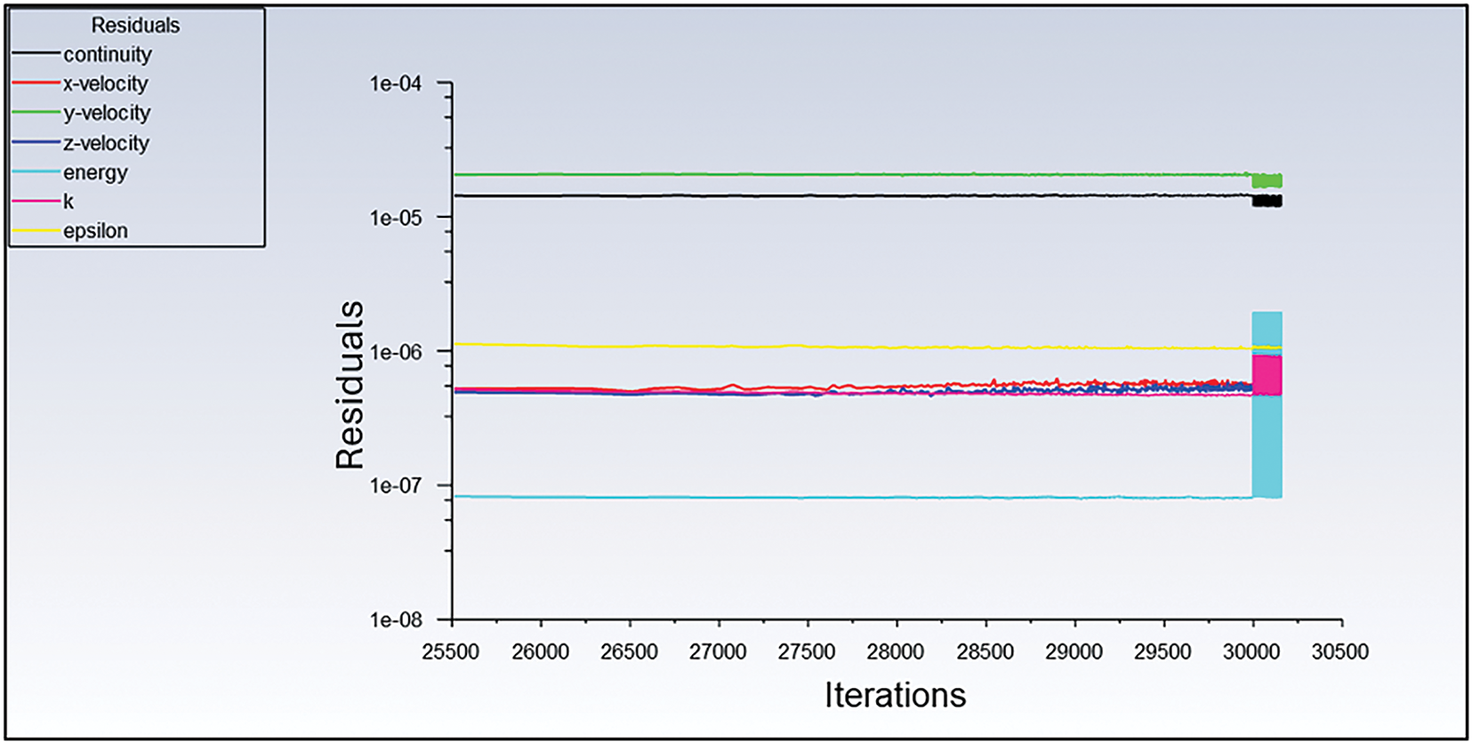
Figure 1: Residual Solution for thermal energy storage (TES)
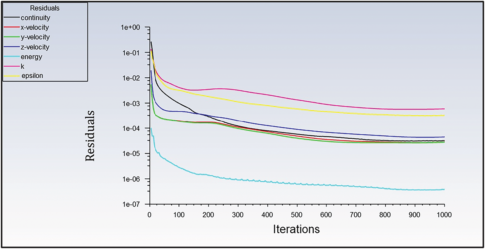
Figure 2: Residual solution for room
It is essential to conduct a mesh independence analysis in Computational Fluid Dynamics (CFD) to ensure that the results are solely influenced by the boundary conditions and physics utilized, rather than the mesh resolution. The systematic increase in resolution and the execution of repeated simulations are two methods that are frequently employed to evaluate grid independence. It is probable that the initial grid is adequate if the results do not undergo a substantial change. Four specific grid sizes have been subjected to calculations. The results of the models were exported to Fluent for the purpose of setting up and conducting analyses. Once an arrangement that was satisfactory was attained. Refer to Fig. 3 illustrates the mesh generation for the room, while Fig. 4 illustrates the mesh generation for the Thermal Energy Storage.
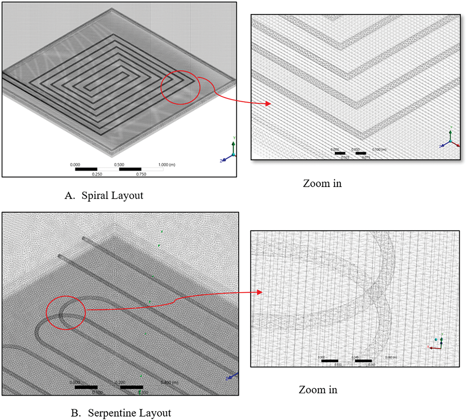
Figure 3: The mesh generation for rooms with two layouts. (a) shows the mesh of the spiral layout in the first room, (b) shows the mesh of the second layout in the second room
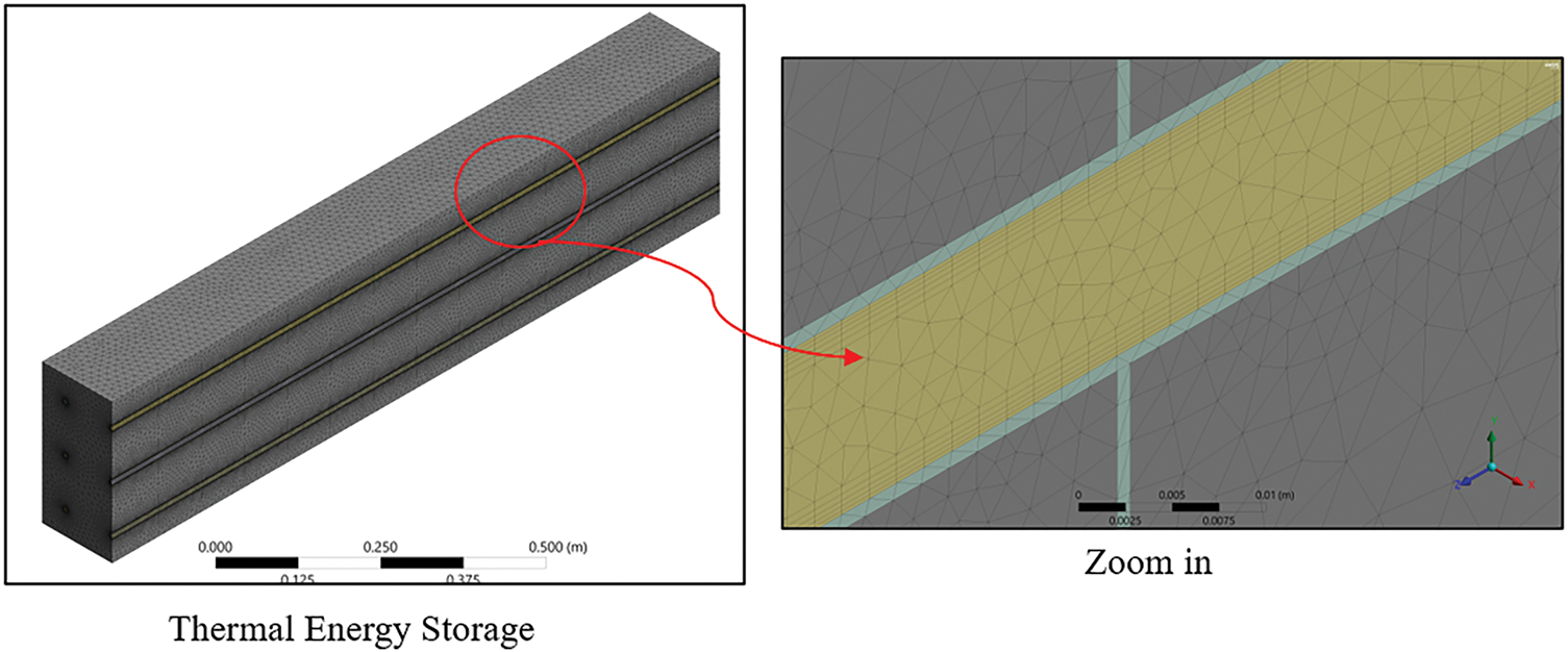
Figure 4: The mesh generation for thermal energy storage (TES)
The current work is divided into two parts: The first part designed two layouts distributed for pipes under the floor for two model rooms while for second part its connected with first partused for saving energy by thermal energy storage model of compact heat exchanger-type circular tubes equipped with rectangular fins illustrated in Fig. 5. But regarding the design of the pipes, it showed Fig. 6, a schematic diagram for spiral layout, double serpentine layout, respectively. Underfloor heating systems with integrated pipes extend over the area of the two rooms, with the piping network configuration varying in each room, taking into account the heat load requirements of each space. The two designs are studied with different inlet temperatures, hot water starting from 50°C and ending at 60°C with a step of 5 degrees, as well as the used a flow rate of the working fluid 9 L/min. In the winter season of Iraq, taking only January month as a case study. The dimensions of each room are (2 × 2 × 2.75) m. length × width × height, respectively.
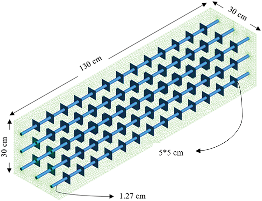
Figure 5: Sketch of thermal energy storage (TES)
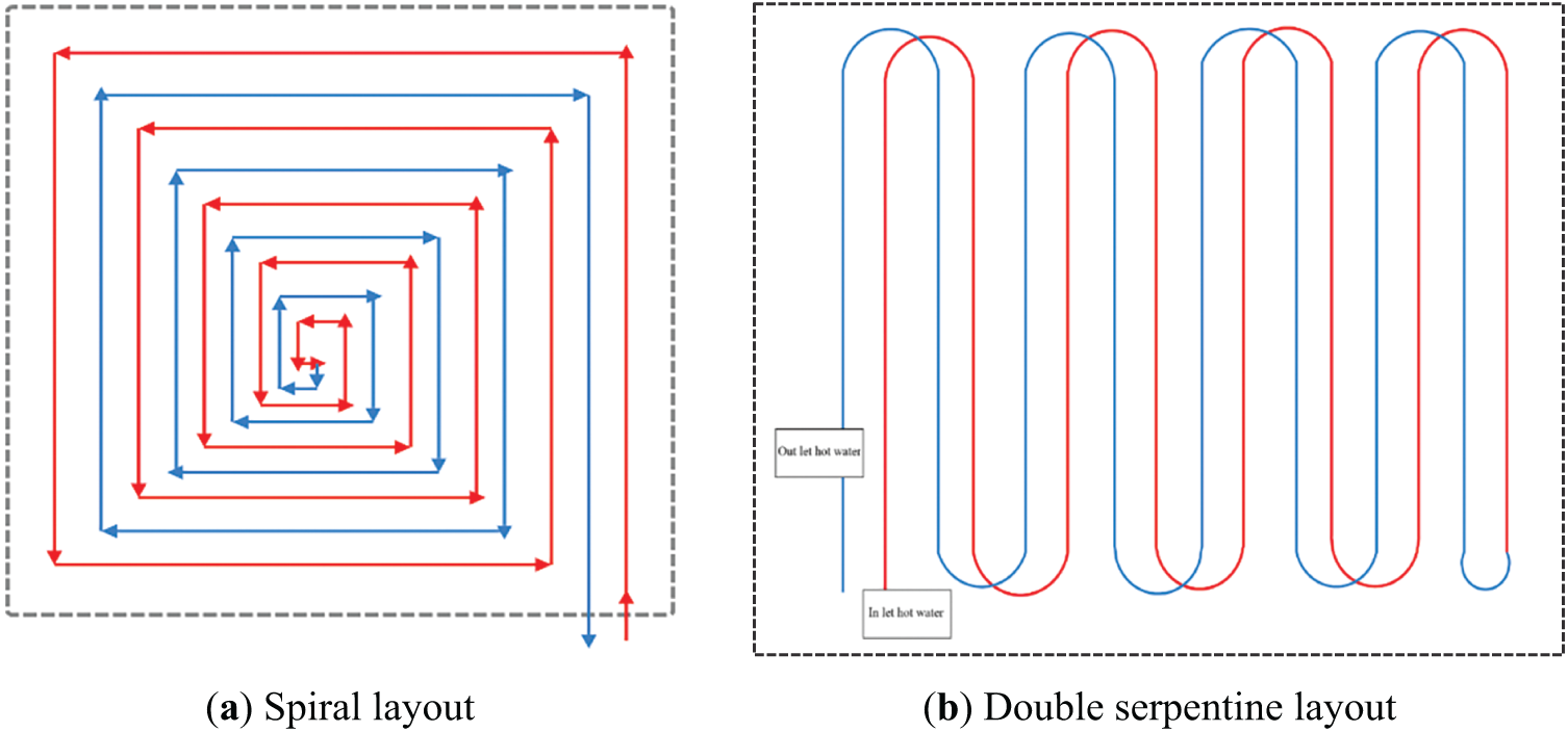
Figure 6: Schematic for pipes layout. (a) Spiral layout; (b) Double serpentine layout
The floor system consists of five layers: ceramic tiles, a cement layer, a pipe network, an insulation layer, and concrete tiles. Use a PEX pipe, which is the most common material for this type of application because it transfers heat well. This system works at outlet temperatures around 60°C. According to the French standard NF DTU 65.14 P1, the concrete floor is good for storing heat and then transferring heat into the rooms. (Anigrou and Zouini, 2024 [19]).
2.3 Assumptions & Governing Equations of Pipe Layouts
The thermal characteristics of the technique panel are:
• Isotropic and temperature independent.
• Temperature slopes of the solid section at the locations where pipelines are fixed are also measured in the analysis.
• Water as a working fluid.
• Built on the studied water speeds inside pipes, the flow is turbulent.
Considering the earlier assumptions, the heat transfer equations for this structure in a 3D configuration and under steady-state conditions are represented by the continuity equation. The equation of conservation energy is split using the 1st-order upwind scheme, while the conservation of momentum equation is discretized using the second-order upwind scheme.
The continuity equation can be illustrated by (Hasan and Hassoon, 2023 [10]):
where v, ρ, and t are the velocity, local density, and time, respectively.
The energy equation is provided in Eq. (2) (Oubenmoh et al., 2018 [20]):
wherever P: static pressure, (τij)eff: stress tensor, Sh is the expressed supplier term provided by equation:
E is the overall energy symbolized by:
The stress tensor (τij)eff is presented by the subsequent relationship, giving:
where I: unit tensor, μ: molecular viscosity, and the next term on the right-hand side is the cause of volume increase.
Differential balance explaining momentum conservation for a Newtonian flow is:
To resolve a governing equation mathematically, the turbulence enclosure model applied here is the model K-ε to analyze the turbulent properties of flow. This kind is presented by Launder and Spalding (‘K-epsilon models—CFD-Wiki, the free CFD reference’ [21]) and provides a general explanation of turbulence using 2 transport relations. The equation for “turbulence kinetic energy”, K, is represented as follows (7) (Ahsan, 2014 [22]):
Equation of the specific dissipation rate of turbulent energy ε is represented by Eq. (8):
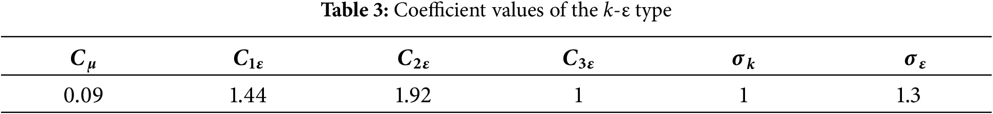
“Gk, Gb, Ym in Eq. (7), the generation of turbulence kinetic energy due to mean velocity gradients, buoyancy, and fluctuating dilatation in compressible turbulence contributes to the overall dissipation rate. Additionally, G1ε, G2ε, and G3ε are constants. The coefficients σk and σε are the turbulent Prandtl numbers for k and ε, respectively. Sk and Sε are user-defined source terms”. The model constants are provided in Table 3.
The ground’s cover temperature average is determined using Eq. (9):
The heat transfer coefficient hw for the surface between water and pipe was calculated from
where L is the characteristic length (m) of the pipe, λp is thermal conductivity of the pipe (W/m·K), di is inner diameter of the pipe (m), Re is Reynolds number (-), Pr is Prandtl number (-).
The heat added or lost was calculated by the equation:
2.4 Governing Equation and Heat Transfer inside PCM
To simplify the complexity of the calculation, we made the following assumptions (Jasim and Jassim, 2023 [23]):
1. Unsteady state and 3D.
2. The thermal energy store is considered in the energy equation.
3. PCM thermo-physical properties are constant within the working.
4. No effect of body forces.
5. Liquid initially at Ti > Tm > To.
6. No slip condition between fluid and boundary.
7. Heat transfer fluid is Newtonian.
8. Boundary conditions (adiabatic wall room, pressure of water inlet pipe to the atmosphere, floor from down is insulated, set temperature room 23°C).
Continuity Equation
The continuity equation can be illustrated by:
Momentum Equation
The momentum source term is:
where:
During PCM’s solidification, the mushy zone constant Amushy serves as a damping factor for the velocity. In literature, its value usually ranges from 104 to 107, but Soibam [24] runs a simulation spanning several values and discovers that 105 produced the best outcomes.
The liquid phase β is written as:
The enthalpy and temperature of PCM are related in the following way:
Energy Equation
The Energy equation can be written as:
Tests were conducted in two test rooms located in Baghdad (33.32° N, 44.23° E), situated above a third-floor residence. Each test room has external dimensions of 2 m (length) × 2 m (width) × 2.75 m (height), with a west-facing aspect and exposure to sunlight throughout the entire season, as there are no nearby shades. The test rooms were constructed using sandwich panels that are 50 mm thick and made of polyurethane foam, which has a thermal conductivity coefficient of λ = 0.0367 W/m·K. The floor consists of five layers: the first layer is wood, 10 mm thick with a thermal conductivity of 0.13 W/m·K; the second layer is a 10 cm thick concrete layer with a thermal conductivity of 1.75 W/m·K, and the third layer is a 5 cm thick cork layer for insulation, with a thermal conductivity of 0.04 W/m·K. This layer is embedded in a PEX-Al pipe tube with an outer diameter of 16 mm and a wall thickness of 1.65 mm, thermal conductivity 0.41 W/m·K, fourth layer from concrete and the last from ceramic tile with a thickness of 1 cm and thermal conductivity 0.8 W/m·K as shown in Fig. 7.
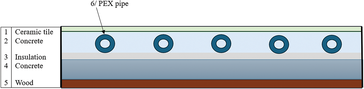
Figure 7: Floor room layers
Where PEX pipes with 16 mm outer diameter were installed in two shapes for two rooms (double serpentine & spiral), see Figs. 8 and 9 for slab heating by water circulation and they are completely embedded in the mortar medium to minimize peripheral heat flux loss and to avoid thermal influence between test specimens. The dimensions of the tile are (60 cm × 60 cm × 1 cm) in total, consisting of 9.5 pieces of ceramic 10 mm thick for each room.
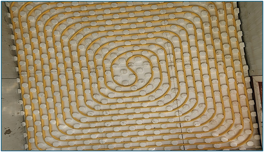
Figure 8: Spiral layout inside room

Figure 9: Double-serpentine layout inside the room
The selection of PCM is essential in the PCM floor heating system. PCMs that are desired require the following characteristics: an appropriate temperature during phase transition, adequate latent heat, chemical stability, and a reasonable price. Which should maintain the inlet hot water temperature at approximately 40°C at least to keep a surface temperature of the floor heating system that typically falls within the range of 19°C to 29°C to reach the comfort conditions (Olesen, 2002 [25]). The system consists of the external shell as a rectangular shape with dimensions (30 cm × 30 cm × 130 cm) made from galvanized plate with pipes arranged as a matrix horizontally & have 9 pipes distributed uniformly (Inner diameter 1.27 cm) and then uses a rectangular fin made from copper to increase heat transfer with dimensions (5 cm × 5 cm × 0.01 cm) and fixes it on pipes.
On the side of the shell, a glass window (10 cm × 15 cm, double glazing with 6 mm thickness and a 4 mm air gap) is installed to observe the melting of the PCM, and the entire TES is covered with rock wool (see Fig. 10). Then fill the shell with PCM selection with the best criteria and fill it with 100 kg of PCM. Table 4 shows the properties of the paraffin used. The schematic design of the system connection used in the current study is shown in Fig. 11. The procedure starts with the boiler, which elevates the water temperature. The heated water is next sent via pipes to the Thermal Energy Storage (TES) system to charge the Phase Change Material (PCM), after which the fluid is transported via pipes to two rooms to heat the floors, aided by a pump that circulates the water throughout the pipes throughout this process. During PCM charging at daytime, then after that, initiate the discharge process at night, allowing hot water to be released from the TES to the radiant heating floor.
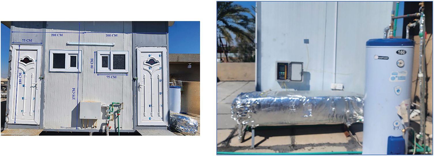
Figure 10: Two test room front and side view with thermal storage tank
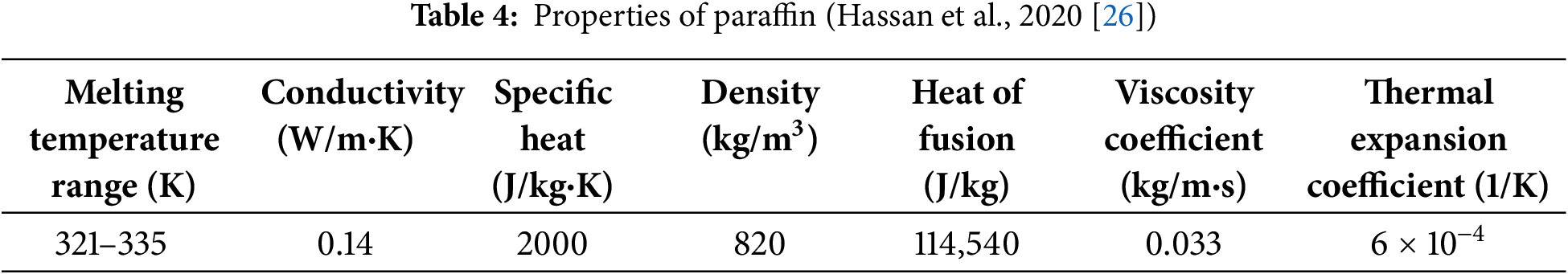
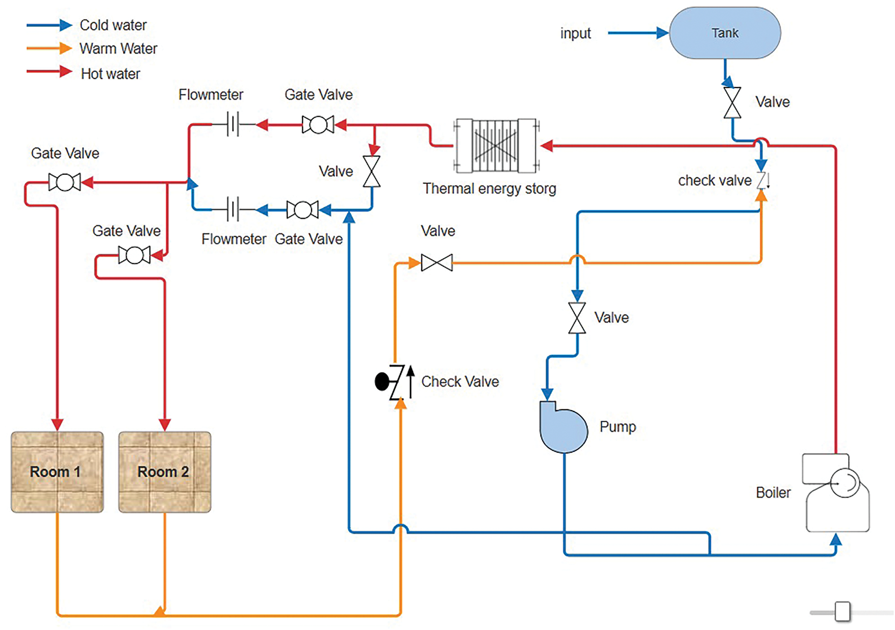
Figure 11: Schematic diagram for the system
A. Without using phase change materials.
Tests 1, 2, and 3 involved heating two test rooms using radiant floor heating supplied with hot water at a flow rate of 9 L/min, heated by an electric boiler. Each test was conducted on a different day and repeated with varying inlet hot water temperatures of 50°C, 55°C, and 60°C. During the heating period, the boiler and circulation pump were continuously operated to supply hot water.
B. With using phase change materials.
Tests 4, 5, and 6 involved charging the PCM using different hot water inlet temperatures by turning on the boiler while closing the valve supplying the rooms. These tests were conducted daily throughout the study period. The boiler was operated for approximately 3 h to reach the desired temperature before starting the circulation pump to circulate water through the PCM.
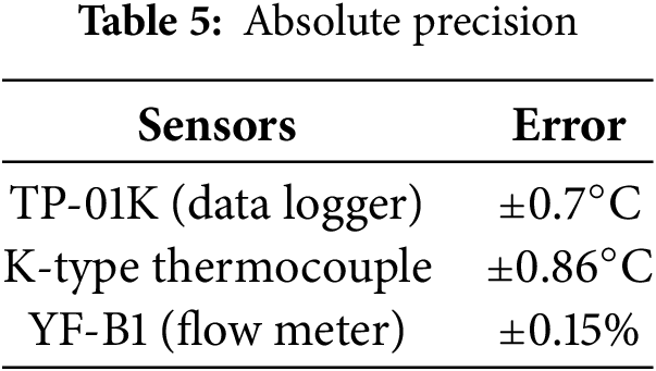
The accuracy of all of the sensors utilised in the experiments is verified. Table 3 showcases the absolute and relative accuracy measurements that were extracted from the data sheets of the devices. Mistakes in the measured quantities are, without a doubt, the largest category of arithmetic errors. Therefore, the Kline and McClintock methodology (Moffat, 1988 [27]) is used to assess the accuracy of the acquired data.
Let the end outcome R rely on a set of variables (v1, v2, …, vn).
This connection may be expressed as a linear equation when the variations in the variables are minimal:
The resulting interval of uncertainty (w) can be expressed as
Dimensionality reduction by division by R:
Consequently, Table 5 provides a comprehensive account of the potential experimental errors that may arise as a consequence of the variables’ implementation.
Under isothermal conditions at 50°C, 55°C, and 60°C, Fig. 12 illustrates the temporal evolution of the liquid fraction (L.F) of the phase change material (PCM) numerically. The melting process is substantially accelerated by higher operating temperatures, as a clear temperature dependency is evident. The PCM achieves a nearly complete liquid fraction (L.F ≈ 1.0) in approximately 8400 s at 60°C, whereas it only reaches this state after 13,560 s at 55°C. Conversely, the liquid fraction stabilizes at approximately 0.6, indicating that the sample does not completely dissolve within the observed timeframe of 18,000 s when exposed to 50°C.
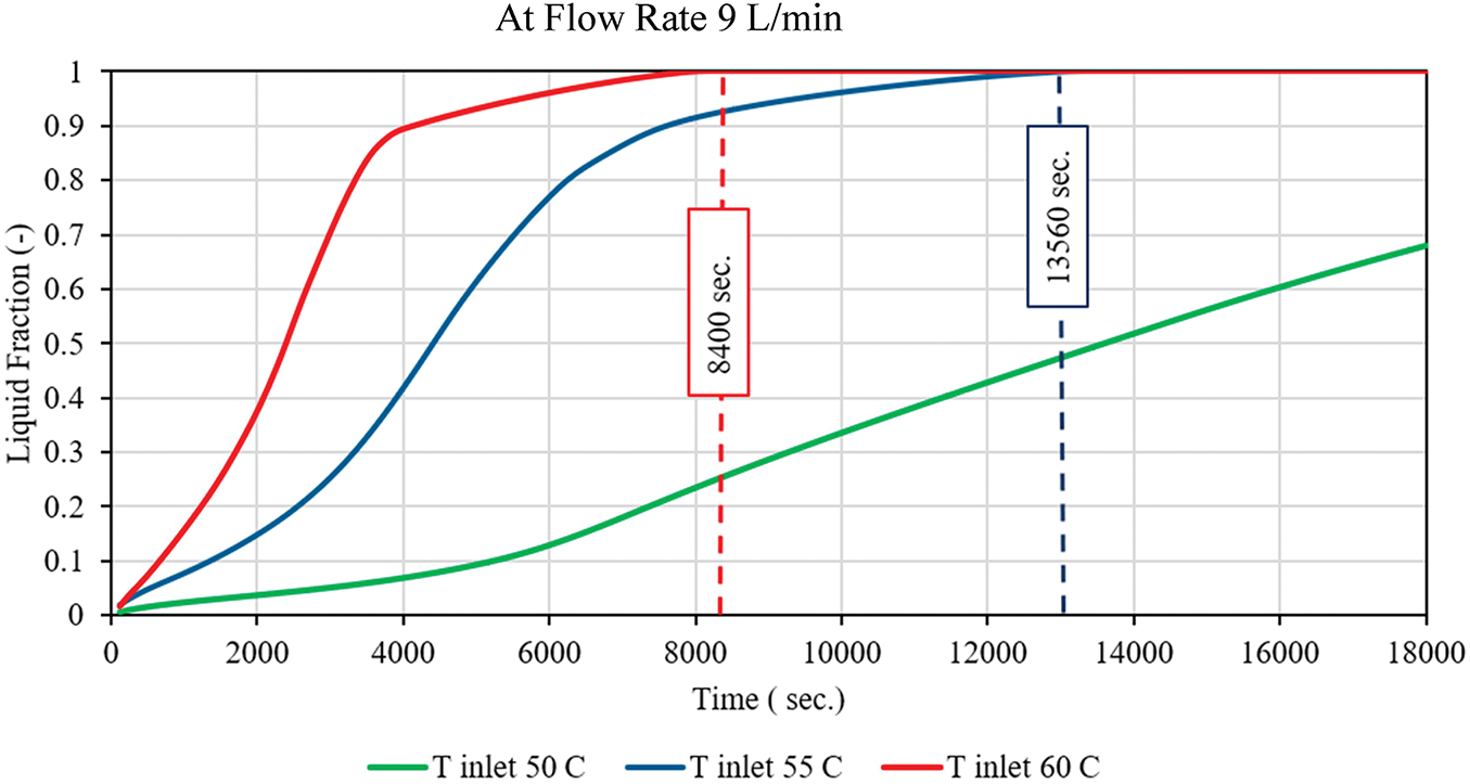
Figure 12: Liquid Friction at 9 L/min with different temp
This trend is consistent with the theoretical predictions of Fourier’s law, which states that the rate of heat transfer increases as the temperature gradient increases, resulting in a quicker accumulation of energy and the absorption of latent heat. The L.F.-time profiles at 55°C and 60°C exhibit a sigmoidal shape, which suggests that an initial induction phase is followed by a rapid melting stage and a final asymptotic approach to saturation. The design and operation of thermal energy storage systems that utilize PCMs are significantly affected by these findings.
For a simulation period of 18,000 s, Fig. 13 illustrates the temporal evolution of outlet temperature for three distinct inlet temperatures: 50°C, 55°C, and 60°C. The simulations were performed in a transient thermal flow configuration using ANSYS Fluent 2021 R1. The fluid and pipe wall domains were assigned temperature-dependent thermophysical properties, and the inlet velocity and pressure outlet boundary conditions were constant.
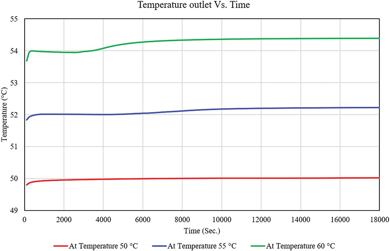
Figure 13: Temperature outlet vs. time at flow rate 9 L/min
The thermal response trend in all cases is consistent, as evidenced by the graph: an initial rapid increase in outlet temperature, followed by a gradual stabilization phase. This behavior is indicative of the thermal inertia of the system, which determines the time necessary to achieve steady-state conditions.
The thermal resistance of the system components and the time lag associated with heat accumulation and transmission along the fluid path are the causes of the initial transient phase. The discharge temperature experiences a rapid increase and subsequently stabilizes at 50.1°C when the inlet temperature is 50°C. The inlet temperature of 55°C results in an increase in the outflow temperature, which ultimately stabilizes at 52.5°C. The inlet case with a temperature of 60°C reaches the maximum outlet temperature, which is approximately 54.2°C at steady state.
The results suggest that an increase in the inlet temperature results in a commensurate increase in the outlet temperature. Nevertheless, the aggregate variation in outlet temperature among the three scenarios is relatively minor (an estimated 2°C difference between each). This consistent monitoring suggests that the system is both thermally responsive and well-insulated, as it indicates efficient heat transfer and minimal losses. The thermal stabilization time, which was estimated to be between 6000 and 8000 s, is consistent with the results of comparable studies on radiant floor heating and PCM-enhanced systems. In these studies, sluggish thermal diffusion and latent heat effects contribute to a delayed but sustained release of heat. This thermal behavior illustrates that higher inlet temperatures enhance thermal performance from a design perspective. However, to obtain more substantial increases in outlet temperature, it may be necessary to optimize heat exchanger geometry or improve convective flow.
Fig. 14 illustrates the simulation of the evolution of PCM temperature under three constant boundary temperatures: 50°C, 55°C, and 60°C. The initial uniform temperature of the PCM is 40°C, and the temperature increases in response to the thermal boundary conditions applied over time. The temperature rise is most rapid in the curve associated with a 60°C boundary condition, with the 55°C and 50°C cases following closely behind. The final steady-state temperatures at 60°C, 55°C, and 50°C are 59.9°C, 54.8°C, and 48°C, respectively. The magnitude of the applied thermal input is clearly connected to the thermal charging rate and the maximum temperature. Each curve exhibits a nonlinear increase, starting with a rapid temperature increase and subsequently transitioning to a gradual plateau or flattening. This plateau is a critical aspect of phase change behavior and is more pronounced in the 60°C and 55°C scenarios. The phase change region commences earlier and concludes more swiftly at elevated temperatures. The simulation verifies that the thermal charging rate and overall energy absorption efficiency are enhanced by increasing the boundary temperature. The findings indicate that the utilization of boundary temperatures of 55°C or higher can substantially reduce charging time while maximizing the energy storage potential of thermal energy storage systems, particularly those operating in conjunction with solar or waste heat sources.
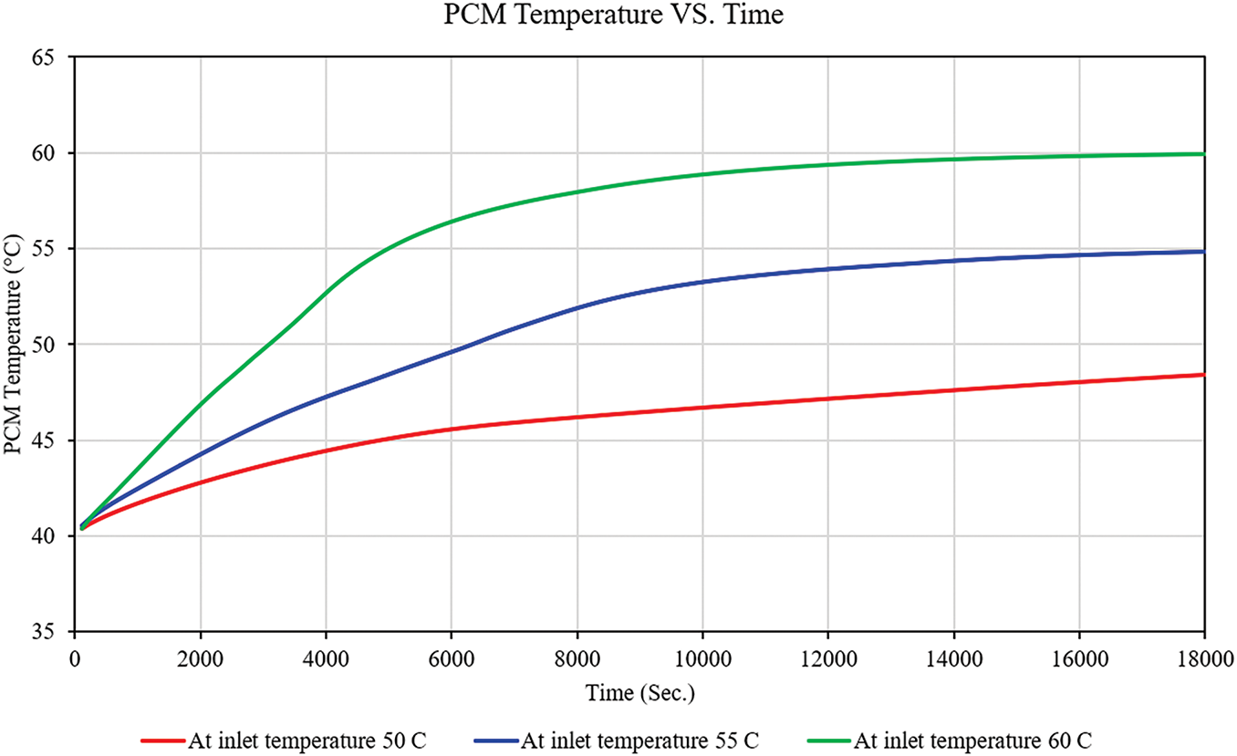
Figure 14: PCM temperature vs. time at 9 L/min flow rate for different inlet temperatures
Fig. 15 shows the Phase Change Material (PCM) temperature distribution numerically during a 24-h discharge cycle after system closure is compared between two pipe configurations: spiral and serpentine. The results show that average room temperatures increase progressively from midnight, reaching their highest point between 12:00 and 14:00, and then decrease as evening approaches. This pattern indicates the PCM’s delayed thermal release behavior, which persists even after the active heating system is deactivated. The serpentine configuration consistently maintained higher room temperatures than the spiral layout throughout the entire discharge period, with a maximum temperature of approximately 27°C during peak hours. The ambient temperature remained substantially lower, fluctuating between 5°C and 18°C. The serpentine configuration’s superior performance is attributed to increased surface area contact and consistent thermal flux along the piping network. The performance disparity becomes more apparent after the midpoint of the day, when both configurations begin to exhibit declining room temperatures, suggesting that the PCM has nearly completed its discharge. The serpentine configuration’s superior thermal storage efficiency is further bolstered by its delayed rate of temperature decline. This data supports the notion that the integration of PCM with radiant floor systems enhances internal thermal comfort during shutdown periods. That’s led to the serpentine layout delivering marginally better heat distribution and cumulative thermal retention during PCM discharge. However, the spiral layout, while slightly less efficient midday, demonstrates comparable overall retention and even slightly stronger performance in the evening decline period.
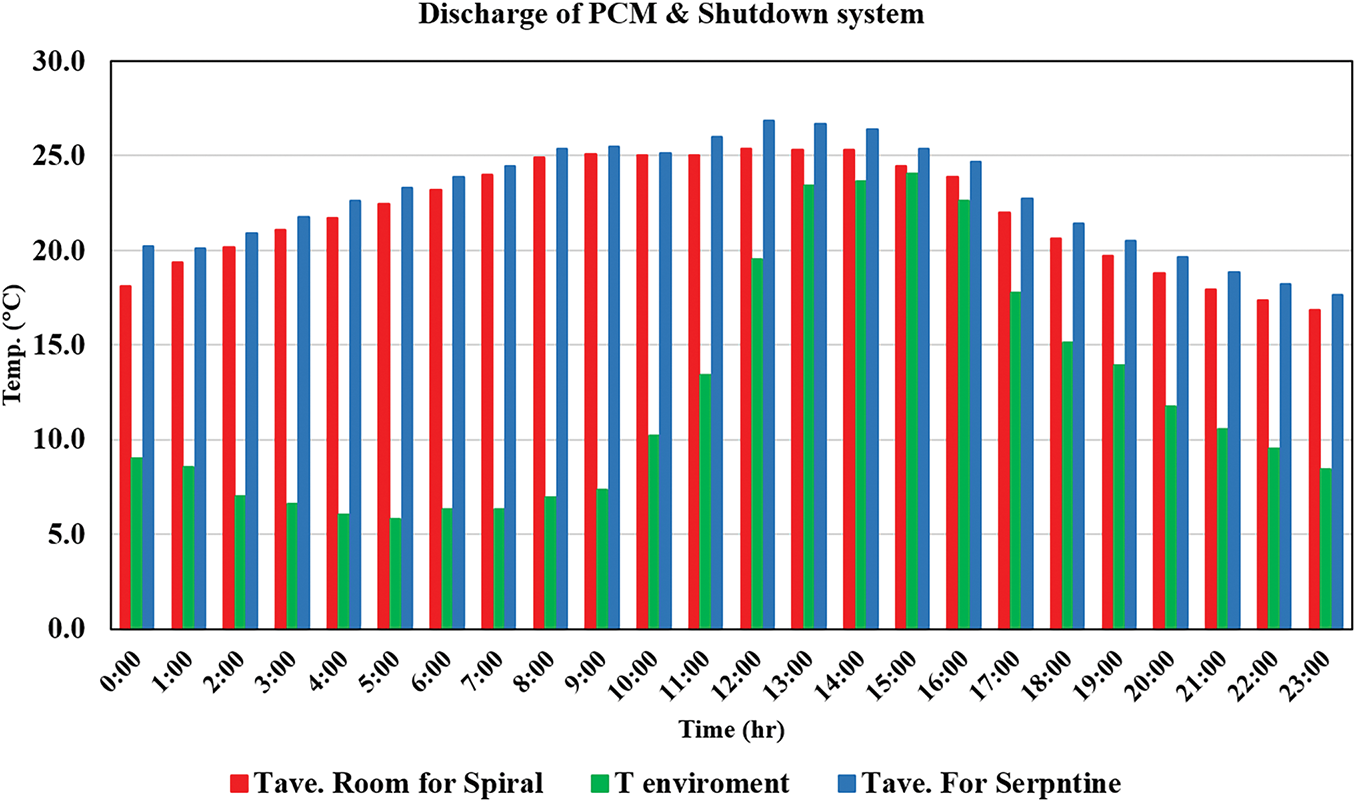
Figure 15: Comparison of PCM discharge temperature vs. time experimentally at a flow rate of 9 L/min
Fig. 16 shows the experimental variation of total heat transfer (Q) over an 8-h period during the passive discharge phase of the phase change material (PCM) system. The serpentine layout exhibits a higher heat release (~125 W) at the start of the discharge process, indicating a more immediate release of stored energy. This may be attributed to the serpentine layout’s larger surface area, enhancing the initial thermal gradient and heat transfer. As time progresses, the heat transfer rate for both layouts steadily increases, reflecting the gradual release of latent heat stored in the PCM. By the third hour, both systems show converging trends with values around 150–160 W. From hour 4 to hour 8, the difference narrows further. At 8:00 h, both layouts reach nearly equal heat transfer rates, indicating most of the PCM’s stored energy has been discharged and approaching thermal equilibrium with the surrounding environment. The serpentine layout consistently delivers slightly higher Q values than the spiral throughout the discharge period.
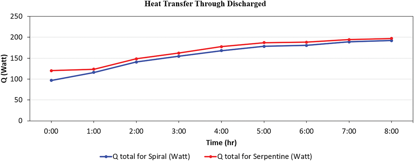
Figure 16: Heat transfer through the room at a flow rate of 9 L/min
Fig. 17 shows the measured heat transfer rate (Q) from the hot water supplied by the PCM to the room over time during the discharge phase of the PCM system, comparing spiral and serpentine pipe designs from 9:00 to 23:00. Both configurations exhibit analogous two-stage behaviours: an abrupt decrease in heat transfer from 9:00 to 15:00, followed by a gradual recovery from 16:00 to 23:00. The serpentine layout exhibits a marginally greater heat output (~195 W) than the spiral layout (~185 W), suggesting a more efficient release of stored thermal energy. Heat transfer reaches its lowest levels around 14:00, with serpentine at approximately 30 W and spiral at approximately 20 W, indicating the depletion of latent heat in the phase change material and diminished thermal gradients. Starting from 16:00, there is a noticeable rise in heat transfer, likely due to the cooling of the surroundings or leftover heat from the phase change material, with the serpentine and spiral setups reaching about 100 and 90 W, respectively, by 23:00. The serpentine layout always shows better total heat transfer than the spiral design, particularly in the early and late hours, because it has a longer flow path and more surface contact, even though both follow similar patterns.
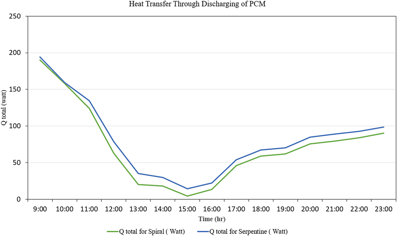
Figure 17: Heat transfer during PCM discharge at a flow rate of 9 L/min
Fig. 18 illustrates the experimental variations in the total heat transfer coefficient (U-value) during an 8-h discharge of phase change material (PCM) heated water via pipes for two floor heating configurations: spiral and serpentine, inside a PCM-augmented thermal storage system. The U-value, expressed in W/m2·K, is an essential parameter for evaluating the system’s ability to transfer heat from the PCM to the surrounding room environment. The serpentine configuration demonstrates consistently enhanced thermal performance over all assessed intervals, with U-values between 2.2 and 2.3 W/m2·K, in contrast to the spiral configuration, which presents lower values ranging from 1.8 to 2.0 W/m2·K. The persistent disparity arises from the extended pipes and increased surface area of the serpentine configuration, which presumably enhances heat transmission via conduction and convection inside the flooring system. Although trends have been largely consistent over time, the serpentine shape has a distinct advantage, underscoring its appropriateness for situations necessitating effective thermal dissipation and swift heat transfer. These results further validate the significance of system geometry in maximising PCM-based passive heating systems, where increasing heat transfer rates is crucial for attaining optimal interior thermal comfort during off-peak or shutdown times.
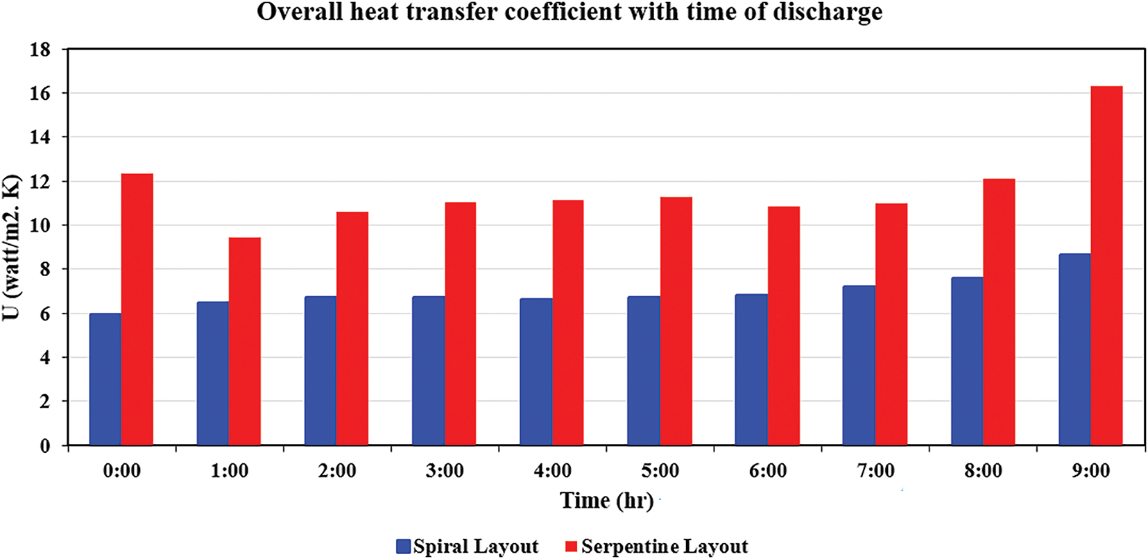
Figure 18: Overall heat transfer coefficient with time discharge at a flow rate of 9 L/min
Fig. 19 illustrates the thermal discharge characteristics of a PCM-integrated system at nighttime, emphasising the output hot water temperature, the average PCM temperature (measured at several points and averaged experimentally), and the ambient temperature. The system depends on latent and sensible energy stored in the PCM, which attains its maximum thermal capacity at 21:00. The output water temperature diminishes more rapidly than the average PCM temperature, leading to an expanding thermal gap. At 07:00, the output temperature drops to 26.61°C, whilst the PCM remains at 30.84°C. This signifies a nonlinear discharge profile, marked by a diminishing rate of heat emission over time. The ambient temperature curve has a continuously lower trend, indicating a stable exterior thermal barrier. The PCM’s ability to maintain a reasonably high interior temperature, despite reductions in water and ambient temperatures, confirms its appropriateness for nocturnal load levelling and comfort preservation in low-energy buildings. This conduct corresponds with thermal storage studies, emphasising the benefits of PCM systems. The findings indicate that PCM-integrated systems may sustain comfort levels without active energy input, hence decreasing HVAC loads and energy consumption.
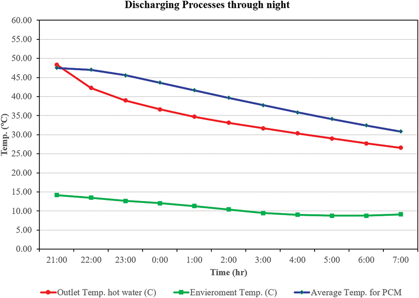
Figure 19: Discharging process through the night at 9 L/min
Fig. 20 depicts experimentally the thermal response of a PCM-enhanced heating system across a two-day duration, emphasizing the charging and discharging cycles alongside a midday shutdown phase. The plot features several temperature profiles, including inlet and outlet water temperatures (T1 and T8), phase change material temperatures at different vertical positions (T3–T7), and ambient environmental temperature (T9). In the initial charging phase (11:00 to 18:00 on Day 1), the inlet water temperature (T1) increases consistently, attaining a maximum of approximately 65°C. The outlet water temperature (T8) exhibits a delayed response, achieving a slightly lower peak, which suggests heat absorption by the phase change material (PCM). The stratified temperature profiles within the PCM (T3–T7) indicate vertical thermal layering, with the center of the PCM (T4) and upper layers (T5–T7) exhibiting faster heating and higher temperatures compared to the bottom layer (T3), attributed to thermal buoyancy and the direction of heat flow. In the discharge phase (18:00 to 08:00), all PCM layers undergo gradual cooling, thereby releasing accumulated thermal energy. The reduced rate of temperature decay in the central and lower PCM regions indicates efficient latent heat storage and a postponement of thermal diffusion. The second charging phase (11:00 to 17:00 on Day 2) demonstrates similar patterns, with slightly steeper temperature rises, potentially as a result of residual storage of energy or external input such as solar gain. A system stabilizing phase from 08:00 to 11:00 demonstrates temperature plateaus and minimal heat exchange activity. The discharge period from 17:00 to 23:00 demonstrates a lowering across all sensors, indicating energy being transferred from the PCM to the external surroundings. The outlet temperature (T8) drops at a higher rate than the PCM core, as would be expected for a thermal-inertia-dominated system. The environmental temperature (T9) stays continuously lower, around an average of 20°C, and thus maintains a constant thermal gradient and facilitates a continuous heat exchanger. The layered sensors provide validation for the efficacy of PCM to delay temperature decline, with the core (T4) and mid layers (T5–T6) providing thermal buffering. This graph illustrates the PCM’s daily cyclic thermal performance, demonstrating its ability to absorb and supply heat at repeated daily intervals. The outcomes confirm the adoption of phase change materials (PCM) for building energy system thermal control, as suited for buildings with high day-night temperature differences or for off-peak winter heating applications.
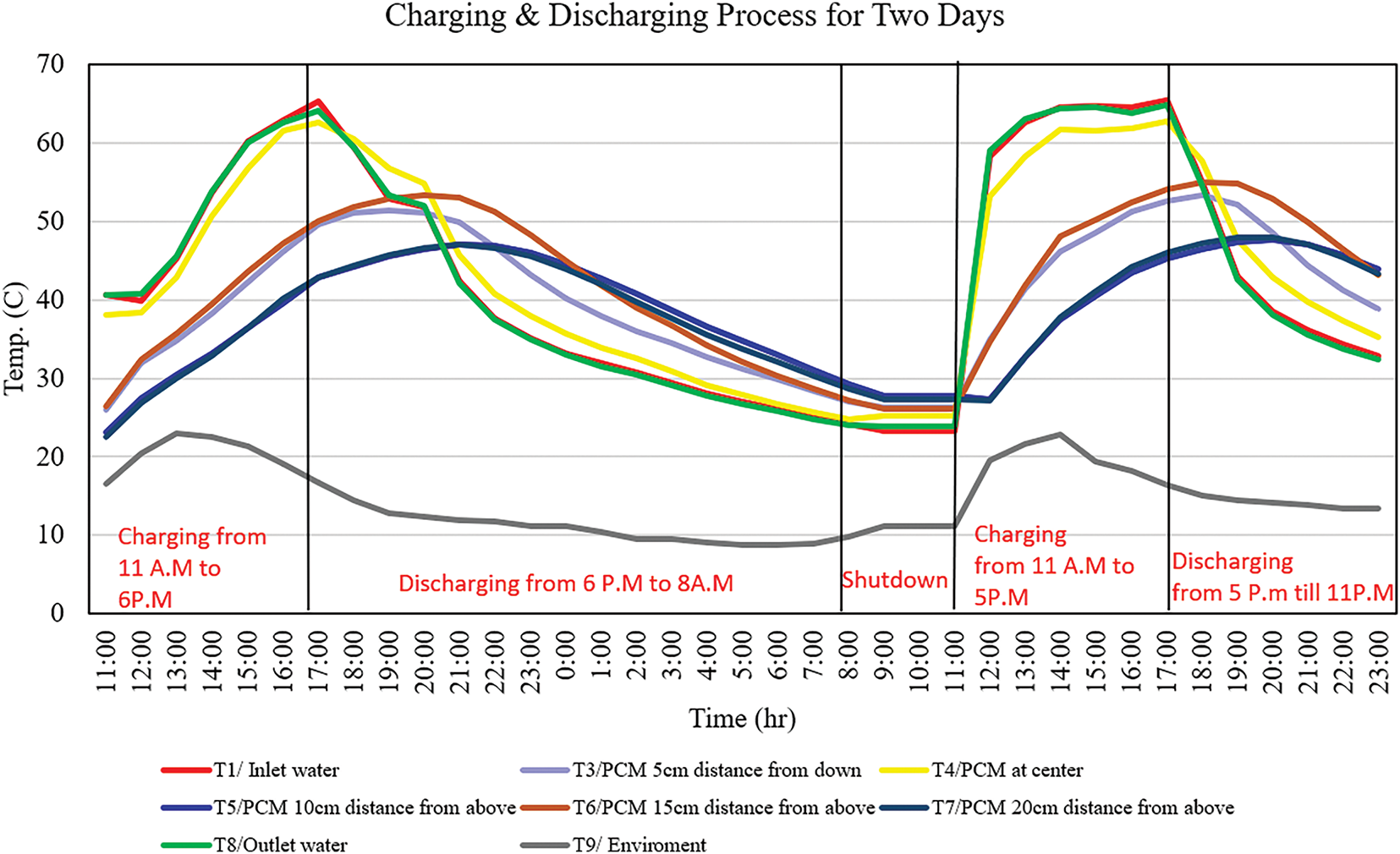
Figure 20: Charging & discharging process experimentally at 9 L/min
In Fig. 21, numerical temperature contours of the PCM charging process, along with stream line at constant flow rate 9 L/min for 5400 s, are illustrated for three various inlet water temperatures of 50°C, 55°C, and 60°C. The convective behaviour and heat distribution of the area are obtained from temperature contours, and they play essential roles in determining the effectiveness of heat extraction from PCM. The distribution of heat remains localised around the heat sources at 50°C, where little heat diffuses through the PCM.

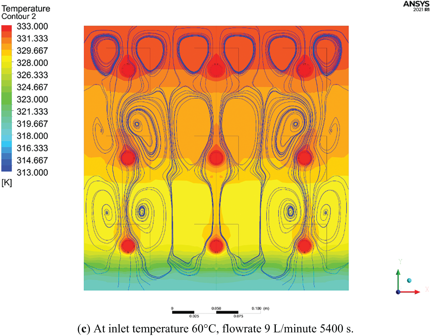
Figure 21: Comparison of countereflow PCM with streamline flow
With increasing temperature up to 55°C, the profiles get longer and connect further, suggesting higher thermal penetration and the formation of stronger natural convection loops. This intermediate case shows increased thermal interaction between adjacent heat zones, indicating a more effective heat extraction and a broader thermal influence range compared to 50°C. At 60°C, a pronounced convective flow is evident. The contours extend vertically and horizontally, demonstrating well-developed convective currents and a more homogeneous temperature field. The red zones are more prominent and widespread, showing that the PCM has undergone significant thermal release. This condition maximizes the heat transfer potential due to the higher driving temperature difference and more extensive liquid-phase formation. Overall, the images highlight that higher inlet temperatures enhance the discharge performance by accelerating convection within the PCM and promoting a more uniform thermal field. The presented image showcases temperature contours overlaid with streamline plots for a PCM thermal storage system under varying inlet temperatures 50°C, 55°C, and 60°C, each operated at a flow rate of 9 L/min for 5400 s. This combined visualization provides a comprehensive depiction of both conductive and convective heat transfer mechanisms within the system, particularly highlighting the impact of buoyancy-driven natural convection during the PCM discharge phase. At 50°C, the temperature contours indicate a predominantly conduction-dominated regime with localized heating zones surrounding the heat sources. The streamlines form compact, symmetrical vortex structures, suggesting minimal buoyancy effects and weak convective circulation within the PCM. The limited development of convection cells implies that the heat extraction process is slow, primarily driven by thermal conduction through solid or semi-solid PCM. Increasing the inlet temperature to 55°C initiates a transition toward stronger convective dominance. The streamline structures become more elongated and dynamic, illustrating intensified fluid motion within the liquid PCM layers. Concurrently, the temperature field expands more significantly throughout the storage domain, evidencing improved heat diffusion and enhanced thermal interaction between neighboring zones. The onset of natural convection facilitates more efficient latent heat release from the PCM matrix. At 60°C, the interaction between thermal and flow fields is most pronounced. The temperature distribution becomes more uniform and elevated, and the streamlines show large, well-formed convective loops that span across the PCM domain. This pattern reflects robust natural convection currents, which effectively transport thermal energy away from the heated regions. The fully developed convective regime significantly accelerates the discharge process, resulting in broader thermal coverage and improved system performance.
In the current study, the flooring assembly comprises five categories, as described previously. PEX pipe material, widely used in such projects due to its long-term durability, ease of installation, and corrosion resistance, was selected for the pipes. The concrete slab retains heat and radiates it into the rooms through the hot-water underfloor heating system. A comparison was made between the inlet and outlet hot water temperatures for each layout, by the NF DTU 65.14 P1 standard (NF DTU 65.14 p1, 2023 [28]). Refer to Fig. 22 for details. This study’s results are comparable to earlier research, specifically those of Yassine & Mohammed (Anigrou and Zouini, 2024 [19]), the inlet temperature between 50°C and 60°C appears to be effective when used in their research. The results show that the serpentine layout in the present work is approximately 20%–25% more effective than in the previous study, while the spiral layout is about 27%–30% more effective compared to the spiral layout in the previous work.
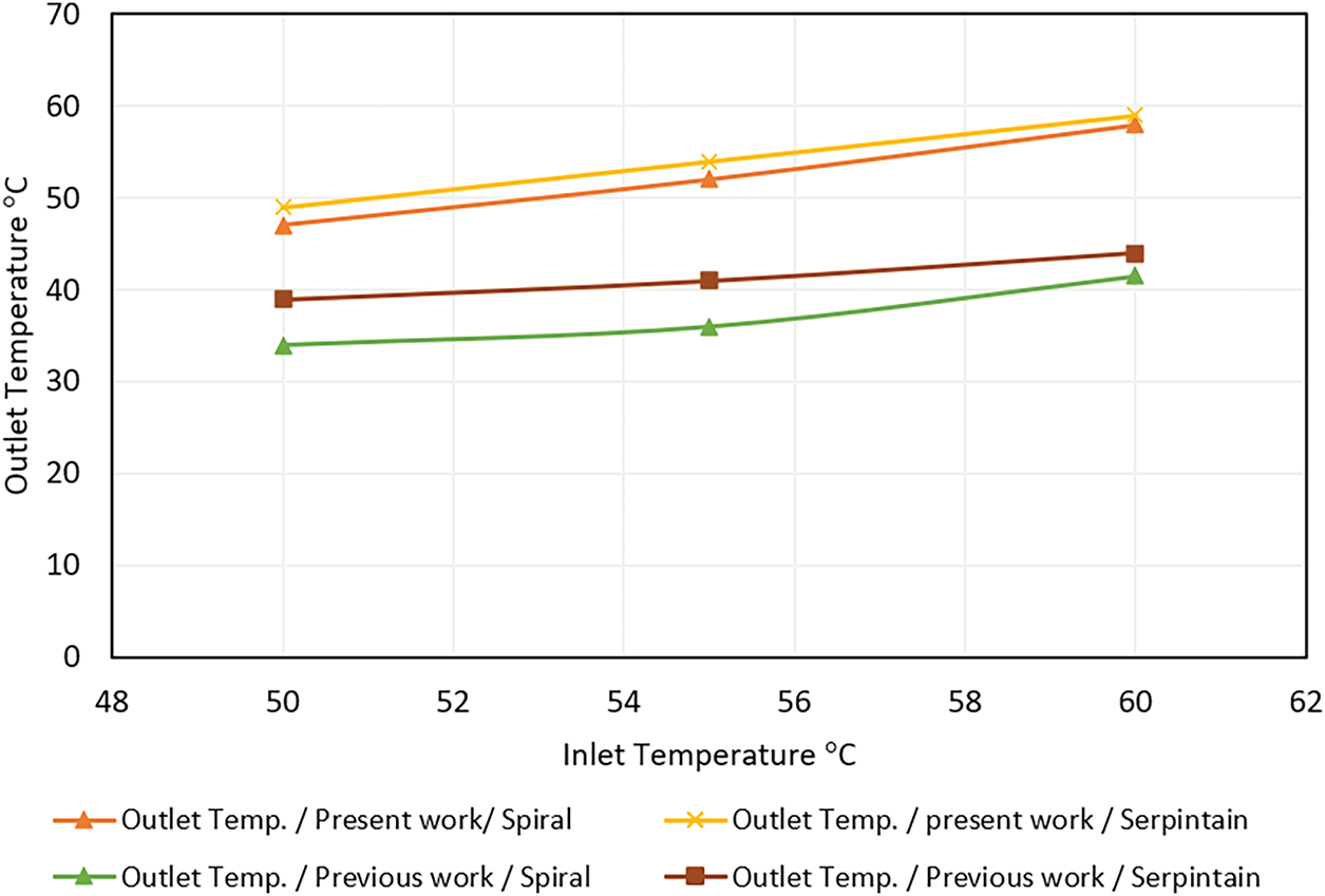
Figure 22: Comparison of temperature distribution inside the slab
This paper presents a thorough experimental and numerical analysis of two different underfloor radiant heating pipe configurations, spiral and double serpentine, integrated with a paraffin wax-based phase change material (PCM) thermal energy storage (TES) system. The findings show that, in terms of heat transfer efficiency, thermal storage capacity, and general heat delivery during both active and passive (discharge) periods, the double serpentine layout consistently outperformed the spiral configuration. Its longer pipe length and higher surface interaction allowed the serpentine layout to show better uniformity in interior temperature, higher heat flux, and higher outlet temperatures. Numerical simulations conducted on ANSYS Fluent also confirmed the experimental findings by showing that higher inlet water temperatures hastened the PCM melting and discharging processes. Sixty degrees Celsius showed the best performance. By reducing temperature variations, the TES system, which is based on PCM, efficiently delays heat release, therefore guaranteeing thermal comfort during inactive heating times and enhancing occupant comfort and energy efficiency. Particularly in energy-constrained settings like Iraq during the winter months, these results highlight the need for thermal boundary conditions and pipe layout geometry in the optimization of PCM-enhanced radiant floor heating systems. Future studies could look at the combination of sophisticated control techniques and renewable energy sources to improve the system’s adaptability and sustainability.
Acknowledgement: The authors would like to thank the mechanical department at Engineering Collage of University of Baghdad for their support.
Funding Statement: The authors received no specific funding for this study.
Author Contributions: The authors confirm their contribution to the paper as follows: study conception and design: Najim A. Jasim; data collection: Rafah H. Zaidan, Najim A. Jasim; analysis and interpretation of results: Rafah H. Zaidan, Najim A. Jasim; draft manuscript preparation: Rafah H. Zaidan. All authors reviewed the results and approved the final version of the manuscript.
Availability of Data and Materials: The data that support the findings of this study are available from the corresponding author upon reasonable request.
Ethics Approval: Not applicable.
Conflicts of Interest: The authors declare no conflicts of interest to report regarding the present study.
Nomenclature
| CP | Specific heat, J·kg−1·K−1 |
| g | Gravitational acceleration, m·s−2 |
| λ | Thermal conductivity, W/m·K |
| Nu | Local Nusselt number |
| α | Thermal diffusivity, m2·s−1 |
| β | Coefficient of thermal expansion, K−1 |
| ν | Kinamatic viscocity, m2·s−1 |
| µ | Dynamic viscosity, kg·m−1·s−1 |
| s | Slab |
References
1. Liang X, Shim J, Song D. A simple and efficient machine-learning based approach for optimal heating control of radiant floor heating systems: proposal and validation. Build Environ. 2025;272(3):112666. doi:10.1016/j.buildenv.2025.112666. [Google Scholar] [CrossRef]
2. Baek S, Kim S. Analysis of thermal performance and energy saving potential by PCM radiant floor heating system based on wet construction method and hot water. Energies. 2019;12(5):828. doi:10.3390/en12050828. [Google Scholar] [CrossRef]
3. Park J, Kim T. Analysis of the thermal storage performance of a radiant floor heating system with a PCM. Molecules. 2019;24(7):E1352. doi:10.3390/molecules24071352. [Google Scholar] [PubMed] [CrossRef]
4. Zhao J, Ji Y, Yuan Y, Zhang Z, Lu J. Seven operation modes and simulation models of solar heating system with PCM storage tank. Energies. 2017;10(12):2128. doi:10.3390/en10122128. [Google Scholar] [CrossRef]
5. González B, Prieto MM. Radiant heating floors with PCM bands for thermal energy storage: a numerical analysis. Int J Therm Sci. 2021;162:106803. doi:10.1016/j.ijthermalsci.2020.106803. [Google Scholar] [CrossRef]
6. Lu S, Xu B, Tang X. Experimental study on double pipe PCM floor heating system under different operation strategies. Renew Energy. 2020;145(31):1280–91. doi:10.1016/j.renene.2019.06.086. [Google Scholar] [CrossRef]
7. Larwa B, Cesari S, Bottarelli M. Study on thermal performance of a PCM enhanced hydronic radiant floor heating system. Energy. 2021;225(2):120245. doi:10.1016/j.energy.2021.120245. [Google Scholar] [CrossRef]
8. Kong X, Chang Y, Fan M, Li H. Analysis on the thermal performance of low-temperature radiant floor coupled with intermittent stratum ventilation (LTR-ISV) for space heating. Energy Build. 2023;278(1):112623. doi:10.1016/j.enbuild.2022.112623. [Google Scholar] [PubMed] [CrossRef]
9. Beiranvand M, Mohaghegh MR. Energy analysis and simulation of PCM-enhanced building envelopes in commercial buildings: a case study. Energy Storage. 2021;3(4):e246. doi:10.1002/est2.246. [Google Scholar] [CrossRef]
10. Hasan HA, Hassoon AS. Thermal performance investigation of finned latent heat storage of shell-and-tube, shell-and-nozzle, and shell-and-reducer models. Heat Transf. 2023;52(7):4755–73. doi:10.1002/htj.22906. [Google Scholar] [CrossRef]
11. Hussien FM, Hassoon AS, Faraj JJ. Performance analysis of a triple pipe heat exchanger with phase change materials for thermal storage. Int J Heat Technol. 2023;41(3):619–28. doi:10.18280/ijht.410314. [Google Scholar] [CrossRef]
12. de Gracia A, Cabeza LF. Phase change materials and thermal energy storage for buildings. Energy Build. 2015;103:414–9. doi:10.1016/j.enbuild.2015.06.007. [Google Scholar] [CrossRef]
13. Nazir H, Batool M, Bolivar Osorio FJ, Isaza-Ruiz M, Xu X, Vignarooban K, et al. Recent developments in phase change materials for energy storage applications: a review. Int J Heat Mass Transf. 2019;129(48):491–523. doi:10.1016/j.ijheatmasstransfer.2018.09.126. [Google Scholar] [CrossRef]
14. Zhang Y, Chen C, Jiao H, Wang W, Shao Z, Qi D, et al. Thermal performance of new hybrid solar energy-phase change storage-floor radiant heating system. Procedia Eng. 2016;146:89–99. doi:10.1016/j.proeng.2016.06.357. [Google Scholar] [CrossRef]
15. Agarwal S, Anand V, Banker ND, Biswal P. Experimental studies on space heating using phase change material. Energy Storage. 2021;3(2):e209. doi:10.1002/est2.209. [Google Scholar] [CrossRef]
16. Rashid FL, Hussein AK, Al-Obaidi MA, Alshammari BM, Ali B, Hajlaoui R, et al. A review of radiant heating and cooling systems incorporating phase change materials. J Therm Anal Calorim. 2024;149(15):7891–917. doi:10.1007/s10973-024-13193-6. [Google Scholar] [CrossRef]
17. Al-Hinti I, Al-Ghandoor A, Maaly A, Abu Naqeera I, Al-Khateeb Z, Al-Sheikh O. Experimental investigation on the use of water-phase change material storage in conventional solar water heating systems. Energy Convers Manag. 2010;51(8):1735–40. doi:10.1016/j.enconman.2009.08.038. [Google Scholar] [CrossRef]
18. Liu J, Yang Y, Li A, Wang W, Wu W, Zhang H. Preparation and assessment of a novel hydrated salt PCM applied for intermittent floor radiant heating systems. J Energy Storage. 2025;105:114710. doi:10.1016/j.est.2024.114710. [Google Scholar] [CrossRef]
19. Anigrou Y, Zouini M. Comparative numerical study of floor heating systems using parallel and spiral coil. Sci Afr. 2024;24(11):e02188. doi:10.1016/j.sciaf.2024.e02188. [Google Scholar] [CrossRef]
20. Oubenmoh S, Allouhi A, Ait Mssad A, Saadani R, Kousksou T, Rahmoune M, et al. Some particular design considerations for optimum utilization of under floor heating systems. Case Stud Therm Eng. 2018;12(6):423–32. doi:10.1016/j.csite.2018.05.010. [Google Scholar] [CrossRef]
21. CFD Online. K-epsilon models [Internet]. [cited 2025 Aug 13]. Available from: https://cfd-online.com/Wiki/K-epsilon_models. [Google Scholar]
22. Ahsan M. Numerical analysis of friction factor for a fully developed turbulent flow using k–ε turbulence model with enhanced wall treatment. Beni Suef Univ J Basic Appl Sci. 2014;3(4):269–77. doi:10.1016/j.bjbas.2014.12.001. [Google Scholar] [CrossRef]
23. Jasim QK, Jassim NA. Thermal performance of radiant floor cooling system with phase change material [dissertation]. Baghdad, Iraq: University of Baghdad; 2023. [Google Scholar]
24. Soibam J. Numerical Investigation of a Phase Change Materials (PCM) heat exchanger [master’s thesis]. Trondheim, Norway: Norwegian University of Science and Technology; 2017. [Google Scholar]
25. Olesen BW. Radiant floor heating in theory and practice. Ashrae J. 2002;44:19–26. [Google Scholar]
26. Hassan AK, Abdulateef J, Mahdi MS, Hasan AF. Experimental evaluation of thermal performance of two different finned latent heat storage systems. Case Stud Therm Eng. 2020;21(2):100675. doi:10.1016/j.csite.2020.100675. [Google Scholar] [CrossRef]
27. Moffat RJ. Describing the uncertainties in experimental results. Exp Therm Fluid Sci. 1988;1(1):3–17. doi:10.1016/0894-1777(88)90043-X. [Google Scholar] [CrossRef]
28. NF DTU 65.14 P1-1-2. Building works-Execution works of heated, refreshing and reversible water floors with disassociated Insulated slabs—part 1-1-2: contract bill of technical model clauses. Paris, France: Afnor; 2023. [Google Scholar]
Cite This Article
 Copyright © 2025 The Author(s). Published by Tech Science Press.
This work is licensed under a Creative Commons Attribution 4.0 International License , which permits unrestricted use, distribution, and reproduction in any medium, provided the original work is properly cited.
 Downloads
 Citation Tools