
 Submit a Paper
 Propose a Special lssue
 Open Access
ARTICLE

Comprehensive Study of the Effect of Ribs and Cavities on Thermal-Hydraulic Performance of Mini-Channel Heat Sinks
School of Intelligent Manufacturing, Chengdu Technological University, Chengdu, 611730, China
* Corresponding Author: Wenling Liao. Email:
Frontiers in Heat and Mass Transfer 2025, 23(5), 1395-1415. https://doi.org/10.32604/fhmt.2025.069454
Received 23 June 2025; Accepted 13 August 2025; Issue published 31 October 2025
 View Full Text
 Download PDF
Abstract
In this work, numerical simulations are performed to investigate the influence of combining ribs and triangular cavities on the thermal-hydraulic performance (THP) of MCHS at fluid velocities ranging from 1 to 4 m/s (corresponding to Reynolds numbers (Re) of 129.75 to 519). Specifically, the ribs are positioned on the bottom wall, and the rib width is equal to the mini-channel width, while the triangular cavities are arranged on the two side walls of the MCHS. By analyzing and comparing key parameters such as velocity distribution, streamline patterns, pressure drop, skin friction coefficient (Cf), Nusselt number (Nu), friction factor (f), temperature fields, and performance evaluation criterion (PEC), the advantages of rib-cavity coupling configuration in enhancing THP are systematically discussed. Furthermore, the effects of cavity distribution (left, middle, and right), cavity depth (0.04, 0.06, and 0.08 mm), and rib height (0.02, 0.04, and 0.06 mm) on THP are analyzed to optimize the geometric parameters of the ribs and the cavities. The numerical simulation results indicate that, in comparison to the use of ribs or cavities alone, rib-cavity coupling can further improve the THP of MCHS without causing a significant increase in pressure drop. The downstream wall of the cavity is perpendicular to the flow direction which is more favorable for enhancing the heat transfer performance. Increasing the cavity depth improves the heat transfer performance of MCHS, the maximum Nu ratio increase by 35% at a rib height of 0.06 mm. However the increase in the rib height leads to a significant increase in the pressure drop, which in turn exerts a negative impact on THP, a maximum PEC of 1.198 is obtained at a rig height of 0.02 mm. The greatest improvement in THP, reaching 19.8%, is achieved when the cavity depth is 0.08 mm and the rib height is 0.02 mm.Keywords
Heat sink is a specially designed device or structure whose core function is to efficiently absorb and dissipate heat transferred from a heat source (such as electronic components, mechanical parts, or high-temperature equipment) by expanding heat dissipation area, optimizing heat transfer paths, or enhancing fluid flow, thereby maintaining the heat source within a safe operating temperature range. Owing to the advantages of lightweight, compact structure, and high heat transfer area ratio, mini-channel heat sinks (MCHS) have been widely used in fields such as electronic equipment cooling, aerospace and power systems, et al. [1,2]. In recent years, although the continuous advancement of technology has significantly improved the cooling performance of electronic devices, the simultaneous increase in their power consumption has imposed higher demands on heat dissipation capabilities [3]. To address this challenge, various approaches have been proposed to enhance the heat transfer performance of MCHS, including changing the cross-sectional shape [4–9], introducing ribs or pins [10–14], and replacing work fluid [15,16], wavy channel [17–19], and multi-layer mini-channel [20,21].
Among these approaches, changing the cross-sectional shape and introducing ribs or pins, as there is no need for external energy consumption, has attracted great attention from researchers. Sui et al. [22–24] employed numerical simulation and experimental methods to analyze the THP of rectangular wave mini-channels The results confirmed that the wave cross-sectional shape can remarkably enhance the heat transfer performance of MCHS, and the improvement in the heat transfer exceeding the pressure drop penalty. Yuan et al. [25] conducted numerical simulations to investigate the effect of non-uniform waviness on the heat transfer performance of MCHS. The results indicate that the mini-channel with divergent waviness exhibits superior heat transfer performance. Chai et al. [26] evaluated the impact of periodically expanding-contracting cross-section shapes on the heat transfer performance of MCHS, reporting that such configurations result in an average Nu that is 1.8 times higher than that of traditional MCHS. Kumar et al. [27] designed a novel circular wavy mini-channel and utilized numerical simulations to compare the effects of circular and sinusoidal waviness on the heat transfer performance of MCHS. The results reflect that the heat transfer performance of circular wavy MCHS is superior to that of sinusoidal wavy MCHS. Ahmed and Ahmed [28] performed numerical simulations to evaluate the impact of rectangular, triangular, and trapezoidal grooves on the heat transfer performance of MCHS. The results show that compared to rectangular and triangular grooves, trapezoidal grooves have the most significant improvement in the heat transfer performance. In addition, many numerical simulations and experiments have been conducted to analyze the impact of pins or fins on the heat transfer performance of MCHS. For instance, Xiao et al. [29] conducted numerical simulations to analyze the effects of V-shaped ribs on turbulent heat transfer in MCHS. The results indicate that V-shaped ribs can significantly enhance the turbulence effect and convective heat transfer performance of MCHS by inducing longitudinal swirls. Chai et al. [14,30] employed numerical simulations to analyze the influence of triangular and fan-shaped ribs on the heat transfer performance of MCHS. The numerical simulation results reveal that under low Reynolds number (Re) conditions, MCHS with triangular ribs achieve optimal THP, whereas fan-shaped ribs can significantly improve the THP of MCHS under high Re conditions. Hsieh et al. [31] conducted experiments to investigate the effect of pins with different shapes on the heat transfer performance of MCHS under low Re conditions. Their findings indicate that, compared with smooth microchannels, square pins yield the most significant improvement in heat transfer performance, followed by the elliptical, circular, hexagonal, and triangular pins, in that order. Hua et al. [32] conducted experiments to examine the effect of pins with different shapes on flow characteristics in MCHS, demonstrating that circular pins induce greater fluid flow resistance than elliptical pins. Chen et al. [33] analyzed the effects of the distribution direction, height, and offset value of the triangular prism on the flow characteristic and heat transfer performance of MCHS with a Re ranging from 211 to 884. They found that the optimal THP of MCHS is achieved when the prism height Hp = 1 mm and the offset value S = 0 mm.
Furthermore, to maximize the heat transfer performance of MCHS while controlling the pressure drop within a reasonable range, numerical simulations have also been employed to analyze the effects of combining ribs and cavities on the THP of MCHS. Zhu et al. [3] found that by integrating the advantages of rectangular cavities (which increase the flow area and reduce pressure drop) and fins (which enhance fluid disturbance and improve heat transfer), the cavity-fin combination can effectively boost the heat transfer performance of MCHS without increasing the pressure drop. Additionally, Zhu et al. [34] also analyzed the effects of rib type, distribution, and size on the heat transfer performance of MCHS. Datta et al. [35] conducted numerical simulations to assess the effect of the combination of trapezoidal cavities and ribs on the conjugate heat transfer performance of MCHS, revealing that this combination can effectively improve the conjugate heat transfer effect of MCHS and that rib type also exerts a significant impact on conjugate heat transfer. Li et al. [36–39] further confirmed the superiority of the cavity-fin combination in improving the heat transfer performance of MCHS.
In summary, how to effectively improve the heat transfer performance of MCHS without causing a significant increase in fluid pressure drop remains a focus of current research. Although researchers have conducted numerical simulation studies on the combination of ribs and cavities to improve the THP of mini-channel heat sinks, rib dimensions is a critical factor affecting the heat transfer performance. At present, existing studies focused on the rib widths smaller than the mini-channel width, with a lack of research investigating scenarios where the rib width is equal to the mini-channel width. Therefore, this work performs numerical simulations to analyze the impact of the combining ribs and cavities on the THP of MCHS under the condition that the rib width equals the mini-channel width. Specially, the ribs and cavities are located on the bottom wall and the two side walls of the mini-channel, respectively. Based on the analysis of velocity distribution, streamline patterns, pressure drop, Cf, Nu, f, temperature fields, and PEC, the impact mechanism of the combination of ribs and cavities on the THP of MCHS is analyzed in detail.
Fig. 1 shows the schematic diagram of the geometric structure of MCHS, the overall size of MCHS is 10
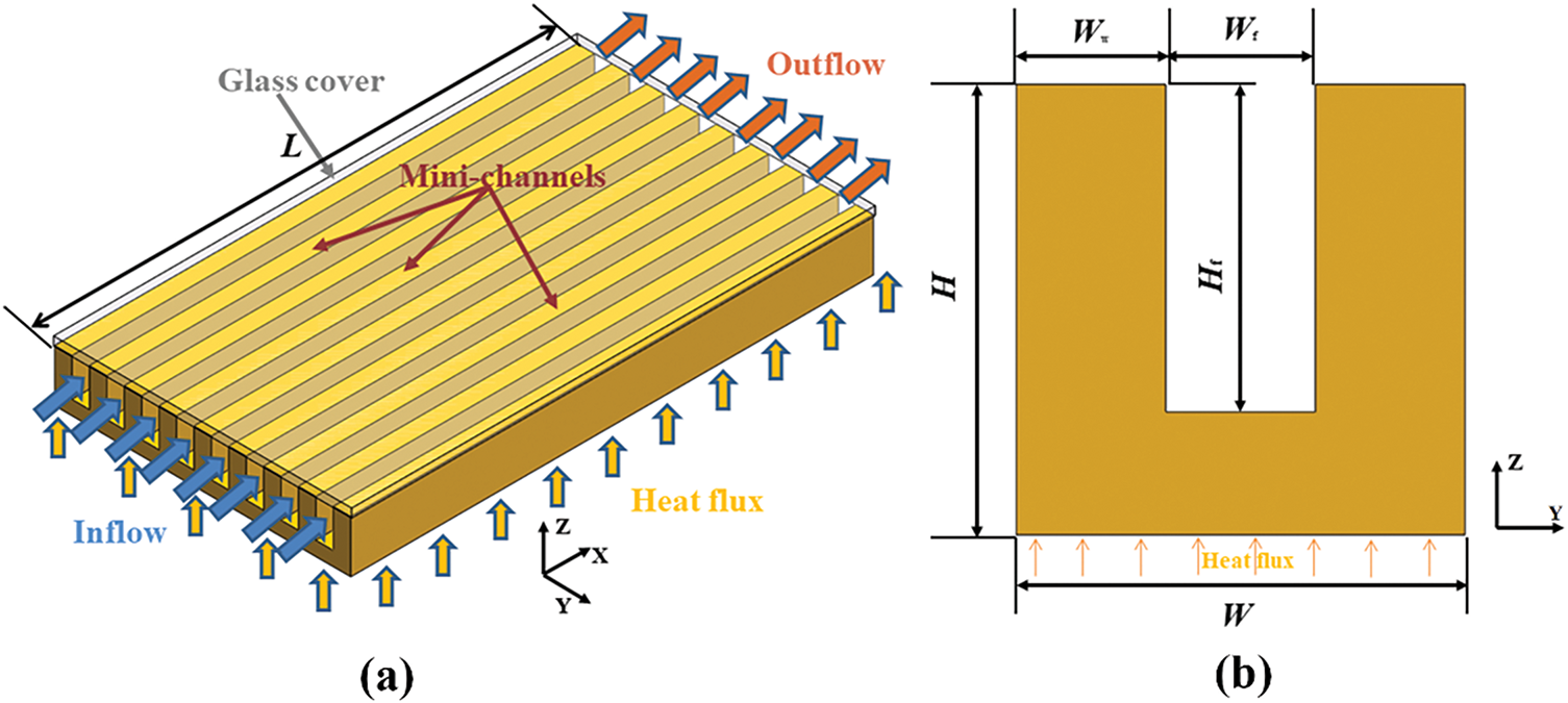
Figure 1: (a) Isometric view of mini-channels, and (b) cross-sectional view of a single mini-channel
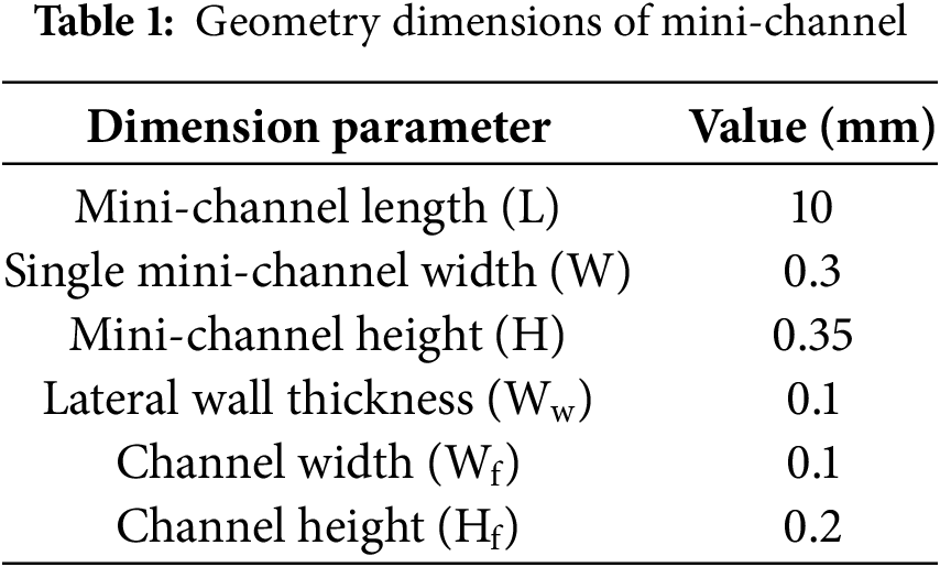
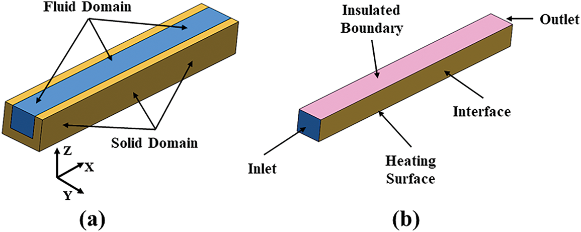
Figure 2: (a) The fluid domain, and (b) boundary setting conditions
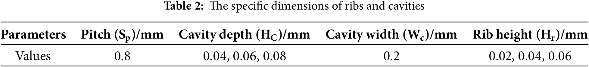
In heat transfer, a rib is a protruding structure intentionally designed on a solid surface to enhance heat exchange between the surface and the surrounding fluid. It is typically integrally formed with the base surface or attached via welding, bonding, etc. A cavity refers to a closed or semi-closed space enclosed by solid boundaries, typically filled with gas, liquid, or vacuum, where the spatial scale is comparable to or larger than the characteristic scale of the heat transfer process. Given the small size of MCHS, triangular cross-section is adopted for the cavities on both sides of the mini-channel to facilitate the fabrication of cavities. The ribs, located on the bottom wall of the mini-channel, have the same cross-sectional shape as the cavities. Fig. 3 shows a schematic diagram of the geometry of the mini-channel incorporating ribs and cavities. Additionally, three different cavity distributions are designated as cavity left (C-L), cavity-middle (C-M), and cavity-right (C-R) to distinguish their positional differences. The specific dimensions of the ribs and cavities are shown in Table 2. To distinguish the influence of rib height on THP, different rib heights are represented as R0.02, R0.04, and R0.06, respectively. Similarly, different cavity depths are represented as C0.04, C0.06, and C0.08, respectively.
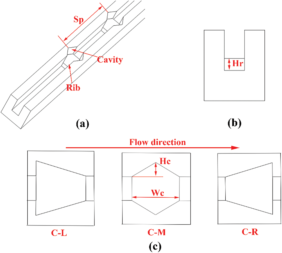
Figure 3: The schematic diagram of the geometry of ribs and cavities: (a) axonometric view, (b) home view, and (c) side view
2.2 Numerical Model and Boundary Conditions
According to the research reported by Palm et al. [40], the single-phase flow in the mini-channel still obeys the N-S equation and continuity assumption when the hydraulic diameter is larger than 1
Continuity equation:
Momentum equation:
The energy equation for the fluid domain:
The energy equation for the solid domain:
In this work, the water is used as a working fluid to investigate the flow characteristics and heat transfer performance in mini-channels. The impact of temperature changes on the physical properties of water is neglected. In addition, the boundary conditions of the numerical simulation are written as follows:
(1) Inlet (x = 0): The velocity-inlet boundary condition is applied to the mini-channel inlet.
The fluid with a temperature of 300 K. Refer to existing literature [3,41], the fluid velocity is set to 1, 1.5, 2, 2.5, 3, 3.5, and 4 m/s, and the corresponding Re are 129.75, 194.62, 259.5, 324.37, 389.25, 454.12, and 519, respectively.
(2) Outlet (x = L): The pressure-outlet boundary condition is applied to the mini-channel outlet.
The pressure setting at the microchannel outlet is equal to atmospheric pressure.
(3) Contact surfaces of fluid and solid: The conjugate boundary condition is applied to the internal surface.
(4) Bottom wall (z = 0): The no-slip and uniform heat flux condition is applied to the bottom wall, the heat flux is
(5) Symmetry surface (
(6) Other surfaces: The no slip and no heat transfer conditions are applied to other surfaces.
2.3 Data Acquisition and Performance Evaluation
To effectively compare and evaluate the simulation results, the following parameters are explained.
Reynolds number (Re): After determining the geometric parameters of the mini-channel and the working fluid, Re can be calculated from the fluid velocity at the inlet.
(Skin friction coefficient)
(Nusselt number) Nu: The heat transfer performance of mini-channels is evaluated by Nu.
(Friction factor) f: The f is used to quantitatively describe the flow characteristics of the fluid, which can be described as:
(Performance evaluation criterion) PEC: PEC is used to quantitatively describe the THP of microchannels, which can be given by Ref. [42]:
In Eqs. (9)–(15),
2.4 Grid Independence and Model Validation
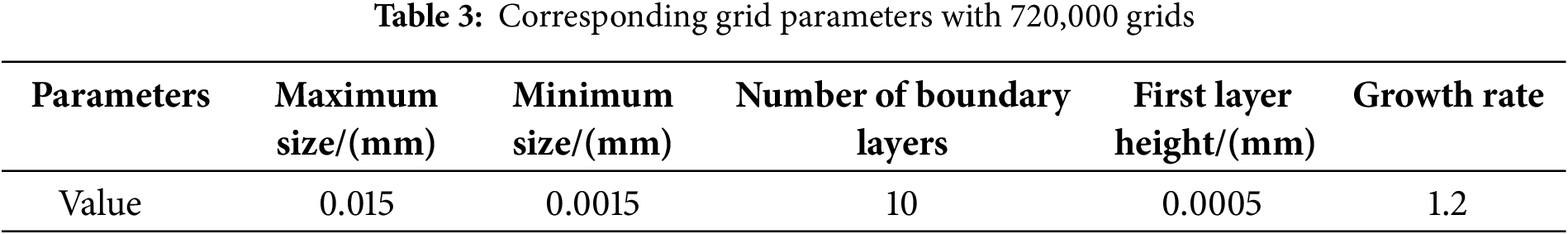
In this work, the mesh division is performed by using Fluent Meshing. Fig. 4 shows the schematic diagram of grid. As shown in Fig. 4, the near-wall mesh is encrypted to capture the flow characteristics of the near-wall fluid as much as possible. The effect of five different grid numbers on computational accuracy as shown in Fig. 5. It can be seen that as the number of grids reaches 600,000, the increase in the grid number has very little impact on the error of calculation result. When the grid number is between 720,000 and 840,000, the error percentage of Nu and f is less than 0.43% and 0.44%, respectively. Therefore, to ensure computational accuracy and save computational cost, the mesh parameters of 720,000 are adopted for the mesh division of the geometric model, The specific grid parameters are shown in Table 3.
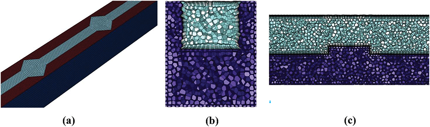
Figure 4: Schematic diagram of grid: (a) axonometric view, (b) home view, and (c) side view
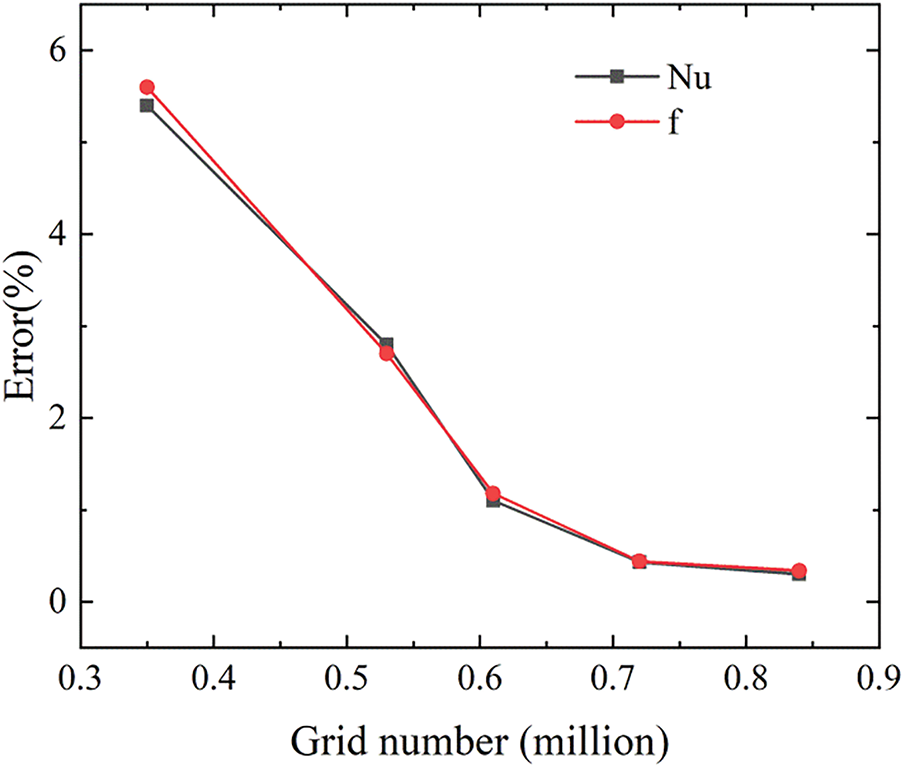
Figure 5: Effect of grid number on calculation error at Re = 454
The accuracy of the simulation method is verified before conducting numerical simulation. Fig. 6 shows the comparison of Nu and fRe between the simulation results and the experimental results reported by Chai et al. [43]. It is evident that a good agreement between the simulation results and experimental results has been observed within the Re range of 150 to 650. The maximum deviations of Nu and fRe for simulation results and experimental date are 2.2% and 2.6%, respectively, which confirms the feasibility of using simulation methods for the analysis of THP of MCHS.
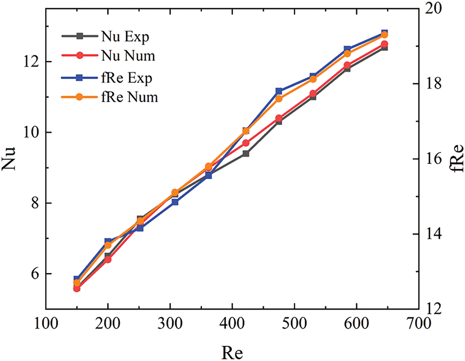
Figure 6: Comparison of numerical results and experimental data
To comprehensively evaluate the advantages of rib-cavity coupling in enhancing the THP of MCHS, the influence of ribs alone, cavities alone, and rib-cavity synergy on flow characteristics and heat transfer performance of MCHS has been analyzed. Fig. 7 displays the velocity distribution in mini-channels with ribs, cavities, and rib-cavity combinations at Re = 519. Under the constraint of constant flow rate, the introduction of ribs or cavities alters the cross-sectional area of the mini-channel, leading to periodic fluctuations in fluid velocity along the flow direction. However, the differential effects of ribs and cavities on the cross-sectional area also result in distinct patterns of velocity fluctuation. For the R0.02 configuration (rib height = 0.02 mm), the maximum velocity occurs at the mini-channel cross-section near the ribs, as the ribs narrow the fluid flow region, while the minimum velocity is observed in the upstream and downstream regions of the ribs. For the C0.08 configuration (cavity depth = 0.08 mm), owing to the expansion of the flow cross-sectional area caused by the cavities, the minimum velocity is located near the cavity cross-section of the mini-channel. For the R0.02-C0.08 combined configuration, the mini-channel cross-sectional area remains enlarged after rib-cavity coupling, resulting in a slight reduction in velocity within the channel. Furthermore, compared with the R0.02 and C0.08 configurations, the R0.02-C0.08 configuration exhibits a more irregular velocity distribution perpendicular to the fluid flow direction.
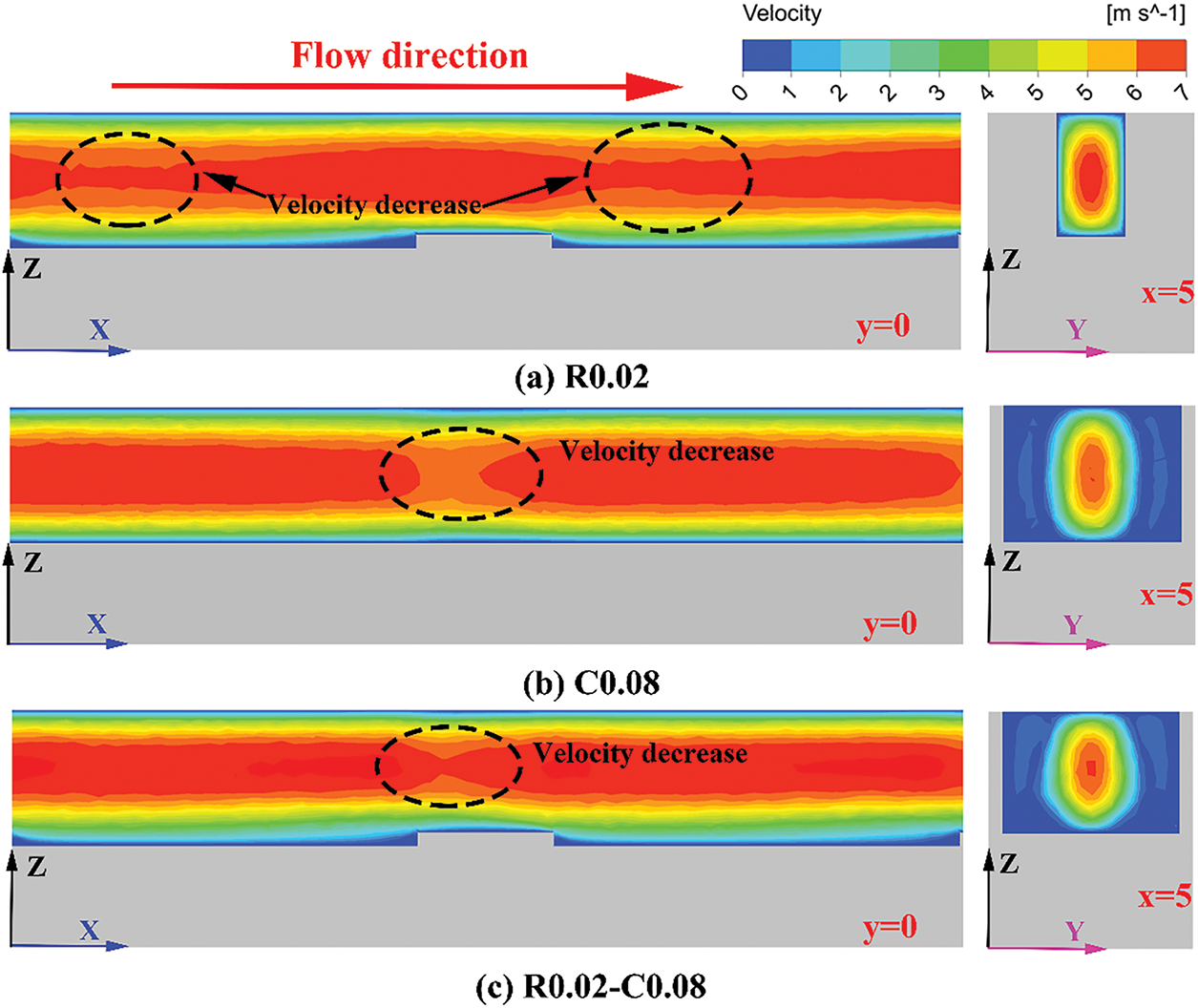
Figure 7: Velocity contours on the y = 0 and x = 5 planes for R0.02, C0.08, and R0.02-C0.08. Configurations at Re = 519: (a) R0.02, (b) C0.08, and (c) R0.02-C0.08
Fig. 8 depicts the two-dimensional streamline distributions on the x = 5 mm plane for R0.02, C0.08, and R0.02-C0.08 configurations at Re = 519. Evidently, for the R0.02 configuration, fluid fluctuations induced by the ribs enhance fluid mixing between the near-bottom wall region and the central region of the mini-channel. For the C0.08 configuration, the cavities promote fluid mixing between the near-side wall region and the central region but exert negligible influence on fluid mixing near the bottom wall. In contrast, for the R0.02-C0.08 configuration, the coupling of ribs and cavities resulting in fluid mixing within the mini-channel that integrates the effects of ribs and cavities on fluid flow. Specially, fluid near both the bottom and side wall exhibits enhanced mixing effect with the fluid in the central region, which is more conducive to improving the heat transfer efficiency of MCHS.
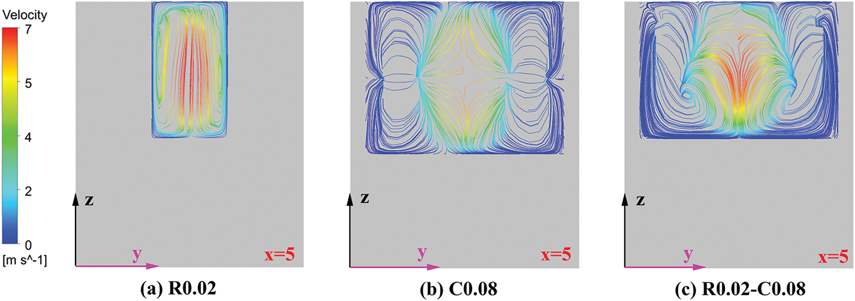
Figure 8: Two-dimensional streamline distributions on the x = 5 planes for R0.02, C0.08, and R0.02-C0.08 configurations at Re = 519: (a) R0.02, (b) C0.08, and (c) R0.02-C0.08
Fig. 9 compares the pressure variation along the flow direction in three types of mini-channels. Under the same outlet pressure condition, notable differences are observed in the inlet pressure of the three types of mini-channels. The inlet pressure of the R0.02-C0.08 configuration is the highest, followed by that of R0.02 and C0.08, respectively. This phenomenon is primarily attributed to the significant flow obstruction induced by ribs. When coupled with cavities, the intensified fluid disturbance further enhances this obstruction effect. Moreover, compared to cavities, ribs generate greater flow resistance in the mini-channel. Therefore, special attention should be paid to the impact of ribs on fluid flow during the design process.
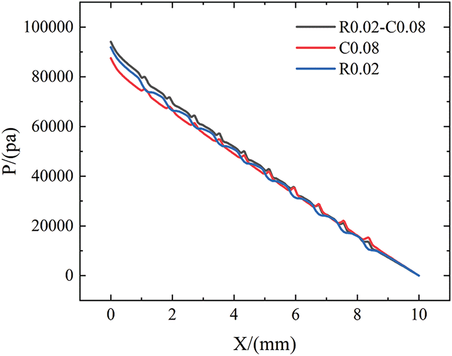
Figure 9: Variations of pressure vs x for R0.02, C0.08, and R0.02-C0.08 configurations at Re = 519
Fig. 10 compares the skin friction coefficient (Cf) of the R0.02, C0.08, and R0.02-C0.08 configurations at Re = 519. It is observed that Cf exhibits periodic fluctuations, which can be attributed to the periodic distribution of ribs and cavities. However, the Cf relationship between the two sides and bottom walls of the three types of mini-channels is not consistent. For the bottom wall (Fig. 10a), the R0.02 configuration yields the highest average Cf, followed by R0.02-C0.08 and C0.08, respectively. Furthermore, in both the R0.02 and R0.02-C0.08 configurations, the maximum Cf occurs on the upstream side of the rib, which is attributed to the impact effect of the fluid on this region. As shown in Fig. 10b, the R0.02-C0.08 configuration exhibits the highest average Cf on the side wall, followed by C0.08 and R0.02. The maximum Cf of R0.02-C0.08 and C0.08 is located on the downstream side of the cavity, which is attributed to the flow attachment of the fluid in the region. Conversely, the minimum Cf in R0.02-C0.08 and C0.08 is observed at the central region of the cavity. This phenomenon is due to the low fluid velocity in the cavity area, resulting in the thickest fluid boundary layer.
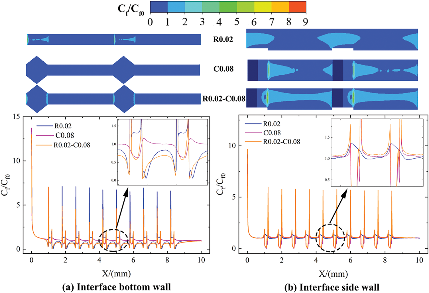
Figure 10: Normalized Cf contours and profiles on the wall for R0.02, C0.08, and R0.02-C0.08 configurations at Re = 519: (a) interface bottom wall, (b) interface side wall
Fig. 11 shows the Nu contours of R0.02, C0.08, and R0.02-C0.08 configurations at Re = 519. Consistent with the Cf comparison results of the three types of mini-channels discussed above, the regions of maximum Nu within the mini-channel correspond one-to-one with those of maximum Cf. Besides, the average Nu values follow the order: Nu (R0.02-C0.08) > Nu (C0.08) > Nu (R0.02). The phenomenon indicates that the synergistic heat transfer enhancement achieved by the combination of ribs and cavities is superior to that of ribs or cavities acting alone.
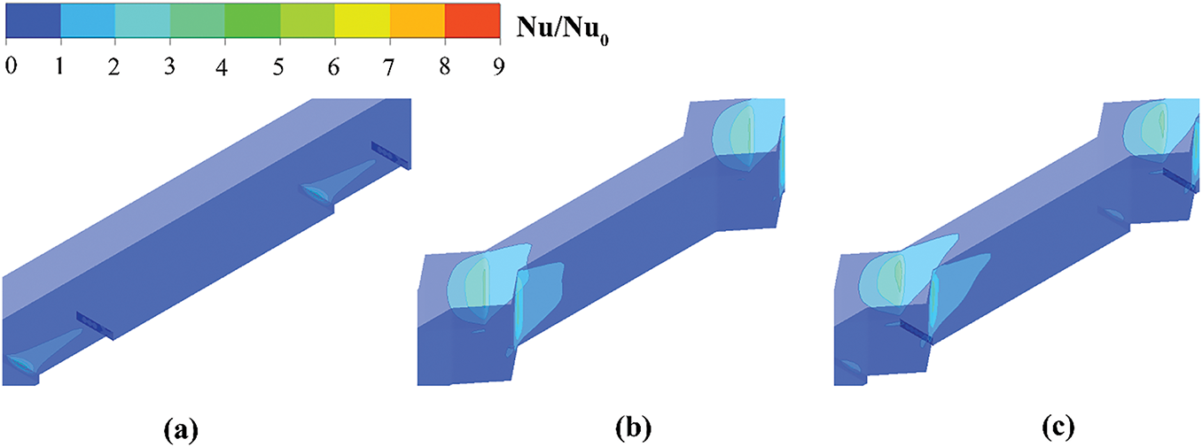
Figure 11: Normalized Nu contours on the wall for R0.02, C0.08, and R0.02-C0.08 configurations at Re = 519: (a) R0.02, (b) C0.08, and (c) R0.02-C0.08
Fig. 12 displays the temperature contours of the R0.02, C0.08, and R0.02-C0.08 configurations at Re = 519. The average fluid temperature in R0.02-C0.08 configuration is the highest, followed by that in C0.08 and then R0.02. Consequently, MCHS with coupled ribs and cavities has the best heat transfer enhancement, indicating that the coupling of ribs and cavities can integrate the advantages of ribs and cavities in enhancing the heat transfer, further improving the heat transfer effect of MCHS without significantly increasing the pressure drop.
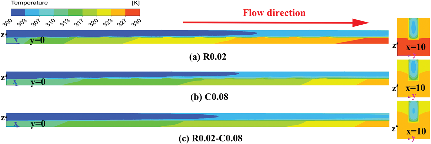
Figure 12: Temperature contours on the y = 0 and outlet planes for R0.02, C0.08, and R0.02-C0.08 configurations at Re = 519: (a) R0.02, (b) C0.08, and (c) R0.02-C0.08
The combination of rib and cavity has different effects on the heat transfer performance and pressure drop, and the pressure drop is not necessarily optimal when the heat transfer performance is optimal, so it is necessary to select the appropriate rib and cavity structure according to the specific situation [44]. To further optimize the geometric parameters of ribs and cavities for enhanced heat transfer, the effects of the cavity distribution, cavity depth, and rib height are systematically discussed in the subsequent sections.
3.3 Effect of Cavity Distribution
Fig. 13 shows the influence of cavity distribution on velocity distribution in mini-channels. As shown in Fig. 13, various in cavity distribution lead to differences in fluid velocity within the central region of the mini-channels. Specially, the fluid velocity in the central region of C0.08-L is the highest, followed by C0.08-M and C0.08-R, respectively. This is mainly attributed to the varying degrees of fluid backflow induced in the cavity area by different cavity distributions. For the C0.08-R configuration, the downstream wall of the cavity is completely perpendicular to the flow direction, resulting in the strongest fluid impingement on the cavity wall. This intense impingement reduces the fluid velocity near the wall, resulting in a significant increase in fluid velocity in the central region under constant flow rate conditions. However, for the C0.08-M and C0.08-L, since the downstream wall of the cavity is not perpendicular to the flow direction, the impact of the fluid on the cavity wall is also reduced compared to C0.08-R. Therefore, the smaller the angle between the downstream wall of the cavity and the flow direction, the less the influence of fluid impact on the fluid velocity near the wall, and the smaller the fluid velocity in the central region under constant flow rate conditions.
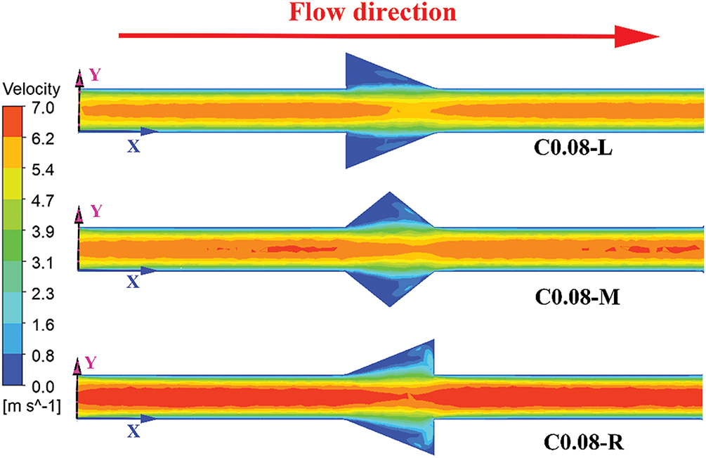
Figure 13: Velocity contours on the z = 0.25 plane for C0.08-L, C0.08-M, and C0.08-R configurations at Re = 519
Fig. 14 presents the comparison of Cf contours and profiles for C0.08-L, C0.08-M, and C0.08-R configurations at Re = 519. It is observed that, the maximum Cf is located on the downstream wall region of the cavity for the mini-channel with different cavity distributions. This phenomenon arises from fluid impingement on the downstream cavity wall. Specifically, in the C0.08-R configuration, the fluid impingement on the downstream wall of the cavity is the strongest, resulting in the largest Cf. Consequently, the average Cf of C0.08-R is the highest, followed by C0.08-M and C0.08-L, respectively.
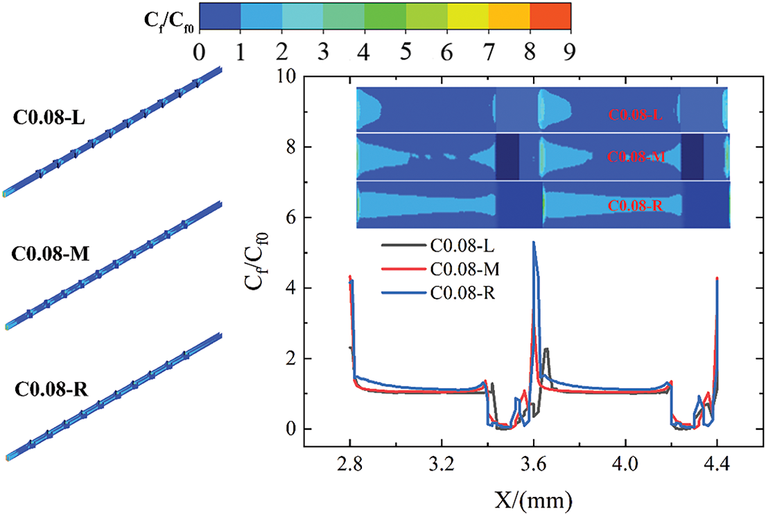
Figure 14: Normalized Cf contours and profiles vs x on the wall for C0.08-R, C0.08-M, and C0.08-L configurations at Re = 519
Fig. 15 shows the influence of cavity distribution on the wall and fluid temperature at the mini-channel outlet. The C0.08-R configuration exhibits the lowest outlet wall temperature and the highest fluid temperature, which is attributed to the heat transfer from the wall to the fluid under equal heat flux conditions. Compared to C0.08-R, the outlet fluid temperature of C0.08-M is slightly lower, while that of C0.08-L is the smallest. Therefore, the C0.08-R configuration is more conducive to heat dissipation.
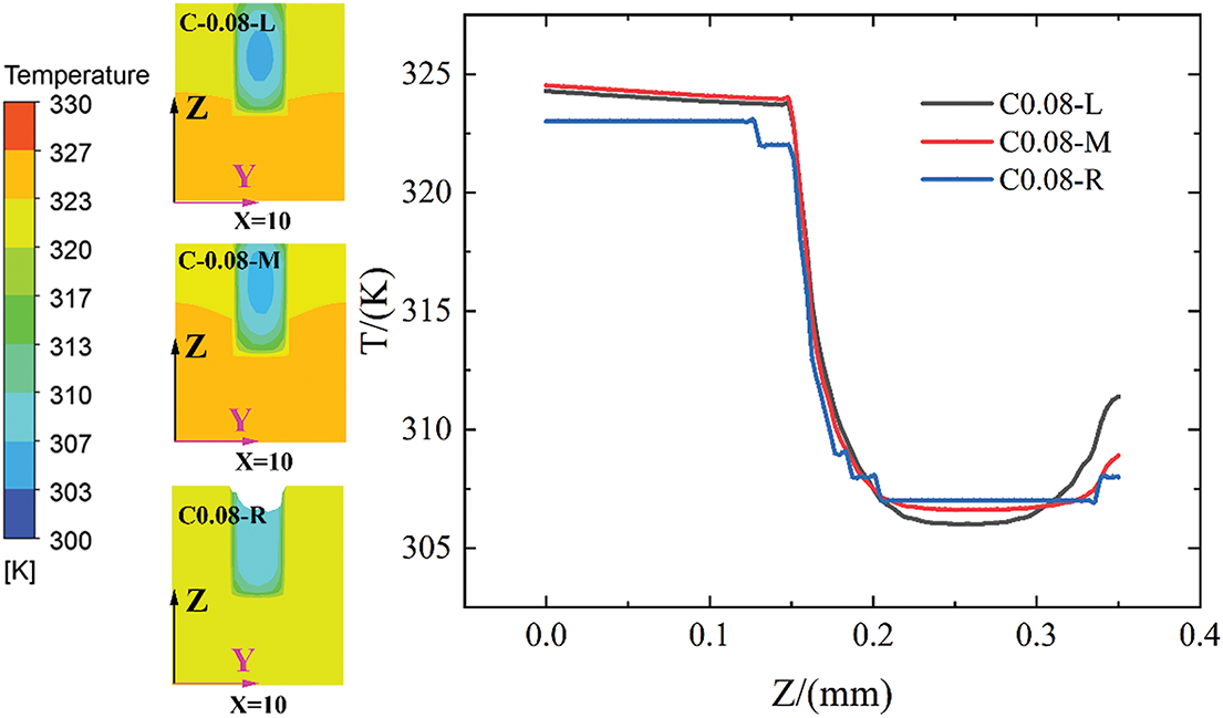
Figure 15: Temperature contours on the x = 10 plane and profiles vs z for C0.08-R, C0.08-M, and C0.08-L configurations at Re = 519
Fig. 16 shows a comparison of the Nu ratio, f ratio, and PEC for C0.08-L, C0.08-M, and C0.08-R configurations. Across all Re conditions, the Nu ratio of C0.08-R is consistently the highest, followed by C0.08-M and C0.08-L. This indicates that C0.08-R exhibits the best heat transfer performance, which is consistent with the analysis results presented in Figs. 14 and 15. Similarly, cavity distribution exerts a certain impact on f ratio, and the f ratio of C0.08-R is the highest, followed by C0.08-L and C0.08-M. However, the percentage difference in the f ratio caused by different cavity distributions is very small. Therefore, under all Re conditions, the PEC values of C0.08-R and C0.08-M are the same and higher than that of C0.08-L. To further investigate the effects of cavity depth and rib height on THP, a cavity distribution similar to that of C0.08-M is selected.
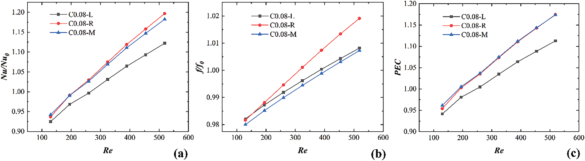
Figure 16: Comparison of Nu ratio, f ratio, and PEC for C0.08-R, C0.08-M, and C0.08-L configurations: (a) Nu/Nu0, (b) f/f0, (c) PEC
Fig. 17 shows the effect of rib height on velocity fluctuations along the flow direction in the mini-channel. Under constant flow rate conditions, ribs with different heights induce periodic velocity fluctuation in the mini-channel. While the rib height does not affect the frequency of velocity fluctuations, it significantly alters their amplitude. Notably, the amplitude of velocity fluctuations in the mini-channel increases with rib height increases. Moreover, compared to rib heights of 0.02 mm and 0.04 mm, the amplitude of velocity fluctuation increases more significantly when the rib height is 0.06 mm. This phenomenon is mainly due to the sharp increase in the blocking effect of ribs on fluid as the rib height increases when the mini-channel height is only 0.02 mm. The larger the amplitude of velocity fluctuations in the mini-channel, the more favorable it is for enhancing fluid mixing between the near wall and central regions.
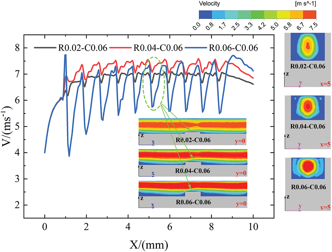
Figure 17: Velocity contours on the y = 0 and x = 5 planes and profiles vs x for R0.02-C0.06, R0.04-C0.06, and R0.06-C0.06 configurations at Re = 519
Fig. 18 displays the comparison of pressure contours along the flow direction in mini-channels with ribs of different heights. An increase in the rib height leads to a sharp increase in the flow-blocking effect, which in turn results in an increase in fluid pressure drop within the mini-channel. As shown in Fig. 18, under the same fluid pressure at the mini-channel outlet, the inlet fluid pressure of R0.06-C0.06 is the highest, followed by R0.04-C0.06 and R0.02-C0.06. Therefore, an increase in the rib height not only amplifies the amplitude of velocity fluctuations but also increases flow resistance, thereby increasing power demand at the inlet of mini-channels.
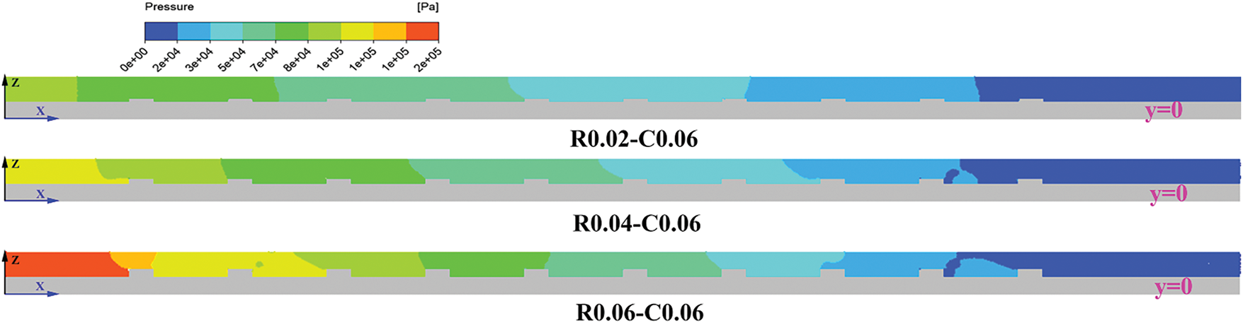
Figure 18: Pressure contours on the y = 0 plane for R0.02-C0.06, R0.04-C0.06 and R0.06-C0.06 configurations at Re = 519
Fig. 19 shows the effect of rib height on Cf and Nu contours at Re = 519. Due to the fluid impingement and flow attachment effects on the wall, significant increases in Cf are observed on the upstream side of the ribs and the downstream side of the cavities in the mini-channel with different rib heights. At the same time, it can be observed that as the rib height increases, both the maximum and average Cf values of the mini-channel is gradually increase. Similarly, the region of the maximum Nu coincide with those of the maximum Cf. As the increase of the rib height, the average Nu gradually increases, indicating that the heat transfer performance of the mini-channel is gradually enhanced.
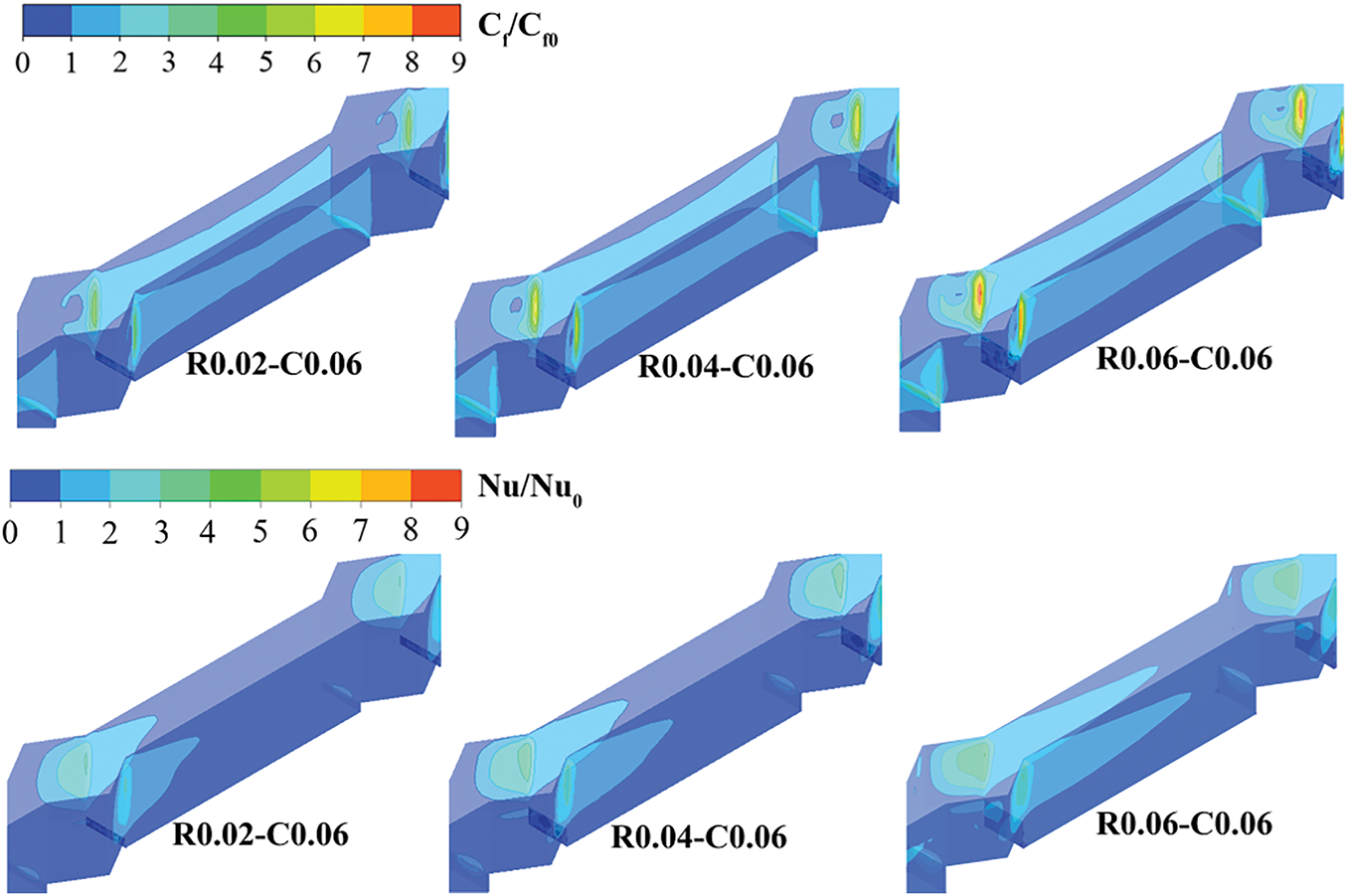
Figure 19: Normalized Cf and Nu contours on the wall for R0.02-C0.06, R0.04-C0.06, and R0.06-C0.06 configurations at Re = 519
Fig. 20 shows a comparison of the Nu ratio, f ratio, and PEC for R0.02-C0.06, R0.04-C0.06, and R0.06-C0.06 configurations. For the Nu ratio, all three configurations exhibit a gradual increasing trend with rising Re, indicates that increasing the Re is beneficial to enhancing the heat transfer effect of the mini-channel. Besides, the higher rib height corresponds to a higher the Nu ratio and the better the heat transfer performance, which confirming the analysis results presented in Fig. 19. The maximum Nu ratio of 1.35 can be obtained for R0.06-C0.06 at Re is 519. Similarly, the f ratio of the mini-channel with different rib heights gradually increases as the rib height and Re increase, further confirming the influence of ribs on fluid flow in the mini-channel. In addition, compared to the increase in f ratio caused by increasing the rib height from 0.02 mm to 0.04 mm, the increase in f ratio is more significant when the rib height increases from 0.04 mm to 0.06 mm, which is consistent with the analysis of velocity fluctuations in Fig. 17. For the PEC, although increasing the rib height can improve the heat transfer performance of the mini-channel, it also significantly increases fluid flow resistance. Consequently, the R0.02-C0.06 configuration achieving the best PEC performance, followed by R0.04-C0.06 and R0.06-C0.06, respectively. A maximum PEC of 1.198 is obtained for the R0.02-C0.06 configuration at a rig height of 0.02 mm and Re = 519.
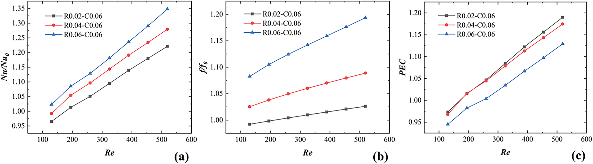
Figure 20: Comparison of Nu ratio, f ratio, and PEC for R0.02-C0.06, R0.04-C0.06, and R0.06-C0.06 configurations: (a) Nu/Nu0, (b) f/f0, (c) PEC
Therefore, when only heat transfer performance is considered and the influence of rib height on pressure drop is neglected, superior heat transfer performance can be achieved by selecting ribs with greater height. However, when both heat transfer performance and pressure drop are considered, a lower rib height yields the optimal overall performance, which is consistent with the research results of Lan et al. [45].
Fig. 21 presents the influence of cavity depth on velocity fluctuations in mini-channels. As shown in Fig. 21, the velocity exhibits periodic fluctuations along the flow direction, but the impact of changes in cavity depth on velocity fluctuation amplitude is very small. This is mainly because, although the increase in the cavity depth causes an expansion of the cross-sectional area of the mini-channel, the fluid velocity within the cavity remains very low, ultimately failing to significantly affect the velocity distribution of the fluid in the central region.
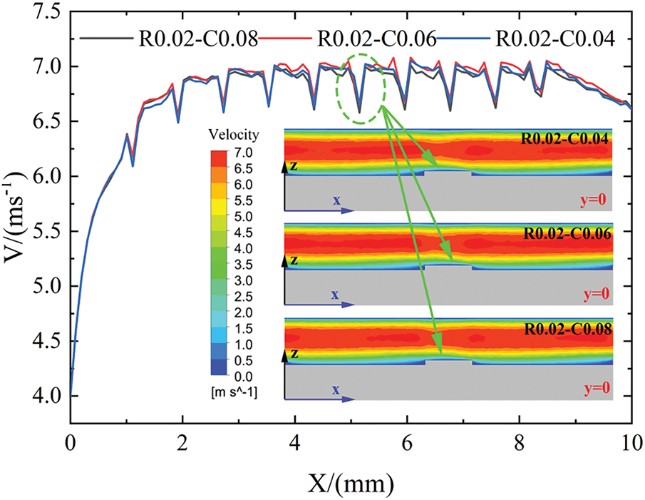
Figure 21: Velocity contours on the y = 0 plane vs x for R0.02-C0.04, R0.02-C0.06, and R0.02-C0.08 configurations at Re = 519
Fig. 22 shows the normalized Cf contours and profiles of R0.02-C0.04, R0.02-C0.06, and R0.02-C0.08 configurations at Re = 519. It can be seen from the contours and profiles that the increase in the cavity depth mainly results in a larger maximum Cf improvement of the mini-channel, which in turn leads to an increase in the average Cf as the cavity depth increases. This phenomenon is attributed to the enhanced flow adhesion effect of the fluid on the downstream side of the cavity as cavity depth increases, which is consistent with the results presented in Figs. 10, 11 and 19. Therefore, as the cavity depth increases, the heat transfer performance of the mini-channel gradually improves due to the thinning of the fluid boundary layer.
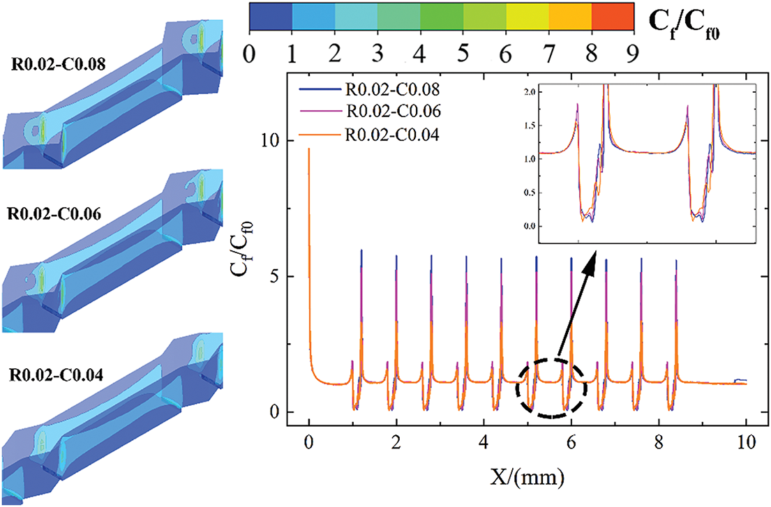
Figure 22: Normalized Cf contours and profiles on the wall for R0.02-C0.04, R0.02-C0.06, and R0.02-C0.08 configurations at Re = 519
Fig. 23 presents the effect of cavity depth on temperature contours and profiles. Corresponding to the effect of cavity depth on average Cf depicted in Fig. 22, an increase in the cavity depth leads to a rise in the average fluid temperature at the mini-channel outlet.
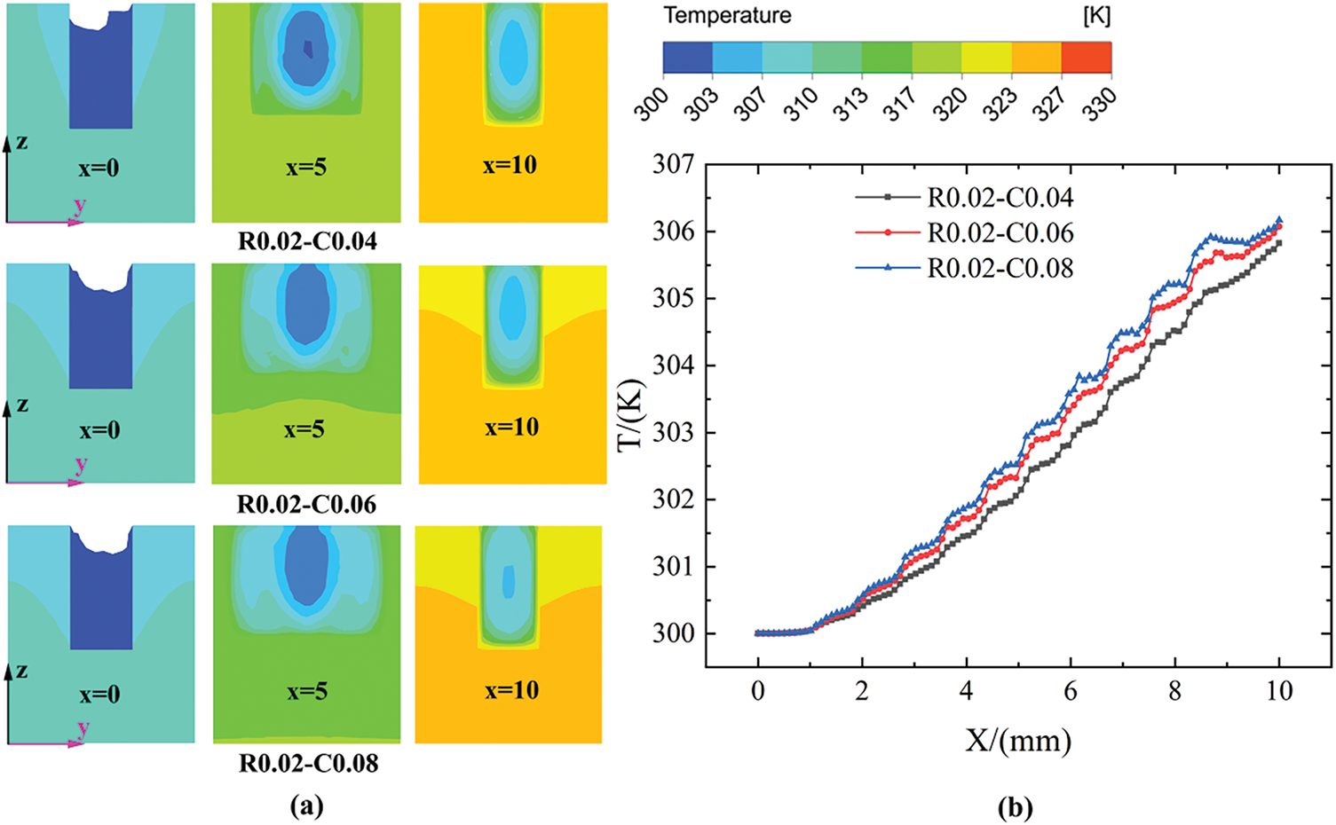
Figure 23: (a) Temperature contours on the x = 0, 10, and 20 planes and (b) profiles versus x for R0.02-C0.04, R0.02-C0.06 and R0.02-C0.08 configurations at Re = 519.
Fig. 24 depicts the comparison of the Nu ratio, f ratio, and PEC under different cavity depths. Notably, the Nu ratio shows a gradually increasing trend with both increasing Re and cavity depth. Specially, the maximum Nu ratio of 1.23 can be obtained at a cavity depth of 0.08 mm and Re = 519. Similarly, an increase in the cavity depth causes an increase in flow resistance in the mini-channel, thus the f ratio increases with the increase of Re and cavity depth, but the increase is limited to within 5%. The comprehensive impact of cavity depth on the Nu ratio and the f ratio reveals that increasing cavity depth exerts a more pronounced influence on Nu amplification than on f amplification. A maximum PEC of 1.198 can be obtained at a cavity depth of 0.08 mm and 0.06 mm as well as Re = 519.
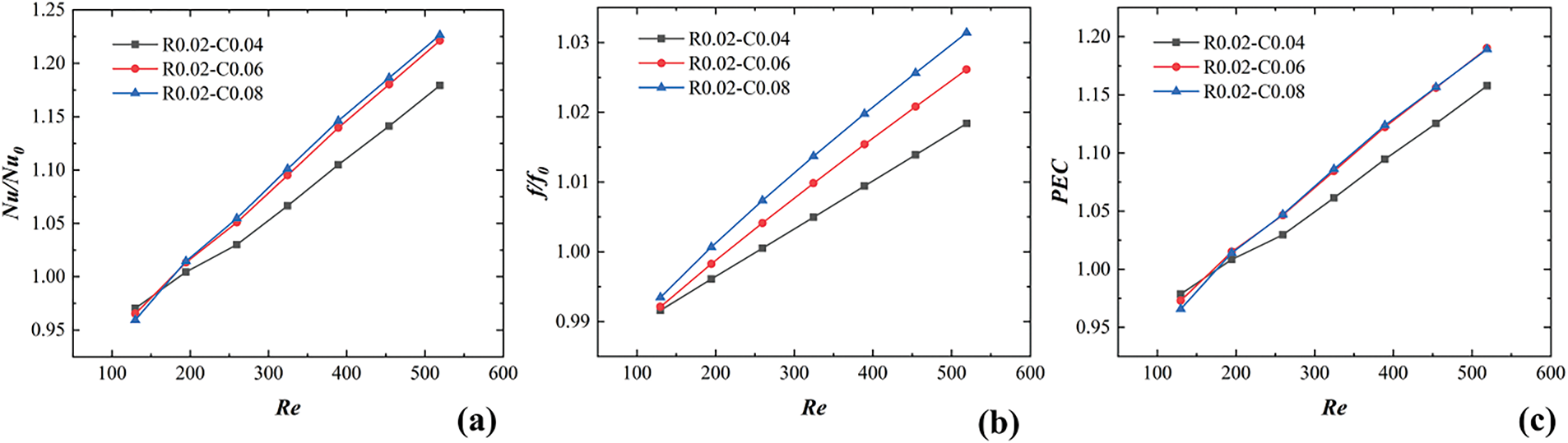
Figure 24: Comparison of Nu ratio, f ratio, and PEC for R0.02-C0.04, R0.02-C0.06 and R0.02-C0.08 configurations: (a) Nu/Nu0, (b) f/f0, (c) PEC
In this work, the advantages of rib-cavity coupling in enhancing the THP of MCHS are systematically investigated, in comparison to the use of ribs or cavities alone. In addition, under rib-cavity coupling conditions, the effects of cavity distributions, cavity depths, and rib heights on the THP are analyzed to optimize appropriate parameters. The key findings are summarized as follows:
(1) Without significantly increasing the fluid pressure drop in the mini-channel, rib-cavity coupling can effectively enhance the convective heat transfer effect between the fluid and the bottom as well as sides wall of MCHS, and improve the THP of MCHS compared to ribs or cavities alone.
(2) Variations in cavity distribution alter the intensity of fluid impingement on the wall, which in turn has different effects on the THP of MCHS. The cavity distribution in C0.08-M configuration yields optimal THP of MCHS.
(3) Increasing the rib height effectively enhances the heat transfer performance of MCHS, but it also leads to a significant increase in pressure drop. Compared to traditional mini-channels, when the rib height is 0.06 mm, the Nu ratio and f ratio increase by 35% and 19%, respectively. However, MCHS can obtain optimal THP when the rib height is the minimum value of 0.02 mm. Therefore, the selection of rib height needs to be determined in conjunction with the requirements for the heat transfer and the pressure drop.
(4) Increasing the cavity depth can improve the heat transfer performance and the pressure drop of MCHS, while also enhancing the THP. The highest PEC of 1.198 is achieved when the cavity depth is 0.08 mm and 0.06 mm, which increases by 19.8% compared to traditional mini-channels.
Acknowledgement: This work was supported by the Sichuan Natural Science Foundation.
Funding Statement: The research was funded by the Sichuan Natural Science Foundation, grant number 2023NSFSC0870.
Author Contributions: The authors confirm contribution to the paper as follows: study conception and design: Wenling Liao; data collection: Shuaimei Lian; analysis and interpretation of results: Shuaimei Lian, Pingping Liu, Wenling Liao; draft manuscript preparation: Shuaimei Lian, Pingping Liu. All authors reviewed the results and approved the final version of the manuscript.
Availability of Data and Materials: The data that support the findings of this study are available from the corresponding author, Wenling Liao, upon reasonable request.
Ethics Approval: Not applicable.
Conflicts of Interest: The authors declare no conflicts of interest to report regarding the present study.
References
1. Lee YJ, Singh PK, Lee PS. Fluid flow and heat transfer investigations on enhanced microchannel heat sink using oblique fins with parametric study. Int J Heat Mass Tran. 2015;81(4):325–36. doi:10.1016/j.ijheatmasstransfer.2014.10.018. [Google Scholar] [CrossRef]
2. Ge Y, He Q, Lin Y, Yuan W, Chen J, Huang S-M. Multi-objective optimization of a mini-channel heat sink with non-uniform fins using genetic algorithm in coupling with CFD models. Appl Therm Eng. 2022;207(5):118127. doi:10.1016/j.applthermaleng.2022.118127. [Google Scholar] [CrossRef]
3. Zhu QF, Chang K, Chen JJ, Zhang XM, Xia HX, Zhang HW, et al. Characteristics of heat transfer and fluid flow in microchannel heat sinks with rectangular grooves and different shaped ribs. Alex Eng J. 2020;59(6):4593–609. doi:10.1016/j.aej.2020.08.014. [Google Scholar] [CrossRef]
4. Duryodhan VS, Singh A, Singh SG, Agrawal A. Convective heat transfer in diverging and converging microchannels. Int J Heat Mass Tran. 2015;80(6):424–38. doi:10.1016/j.ijheatmasstransfer.2014.09.042. [Google Scholar] [CrossRef]
5. Dehghan M, Daneshipour M, Valipour MS, Rafee R, Saedodin S. Enhancing heat transfer in microchannel heat sinks using converging flow passages. Energy Convers Manag. 2015;92(5):244–50. doi:10.1016/j.enconman.2014.12.063. [Google Scholar] [CrossRef]
6. Li P, Zhang D, Xie Y, Xie G. Flow structure and heat transfer of non-Newtonian fluids in microchannel heat sinks with dimples and protrusions. Appl Therm Eng. 2016;94:50–8. doi:10.1016/j.applthermaleng.2015.10.119. [Google Scholar] [CrossRef]
7. Kuppusamy NR, Mohammed HA, Lim CW. Thermal and hydraulic characteristics of nanofluid in a triangular grooved microchannel heat sink (TGMCHS). Appl Math Comput. 2014;246:168–83. doi:10.1016/j.amc.2014.07.087. [Google Scholar] [CrossRef]
8. Li M, Chen X, Ruan X. Investigation of flow structure and heat transfer enhancement in rectangular channels with dimples and protrusions using larger eddy simulation. Int J Therm Sci. 2020;149(3):106207. doi:10.1016/j.ijthermalsci.2019.106207. [Google Scholar] [CrossRef]
9. Li YT, Yuan D, Bian YR, Liang YX, Lu X, Guo FW, et al. Hydrothermal characteristics of inclined grooves with varying numbers and depths in straight, divergent, and convergent minichannels. Appl Therm Eng. 2025;269:125957. doi:10.1016/j.applthermaleng.2025.125957. [Google Scholar] [CrossRef]
10. Chen Y, Fu P, Zhang C, Shi M. Numerical simulation of laminar heat transfer in microchannels with rough surfaces characterized by fractal Cantor structures. Int J Heat Fluid Flow. 2010;31(4):622–9. doi:10.1016/j.ijheatfluidflow.2010.02.017. [Google Scholar] [CrossRef]
11. Wang RJ, Wang JW, Lijin BQ, Zhu ZF. Parameterization investigation on the microchannel heat sink with slant rectangular ribs by numerical simulation. Appl Therm Eng. 2018;133:428–38. doi:10.1016/j.applthermaleng.2018.01.021. [Google Scholar] [CrossRef]
12. Chai L, Wang L, Bai X. Thermohydraulic performance of microchannel heat sinks with triangular ribs on sidewalls-Part 2: average fluid flow and heat transfer characteristics. Int J Heat Mass Tran. 2019;128:634–48. doi:10.1016/j.ijheatmasstransfer.2018.09.027. [Google Scholar] [CrossRef]
13. Alam T, Ansari MM, Kulakrni KS, Haque I, Ali N. Optimization of tapered pin ffns for enhanced heat transfer in microchannel heat sink. Int J Therm Sci. 2025;214:109889. doi:10.1016/j.ijthermalsci.2025.109889. [Google Scholar] [CrossRef]
14. Wang DK, Xue LR, Liu C, Chen HT, Xia CQ, Qian QY, et al. Effects of staggered truncated ribs on thermal-hydraulic performance and entropy generation of microchannel heat sinks. Case Stud Therm Eng. 2025;65(17–18):105597. doi:10.1016/j.csite.2024.105597. [Google Scholar] [CrossRef]
15. Nimmagadda R, Venkatasubbaiah K. Numerical investigation on conjugate heat transfer performance of micro-channel using sphericity based gold and carbon nanoparticles. Heat Tran Eng. 2017;38(1):87–102. doi:10.1080/01457632.2016.1156914. [Google Scholar] [CrossRef]
16. Zargartalebi M, Azaiez J. Heat transfer analysis of nanofluid based microchannel heat sink. Int J Heat Mass Tran. 2018;127(25–26):1233–42. doi:10.1016/j.ijheatmasstransfer.2018.07.152. [Google Scholar] [CrossRef]
17. Souayeh B. Impact of virtual bafes and magnetic nanofuid on thermo‐hydraulic characteristics of sine wave mini channel. J Therm Anal Calorim. 2025;150(5):3845–58. doi:10.1007/s10973-024-13935-6. [Google Scholar] [CrossRef]
18. Zhong S, Zhang C, Fan AW. Numerical study on heat transfer enhancement of laminar ffow in fully wavy wall. A ppl Therm Eng. 2025;266:125782. doi:10.1016/j.applthermaleng.2025.125782. [Google Scholar] [CrossRef]
19. Sajid MU, Abedrabboh O, Bicer Y. Performance evaluation of interrupted and hybrid channel heat sinks for a triple junction high concentrator photovoltaic cell. Int J Thermoffuids. 2025;26:101102. doi:10.1016/j.ijft.2025.101102. [Google Scholar] [CrossRef]
20. Ghadhban FM, Jaffal HM. Numerical investigation on heat transfer and fluid flow in a multi-minichannel heat sink: effect of channel configurations. Res Eng. 2023;17(5):100839. doi:10.1016/j.rineng.2022.100839. [Google Scholar] [CrossRef]
21. Bayer O, Oskouei SB, Aradag S. Investigation of double-layered wavy microchannel heatsinks utilizing porous ribs with artificial neural networks. Int Commun Heat Mass Transf. 2022;134(2):105984. doi:10.1016/j.icheatmasstransfer.2022.105984. [Google Scholar] [CrossRef]
22. Sui Y, Teo CJ, Lee PS, Chew YT, Shu C. Fluid flow and heat transfer in wavy microchannels. Int J Heat Mass Tran. 2010;53:2760–72. doi:10.1016/j.ijheatmasstransfer.2010.02.022. [Google Scholar] [CrossRef]
23. Sui Y, Teo CJ, Lee PS. Direct numerical simulation of fluid flow and heat transfer in periodic wavy channels with rectangular cross-sections. Int J Heat Mass Tran. 2012;55(1-3):73–88. doi:10.1016/j.ijheatmasstransfer.2011.08.041. [Google Scholar] [CrossRef]
24. Sui Y, Teo CJ, Lee PS. An experimental study of flow friction and heat transfer in wavy microchannels with rectangular cross-section. Int J Therm Sci. 2011;50(12):2473–82. doi:10.1016/j.ijthermalsci.2011.06.017. [Google Scholar] [CrossRef]
25. Yuan D, Zhou W, Fu T, Liu CZ. Experimental and numerical investigation of heat and mass transfer in non-uniform wavy microchannels. Int J Therm Sci. 2020;152:106320. doi:10.1016/j.ijthermalsci.2020.106320. [Google Scholar] [CrossRef]
26. Chai L, Xia GD, Wang L, Zhou MZ, Cui ZZ. Heat transfer enhancement in microchannel heat sinks with periodic expansion-constriction cross-sections. Int J Heat Mass Tran. 2013;62:741–51. doi:10.1016/j.ijheatmasstransfer.2013.03.045. [Google Scholar] [CrossRef]
27. Kumar VR, Balasubramanian K, Bhatia K. Numerical investigation of fluid flow and heat transfer characteristics in a novel circular wavy microchannel. Proc Instit Mech Eng Part E J Process Mech Eng. 2019;233(5):954–66. doi:10.1177/0954408918820757. [Google Scholar] [CrossRef]
28. Ahmed HE, Ahmed MI. Optimum thermal design of triangular, trapezoidal, and rectangular grooved microchannel heat sinks. Int Commun Heat Mass. 2015;66:47–57. doi:10.1016/j.icheatmasstransfer.2015.05.009. [Google Scholar] [CrossRef]
29. Xiao H, Liu ZC, Liu W. Turbulent heat transfer enhancement in the mini-channel by enhancing the original flow pattern with v-ribs. Int J Heat Mass Tran. 2020;163(5):120378. doi:10.1016/j.ijheatmasstransfer.2020.120378. [Google Scholar] [CrossRef]
30. Chai L, Xia GD, Wang HS. Parametric study on thermal and hydraulic characteristics of laminar flow in a microchannel heat sink with fan-shaped ribs on sidewalls-Part 1: heat transfer. Int J Heat Mass Tran. 2016;97:1069–80. doi:10.1016/j.ijheatmasstransfer.2016.02.077. [Google Scholar] [CrossRef]
31. Hsieh SS, Hsieh YC, Hsu YC, Huang CF. Low Reynolds numbers convective heat transfer enhancement in roughened microchannels. Int Commun Heat Mass. 2020;112(2):104486. doi:10.1016/j.icheatmasstransfer.2020.104486. [Google Scholar] [CrossRef]
32. Hua JY, Li G, Zhao XB, Li QH, Hu J. Study on the flow resistance performance of fluid cross various shapes of micro-scale pin fin. Appl Therm Eng. 2016;107(5):768–75. doi:10.1016/j.applthermaleng.2016.07.048. [Google Scholar] [CrossRef]
33. Chen Z, Feng ZF, Zhang QY, Zhang X, Guo FW. Effects of regular triangular prisms on thermal and hydraulic characteristics in a minichannel heat sink. Int J Heat Mass Tran. 2022;188(17–18):122583. doi:10.1016/j.ijheatmasstransfer.2022.122583. [Google Scholar] [CrossRef]
34. Zhu QF, Jin YY, Chen JJ, Su RR, Zhu FY, Li HX, et al. Computational study of rib shape and configuration for heat transfer and fluid flow characteristics of microchannel heat sinks with fan-shaped cavities. Appl Therm Eng. 2021;195(6–7):117171. doi:10.1016/j.applthermaleng.2021.117171. [Google Scholar] [CrossRef]
35. Datta A, Sharma V, Sanyal D, Das P. A conjugate heat transfer analysis of performance for rectangular microchannel with trapezoidal cavities and ribs. Int J Therm Sci. 2019;138:425–46. doi:10.1016/j.ijthermalsci.2018.12.020. [Google Scholar] [CrossRef]
36. Li YF, Xia GD, Ma DD, Jia YT, Wang J. Characteristics of laminar flow and heat transfer in a microchannel heat sink with triangular cavities and rectangular ribs. Int J Heat Mass Tran. 2016;98:17–28. doi:10.1016/j.ijheatmasstransfer.2016.03.022. [Google Scholar] [CrossRef]
37. Li YF, Wang ZP, Yang JL, Liu HQ. Thermal and hydraulic characteristics of microchannel heat sinks with cavities and fins based on field synergy and thermodynamic analysis. Appl Therm Eng. 2020;175(5):115348. doi:10.1016/j.applthermaleng.2020.115348. [Google Scholar] [CrossRef]
38. Li YF, Xia GD, Jia YT, Ma DD, Cai B, Wang J. Effect of geometric configuration on the laminar flow and heat transfer in microchannel heat sinks with cavities and fins. Numer Heat Tr A-Appl. 2017;71(5):528–46. doi:10.1080/10407782.2016.1277940. [Google Scholar] [CrossRef]
39. Li YF, Xia GD, Ma DD, Yang JL, Li W. Experimental investigation of flow boiling characteristics in a microchannel with triangular cavities and rectangular fins. Int J Heat Mass Tran. 2020;148:19036. doi:10.1016/j.ijheatmasstransfer.2019.119036. [Google Scholar] [CrossRef]
40. Palm B. Heat transfer in microchannels. Microscale Thermophysical Eng. 2001;5(3):155–75. doi:10.1080/108939501753222850. [Google Scholar] [CrossRef]
41. Zhu QF, Su RR, Xia HX, Zeng JW, Chen JJ. Numerical simulation study of thermal and hydraulic characteristics of laminar ffow in microchannel heat sink with water droplet cavities and different rib columns. Int J Therm Sci. 2022;172(5):107319. doi:10.1016/j.ijthermalsci.2021.107319. [Google Scholar] [CrossRef]
42. Webb RL. Performance evaluation criteria for use of enhanced heat transfer surfaces in heat exchanger design. Int J Heat Mass Tran. 1981;24(4):715–26. doi:10.1016/0017-9310(81)90015-6. [Google Scholar] [CrossRef]
43. Chai L, Xia G, Zhou M, Li J. Numerical simulation of fluid flow and heat transfer in a microchannel heat sink with offset fan-shaped reentrant cavities in the side wall. Int Commun Heat Mass. 2011;38(5):577–84. doi:10.1016/j.icheatmasstransfer.2010.12.037. [Google Scholar] [CrossRef]
44. Zhang DW, Fu LT, Guan J, Shen C, Tang SZ. Investigation on the heat transfer and energy-saving performance of microchannel with cavities and extended surface. Int J Heat Mass Tran. 2022;189(15):122712. doi:10.1016/j.ijheatmasstransfer.2022.122712. [Google Scholar] [CrossRef]
45. Lan YQ, Feng ZF, Huang K, Zhang JX, Hu ZJ. Effects of truncated and offset pin-fins on hydrothermal performance and entropy generation in a rectangular microchannel heat sink with variable fluid properties. Int Commun Heat Mass. 2021;124(17–18):105258. doi:10.1016/j.icheatmasstransfer.2021.105258. [Google Scholar] [CrossRef]
Cite This Article
 Copyright © 2025 The Author(s). Published by Tech Science Press.
This work is licensed under a Creative Commons Attribution 4.0 International License , which permits unrestricted use, distribution, and reproduction in any medium, provided the original work is properly cited.
 Downloads
 Citation Tools