
 Submit a Paper
 Propose a Special lssue
 Open Access
ARTICLE

Analysis of Air Conditioning Unit Performance Due to Variations in Water Cooling Temperature Using an Extra Cooling Water Loop
1 Engineering Technical College of Mosul, Northern Technical University, Cultural Group Street, Mosul, 41002, Iraq
2 College of Mechanical Engineering, University of Zakho, Kurdistan Region, Zakho, 42002, Iraq
3 College of Technical Engineering, Duhok Polytechnic University, Duhok, 42001, Iraq
* Corresponding Author: Omar Rafae Alomar. Email:
Frontiers in Heat and Mass Transfer 2025, 23(6), 2001-2024. https://doi.org/10.32604/fhmt.2025.066997
Received 23 April 2025; Accepted 12 September 2025; Issue published 31 December 2025
 View Full Text
 Download PDF
Abstract
The energy consumption of a Split air conditioning unit (ACU) inside a building is extremely large, and efforts to decrease this issue are ongoing. The current work aims to experimentally investigate the thermal performance of ACU using an external cooling-water loop for pre-cooling the condenser to improve the efficiency and to reduce energy consumption by reducing refrigerant temperature before entering the condenser, thereby reducing the coefficient of performance. The experiments are performed on ACU with and without using an external cooling-water loop under different climate conditions. By using the experimental data, the systems’ performances for both cases are evaluated based on the energy, exergy, and pressure drop analysis. Effects of several parameters, e.g., ambient temperature, inlet water temperature, and water volume flow rate, on the energy and exergy performances of ACU systems are presented for the purpose of comparison. The outcomes display that the use of an external cooling water loop system has a significant impact on the system performance as compared to conventional ACU. The results display that the addition of an external cooling-water loop leads to a reduction in the compressor power consumption and to an increase in the coefficient of performance (COP) as compared to a normal ACU. The maximum reduction in compressor power consumption is obtained equal 37% at Tw = 15°C and 11 L/min, whereas the maximum enhancement in COP is obtained equal 21.5% at Tw = 30°C, 11 L/min, and Tamb = 45°C. The modified model shows an increase in exergy efficiency with the maximum enhancement of about 17% at Tw = 30°C and 15.8 L/min. The use of an external cooling water loop leads to a reduction in the irreversibility process of the compressor, evaporator and expansion valve and to an increase in the condenser losses. The outcomes show that the pressure drop is reduced by using a cooling water loop as compared to a normal ACU, where the reduction becomes more evident with a reduction in water volume flow rate and inlet temperature. Finally, the present study reveals that the use of an external cooling water loop system leads to an improvement in the performance of ACUs.Keywords
The increased need for air conditioning and refrigeration systems results in high energy consumption. Different methods to implement new technologies are used to reduce the consumption of the air conditioning system energy [1]. In the world, it is estimated that the number of Air Conditioning Units (ACU) reaches about 2 billion in the present. The International Energy Agency (IEA) forecasts the ACU will increase to 5.5 billion units by 2050. The building air conditioning systems consume more than 20% of total energy consumption [2]. The ACU, which uses a vapor compression refrigeration cycle (VCC), has evolved into one of the most essential requirements for a comfortable human life [3]. The split ACU type is one of the most energy-consuming devices in today’s society [4]. The air-cooled condensers are used for heat rejection during the vapor compression refrigeration cycle of ACU systems. When air temperatures around the air-cooled condenser are raised, the compressor needs to operate with a high-pressure ratio, which leads to poor performance. The temperature of 50°C or more than this value is the tipping point for problems with air conditioners in many Middle East countries [5–7]. The improvement of the efficiency of air conditioning units is one of the primary projects aimed at conserving energy and reducing CO2 emissions [8–10].
Ardita and Subagia [11] experimentally studied the use of condensate water to cool an air-cooled condenser in a small window-type air conditioner using R407C as refrigerant to improve the energy performance of the air conditioning system. The results displayed that a rise in ambient air temperature has an effect on the system’s efficiency and COP. Kamlesh et al. [12] examined the cellulose media pad in an air-cooled refrigeration system’s cold air condenser (evaporative cooler). The findings show that when an evaporative cooler is used, the power consumption is reduced. Naphon [13] studied experimentally the heat pipe for cooling air before entering the condenser. The highest COP and energy efficiency rating EER is achieved by an air conditioning unit using three rows of heat pipes with an increase of 6.4%, 17.5% respectively, as compared with those of a traditional air-conditioning system. Siricharoenpanich et al. [14] improved the thermal efficiency of an air conditioning system using a cooling water loop to cool the refrigerant before entering the condenser unit. The results showed the highest COP with a value of 31.02% as compared to those of the usual reference system. The COP decreases with increasing ambient temperature and increases with increasing water mass flow rate. Shah et al. [15] studied experimentally the employment of the evaporative cooling pad with different types and thicknesses in a 0.8 TR split air conditioner charged with R22. The findings show that the increased percentages are 13.8% in overall COP, 9.5% reduction in power consumption and 5.1% increase in cooling capacity. Jassim [16] experimentally investigated the performance of an air-cooled split air conditioner with evaporative water mist pre-cooling under a hot and dry climate. The findings indicate that the capacity of cooling would be improved. While consumed power would be reduced, improving the EER or energy ratio by 47 percent under the same ambient temperature range. Alhamdo et al. [17] experimentally studied the energy and economic modifications using sprayed water on the condenser with a wet Pad, which is placed at the inlet of the condenser. The performance of a Water-Refrigerant evaporator has been compared to that of an original air-refrigerant evaporator. The spray water (SW) modification for improving condenser performance was found to be the most effective method for increasing the COP. Sumeru et al. [18] investigated the effects of subcooling on system performance for a residential air conditioner with R410A as the working fluid and a compressor capacity of 0.75 kW. The results showed that the use of condensate water reduced the refrigerant temperature in the condenser outlet by 2.7°C, which leads to an increase in the COP with a value of 16.4%. The discharge compressor’s temperature is reduced by 7.6% and 5.9% reduction in the air conditioning system’s power consumption. Alklaibi [19] presented and discussed the various options to perform the reheat process by combining a loop heat pipe with the air conditioning system. The findings displayed that the Loop Heat Pipe (LHP) can be used instead of a heating element to improve the COP of small air-conditioning units. The employment of the loop heat pipe under low room sensible heat factor conditions increases the COP by approximately a factor of 2.1.
Other previous studies have used the exergy analysis to investigate the ACU performance. For example, Bolaji [20] investigated the performance of a domestic refrigerator using R134a and R152a based on the exergy analysis and the results are compared with the performance of the system operated using R12 as a refrigerant. The outcomes displayed that the reduction in COP for R152a and R134a, as compared to R12, is 1.4% and 18.2%, respectively. The maximum average exergy efficiency of the system that used R152a is found to be equal to 41.5%. Kılıc [21] studied the exergy performance of two two-stage and intercooler vapor compression refrigeration cycles using the refrigerants R507, R407c and R404a as refrigerants. The results displayed that the COP of the system and exergy efficiency for the system that used R407c are enhanced as compared to other refrigerants. Ceviz et al. [22] investigated the impacts of source on the system performance of a refrigerant compressor using R134a as refrigerant. The experimental outcomes displayed that the value of COP of the heat pump is increased by 172% when the source temperature rises from 6°C to 34°C. This progress is obtained as 17% for low pressure and 34% for high pressure when the source temperature is raised from 6°C to 34°C. Afshari et al. [23] investigated the effects of various parameters on heat pump performance using a laboratory setup. Parameters include refrigerant type, charge amount, compressor oil viscosity, compressor cooling fan, secondary fluid temperature and flow rate. The results showed that the refrigerant charge amount significantly affects COP. The temperature of the heat source increased system performance by over 11%, and selecting a low viscosity compressor oil increased performance by 18%. The cooling fan also improved performance by over 6%. Afshari et al. [24] investigated the conversion of a laboratory heat pump into a refrigeration unit to evaluate efficiency, power consumption, pressure and temperature variations, and optimal charge amount using refrigerant R-407C. The study focuses on the impact of refrigerant charge amount on performance, operating cost, and environmental concerns in both heat pump and refrigeration systems. Results show that the COP value of the system is lower than that of the heat pump unit.
Kasni et al. [25] experimentally studied the use of condensate produced by the evaporator inside the Air Heating Unit (AHU) for cooling the compressor discharge line. The results indicated that the COP of the system is increased by 9.8%, the input power is reduced by 3.8% and the cooling capacity is increased by 5.7%. Kasni et al. [26] investigated the impact of condensate water as the compressor-discharge cooler on the effectiveness of the A/C system using R32. The outcomes show that a larger heat exchanger generated a larger degree of sub-cooling and hence, the increase in degree of sub-cooling produces enhancements in cooling capacity and COP of the A/C system. Aziz et al. [27] investigated the impact of ambient temperature and humidity on the performance of vapor compression air conditioning systems. It found that as the temperature rises from 22°C to 40°C, the compressor temperature increases, resulting in an increase in power consumption. Aziz et al. [28] studied the use of condensate in split air conditioning systems to improve performance. By integrating a direct evaporative cooling system with condensate, the air temperature is reduced before entering the condenser. The research compares the performance of split air conditioning systems with and without direct evaporative cooling. Results show that using direct evaporative cooling reduces compressor discharge pressure, resulting in a 4.7% drop in power consumption for the air conditioner without a cooling load and a 7% decrease for the air conditioner with a 2000 W cooling load. The cooling effect and coefficient of performance (COP) also improve when compressor power decreases. Thus, using direct evaporative cooling with condensate can enhance system efficiency and protect the environment. Zeinal Heris et al. [29] studied the impacts of adding carboxyl-functionalized multi-wall carbon nanotubes and hydroxyl-functionalized to water on the thermal performance of corrugated PHEX. The findings indicated that the highest enhancement values of convective heat transfer coefficient are equal to 35.81% and 42.56% when using MWCNTs-OH/water and MWCNTs-COOH/water, respectively. On the other hand, the highest enhancement in the exergy efficiency is equal 28% when using 0.06 wt% MWCNTs-COOH/water as compared to pure water.
A full check in the open literature investigations reveals that most of the studies dealing with ACU systems are numerically investigated considering the vapor compression refrigeration cycle to improve their performances by modifying the system through using, e.g., indirect evaporator cooler, evaporative water, porous medium, nanofluids and heat pipes. There are other previous studies that deal with improving the performance of ACU by increasing the temperature of the inlet refrigerant before entering the condenser. While most of these studies are focused on the performance of the ACU system, there is a lack of experimental studies related to the energy and exergy analysis. Moreover, the survey on the literature reveals that there are no experimental investigations that deal with improving the performance of the ACU system by using an external cooling water loop to pre-cool the condenser under a wide range of operating conditions (e.g., ambient air temperature around the condenser, inlet water temperature and water volume flow rate) based on the energy and exergy analysis. The employed of external Cooling-Water Loop operates by circulating water from a cooling tower or evaporative cooler around the condenser, absorbing heat from the coils before the refrigerant reaches full condensation, thereby reducing compressor effort and improving system performance. To have a better insight into the actions of using a cooling water loop heat exchanger on the performance of the ACU system, an experimental investigation is required. So, the main target of this investigation is to experimentally perform and compare the performance of a split air conditioning unit without and with modifying the system through using an external cooling water loop heat exchanger to pre-cool the condenser under different climate conditions. By using the experimental data, the performances for both cases are evaluated based on the energy and exergy analysis. The results of the evaporator cooling load, compressor power consumption, COP, exergy efficiency, and pressure drop of the system are presented and discussed with and without using a cooling water loop for a wide tested parameters (ambient temperatures around the condenser, inlet water temperature and water volume flow rate). The research empirically assesses the efficacy of water-based pre-cooling, offering empirical performance data. This improvement is particularly relevant in hot and arid environments where high ambient temperatures diminish traditional air-cooled condensers’ effectiveness.
2.1 Weather Conditions of Zakho City
Zakho city is a border city in northern Iraq with coordinates of 37.15° north and 42.67° east. In general, the magnificent overall solar insolation level in northern Iraq reaches 1050 W/m2. The ambient temperature varies from −3.4°C to 47°C. The maximum range of temperature is found during the summer season. The mean wind speed is less than 2 m/s. On the other hand, the humidity ranges between 50% and 60% [30].
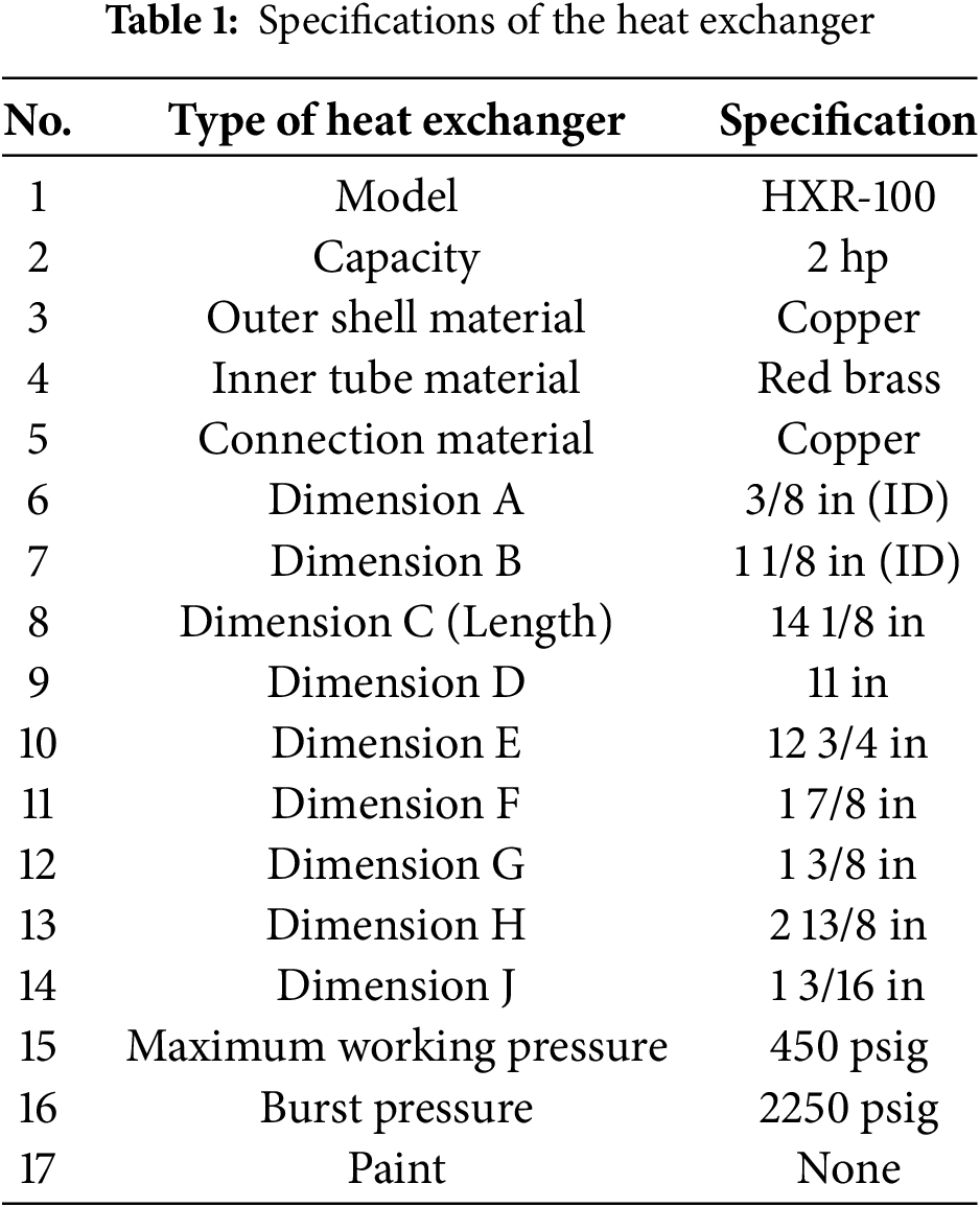
The test rig model, which consists of a split ACU and its accessories, is designed and installed inside a room in the laboratory at Zakho Technical Institute, Duhok Polytechnic University. The tested room has dimensions of 4 m × 3 m × 2.9 m. The room has two exterior walls, whereas the roof and other walls are interior walls inside the lab. Fig. 1 displays a schematic diagram of the main experimental apparatus, which includes the main parts of the ACU of 1 t refrigeration capacity (3.52 kW), where the refrigerant R22 is used as a working fluid. The main components of ACU are: rotary compressor, air-cooled condenser finned tube, expansion valve and compact finned tube air-cooled evaporator. The split ACU uses the refrigerant R22 as a working fluid. The cooling load of the room is estimated manually to install the split ACU inside the room, where the internal loads include 2 persons, lights and other miscellaneous loads. The real photo of test rig model along with its description is shown in Fig. 2. To improve the performance of ACU, a shell and coil tube heat exchanger (HXR-100) is used for experimental study as the cooling water loop and installed at discharge line which connects between the compressor and the air condenser to transfer heat from the liquid refrigerant line to the cold water. The specifications of the heat exchanger are shown in Fig. 3 and Table 1. As shown in Fig. 3, the superheated vapor refrigerant flows into the heat exchanger tube through the inner tube, whereas the cooling water flows through the outer tube. This type of heat exchanger provides several benefits, including: evaporation of any excess liquid in the suction line before it enters the compressor, sub-cooling any excess vapor in the liquid line before it enters the expansion valve, and increasing the vapor temperature to prevent the formation of ice in the suction line.

Figure 1: Schematic diagram of the experimental apparatus
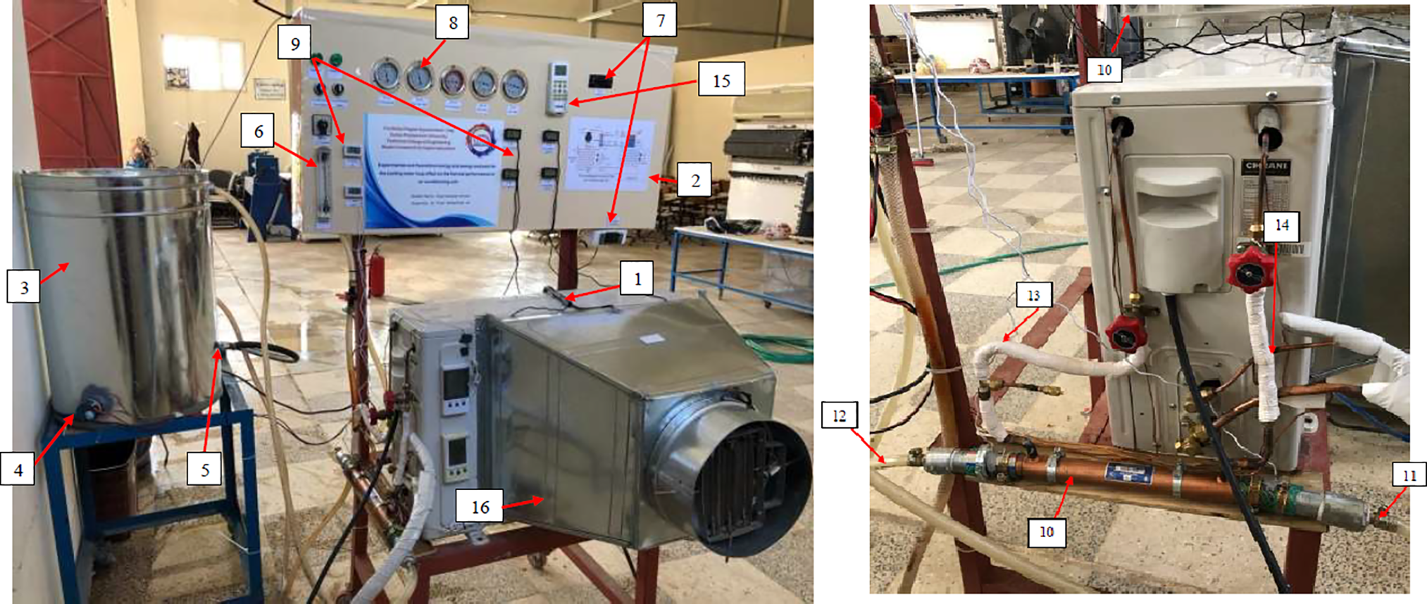
Figure 2: Real photo of test rig model (1. AC outdoor unit, 2. Controlling board, 3. Water tank, 4. Water heater, 5. Water pump, 6. Water flow meter (L/min), 7. Heater’s thermostat, 8. Pressure gauge of refrigerant, 9. Thermometers, 10. Refrigeration heat exchanger, 11. Inlet water, 12. Outlet water, 13. Inlet Ref, 14. Outlet Ref, 15. AC remote control and 16. Air heater)
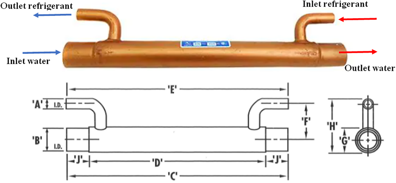
Figure 3: Schematic diagram of the refrigerant heat exchanger
In the present investigation, the ambient temperature, inlet and outlet water temperatures and the inlet and outlet air condenser temperatures are controlled using measurement instruments, where their locations are shown in Fig. 2. These temperatures are measured using the thermocouples with an accuracy of ±1°C. The pressure of the refrigerant at the inlet and the outlet of the compressor, outlet of the refrigeration heat exchanger, inlet and outlet of the expansion valve are measured using analog bourdon gages as shown in Fig. 1. The volumetric water flow rate, which enters the heat exchanger, is measured with a water flow meter (rotameter). The experimental tests were performed during October 2021.
2.3 Experimental Procedure and Operating Conditions
The experiments have been carried out over a 10-h period (from 8 a.m. to 6 p.m.) and the measurements are recorded every 10 min when the operation of ACU becomes under steady-state conditions. The readings of the ambient temperature surrounding the condenser are (30°C, 35°C, 40°C and 45°C). The range of the inlet water temperature, which flows into the heat exchanger, is between 15°C and 30°C. The range of water flow rate, which flows inside the heat exchanger, is between 9 and 15.8 L/min. The measurements of refrigerant temperature and pressure are recorded under steady state with the following conditions: surrounding air temperature around the condenser at 30°C, inlet water temperature at 15°C and water flow rate of 9 L/min. Then the same measurements are recorded when the volume flow rate is changed to 11 L/min with constant outlet ambient air condenser temperature and inlet water temperature. The readings are measured for all ambient air condenser temperature, inlet water temperature and water volume flow rate.
It is important to apply the uncertainty analysis in the present work due to instrument errors, measurement variance and calibration errors. In the current work, this method is applied based on the exact characteristics of the uncertainties in the initial experimental measurements as presented by Holman [31]. The uncertainties of the evaluated and measured experimental parameters of the system are obtained as follows [31]:
where
Thus, the final uncertainty value of COP can be obtained as follows:
The uncertainty value of the enthalpy h can be calculated as follows:
where Δp and ΔT are the uncertainties in pressure and temperature measurements, respectively. Table 2 displays the uncertainty values of the measured variables, where the total uncertainty value of COP is obtained as equal to ±4%.

3 Evaluation of the System Performance
The performances of the system with and without using a cooling water system are evaluated based on the energy and exergy analysis for a simple vapor compression refrigeration cycle (VCRC) using R22 as refrigerant. As mentioned before, two cases are presented, where the first case represents the conventional Split Air Conditioning Unit (ACU), whereas the second case represents the modifying system by using a cooling water loop heat exchanger to pre-cool the refrigerant before inlet into the condenser of the ACU. The energy and exergy analysis is presented based on the following assumptions: steady, one-dimensional, neglect kinetic and potential energies, neglect heat losses, neglect pressure drop and neglect the power of the pump.
Based on the energy analysis, the performance of ACU is evaluated along with its main components (evaporator, compressor, condenser, and expansion valve). The refrigerant mass flow rate can be calculated according to the variety of refrigerant properties. In the present study, two different cases are used: a conventional vapor compression refrigeration cycle and a vapor compression refrigeration cycle with water water-cooled loop. The work input is evaluated as [14]:
where
where h2 and h3 display the enthalpies of the refrigerant at the inlet and outlet of the condenser, respectively. The heat transfer rate in the coiled and shell tubes heat exchanger can be calculated as [14]:
where
where h1 and h4 display the enthalpies of the refrigerant at the inlet and outlet of the evaporator, respectively.
The performance coefficient (COP) without and with adding a heat exchanger can be calculated as follows [14]:
where
In order to get more accurate solutions, the exergy analysis can be used instead of energy analysis. The exergy analysis is performed based on the 2nd law of thermodynamics, and hence this analysis deals with the exergy losses, where the irreversibility process is considered due to the losses in the reversible work and useful work difference when the state is varied [32]. In general, the exergy balance can be expressed as [32]:
where Exin − Exout represents the net exergy transfer rate by heat, work and mass. The exergy efficiency for each steady-flow device can be written as
The exergy destruction of fluid circulating in the refrigeration system components can be defined as [33–35]:
● For compressor:
● For condenser:
● For heat exchanger
● For capillary tube:
● For evaporator:
where
The present work includes an experimental investigation on the split ACU system to demonstrate the effects of adding a cooling water loop in the condenser on the system performance and compare the predicted solutions with those obtained using a typical split ACU system. The solutions are obtained based on the energy and exergy analysis under a wide range of inlet water temperature (Tw), ambient temperature (Tamb) and water volume flow rate. The condensers of the split unit, without and with using a water loop, are tested with the following conditions:
• Ambient temperature (Tamb): 30°C, 35°C, 40°C and 45°C
• Inlet water temperature of heat exchanger (Tw): 15°C, 19°C, 24°C and 30°C
• Water volume flow rates: 9, 11, 14 and 15.8 L/min
For the purpose of comparison, all tested cases with and without adding a cooling water loop are performed under the same operating conditions (i.e., ambient temperature, inlet water temperature and water volume flow rates). Fig. 4 displays the comparison between the conventional ACU system unit and the modified system, which uses of cooling water heat exchanger. The comparison between both systems is presented on the P-h diagram, where the system that operated with a cooling water loop is referred by (1′, 2′, 3′ and 4′), whereas the conventional system is referred by (1, 2, 3 and 4). It can be noticed that the evaporator cooling capacity and the compressor power consumption are reduced by using a water loop, whereas the COP of the system is raised as compared to the conventional system (without using a water loop). Moreover, the superheating and sub-cooling degrees are increased. The details solutions from the current investigations are presented in Figs. 5–13 for both with and without using a cooling water loop heat exchanger under the impact of various parameters listed above. The solutions include the evaporator capacity Qevap, power consumption, coefficient of performance, exergy destruction, exergy efficiency and pressure drop.
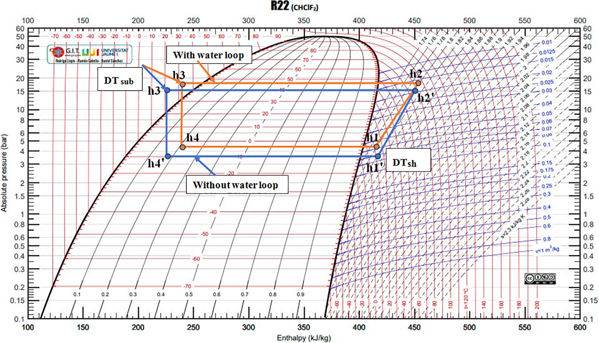
Figure 4: P-h, diagram of air conditioning system without and with adding cooling water loop system at Tamb = 30°C, Vol = 9 L/min and inlet Tw = 19°C

Figure 5: Effects of Tamb on (a) Superheating and (b) Sub-cooling for various inlet Tw at inlet water flowrate 11 L/min
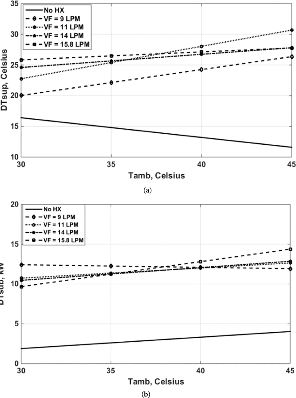
Figure 6: Effects of Tamb on (a) Superheating and (b) Sub-cooling for various volume flow rates at inlet Tw = 19°C

Figure 7: Effects of Tamb on energy performance for various volume flow rates at inlet Tw = 19°C. (a) cooling capacity Qevap, (b) compressor power and (c) COP

Figure 8: Effects of Tamb on energy performance for various inlet Tw at inlet water flowrate 11 L/min. (a) cooling capacity Qevap, (b) compressor power and (c) COP
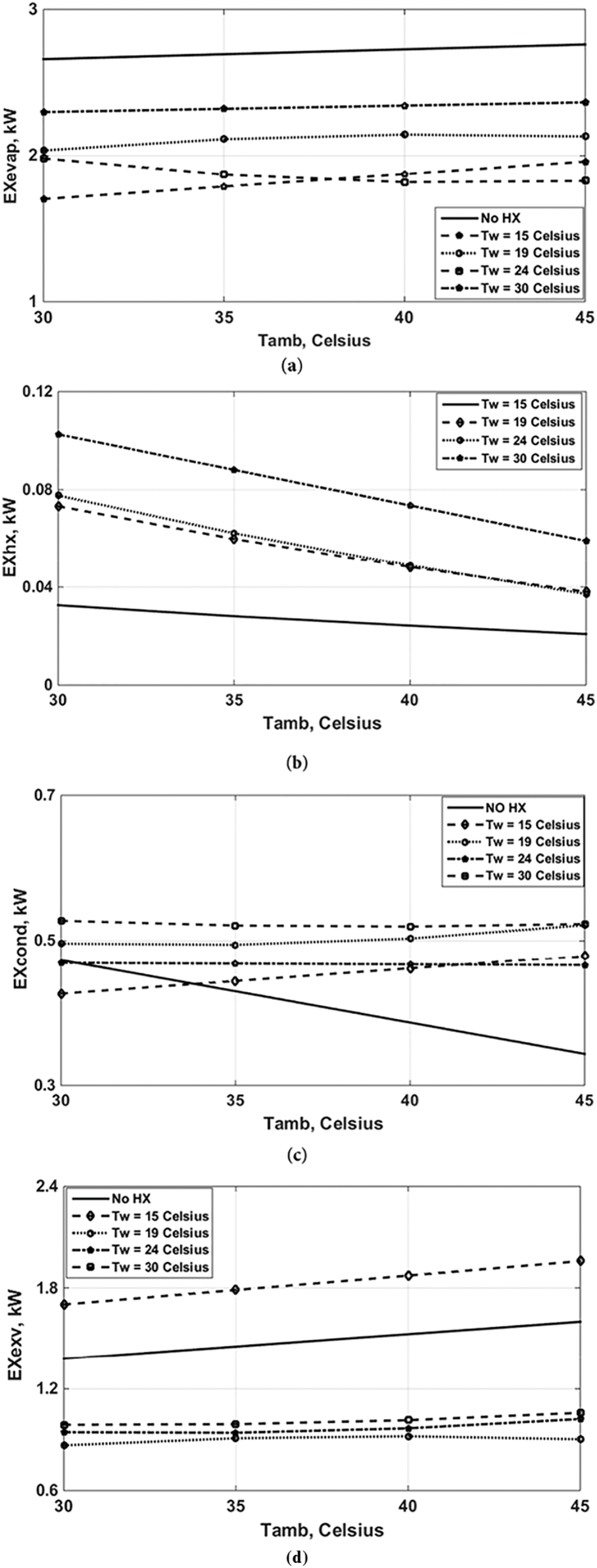
Figure 9: Effects of Tamb on exergy destruction for various inlet Tw at volume flow rate 11 L/min. (a) evaporator, (b) heat exchanger, (c) condenser and (d) expansion valve
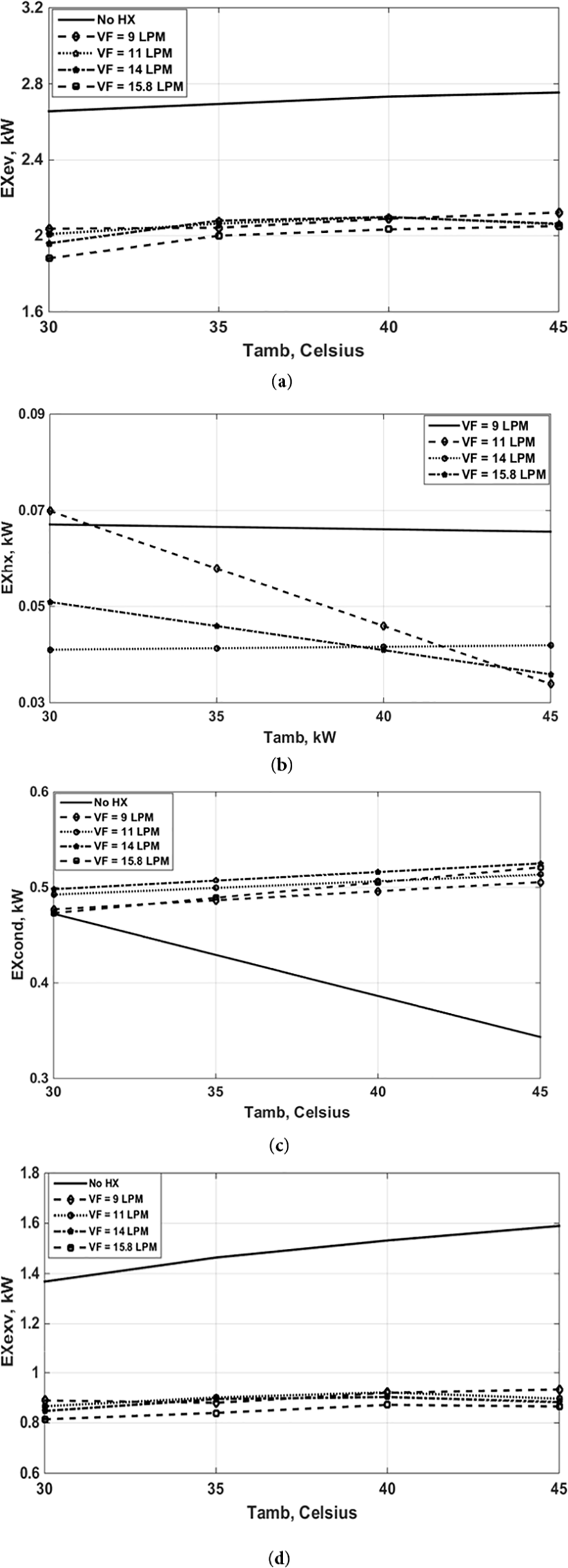
Figure 10: Effects of Tamb on exergy destruction for various water volume flow rates at Tw = 19°C. (a) evaporator, (b) heat exchanger, (c) condenser and (d) expansion valve
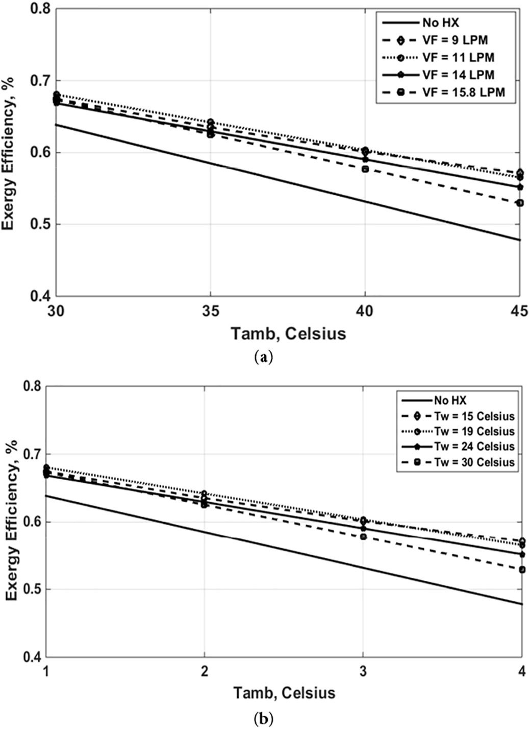
Figure 11: Effects of Tamb on exergy efficiency for (a) various water volume flow rates at Tw = 19°C and (b) various Tw at water volume flow rate 11 L/min
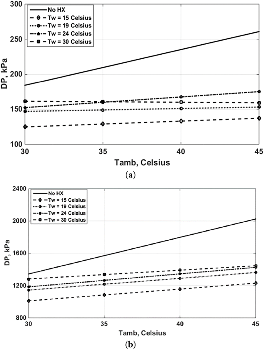
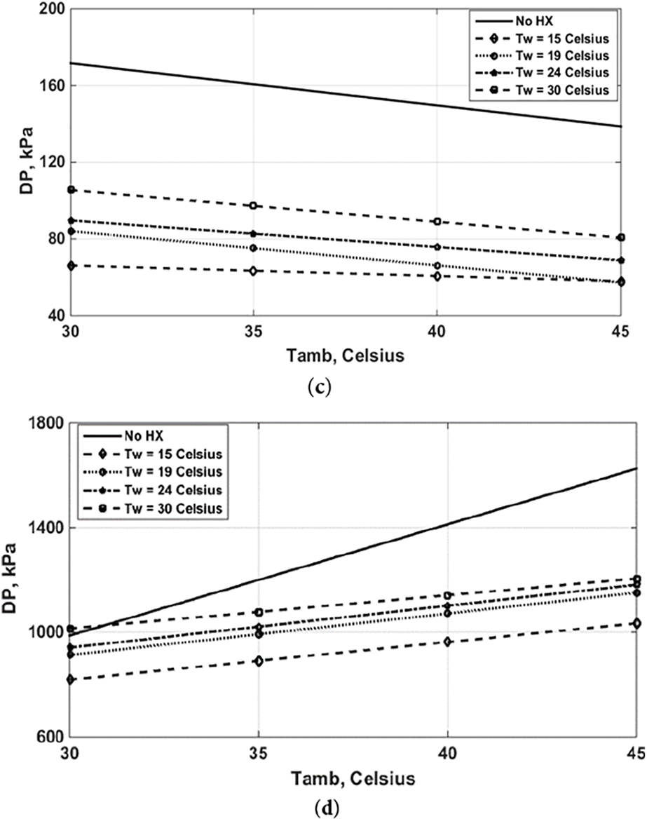
Figure 12: Effects of Tamb on pressure drop for various Tw at water volume flow rate 11 L/min. (a) evaporator, (b) heat exchanger, (c) condenser and (d) expansion valve
Figure 13: Effects of Tamb on pressure drop for various water volume flow rates at Tw = 19°C. (a) evaporator, (b) heat exchanger, (c) condenser and (d) expansion valve
4.1 Solution of Energy Performance
Figs. 5 and 6 display the effects of Tamb on the superheating and sub-cooling degrees for various inlet Tw and water volume flow rates. For the no cooling water loop case, the findings show that the superheating degree is decreased with increasing Tamb, whereas the sub-cooling degree is slightly increased with rising Tamb. Superheating for a water loop occurs at the evaporator outlet when the refrigerant is elevated beyond its saturation temperature. As the temperature difference decreases, heat absorption decreases. Elevated Tamb raises condenser pressure, affecting thermal absorption. Sub-cooling occurs at the condenser outlet, where the refrigerant is cooled below its saturation temperature. Elevated temperature gradient enhances heat rejection, resulting in modest sub-cooling. The utilization of the cooling water loop leads to an increase in the superheating and sub-cooling degrees when the inlet water temperature and flow rate are raised. The findings in Fig. 5 display that the decrease in Tw leads to a rise in the superheating degree except for the case when Tw = 30°C, where this case is equal to Tamb = 30°C. The sub-cooling degree increases with the rise in Tw. On the other hand, the findings in Fig. 6 display the effects of volume flow rate on the superheating and sub-cooling degrees, where the solutions indicate that the superheating degree is raised as the water heat exchanger is used. The sub-cooling degree is also increased when using a cooling water heat exchanger for all tested volume flow rate values. Superheating, for a water loop, in a condenser increases with inlet water temperature and flow rate. The cooling water loop affects the condenser’s functioning, with elevated inlet water temperature reducing heat dissipation and increasing condenser pressure. An increase in condenser pressure raises the refrigerant’s saturation temperature, allowing it to absorb more heat in the evaporator, leading to increased superheating. An increased water flow rate boosts thermal transfer, increasing system efficiency and potentially causing increased superheating. Elevated inlet water temperature and flow rate also increase sub-cooling, reducing heat rejection in the condenser and enhancing sub-cooling.
Fig. 7 displays the actions of Tamb on the evaporator cooling capacity, compressor power and COP at Tw = 19°C and various water flow rates. For the no cooling water loop case, the findings show that the cooling capacity is decreased with an increase in Tamb. Also, the value of Qevap is reduced when the cooling water loop is used. For a water flow rate of 11 L/min, the solutions indicated that the cooling capacity is decreased with rising Tamb. However, its trends are similar to the solutions of the system that operated without using the water loop case. When the value of volume flow rate is 9 L/min, the value of Qevap reaches the same value of Qevap at Tamb = 45°C. For volume flow rate 14 L/min, the reduction in Qevap with rising in Tamb becomes less and reaches the same value of Qevap as the no water case, while the Qevap is constant at VF = 15.8 LPM, which reaches to same value of Qevap for the case without using the water loop. The solutions in Fig. 7 observed that the consumed power of the compressor is reduced when the cooling water loop is used, with a reduction percentage of about 26% at Tamb = 30°C and 17% at Tamb = 45°C. The enhancement is considerable, as previous studies reveal significant reductions in compressor power consumption, including a minimum decrease of 4.7% attained through direct evaporative cooling with condensate, a maximum reduction of 16% via an advanced evaporative cooling system, and additional noteworthy reductions of 5.9% utilizing condensate water, 9.5% with a cellulose cooling pad, and 47% through evaporative mist pre-cooling. For the system that operated without using a cooling water loop, the solutions show that the COP value is decreased with rising Tamb. Moreover, the findings indicated that the value of COP is enhanced when using a water-cooling loop. The highest enhancement in COP value is obtained for volume flow rate equal 15.8 L/min with a percentage between 11% at Tamb = 30°C and 23.5% at Tamb = 45°C. The prior analysis demonstrates that the range of COP expands, with a minimum increase of 6.4% and a maximum increase of 2.1 times. Notable increases in COP are 13.8% with a cellulose cooling pad, 16.4% with condensate water, 31.02% with a cooling water loop, 47% with evaporative mist pre-cooling, and 55% with an upgraded evaporative cooling system. Consequently, the augmentation for the current study is justifiable in comparison to alternative enhancement strategies. Fig. 8 displays the actions of Tamb on the energy performance at a water flow rate of 11 L/min under various Tw. For the system that operated using a water heat exchanger, the outcomes display that the values of Qevap for all Tw values and Tamb, except Tw = 30°C are decreased as compared to the system that operated without using a cooling water heat exchanger, but it value is constant with Tamb variations. For Tw = 30°C, the value is Qevap is greater than that for the no cooling water case; however, its value slightly decreases with the increase in Tamb. For the case of using cooling water, the results of compressor power for Tw = 30°C have similar trends to those for the no cooling water case, with a reduction between 30% at Tw = 15°C and Tamb = 45°C to 38% at Tw = 15°C and Tamb = 30°C. As a result, the COP values for all inlet Tw are increased for the system is operated with a cooling water loop as compared to the system operated without a cooling water loop. The peak improvement is obtained equal 15% at Tw = 30°C.
Energy performance improves with enhanced heat rejection in air-cooled condensers due to increased heat transfer rate and lower condensing temperature and pressure, which reduces compressor work and energy consumption. The enhanced condenser cooling from the water loop facilitates more effective refrigerant condensation, hence reducing the condensing pressure.
A diminished condensing pressure leads to a reduced pressure ratio across the compressor, hence decreasing the requisite effort.
4.2 Solutions of Exergy Performance
Figs. 9 and 10 illustrate the exergy destruction (losses) for all components without and with the use of a cooling water heat exchanger. While Fig. 9 displays the effects of Tamb on the losses for various inlet Tw at water volume flowrate 11 L/min, Fig. 10 displays the effects of Tamb on the losses for various water volume flowrates at Tw = 19°C. For the evaporator, the solutions in Fig. 9a show that the exergy destruction is slightly increased with rising Tamb. As a cooling water loop is used, the losses of the evaporator are reduced, and this reduction is increased when Tw is decreased. The highest reduction in the losses is obtained when Tw equals 15°C. For the water-refrigerant heat exchanger, the solutions in Fig. 9b show that the exergy destruction is decreased with rising Tamb due to an increase in the pressure drop inside the heat exchanger and hence, their values are increased with rising Tw. For the condenser, the solutions in Fig. 9c show that the losses are decreased (for the normal system) and increased (when using the cooling water loop) with rising Tamb due to additional heat exchange irreversibilities and hence, the rising and reducing strongly depend on the value of Tw resulting from the employment of the heat exchanger. For the expansion valve, the solutions in Fig. 9d show that the losses are raised with increasing Tamb for the no water case, whereas the employment of the water heat exchanger leads to a rise in the losses from the expansion valve at Tw = 15°C. These losses are decreased with the other Tw values by about 50%–55%, where the losses are slightly constant with increasing Tamb. For the evaporator, on the other hand, the solutions in Fig. 10a indicate that the exergy destruction of the evaporator is reduced when using a cooling water loop as compared with a normal system. For all water volume flow rates, the losses are comparable and the reduction percentage is obtained between 25%–30%. For the water-refrigerant heat exchanger, the findings in Fig. 10b display that the exergy destruction for 9 L/min is nearly constant with the variation of Tamb and its value decreases with the increase in water volume flow rate. Moreover, the exergy destruction is reduced with the variation in Tamb. For the condenser, the findings in Fig. 10c display that the losses are increased when using a water heat exchanger as compared to a normal system, where the increase depends on the water volume flow rate due to employing the water heat exchanger. For the expansion valve, the findings in Fig. 10d display that the losses are severely decreased when using a water heat exchanger as compared to a normal system, where the reduction percentage of the losses for all water volume flow rates is obtained between 40% and 48% and hence, the losses are slightly constant with increasing Tamb.
Fig. 11 displays the actions of Tamb on the exergy efficiency for various Tw and water volume flow rates. It can be observed from Fig. 11a,b that the exergy efficiency is reduced with an increase in Tamb when using a cooling water heat exchanger as compared to a normal system. A similar trends to Fig. 11a are obtained when using a cooling water heat exchanger, the exergy efficiency is raised with rising in Tw, where the maximum enhancement is obtained at Tw = 19°C. In addition, the exergy efficiency is raised with the water volume flow rate, where the maximum enhancement is obtained at 11 L/min. The increase in the exergy efficiency due to the reduction in the exergy destruction for most main parts. The reduction of exergy destruction due to irreversible heat exchange processes leads to improved exergy efficiency, as temperature differences between refrigerant and cooling medium decrease, resulting in better energy utilization.
Figs. 12 and 13 illustrate the variations of pressure drops for the main components of ACU systems (with and without using a water cooling heat exchanger) under various Tw and water volume flow rates. For the conventional system, the findings in Figs. 12 and 13 display that the pressure drop is linearly raised inside the evaporator, compressor and expansion valve and reduced inside the condenser with increasing Tamb, For all components with various Tw, the solutions in Fig. 12 display that the employment of the cooling water heat exchanger leads to a reduction in the pressure drop, where the reduction is raised with a reduction in Tw. The maximum reduction percentage is obtained at Tamb = 45°C and Tw = 15°C for all components. The solutions in Fig. 13 display that the actions of Tamb on the pressure drop for the modified system are higher than conventional system. The reduction in pressure drops is increased with a reduction in water volume flow rate. The highest reduction percentage is obtained at Tamb = 45°C and 9 L/min.
5 Conclusions and Future Works
The following conclusions of this study have resulted:
(1) The cooling capacity Qevap is reduced with the rise in Tamb for the normal system. However, using a cooling water heat exchanger leads to a reduction in Qevap, where the maximum value is obtained at Tw = 30°C.
(2) The use of a cooling water heat exchanger has a significant effect on the compressor power consumption, where the maximum reduction is about 37% for Tw = 15°C and 11 L/min.
(3) The value of COP is raised when using a cooling water heat exchanger with a maximum enhancement of 21.5% at Tw = 30°C, 11 L/min and Tamb = 45°C.
(4) Using a cooling water loop leads to a reduction in exergy destruction for the compressor, evaporator and expansion valve, whereas the irreversibility process in the condenser is increased.
(5) The solutions of the normal system demonstrated that the exergy efficiency is reduced with the rise in Tamb. For the modified model, the maximum enhancement in exergy efficiency is about 17% which is obtained at Tw = 30°C and water volume flow rate equal 15.8 L/min.
(6) The pressure drop is decreased when using a cooling water loop for all tested parameters as compared to the normal system. The reduction becomes more evident with the reduction in water volume flow rate and inlet Tw.
The following investigations can be suggested to improve the performance of the ACU system:
(1) The present work may be improved by designing the evaporator for a high-temperature heat source.
(2) Adding porous medium and nanofluid inside the pipes of the external cooling water loop system. Such a problem can be solved by using the mathematical model under either local thermal non-equilibrium or equilibrium assumptions. The use of porous medium along with nanofluid can affect the performance of the heat transfer rate.
(3) The current study could be enhanced by incorporating a section that includes an economic and environmental analysis model to illustrate the impact of the modifications on both economic and environmental factors.
Acknowledgement: We would humbly like to express our appreciation to the Northern Technical University and University of Zakho for their laboratories support for this study.
Funding Statement: The authors received no specific funding for this study.
Author Contributions: The authors confirm contribution to the paper as follows: study conception and design: Noor Moneer Basher, Diyar Abdullah Ahmed; data collection: Omar Mohammed Ali; analysis and interpretation of results: Omar Mohammed Ali, Omar Rafae Alomar; draft manuscript preparation: Omar Rafae Alomar. All authors reviewed the results and approved the final version of the manuscript.
Availability of Data and Materials: Data available on request from the authors.
Ethics Approval: Not applicable.
Conflicts of Interest: The authors declare no conflicts of interest to report regarding the present study.
Nomenclature
| Coefficient of Performance | |
| Exergy transfer rate by heat, W | |
| Exergy transfer rate by work, W | |
| Exergy transfer rate by mass, W | |
| Exergy destruction of fluid in the compressor, W | |
| Exergy destruction of fluid condenser, W | |
| Exergy destruction of fluid heat exchanger, W | |
| Exergy destruction of fluid in a capillary, W | |
| Exergy destruction of fluid in evaporator, W | |
| Enthalpy, J/kg·K | |
| Current, A | |
| Pressure, kPa | |
| Refrigerant mass flow rate, kg/s | |
| Heat transfer rate from evaporator, W | |
| Heat transfer rate from heat exchanger, W | |
| Heat transfer rate from condenser, W | |
| Temperature, °C | |
| Entropy, J/kg·K | |
| Voltage, V | |
| Work input, W | |
| Greek letters | |
| Efficiency | |
| ϕ | Power factor of the compressor |
References
1. Firouzfar E, Soltanieh M, Baghban SHN, Saidi MH. Application of heat pipe heat exchangers in heating, ventilation and air conditioning (HVAC) systems. Sci Res Essays. 2011;6(9):1900–8. [Google Scholar]
2. Armstrong M. Air conditioning biggest factor in growing electricity demand [Internet]. [cited 2025 Sep 11]. Available from: https://www.statista.com/chart/14401/growing-demand-for-air-conditioning-and-energy/2020. [Google Scholar]
3. Martínez P, Ruiz J, Cutillas CG, Martínez PJ, Kaiser AS, Lucas M. Experimental study on energy performance of a split air-conditioner by using variable thickness evaporative cooling pads coupled to the condenser. Appl Therm Eng. 2016;105(2):1041–50. doi:10.1016/j.applthermaleng.2016.01.067. [Google Scholar] [CrossRef]
4. Khalifa AHN, Fataj JJ, Shaker AK. Performance study on a window type air conditioner condenser using alternative refrigerant R407C. Eng J. 2017;21(1):235–43. doi:10.4186/ej.2017.21.1.235. [Google Scholar] [CrossRef]
5. Hajidavalloo E. Application of evaporative cooling on the condenser of window-air-conditioner. Appl Therm Eng. 2007;27(11–12):1937–43. doi:10.1016/j.applthermaleng.2006.12.014. [Google Scholar] [CrossRef]
6. Akanmu WP, Idiake JE, Shittu AA, Olawuyi BJ. Enhancing energy efficiency in commercial buildings in Nigeria. West Afr J Build Road Res. 2017;1(3):26–38. [Google Scholar]
7. Martı́nez FJR, Plasencia MAÁ, Gómez EV, Díez FV, Martín RH. Design and experimental study of a mixed energy recovery system, heat pipes and indirect evaporative equipment for air conditioning. Energy Build. 2003;35(10):1021–30. doi:10.1016/S0378-7788(03)00056-2. [Google Scholar] [CrossRef]
8. Aynur TN. Variable refrigerant flow systems: a review. Energy Build. 2010;42(7):1106–12. doi:10.1016/j.enbuild.2010.01.024. [Google Scholar] [CrossRef]
9. Mahmood RA, Ali OM, Noor MM. Mechanical vapour compression refrigeration system: review part 1: environment challenge. Int J Appl Mech Eng. 2020;25(4):130–47. doi:10.2478/ijame-2020-0054. [Google Scholar] [CrossRef]
10. Abdulqadir IF, Salim BM, Shamdeen O. Performance investigation of refrigerant R-407C as a replacement to refrigerant R22 in window air conditioner unit. J Civ Eng Front. 2020;1(2):37–43. doi:10.38094/jocef1218. [Google Scholar] [CrossRef]
11. Ardita IN, Subagia IWA. The application of condensate water as an additional cooling media intermittently in condenser of a split air conditioning. J Phys Conf Ser. 2018;953(1):012059. doi:10.1088/1742-6596/953/1/012059. [Google Scholar] [CrossRef]
12. Institute SAT, kumar Sharma K, Gupta RL, Katarey S. Performance improvement of air conditioning system using applications of evaporative cooling: a review paper. Int J Therm Eng. 2016;2(5):1–5. doi:10.14445/23950250/ijte-v2i5p101. [Google Scholar] [CrossRef]
13. Naphon P. On the performance of air conditioner with heat pipe for cooling air in the condenser. Energy Convers Manag. 2010;51(11):2362–6. doi:10.1016/j.enconman.2010.04.010. [Google Scholar] [CrossRef]
14. Siricharoenpanich A, Wiriyasart S, Prurapark R, Naphon P. Effect of cooling water loop on the thermal performance of air conditioning system. Case Stud Therm Eng. 2019;15:100518. doi:10.1016/j.csite.2019.100518. [Google Scholar] [CrossRef]
15. Shah B, Dwivedi S, Singhal A. Energy saving in split air conditioner using evaporative cooling pad at the ODU. Int J Innov Technol Explor Eng. 2019;9(1):1858–62. doi:10.35940/ijitee.a4765.119119. [Google Scholar] [CrossRef]
16. Jassim NA. Performance enhancement of an air cooled air conditioner with evaporative water mist pre-cooling. J Eng. 2023;23(1):48–62. doi:10.31026/j.eng.2017.01.04. [Google Scholar] [CrossRef]
17. Alhamdo MH, Theeb MA, Abdulhameed JJ. Using evaporative cooling methods for improving performance of an air-cooled condenser. Univers J Mech Eng. 2015;3(3):94–106. doi:10.13189/ujme.2015.030304. [Google Scholar] [CrossRef]
18. Sumeru K, Pramudantoro TP, Setyawan A. Experimental investigation on the performance of residential air conditioning system using water condensate for subcooling. MATEC Web Conf. 2018;197(8):08002. doi:10.1051/matecconf/201819708002. [Google Scholar] [CrossRef]
19. Alklaibi AM. Evaluating the possible configurations of incorporating the loop heat pipe into the air-conditioning systems. Int J Refrig. 2008;31(5):807–15. doi:10.1016/j.ijrefrig.2007.11.007. [Google Scholar] [CrossRef]
20. Bolaji BO. Exergetic performance of a domestic refrigerator using R12 and its alternative refrigerants. J Eng Sci Technol. 2010;5(4):435–46. [Google Scholar]
21. Kılıç B. Exergy analysis of vapor compression refrigeration cycle with two-stage and intercooler. Heat Mass Transf. 2012;48(7):1207–17. doi:10.1007/s00231-012-0971-4. [Google Scholar] [CrossRef]
22. Ceviz MA, Afshari F, Ceylan M, Muratçobanoğlu B, Mandev E, Gelen G. Experimental study to evaluate effect of source temperature on cop and compressor status in water-to-air heat pumps. Heat Trans Res. 2023;54(16):51–66. doi:10.1615/heattransres.2023048436. [Google Scholar] [CrossRef]
23. Afshari F, Sözen A, Khanlari A, Tuncer AD, Ali HM. Experimental investigation of effect of refrigerant gases, compressor lubricant and operating conditions on performance of a heat pump. J Cent South Univ. 2021;28(11):3556–68. doi:10.1007/s11771-021-4875-7. [Google Scholar] [CrossRef]
24. Afshari F, Karagoz S, Comakli O, Ghasemi Zavaragh H. Thermodynamic analysis of a system converted from heat pump to refrigeration device. Heat Mass Transf. 2019;55(2):281–91. doi:10.1007/s00231-018-2412-5. [Google Scholar] [CrossRef]
25. Sumeru K, Pramudantoro TP, Badarudin A, Setyawan A, Sumeru HA, bin Sukri MF, et al. Performance evaluation of a central air conditioning system using condensate as a discharge line cooler. Case Stud Therm Eng. 2024;63(3):105310. doi:10.1016/j.csite.2024.105310. [Google Scholar] [CrossRef]
26. Sumeru K, Pramudantoro TP, Setyawan A, Muliawan R, Tohir T, bin Sukri MF. Effect of compressor-discharge-cooler heat-exchanger length using condensate water on the performance of a split-type air conditioner using R32 as working fluid. Energies. 2022;15(21):8024. doi:10.3390/en15218024. [Google Scholar] [CrossRef]
27. Makar A, Mahmoud S, Al-Dadah R, Ismail MA, Almesfer MK. Impact of ambient temperature and humidity on the performance of vapour compression air conditioning system—experimental and numerical investigation. CFD Lett. 2024;16(7):1–21. doi:10.37934/cfdl.16.7.121. [Google Scholar] [CrossRef]
28. Aziz A, Syahnan MR, Mainil AK, Mainil RI. Experimental investigation of a split air conditioning using condensate as direct evaporative cooling. J Adv Res Fluid Mech Therm Sci. 2021;86(1):140–53. doi:10.37934/arfmts.86.1.140153. [Google Scholar] [CrossRef]
29. Zeinal Heris S, Pourpasha H, Abbasi I, Ataei F. Experimental study of exergy-energy performance of stabilized carboxyl-hydroxyl MWCNT/water nanofluids as operating fluid of plate heat exchanger. J Ind Eng Chem Forthcoming. 2025;25(1):305. doi:10.1016/j.jiec.2025.04.048. [Google Scholar] [CrossRef]
30. AlSayyab A. Energy-exergy performance comparison of an ideal vapor compression refrigeration cycle using alternatives refrigerants of R134a for low potential of global warming. Basrah J Eng Sci. 2017;17(1):35–9. doi:10.33971/bjes.17.1.5. [Google Scholar] [CrossRef]
31. Holman JP. Experimental methods for engineers. 4th ed. Columbus, OH, USA: McGraw Hill; 2012. [Google Scholar]
32. Ali SH, Alomar OR, Ali OM. Energetic and exegetic performance analysis of flat plate solar collector under variables heat transfer coefficient and inlet water temperature. Case Stud Therm Eng. 2021;28(215):101700. doi:10.1016/j.csite.2021.101700. [Google Scholar] [CrossRef]
33. Alomar OR, Hamdoon OM, Salim BM. Analysis of two-phase flow in a double-pipe heat exchanger filled with porous media. Int J Heat Mass Transf. 2020;156(11):119799. doi:10.1016/j.ijheatmasstransfer.2020.119799. [Google Scholar] [CrossRef]
34. Alomar OR, Aslan SR, Zaki FG. Modelling and simulation of two-phase flow inside porous pipe evaporator using Cu-Water nano-fluid. Int J Therm Sci. 2022;175(11):107462. doi:10.1016/j.ijthermalsci.2022.107462. [Google Scholar] [CrossRef]
35. Alomar OR, Mohammed KH, Ali OM, Ali OM. Analysis of complete boiling process inside double pipe porous heat exchanger filled with NanoFluids. Int J Therm Sci. 2023;193(11):108461. doi:10.1016/j.ijthermalsci.2023.108461. [Google Scholar] [CrossRef]
Cite This Article
 Copyright © 2025 The Author(s). Published by Tech Science Press.
This work is licensed under a Creative Commons Attribution 4.0 International License , which permits unrestricted use, distribution, and reproduction in any medium, provided the original work is properly cited.
 Downloads
 Citation Tools