
 Submit a Paper
 Propose a Special lssue
 Open Access
ARTICLE

Experimental Study on the Flow Boiling of R134a in Sintered Porous Microchannels
1 Beijing Key Laboratory of Flow and Heat Transfer of Phase Changing in Micro and Small Scale, Beijing, 100044, China
2 Institute of Thermal Engineering, School of Mechanical, Electronic and Control Engineering, Beijing Jiaotong University, Beijing, 100044, China
3 Tianjin Key Laboratory of Refrigeration Technology, Tianjin University of Commerce, Tianjin, 300134, China
* Corresponding Author: Shuo Wang. Email:
(This article belongs to the Special Issue: Advances in Microscale Fluid Flow, Heat Transfer, and Phase Change)
Frontiers in Heat and Mass Transfer 2025, 23(6), 1721-1740. https://doi.org/10.32604/fhmt.2025.073226
Received 13 September 2025; Accepted 21 October 2025; Issue published 31 December 2025
 View Full Text
 Download PDF
Abstract
This experimental investigation was conducted on the flow boiling performance of refrigerant R134a in two types of parallel microchannels: sintered porous microchannels (PP-MCs) and smooth parallel microchannels (SP-MCs). The tests were performed under controlled conditions including an inlet subcooling of 5 ± 0.2°C, saturation temperature of 33°C, mass fluxes of 346 and 485 kg/m2·s, and a range of heat fluxes. Key findings reveal that the sintered porous microstructure significantly enhances bubble nucleation, reducing the wall superheat required for the onset of nucleate boiling (ONB) to only 0.13°C compared to 2.2°C in smooth channels. The porous structure also improves heat transfer coefficients at low and medium heat fluxes (<20–30 W/cm2) and low vapor quality (x < 0.2–0.4) due to augmented thin-film evaporation and intensified nucleate boiling. However, smooth microchannels exhibit superior performance under high heat flux and high vapor quality conditions, as the porous structure is prone to early dry-out and flow blockage. Notably, the porous microchannels demonstrate lower flow resistance and enhanced stability, with pressure drop fluctuations reduced by up to 46.4% in amplitude and 44.8% in standard deviation, attributed to improved capillary-assisted liquid replenishment and suppressed flow oscillations. The results underscore the potential of PP-MCs as a high-performance cooling solution for high-heat-flux applications.Keywords
Nomenclature
| A | Area, [mm2] |
| cp | Specific heat capacity at constant pressure, [kJ/kg⋅K] |
| D | Depth, [mm] |
| Dh | Hydraulic diameter, [mm] |
| G | Mass flux, [kg/m2·s] |
| h, HTC | HTC [W/m2·K] |
| hlv | Latent heat of vaporization |
| k | Thermal conductivity, [W/m·K] |
| L | Length, [mm] |
| M | Mass flow rate, [kg/s] |
| m | Mass, [kg] |
| N | Number of channels, number of data points, [-] |
| P | Pressure, [kPa] |
| Q | Input power, [W] |
| q | Heat flux, [W/cm2] |
| R | Thermal resistance, [°C/W] |
| T | Temperature, [°C] |
| V | Volume, [m3] |
| x | Vapor quality, [-] |
| Greek symbols | |
| Vertical distance [mm] | |
| Porosity | |
| Density, [kg/m3] | |
| Total pressure drop, [kPa] | |
| Subscripts | |
| avg | Averaged value |
| b | Base |
| ch | Channel |
| cu | Copper |
| eff | Effective |
| in | Inlet |
| f | Fluid |
| out | Outlet |
| p | Porous |
| sat | Saturation |
| w | Wall |
With the continuous increase in power density of high-heat-flux devices (e.g., reactors, processors, high-speed spacecraft, power batteries, etc.), there is an urgent need for novel cooling technologies to maintain safe operating temperatures [1]. Phase-change cooling has emerged as an advanced thermal management technique that utilizes latent heat exchange within cooling channels to achieve efficient heat dissipation. Flow boiling in microchannels is characterized by the coexistence of liquid and vapor phases in confined passages with typical hydraulic diameters below 1 mm. This phenomenon is influenced by multiple factors including channel geometry, surface characteristics, fluid properties, and operational conditions. The pioneering work by Tuckerman and Pease [2] demonstrated the feasibility of microchannels for high-heat-flux cooling, laying the foundation for subsequent research in this field. Recently, microchannel flow boiling has attracted significant attention due to its superior heat transfer rates and exceptional temperature uniformity, making it a promising solution for cooling high-power components [3]. The inherent advantages of compact dimensions and large surface-area-to-volume ratios have spurred extensive investigations. However, conventional microchannels face the issue of backflow under high heat fluxes. Severe temperature and pressure fluctuations limit their applications [4,5]. To enhance flow boiling performance, surface modifications such as coatings, engineered surfaces, and hybrid microstructures are commonly employed [6]. Researchers have explored various surface enhancement techniques—including micro-fins, porous coatings, and micro-structured surfaces—to improve heat transfer efficiency and mitigate flow instabilities. Among these, sintered microchannels have gained particular interest for their ability to increase effective surface area and promote nucleate boiling. The porous architecture provides abundant nucleation sites, facilitating bubble nucleation and growth, thereby significantly enhancing thermal performance.
Due to the complexity of porous structures and their turbulent characteristics, the turbulent flow patterns and heat transfer mechanisms within porous media—particularly their influence on dryout during flow boiling—remain poorly understood. Consequently, while cooling efficiency can be further improved, its accurate prediction remains challenging [7]. Porous surfaces in microchannels can be fabricated via sintering, brazing, flame spraying, and other techniques, enabling controlled roughness distribution. This provides a more reliable solution for microchannel heat sink design compared to conventional manufacturing methods [1].
Numerous experimental studies have been conducted on sintered microchannel surfaces. Pranoto and Leong [8] performed comparative experiments using FC-72 as the working fluid to investigate the thermal performance of smooth-surface and graphite-foam-structured evaporators. Their results demonstrated that the heat transfer coefficients of graphite foam evaporators with 61% and 72% porosity were 2.5 and 1.9 times higher than that of the smooth-surface evaporator, respectively. Azizifar et al. compared the thermal performance of different metal foam tubes. The results indicated that when the porosity decreased from 0.95 to 0.80, the heat transfer coefficient increased by 59%, while the pressure drop increased by 28% [9]. Meanwhile, their research team experimentally investigated the heat transfer during subcooled flow boiling of water in horizontal metal foam tubes under a constant wall heat flux. The results demonstrated that inserting metal foam inside the tube could enhance the flow boiling Heat Transfer Coefficient (HTC) by up to 580% [10].
He et al. [11] investigated a microchannel heat sink featuring a dual-porosity copper mesh surface, where the porous structure consisted of voids formed by twisted copper wires and inter-wire gaps. Their experimental study examined heat transfer performance, pressure drop, and flow instability characteristics, with comparisons made against conventional rectangular plain microchannels. The results indicated that the copper mesh surface significantly promoted the onset of nucleate boiling (ONB), while also increasing both the nucleation site density and spatial uniformity. Zhang et al. [12] experimentally investigated the flow boiling heat transfer characteristics in ribbed microchannels with porous sidewall modifications. Their findings revealed that the porous sidewall effectively reduced bubble detachment resistance and flow pressure drop by generating a near-wall fluid slip velocity. Zhang et al. [13] conducted an experimental study on porous pin-fin arrays fabricated using a pressurized sintering method with two different copper particle sizes (30 and 90 μm). The results indicated that the boiling performance of the arrays is determined by the combined effects of external liquid supply (dominated by mass flow rate) and local capillary supply (influenced by particle size). The array made from 90 μm particles exhibited a faster capillary wicking rate, consequently demonstrating a higher critical heat flux (CHF) and a more stable boiling process under the same mass flow rate.
Cao et al. employed a combined sintering-electroplating fabrication process for evaporator tubes and systematically studied their thermal performance in both horizontal [14] and vertical [15] orientations. For the horizontal configuration, the enhancement factor (EF) and performance evaluation criterion (PEC) reached 2.87 and 2.79, respectively, compared to smooth tubes. The vertical orientation yielded EF and PEC values of 1.83 and 1.75, respectively.
Although previous studies have explored the enhancement of overall heat transfer performance by porous structures, most have not systematically revealed their dual-effect mechanisms under broad operating conditions. This study, through comparative experiments using R134a as the working fluid in sintered porous parallel microchannels and smooth microchannels, systematically elucidates for the first time the dual characteristics of porous structures in flow boiling: at low heat flux regions, their excellent nucleation capability and capillary action significantly enhance heat transfer performance and effectively suppress flow instability; whereas at high heat flux regions, due to the early triggering of the capillary limit, the porous structures exhibit performance degradation earlier than smooth channels. Combined with high-speed flow visualization, the research reveals the fundamental differences in heat transfer mechanisms between porous structures and smooth surfaces from multiple perspectives, including bubble dynamics, two-phase flow pattern evolution, and thermal-hydraulic behavior. These systematic findings provide key theoretical and experimental foundations for the precise selection and design of microchannel heat sinks tailored to different application scenarios.
Fig. 1 shows the schematic view of the test rig and measurement system. The close-loop test rig consists of a reservoir, a miniature gear pump, a drying filter, a preheater, micro-channel test section and two condensers. The R134a in reservoir is driven by the miniature gear pump. The filter is located downstream of the pump to filter the impurities in it to prevent blockage of microchannels. The auxiliary circulation system consists of a thermostatic control unit (rated input power: 2500 W) and a chiller unit (cooling capacity: 3500 W). The coolant is preheated in the preheater using water from the thermostatic control unit to maintain the required inlet subcooling degree of the microchannels. The flow rate and pressure in the experimental loop are regulated by the micro gear pump and a control valve positioned downstream of the test section. The temperature and pressure at the inlet and outlet of the test section are measured by two temperature sensors (CWDZ11, Xingyi, accuracy 0.1%) and pressure sensors (CYYZ11, Xingyi, accuracy 0.1%), respectively. The R134a exiting the test section is cooled through the condenser before entering the reservoir, where the condenser cooling is provided by the chiller unit.
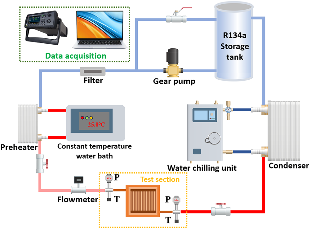
Figure 1: Schematic diagram of experimental system
Fig. 2 shows the schematic view of the test section with micro-channel, which is composed of copper heating module, copper-based microchannel heat sink, PTFE (polytetrafluoroethylene) gasket, high-transmittance polysulfone resin observation cover plate, rubber sealing gasket and stainless-steel backing plate. The micro-channel region has a surface area of 50 mm × 50 mm. The observation cover plate is securely mounted atop the heat sink with fastening bolts to facilitate visualization of flow patterns. The PTFE gasket is designed to provide a dual-sealing function, preventing working fluid leakage while maintaining gas-tight integrity of the test section under high-pressure conditions. The rubber sealing gasket is precisely positioned between the stainless-steel backing plate and the transparent observation window to prevent direct rigid contact between these components. The copper heating module is thermally energized by an array of 15 stainless-steel heating cartridges, with power input precisely regulated through an adjustable AC power supply. The external surfaces of the copper heating block are encapsulated with a multi-layer fiberglass insulation structure to minimize thermal dissipation to the ambient environment. The test section is an integrated design, which avoids the contact thermal resistance between the copper heating block and the microchannel heat sink caused by the assembly gap in the split experimental section.
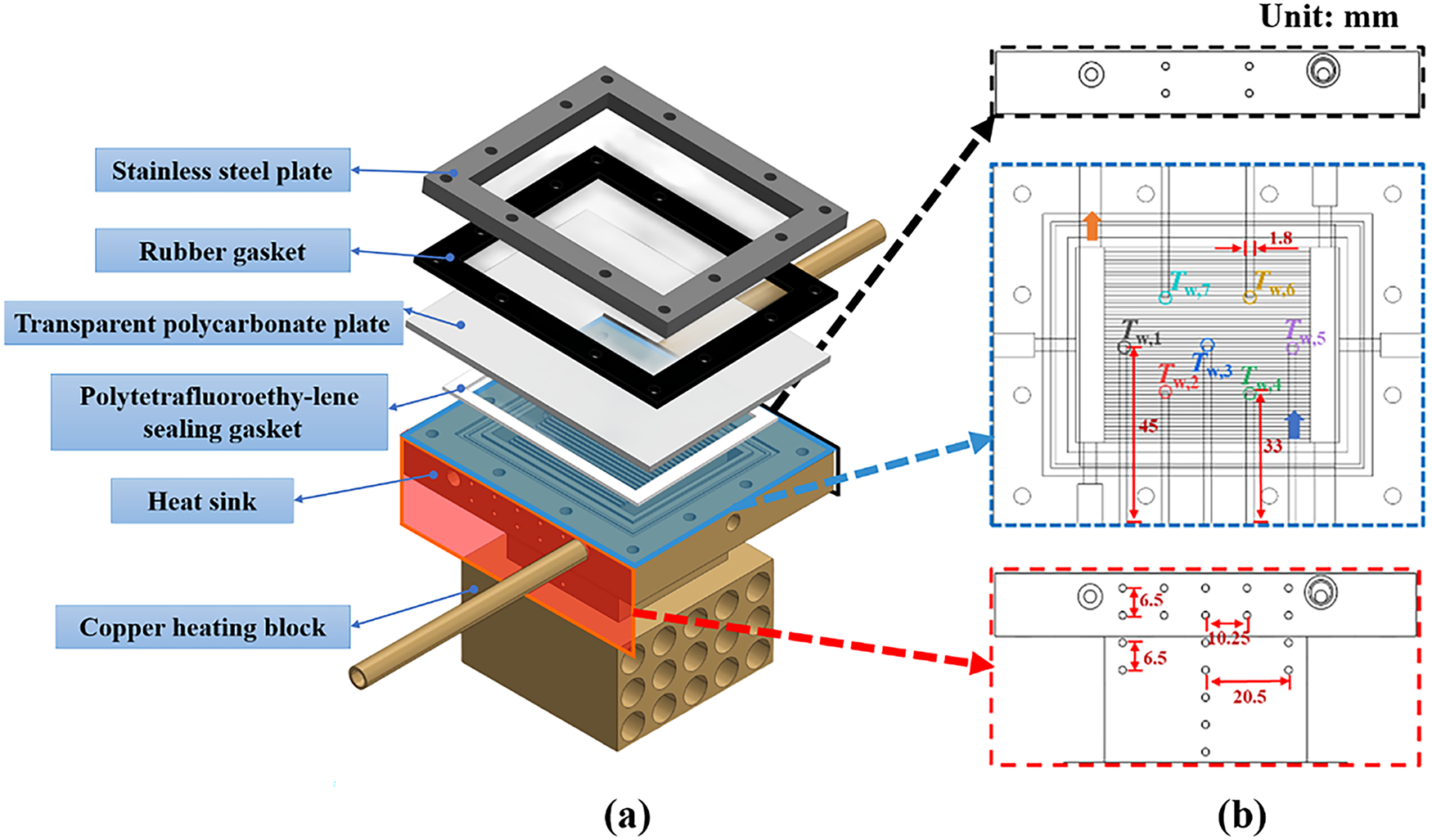
Figure 2: Schematic diagram of test section. (a) Exploded view of the test section; (b) Dimensions and Thermocouple Arrangement
At the base of the copper block, an array of 10 mm diameter × 60 mm long bores accommodates cartridge heaters with a total thermal load of 200 W. During experiments, the copper block assembly containing both microchannels and heating elements was insulated with fiberglass wrapping on both bottom and side surfaces to minimize heat loss to the environment. For temperature measurement beneath the microchannels, fourteen calibration holes (arranged in a 7 × 2 matrix) were drilled into the heat sink to accommodate thermal sensors. Precisely calibrated T-type thermocouples (Omega) were inserted uniformly beneath the microchannel region, as illustrated in Fig. 2b.
This study investigates two distinct microchannel configurations: SP-MCs and sintered porous parallel microchannels. The SP-MCs were fabricated by direct micromachining on the upper surface of a copper block. The monolithic construction eliminates interfacial thermal resistance concerns. In contrast, the parallel-structured porous microchannels were fabricated through copper powder sintering, with the resulting architecture shown in Fig. 3.
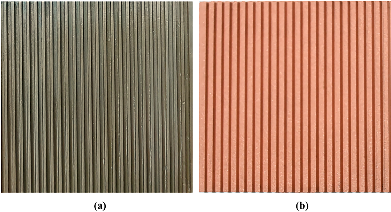
Figure 3: Photographs of microchannels with different structures. (a) SP-MCs; (b) PP-MCs
The microchannel surface features 27 parallel square channels fabricated either by CNC micro-milling or sintering on the copper block surface, covering a footprint of 30 mm × 40 mm. Each individual channel has a cross-sectional area of 1 × 1 mm with a length of 30 mm. The inlet and outlet are diagonally arranged to enhance flow distribution uniformity. Both rectangular inlet and outlet plenums were manufactured using micro-milling techniques.
2.2 Preparation of Porous-Coated Surface
The porous microchannels were fabricated through powder metallurgy using spherical copper particles with an average diameter of 75 μm. As illustrated in the accompanying schematic, the manufacturing process consists of two critical stages: sintering and diffusion bonding. Initially, a graphite mold was precision-machined according to the microchannel design specifications. The copper powder was uniformly filled into the mold cavity, leveled, and compacted using a graphite pressing plate. The assembly was then transferred to a vacuum sintering furnace, where it underwent thermal treatment at 900°C for 2 h. During sintering, atomic diffusion at particle interfaces facilitated neck formation between copper particles, resulting in a mechanically robust porous microstructure with enhanced structural integrity. Following sintering, the porous microchannel was positioned in an edgeless mold, ensuring intimate contact between its lower surface and a smooth copper substrate (heat sink surface). The assembly was subjected to diffusion bonding in a vacuum furnace under an applied pressure while maintaining the temperature at 900°C. This process promoted accelerated atomic interdiffusion at the interface, achieving a metallurgically bonded joint with minimized thermal contact resistance and improved heat transfer efficiency. After cooling to ambient temperature, the graphite mold was removed, yielding the final test section with integrated PP-MCs. The porosity (φ) of the microchannels was determined by measuring the mass (M) and volume (V) of the sintered copper structure at room temperature, calculated as:
where, ρcu denotes the theoretical density of solid copper.
For each microchannel configuration, three identical porous structures were fabricated via the sintering process. The porosity of each sintered copper porous microchannel was individually determined, and the average value was calculated to represent the overall porosity of the fabricated structures. Based on this methodology, the mean porosity of the PP-MCs in this study was determined to be 0.3695.
To clearly illustrate the fabrication process of sintered porous microchannels, Fig. 4 shows a detailed schematic diagram of the manufacturing procedure. Fig. 5 presents comparative scanning electron microscopy (SEM) images characterizing the surface morphology of both configurations: (a) the solid smooth copper microchannels and (b) the sintered porous microchannel matrix.
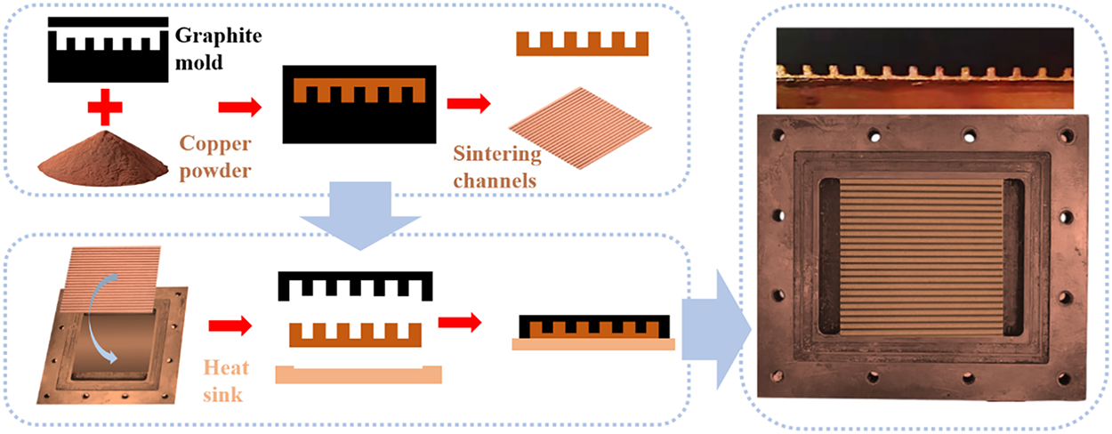
Figure 4: Schematic diagram of the preparation–sintering process of porous microchannels
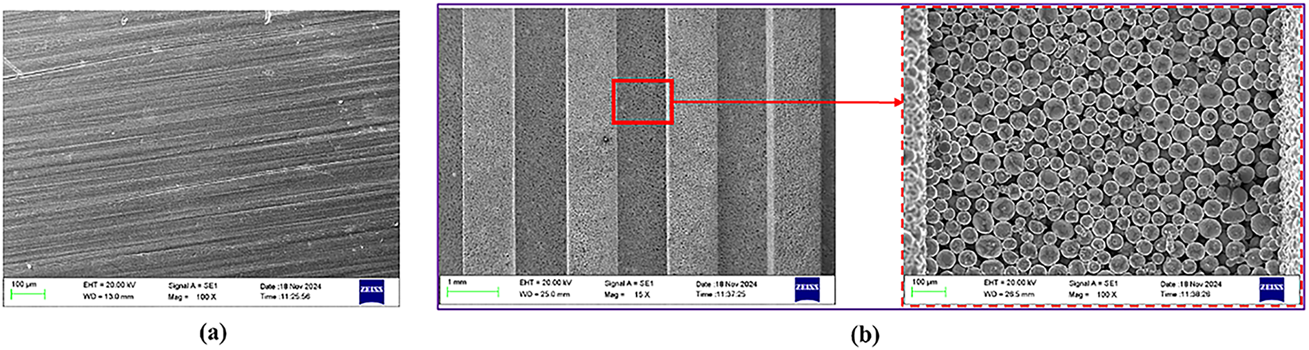
Figure 5: Scanning electron microscopy (SEM) of the microstructure of the channel surface. (a) Smooth structure; (b) Porous structure
In this study, refrigerant R134a was chosen as the working fluid, and the flow boiling characteristics within different microchannel heat sinks were explored under near-saturation inlet condition (5 ± 0.2°C) at two different mass fluxes, and the specific experimental conditions are summarized in Table 1.
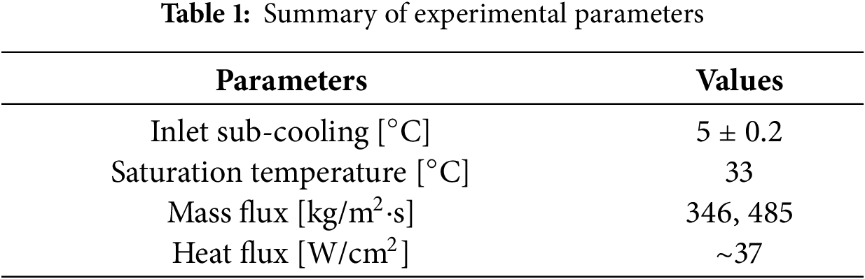
The mass fluxes of 346 and 485 kg/m2·s were selected to represent typical intermediate to high flow conditions in microchannel cooling applications. This selection allows for the investigation of the effects of flow momentum on bubble dynamics, flow patterns, and the onset of instability, covering a relevant operational range for practical systems.
The experimental setup involved first brazing the microchannel heat sink to a copper heating block, which was then integrated into a closed-loop flow system. The system underwent thorough leak testing and vacuum degassing procedures to ensure experimental integrity. The test protocol commenced with complete degassing of the working fluid in the reservoir, followed by system activation including pump startup, preheater operation, and stabilization at predetermined mass flow rate and pressure conditions. Upon achieving stable conditions, the heating process was initiated by applying a controlled voltage to the cartridge heaters through an AC power supply. Temperature and pressure data recording began only after confirming steady-state thermal conditions. The experimental procedure involved systematically increasing the heating power while continuously monitoring the thermal response. Testing was terminated when either uncontrolled temperature rise occurred or the system failed to reach equilibrium. The heating process was initiated by applying a controlled voltage to the cartridge heaters through an AC power supply. The system was considered to have reached steady state when the temperatures measured by all thermocouples varied by less than ±0.2°C over a continuous period of 10 min. Temperature and pressure data recording began only after confirming these steady-state thermal conditions. Upon completing all specified flow rate conditions, the system was shut down for subsequent test configurations.
Prior to the formal flow boiling experiments, heat loss from the test section to the ambient was calibrated under single-phase conditions. By comparing the electrical power input with the sensible heat gain of the fluid, the heat loss was estimated to be less than 2.5% of the total input power across the entire range of operating conditions investigated. Therefore, heat loss is considered negligible in the subsequent data reduction process.
2.4 Data Reduction and Uncertainty Analysis
The entire test section was fabricated from copper, which has a thermal conductivity of 401 W/(m·K). The copper block was fully insulated with thermal insulation material and foam padding, leaving only the heat transfer surface exposed to the working fluid (R134a). This configuration ensured that most of the heat was transferred to the working fluid. In the microchannels, the baseline heat flux was calculated based on the vertical temperature gradient:
The average heat transfer coefficient is calculated using the following equation:
where Tw is the temperature of the heated wall at the base of the microchannel, Tf is the fluid temperature at the base of the microchannel. For smooth solid copper microchannels, Tw is determined based on the temperature readings from the top thermocouples and the heat flux calculated using Fourier’s law of one-dimensional heat conduction. The wall temperature is given by:
where Tw,i is the local wall temperature along the flow direction, which is calculated under the assumption of one-dimensional heat conduction using Fourier’s law of heat conduction:
where Tc,i (i = 1, 2, 3, 4, 5, 6, 7) is the external wall temperature measured by the top-row T-type thermocouples near the microchannel base, δ is the vertical distance between the top thermocouples and the channel base, qi is the local heat flux, calculated as:
In the flow boiling experiments with PP-MCs, the thermal resistance exhibits an opposite trend due to the significantly lower thermal conductivity of the sintered porous layer compared to solid copper. Consequently, as illustrated in Fig. 6, the average wall temperature Tw,ave can be determined using the one-dimensional heat conduction equation:
where Rtotal denotes the total thermal resistance between the top-row thermocouples and the channel base, which equals the sum of the thermal resistance of solid copper (Rcu) and that of the sintered porous layer (Rp), calculated as follows:
where keff is the effective thermal conductivity of the sintered porous layer, calculated as the porosity-weighted average of the thermal conductivities of solid copper and the working fluid in the pores, given by:
where kf is the thermal conductivity of the near-wall fluid, evaluated at the mean temperature between the wall and fluid as the reference temperature.
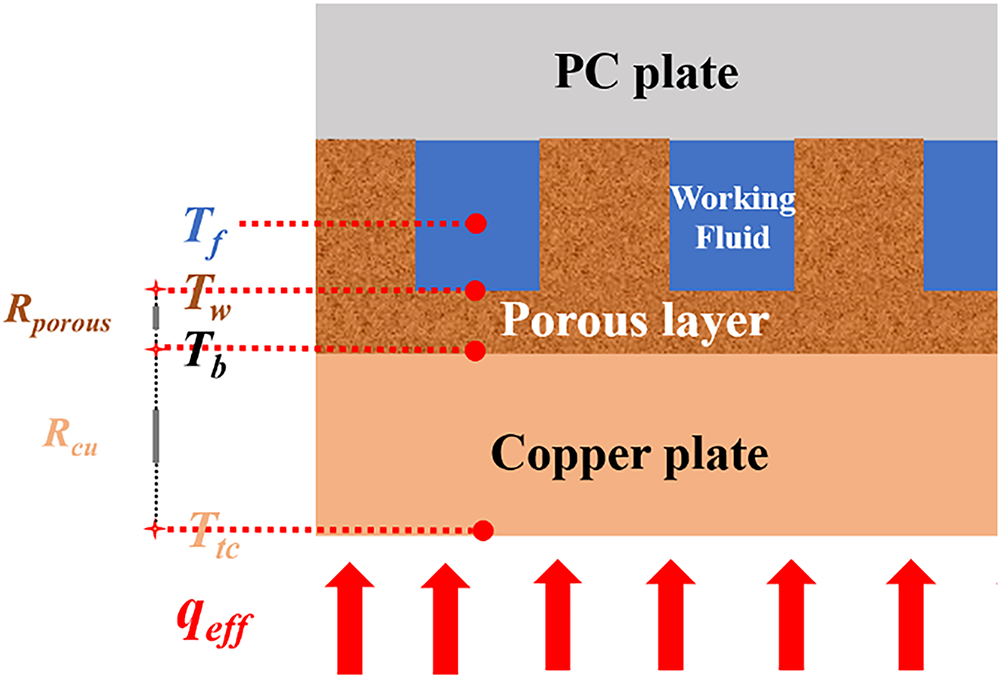
Figure 6: Heat conduction process in the sintered microchannel
The mass flux is calculated as:
where M is the mass flow rate, N denotes the number of channels, and Ach represents the cross-sectional area of a single rectangular channel.
The outlet quality is calculated as:
where Tf,in and Tf,sat represent the fluid inlet temperature and saturation temperature, respectively.
The total pressure drop in microchannel boiling is determined by evaluating the pressure variation between the microchannel inlet and outlet, calculated as follows:
2.4.2 Measurement Accuracy and Experimental Uncertainty
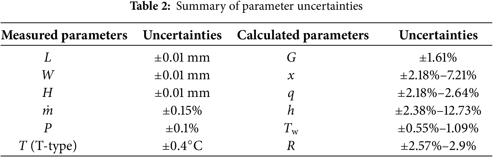
The measurement uncertainties were determined based on the accuracies of the sensors and thermocouples. The uncertainty of calculated parameters was evaluated using the method proposed by Moffat [16], expressed as:
where Ri denotes the indirectly calculated parameter composed of several directly measured parameters, while the uncertainty of the derived parameter UR is propagated from the uncertainties of the measured parameters
The reliability of the experimental data is underpinned by several factors: (1) the system’s excellent insulation ensured that the vast majority of input power was transferred to the working fluid; (2) the experimental setup and procedure have been refined and used in our previous published works, demonstrating consistent performance; (3) the observed physical phenomena, such as the distinct reduction of ONB superheat in porous channels and the typical trends of boiling curves, align well with established physical principles reported in the literature, providing indirect validation of the setup’s credibility. Furthermore, the comprehensive uncertainty analysis confirms the precision of the reported data.
Fig. 7 illustrates the effects of channel configuration and mass flux on boiling curves. Under subcooled conditions prior to onset of nucleate boiling (ONB), the heat flux remains relatively low and increases gradually with wall superheat, as convective heat transfer dominates before the ONB, resulting in an insignificant change in the boiling curve. Beyond ONB, the heating power is primarily absorbed by the working fluid through phase change, causing a sharp increase in the slope of the boiling curve. As heat flux continues to rise, wall temperature increases moderately with corresponding growth in wall superheat. However, when heat flux reaches a certain level, the slope of the boiling curve begins to decrease progressively, indicating the imminent occurrence of critical heat flux (CHF). The ONB was determined through a combined approach. Primarily, it was identified as the point on the boiling curve where a consistent and unambiguous deviation from the linear trend of single-phase heat transfer commenced, typically characterized by a marked increase in the slope of the heat flux versus wall superheat curve. This determination was corroborated and visually confirmed by the observation of the first stable, continuously growing vapor bubbles emanating from the heated surface in the high-speed flow visualization recordings.
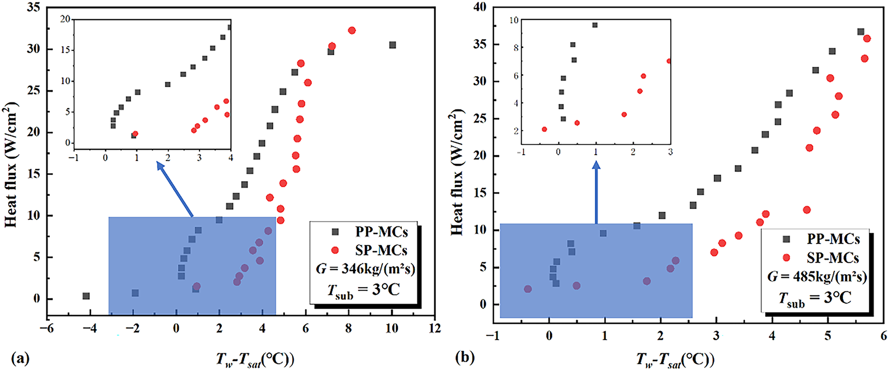
Figure 7: Boiling curves in different microchannels. (a) G = 346 kg/(m2·s); (b) G = 485kg/(m2·s)
At identical mass flux conditions, different channel configurations exhibit distinct characteristics. Taking the case of 346 kg/(m2·s) as an example, the porous parallel microchannel demonstrates an ONB wall superheat of merely 0.13°C, whereas the smooth parallel microchannel requires a significantly higher wall superheat of 2.2°C at the same mass flux. This represents an approximately 2°C reduction in superheat for the porous configuration, clearly indicating that the micro-scale pores in PP-MCs effectively promote early bubble nucleation.
Within identical channel configurations, mass flux also exerts a pronounced influence on heat transfer performance. For the porous parallel microchannel, when the mass flux increases from 346 to 485 kg/(m2·s), the ONB wall superheat rises from 0.13°C to 0.24°C. In contrast, the smooth parallel microchannel exhibits an increase in ONB wall superheat from 2.2°C to 2.5°C under the same mass flux variation. At higher mass fluxes, the enhanced replenishment of working fluid following phase change not only facilitates greater heat removal but also promotes bubble advection downstream, effectively mitigating localized pressure buildup caused by bubble stagnation. However, the smooth parallel microchannel demonstrates superior CHF performance at equivalent mass flux conditions. This is attributed to its smooth surface enhancing convective evaporation effects under high heat flux conditions. While the porous structure exhibits excellent permeability, rapid liquid absorption and evaporation in upstream regions lead to insufficient wetting in downstream porous channels. This accelerated dryout phenomenon causes the porous surface to reach CHF more rapidly.
3.2 Heat Transfer Characteristics
Controlled inlet subcooling was employed to enable more accurate calculation of the exit vapor quality in both test sections, thereby eliminating potential errors in local pressure determination [3]. Consequently, all experimental conditions maintained a constant inlet subcooling of 5°C.
Fig. 8 presents the flow boiling heat transfer coefficients for both porous and SP-MCs as functions of heat flux (Fig. 8a) and exit vapor quality (Fig. 8b) at mass fluxes of 346 and 485 kg/(m2·s). In the initial stage, the porous parallel microchannels exhibited rapid enhancement of heat transfer coefficients at both mass fluxes, while the SP-MCs showed comparatively lower enhancement rates. During this phase, the porous microchannels demonstrated significantly superior heat transfer performance. As the critical heat flux (CHF) condition was approached, the growth rate of heat transfer coefficients in porous microchannels gradually diminished. In contrast, the smooth microchannels maintained a nearly constant enhancement rate, ultimately surpassing the performance of their porous counterparts.
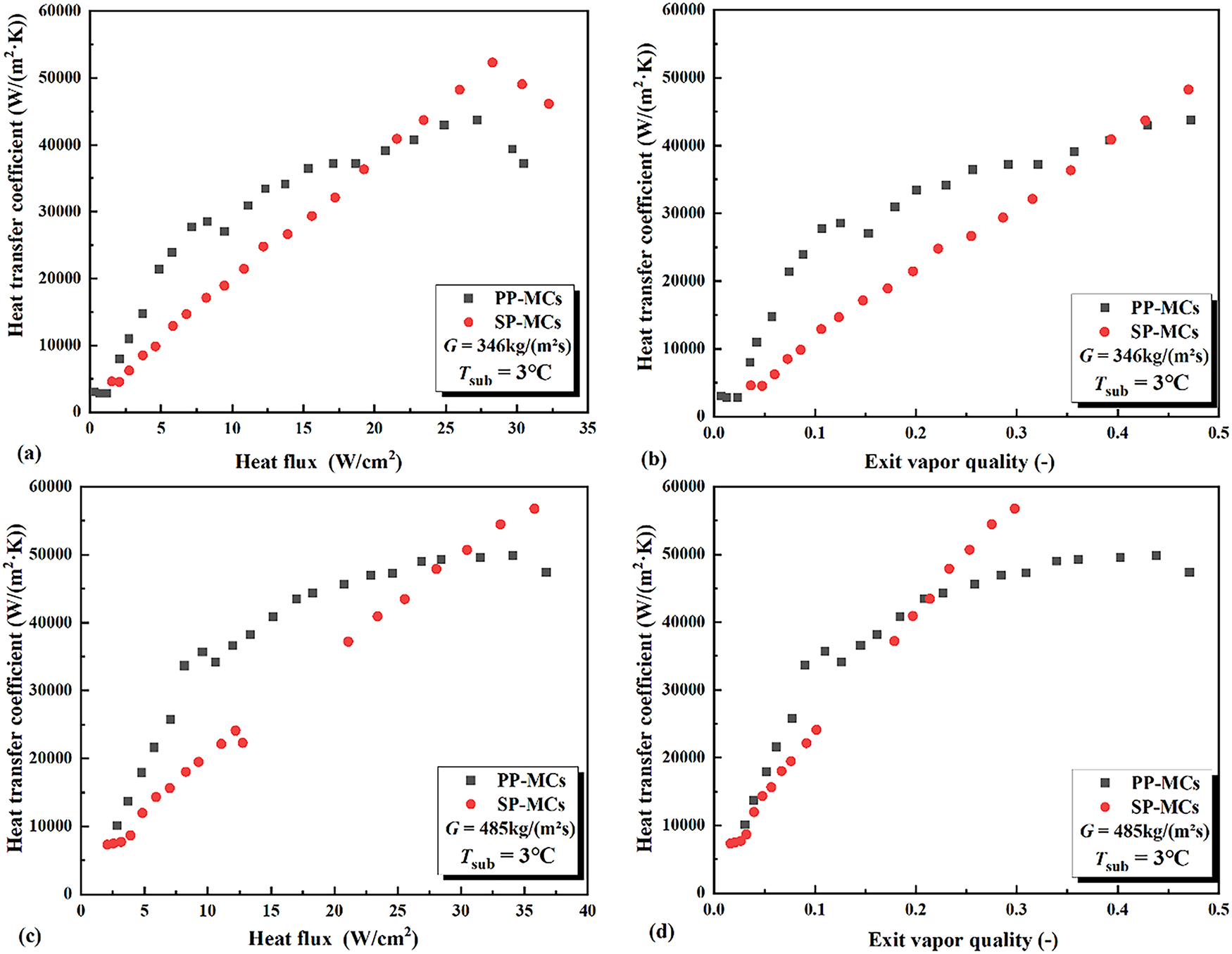
Figure 8: The variation of heat transfer coefficient with heat flux (a,c) and outlet vapor quality (b,d) in microchannels of different configurations
Under identical mass flux conditions, the sintered porous structure consistently demonstrates superior heat transfer coefficients compared to the smooth parallel structure at low-to-medium heat flux levels. At a mass flux of 346 kg/(m2·s), when the heat flux remains below 20 W/cm2 and the vapor quality is less than 0.4, the sintered porous microchannel exhibits higher heat transfer coefficients than its smooth counterpart, with the performance gap initially widening before gradually narrowing. When the mass flux increases to 485 kg/(m2·s), the crossover point where both structures achieve equivalent heat transfer performance occurs at 30 W/cm2 and vapor quality of 0.2, with the sintered porous structure maintaining superior performance below these thresholds.
The enhanced thermal performance of sintered porous structures stems from their larger specific surface area, which promotes thin-film evaporation, while the micro-pores and cavities serve as additional nucleation sites that intensify nucleate boiling heat transfer. In contrast, the smooth microchannel’s lack of active nucleation sites results in significantly inferior heat transfer performance at low-to-medium heat fluxes. However, at elevated heat fluxes, the smooth structure facilitates convective evaporation, whereas the confined microstructures in sintered porous channels restrict bubble formation, growth, and detachment processes. This limitation impedes efficient heat removal, reduces effective heat transfer area through surface attachment, and promotes localized hot spot formation.
The variation of heat transfer coefficients with both heat flux and exit vapor quality follows consistent trends. As reported in Reference [3], the variation of heat transfer coefficients with exit vapor quality exhibits similar characteristics to those shown in Fig. 8, where the flow patterns are categorized into bubbly, slug, annular, and partial dryout regimes. In the low-to-medium vapor quality region (bubbly and slug flows), convective heat transfer and nucleate boiling dominate the heat transfer mechanisms. The sintered porous microchannel’s abundance of nucleation sites yields superior thermal performance during this phase, consistent with the aforementioned analysis. At higher vapor qualities, the heat transfer mechanism transitions from nucleate boiling to film boiling, where the liquid film impedes direct contact between the wall and subsequent liquid, increasing local thermal resistance and degrading heat transfer performance, which is the thermal deterioration phenomenon.
As heat flux continues to increase, elevated wall superheat and vapor quality drive the transition to film boiling. The sintered porous structure exhibits more pronounced liquid film attachment effects, resulting in poorer thermal performance at high heat fluxes. Furthermore, the heat transfer coefficient declines more rapidly with increasing heat flux in PP-MCs compared to smooth channels under these conditions.
Fig. 9 illustrates the effect of mass flux on flow boiling heat transfer coefficients in different microchannel configurations. Notably, the influence of mass flux varies significantly depending on the microchannel structure.
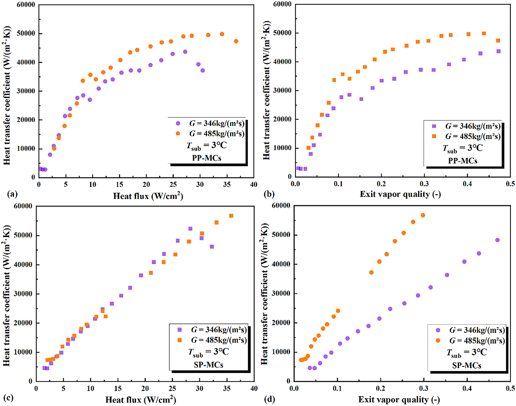
Figure 9: The effect of mass flux on heat transfer coefficient in microchannels with PP-MCs (a,b) and SP-MCs (c,d)
For SP-MCs, the heat transfer coefficient exhibits an approximately linear increase with mass flux. At heat fluxes below 10 W/cm2, higher mass fluxes paradoxically result in lower heat transfer coefficients under identical heat flux conditions. This phenomenon stems from enhanced nucleate boiling and earlier onset of convective evaporation heat transfer at lower mass fluxes. However, the improvement in heat transfer performance with increasing mass flux remains limited in smooth microchannels, as their thermal performance is constrained primarily by structural characteristics rather than mass flux. The smooth surface geometry inherently suppresses nucleate boiling at low-to-medium heat fluxes, thereby restricting phase change quantities. Consequently, increased mass flux mainly leads to greater liquid phase accumulation at the outlet, as evident in Fig. 9d.
At lower mass fluxes (e.g., 346 kg/(m2·s)), reduced flow momentum coupled with elevated temperatures promotes localized surface overheating and dryout [1]. This condition leads to more rapid vapor quality development and consequently earlier occurrence of heat transfer deterioration, which is a trend observed across all microchannel configurations under study. This deterioration in heat transfer performance is likely closely related to the transition in flow characteristics. As shown in Figs. 8 and 9, under high heat flux/high vapor quality conditions, although the overall flow in the porous channels remains stable, localized vapor accumulation may lead to an increase in flow resistance (as indicated by the rising pressure drop trend) and a reduction in the effective flow cross-sectional area. This exacerbates liquid film attachment and localized dryout, ultimately resulting in the degradation of heat transfer. This suggests that the decline in heat transfer performance is a result of the combined effects of flow pattern evolution and thermal-hydraulic instability. When the heat flux and vapor quality exceed certain critical values (~30 W/cm2, x > 0.2), a reversal in heat transfer performance can be observed, with the smooth microchannels (SP-MCs) outperforming the porous microchannels (PP-MCs). The fundamental mechanism behind this performance “crossover point” can be attributed to an imbalance between capillary liquid supply and evaporation demand within the porous structure. Under extremely high heat flux conditions, the evaporation rate within the porous skeleton increases sharply, potentially surpassing the maximum liquid supply rate provided by its intrinsic capillary pumping capacity. This imbalance prevents liquid from being timely replenished to all pores and heated walls, leading to the formation of local dry spots. These dry spots significantly reduce the effective heat transfer area and introduce extremely high thermal resistance at the solid–gas interfaces, ultimately resulting in a sharp deterioration of heat transfer performance. In contrast, SP-MCs primarily rely on a forced convective evaporation mechanism in the high vapor quality region, where their performance is more influenced by flow momentum and less susceptible to such localized failures induced by capillary limitations, thus demonstrating better adaptability under high thermal loads.
In microchannel flow boiling, flow instability significantly impacts both heat transfer performance and system stability.
The interaction between gas-liquid phases and micro-scale effects in microchannels can trigger premature onset of critical conditions, thereby affecting the overall thermal performance of the system. Flow instability not only induces fluctuations in heat transfer performance but may also lead to severe thermal-hydraulic instabilities, compromising system safety and reliability. Therefore, investigating the role of flow instability in microchannel flow boiling is essential for a deeper understanding of heat transfer mechanisms, optimizing microchannel design, and improving the flow boiling performance of low-boiling-point working fluids, ultimately enhancing the overall efficiency of microchannel cooling systems.
Since the influence mechanisms of heat flux and mass flux on flow instability have been thoroughly analyzed in Sections 3.1 and 3.2, this section primarily focuses on the effects of different porous microchannel structures and inlet subcooling on flow boiling instability. The stability of two-phase flow was evaluated using standard deviation (STD), with particular emphasis on fluctuations in inlet-outlet pressure drop. The expression for STD is given by Eq. (17):
Fig. 10 illustrates the influence of channel structure on pressure drop instability. Under the conditions of mass flux 346 kg/(m2·s) and heat flux 5.8 W/cm2, the sintered porous structure exhibits a maximum pressure drop amplitude of 12.7 kPa with a standard deviation of 2.36, while the smooth parallel structure shows significantly higher values of 16.23 kPa and 3.77 at the same mass flux, respectively. This corresponds to 21.7% and 37.7% reductions in maximum amplitude and standard deviation for the sintered structure compared to the smooth configuration.
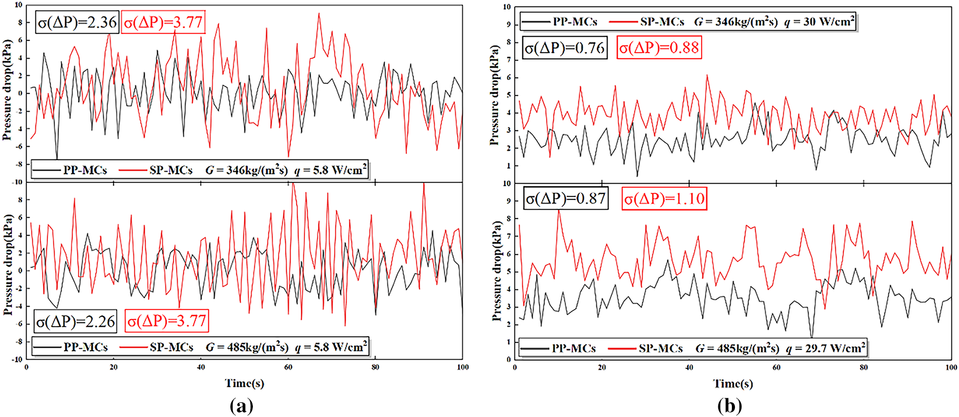
Figure 10: The effect of channel configuration on pressure drop instability in different heat flux. (a) q = 5.8 W/cm2; (b) q = 5.8 W/cm2
When the mass flux increases to 485 kg/(m2·s), the pressure drops characteristics demonstrate more pronounced differences. The smooth parallel structure registers a maximum amplitude of 16.43 kPa (STD = 3.77), whereas the sintered porous structure achieves substantially lower values of 8.8 kPa (STD = 2.26), representing reductions of 46.4% and 44.8%, respectively. These results clearly indicate that the sintered porous structure maintains superior pressure drop stability across both mass flux conditions, with its advantages becoming more evident at higher flow rates.
This enhanced stability can be attributed to the capillary pumping effect induced by the sintered porous layer, which facilitates more efficient liquid replenishment to the heated surface, thereby improving flow boiling stability. Additionally, the sintered microchannels promote the formation of smaller initial bubble size, which undergo controlled growth before merging into the main flow, resulting in smoother flow behavior and reduced flow disturbances. Furthermore, the sintered structure helps maintain uniform vapor-liquid distribution, mitigating flow instabilities and preventing localized vapor blockages that could otherwise lead to flow maldistribution.
When the heat flux is approximately 30 W/cm2, the STD of the pressure drop within each microchannel is lower than that under low heat flux conditions. Furthermore, the fluctuation amplitude is significantly reduced, with the maximum fluctuation amplitude decreasing to 3.6~5.8 kPa and the standard deviation reduced to 0.76–1.10. This represents a reduction exceeding 50% compared to the low heat flux case. This improvement is primarily attributed to the more stable flow pattern established at this heat flux level. Under high heat flux conditions, the evaporation process of the working fluid becomes more vigorous, generating a greater vapor volume. This promotes a more developed gas-liquid two-phase flow. This well-developed two-phase flow acts as a natural buffer against pressure fluctuations, mitigating localized pressure spikes and thereby improving overall flow stability.
Fig. 11 shows the relationship between the inlet-outlet pressure drop and the heat flux for different microchannel structures at mass velocities of 346 and 485 kg/(m2·s). Under certain saturation temperature and pressure conditions, the pressure drop in each microchannel gradually increases with the rise in heat flux. The increase in heat flux accelerates the phase change rate of the refrigerant, leading to the generation of more vapor bubbles. The formation, flow, and detachment of these bubbles within the channels enhance the flow resistance. Within the experimental range and at the same mass velocity, the pressure drop in the SP-MCs is consistently higher than that in the porous parallel microchannels. For instance, at a mass flux of 346 kg/(m2·s), the difference in the inlet-outlet pressure drops between the porous and SP-MCs is approximately 1 kPa. At a mass flux of 485 kg/(m2·s), this difference decreases from 1 kPa at the initial heating stage to 0.56 kPa at the final heating stage. The maximum pressure drop observed in the porous parallel microchannels within the experimental range is 5.63 kPa, while that in the SP-MCs is 6.16 kPa.
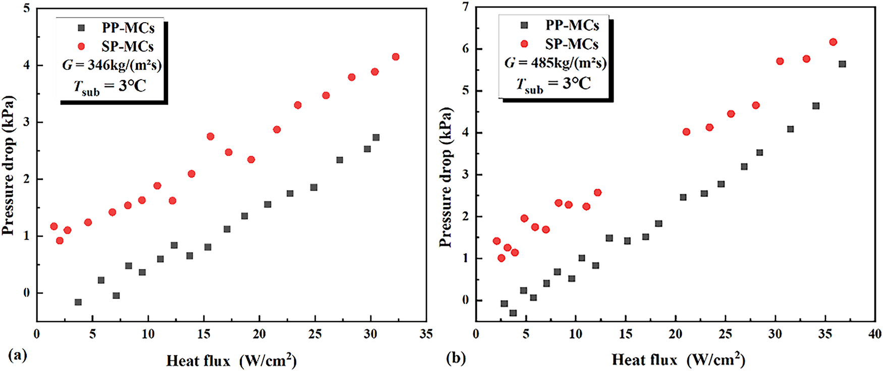
Figure 11: The variation of inlet-outlet pressure drops with heat flux for different microchannel configurations. (a) G = 346 kg/(m2·s); (b) G = 485 kg/(m2·s)
Firstly, the SP-MCs, lacking surface roughness and porous structures, exhibit a thicker flow boundary layer, resulting in greater flow resistance of the fluid within the channels. Additionally, the rapid generation and flow of vapor bubbles can easily cause local blockages. On smooth surfaces, the larger contact area between the bubbles and the wall leads to higher bubble detachment resistance, causing bubbles to accumulate on the wall. This further increases flow resistance, resulting in intense velocity fluctuations and higher local acceleration pressure drops. At higher heat fluxes, due to intense fluid phase change, the flow resistance increases further, leading to a higher total inlet-outlet pressure drop in the SP-MCs compared to the porous microchannels.
The porous structure of the porous microchannels not only disrupts the flow boundary layer and enhances local turbulent mixing but also provides abundant nucleation sites. This enables bubbles to form uniformly at lower superheat levels rather than concentrating in a few hot spots. Consequently, bubble growth and detachment become more stable, avoiding abrupt flow pattern changes and thereby reducing additional flow resistance caused by flow instability. Meanwhile, the sintered porous structure reduces the contact area between bubbles and the wall, lowering bubble detachment resistance and further decreasing the pressure drop.
This experimental study investigates the flow boiling characteristics of refrigerant R134a in sintered porous (PP-MCs) and smooth (SP-MCs) parallel microchannels under controlled conditions (inlet subcooling of 5 ± 0.2°C, saturation temperature of 33°C, mass fluxes of 346 and 485 kg/m2·s). The results reveal a dual-phase behavior of the porous microchannels: under low-to-medium heat flux and low vapor quality conditions, the porous microstructure enhances performance by providing abundant nucleation sites and augmented capillary wicking, which significantly reduces ONB superheat, improves the heat transfer coefficient, and increases flow stability. In contrast, under high heat flux and high vapor quality conditions, potential capillary supply limitations cause the performance of PP-MCs to be surpassed by SP-MCs, which rely on a more stable forced convective evaporation mechanism. The main conclusions are as follows:
1. Bubble Nucleation and Activation: The sintered porous microstructure significantly optimizes bubble nucleation behavior. The abundant micropores and cavities provided by the porous surface act as stable vaporization nuclei, markedly reducing the wall superheat required for the onset of nucleate boiling (ONB). At a mass flux of 346 kg/(m2·s), the ONB superheat for the porous microchannels was only 0.13°C, compared to 2.2°C for the smooth microchannels. This indicates that the porous structure effectively addresses the high nucleation barrier at the microscale, enabling earlier and more gradual initiation of boiling. Furthermore, the porous structure promotes uniform bubble generation and controlled growth, preventing the concentration of bubbles in a few localized hot spots and establishing a foundation for stable two-phase flow.
2. Heat Transfer Coefficient: The heat transfer performance of the porous microchannels is highly dependent on heat flux and outlet vapor quality. In the low to medium heat flux range (<20–30 W/cm2) and at low vapor quality (x < 0.2–0.4), the heat transfer coefficient of the porous microchannels is significantly higher than that of the smooth microchannels. The enhanced heat transfer mechanism is primarily attributed to the large specific surface area, which facilitates thin-film evaporation, and the intensified nucleate boiling due to the microporous structure. However, under high heat flux and high vapor quality conditions, the performance of porous structures may be inferior to that of smooth channels, which rely on a stable forced convective evaporation mechanism. This is primarily due to the potential occurrence of a capillary supply limit within the porous structure, where the evaporation demand exceeds the capillary replenishment capacity of the liquid. This imbalance leads to the formation of local dry spots and a consequent reduction in effective heat transfer area, thus degrading overall thermal performance. This is because the porous structure is prone to liquid film adhesion, pore dry-out, and flow channel blockage under high vapor quality conditions, leading to premature critical heat flux (CHF) and heat transfer deterioration. In contrast, the smooth surface favors a stable convective evaporation mechanism, demonstrating better adaptability to high-temperature conditions.
3. Pressure Drop and Flow Stability: A beneficial phenomenon observed in this study is that the PP-MCs significantly enhance heat transfer performance while simultaneously reducing flow resistance and improving system stability. Under all experimental conditions, the total pressure drop in the porous microchannels was lower than that in the smooth microchannels. This is due to the porous structure disrupting the laminar boundary layer, enhancing turbulent mixing, and reducing the contact area between bubbles and the wall, thereby decreasing bubble detachment resistance and frictional pressure drop. More importantly, the capillary pumping effect generated by the porous layer ensures continuous liquid replenishment, effectively suppressing intermittent boiling and flow oscillations. As a result, the fluctuation amplitude and standard deviation (STD) of the inlet–outlet pressure drop in the porous microchannels were reduced by up to 46.4% and 44.8%, respectively, demonstrating exceptional flow stability. This is crucial for high-performance and high-reliability electronic cooling systems.
Acknowledgement: The authors acknowledge Beijing Jiaotong University for providing the experimental space and partial equipment.
Funding Statement: This research is supported by the Beijing Municipal Science & Technology Commission (Z231100006123010), Guizhou Provincial Major Scientific and Technological Program (XKBF (2025) 031) and a grant from Tianjin Key Laboratory of Refrigeration Technology (2025TKLRT002).
Author Contributions: The authors confirm contribution to the paper as follows: Conceptualization, Shuo Wang and Huiming Wang; formal analysis, Huiming Wang; investigation, Shuo Wang and Huiming Wang; resources, Ying Zhang and Zhiqiang Zhang; data curation, Shuo Wang; writing—original draft preparation, Shuo Whang; writing—review and editing, Li Jia; supervision, Li Jia; project administration, Shuo Wang. All authors reviewed the results and approved the final version of the manuscript.
Availability of Data and Materials: The data that support the findings of this study are available from the corresponding author upon reasonable request.
Ethics Approval: Not applicable.
Conflicts of Interest: The authors declare no conflicts ofinterest to report regarding the present study.
References
1. Zhang Z, Wu Y, He K, Yan X. An experimental study on flow boiling heat transfer in porous-ribbed micro-channels. Appl Therm Eng. 2024;250:123443. doi:10.1016/j.applthermaleng.2024.123443. [Google Scholar] [CrossRef]
2. Tuckerman DB, Pease RF. High-performance heat sinking for VLSI. IEEE Electron Device Lett. 2005;2(5):126–9. doi:10.1109/EDL.1981.25367. [Google Scholar] [CrossRef]
3. Dang C, Jia L, Peng Q, Yin L, Qi Z. Comparative study of flow boiling heat transfer and pressure drop of HFE-7000 in continuous and segmented microchannels. Int J Heat Mass Transf. 2020;148:119038. doi:10.1016/j.ijheatmasstransfer.2019.119038. [Google Scholar] [CrossRef]
4. Shi H, Grall S, Yanagisawa R, Jalabert L, Paul S, Kim SH, et al. Chip cooling with manifold-capillary structures enables 105 COP in two-phase systems. Cell Rep Phys Sci. 2025;6(4):102520. doi:10.1016/j.xcrp.2025.102520. [Google Scholar] [CrossRef]
5. O’Neill LE, Mudawar I. Review of two-phase flow instabilities in macro- and micro-channel systems. Int J Heat Mass Transf. 2020;157:119738. doi:10.1016/j.ijheatmasstransfer.2020.119738. [Google Scholar] [CrossRef]
6. Zhang Z, Wu Y, He K, Yan X. Experimental investigation into flow boiling heat transfer and pressure drop in porous coated microchannels. Int J Heat Mass Transf. 2024;218:124734. doi:10.1016/j.ijheatmasstransfer.2023.124734. [Google Scholar] [CrossRef]
7. Hu H, Jiang P, Huang F, Xu R. Role of trapped liquid in flow boiling inside micro-porous structures: pore-scale visualization and heat transfer enhancement. Sci Bull. 2021;66(18):1885–94. doi:10.1016/j.scib.2021.05.019. [Google Scholar] [PubMed] [CrossRef]
8. Pranoto I, Leong KC. An experimental study of flow boiling heat transfer from porous foam structures in a channel. Appl Therm Eng. 2014;70(1):100–14. doi:10.1016/j.applthermaleng.2014.04.027. [Google Scholar] [CrossRef]
9. Azizifar S, Song M, Chao CYH, Hosseini SH, Pekař L. A numerical study of multiphase flow boiling heat transfer of nanofluids in the horizontal metal foam tubes. Int J Thermofluids. 2024;22:100605. doi:10.1016/j.ijft.2024.100605. [Google Scholar] [CrossRef]
10. Azizifar S, Ameri M, Behroyan I. Subcooled flow boiling of water in a metal-foam tube: an experimental study. Int Commun Heat Mass Transf. 2020;118:104897. doi:10.1016/j.icheatmasstransfer.2020.104897. [Google Scholar] [CrossRef]
11. He B, Luo X, Yu F, Zhou J, Zhang J. Flow boiling characteristics in bi-porous minichannel heat sink sintered with copper woven tape. Int J Heat Mass Transf. 2020;158:119988. doi:10.1016/j.ijheatmasstransfer.2020.119988. [Google Scholar] [CrossRef]
12. Zhang Z, Cui K, Zhao H, Han T, He K, Yan X. Experimental investigation into flow boiling heat transfer in ribbed micro-channel with porous-decorated sidewalls. Int J Therm Sci. 2025;214:109883. doi:10.1016/j.ijthermalsci.2025.109883. [Google Scholar] [CrossRef]
13. Zhang D, Huang J, Yang F, Gao X, Qu J, Li C. Flow boiling heat transfer of porous pin-finned array in the confined space. Appl Therm Eng. 2025;279:127537. doi:10.1016/j.applthermaleng.2025.127537. [Google Scholar] [CrossRef]
14. Cao S, Wang G, Yang H, Zhao L, Guo H. R245fa flow boiling heat transfer in a sintering and electroplating modulated tube. Appl Therm Eng. 2023;219:119459. doi:10.1016/j.applthermaleng.2022.119459. [Google Scholar] [CrossRef]
15. Cao S, Guo J, Wang G, Hu C, Wu X. Flow boiling heat transfer performance of R245fa in a vertical enhanced evaporator tube with sintering and electroplating composite coats. Appl Therm Eng. 2024;246:122937. doi:10.1016/j.applthermaleng.2024.122937. [Google Scholar] [CrossRef]
16. Moffat RJ. Describing the uncertainties in experimental results. Exp Therm Fluid Sci. 1988;1(1):3–17. doi:10.1016/0894-1777(88)90043-X. [Google Scholar] [CrossRef]
Cite This Article
 Copyright © 2025 The Author(s). Published by Tech Science Press.
This work is licensed under a Creative Commons Attribution 4.0 International License , which permits unrestricted use, distribution, and reproduction in any medium, provided the original work is properly cited.
 Downloads
 Citation Tools