
 Submit a Paper
 Propose a Special lssue
 Open Access
ARTICLE

Investigation of Droplet Impact on Hot Surfaces Based on Thermal Lattice Boltzmann Method
1 School of Energy Science and Engineering, Harbin Institute of Technology, Harbin, 150001, China
2 School of Mechanical & Materials Engineering, University College Dublin, Belfield, Dublin, D04 V1W8, Ireland
* Corresponding Author: Yatao Ren. Email:
Frontiers in Heat and Mass Transfer 2025, 23(6), 1701-1720. https://doi.org/10.32604/fhmt.2025.074045
Received 30 September 2025; Accepted 18 November 2025; Issue published 31 December 2025
 View Full Text
 Download PDF
Abstract
Flow and heat transfer characteristics during droplet impact on hot walls are pivotal for elucidating the mechanisms of spray cooling and exploring pathways for heat transfer enhancement. When the wall temperature exceeds the Leidenfrost point, a vapor film forms between the droplet and the wall, rendering the heat transfer process highly complex. Furthermore, for droplet impact on curved walls, the presence of curvature introduces additional factors that modify the spreading behavior of the droplet and necessitate in-depth analysis. Therefore, this work investigates the flow and heat transfer dynamics of droplet impact on hot planes and curved surfaces numerically via a pseudopotential multiple-relaxation-time Lattice Boltzmann model. The results reveal that the maximum spreading factor increases with the Weber number, diameter ratio, and Bond number, and marginally with the contact angle. Moreover, the time required to achieve the maximum spreading factor increases with the contact angle. This relationship exhibits a V-shaped trend due to gravitational effects. Furthermore, the total surface heat flux increases with the Weber number but decreases with the contact angle. The results advance the fundamental understanding of droplet impact dynamics on hot curved surfaces, providing practical insights for optimizing spray cooling performance and thermal management systems.Keywords
Nomenclature
| Bo | Bond number |
| cv | Specific heat at constant pressure |
| D | Initial diameter |
| ei | Discrete velocity |
| fi | Distribution functions |
| Fi | External force |
| G | Gravitational acceleration |
| G | Interaction strength |
| K | Coefficient |
| Lc | Characteristic length |
| M | Mass |
| N | Number of grid nodes |
| p | Pressure |
| Q | Total heat transfer |
| r | Radius of droplet |
| Rc | Radius of curved surfaces |
| t | Temporal coordinates |
| T | Temperature |
| u | Macroscopic velocity |
| v0 | Initial velocity |
| We | Weber number |
| Δx | Local wall segment length |
| Greek Symbols | |
| β | Spreading factor |
| γ | Surface tension |
| δt | Time step |
| θ | Contact angle |
| λ | Thermal conductivity |
| ξ | Adjusting the parameter |
| ρ | Density |
| σ | Surface tension coefficient |
| τ | Relaxation time; non-dimensional time |
| φ | Angle |
| χ | Thermal diffusivity |
| ω | Lattice weights |
| Subscripts | |
| ave | Average |
| c | Critical |
| l | Liquid |
| L | Leidenfrost |
| max | Maximum |
| v | Vapor |
| w | Wall |
Droplet impact on a solid wall is a highly transient process that involves phase-change heat and mass transfer, as well as intricate interactions among the solid, liquid, and vapor phases. This phenomenon finds widespread applications in numerous technologies, including inkjet printing [1], fuel injection [2], spray cooling [3], seawater desalination [4], and anti-icing [5]. In spray cooling, the impact of a droplet on a hot wall requires the liquid film to spread rapidly, thereby increasing the heat transfer area and enhancing both heat transfer and evaporation for effective cooling. The flow and heat transfer characteristics are governed by several key factors, such as the impact velocity, surface topography, wall temperature, surface tension, droplet properties (e.g., density and viscosity), and the properties of the surrounding medium [6]. Once the wall temperature surpasses the droplet’s Leidenfrost point (LFP), film boiling initiates, forming a vapor film that impedes heat transfer. Moreover, droplet impact on hot curved surfaces is prevalent in practical engineering systems [7], including spray cooling across tube bundles to enhance evaporation in seawater desalination [8] and spray cooling of nuclear fuel rods [9]. During droplet impact on curved walls, wall curvature leads to significant variations in the spreading dynamics of the liquid film, which in turn governs the contact area, contact time, and heat transfer characteristics. These deviations from plane impact result in more complex physical mechanisms for droplet impact on hot curved walls, thereby posing greater challenges to scientific investigation.
To understand the complex mechanisms behind the droplet impingement on hot walls, numerous numerical investigations have been conducted. Compared with conventional interface-capturing approaches such as the Volume of Fluid (VOF) [10], level-set [11], and phase-field methods [12], the pseudopotential LBM provides a mesoscopic framework that naturally couples phase separation, hydrodynamics, and heat transfer processes. The Lattice Boltzmann Method (LBM) is a mesoscopic approach that operates between microscopic molecular dynamics and macroscopic continuum models, offering a powerful computational framework for simulating multiphase flows and transport in porous media [13]. The macroscopic Navier-Stokes (N-S) equations can be formally derived from the Lattice Boltzmann Equation (LBE) with second-order accuracy via the Chapman-Enskog expansion [14]. Compared to conventional direct N-S solvers, LBM offers distinct advantages, such as a simple algorithmic structure, efficient parallelization [15], and an intrinsic capability to handle complex boundaries and multiphase interfaces [16]. These features make it particularly suitable for simulating the complex dynamics and heat transfer of droplet impact on hot walls [17]. Since 1991, numerous Lattice Boltzmann models have been proposed for simulating multiphase flows, including the color model [18], the pseudopotential model [19], and the free-energy model [20]. Owing to its intuitive theoretical foundation and ease of implementation, the pseudopotential model proposed by Shan and Chen [19] has gained widespread adoption for simulating multiphase flows within the LBM framework. Moreover, the MRT collision operator demonstrates enhanced numerical stability and accuracy over the single-relaxation-time (SRT) approach by independently controlling the relaxation of hydrodynamic moments [21].
The investigation of flow and heat transfer during droplet impact is generally conducted from two main perspectives: droplet spreading and rebound dynamics, and heat and mass transfer processes. Yun [22] studied egg-shaped droplets and demonstrated that asymmetric shapes can reduce residence time. Kim et al. [23] showed that hydrophilic surfaces require higher wall superheat to form stable vapor layers, resulting in higher LFP temperatures. Huang et al. [24] used MD simulations to reveal that the dynamic Leidenfrost temperature decreases on hydrophilic surfaces at the atomic scale, with the critical contact angle increasing with wall temperature. Yang et al. [25] investigated spreading on cylindrical surfaces using a pseudopotential LB model and identified wettability gradient, Bond number, and droplet size as key factors affecting contact length and time.
Recent LBM studies have further advanced understanding of droplet dynamics on complex surfaces. Wang et al. [26] applied thermal LBM to hydrophobic substrates with patterned orifices, highlighting surface pattern effects on vapor-film formation and rebound. Huang et al. [27] used an improved pseudopotential LBM to study textured/superhydrophobic surfaces, elucidating partial-to-full rebound transitions. In contrast, current research predominantly focuses on flat surfaces with engineered textures while insufficiently exploring transient heat transfer dynamics in non-planar geometries.
Beyond droplet impact, LBM has been widely applied to boiling and evaporation. Wang et al. [28] combined experiments and LBM simulations to show that surfactants delay bubble coalescence and enhance heat transfer in subcooled flow boiling. Ouyang et al. [29] utilized a thermal LBM to examine sessile droplet deformation and evaporation under alternating electric fields, revealing that the electric field induces internal circulation and accelerates evaporation. While these studies highlight LBM’s versatility in capturing multiphase and interfacial phenomena, a significant gap remains in understanding local and transient heat transfer under curvature and gravity effects, particularly for realistic engineering scenarios such as spray cooling in tube bundles.
This work employs the pseudopotential MRT model within the LBM, incorporating the non-ideal Peng-Robinson (PR) equation of state, to investigate the dynamics and thermodynamics of droplet impact on hot plane and curved surfaces. The numerical model is validated against data from existing literature. The dynamic and thermodynamic characteristics of the impacting droplets are thoroughly analyzed. Furthermore, the impact of velocity, surface wettability, surface curvature, and gravity on the flow and heat transfer characteristics of a droplet impacting curved surfaces is investigated.
2 Models, Methods, and Principles
The physical model for droplet impact on a solid surface is illustrated in Fig. 1. A droplet with a radius of r falls from a certain height under gravity and impacts both plane and curved surfaces (with a radius of Rc) at an initial velocity v0.
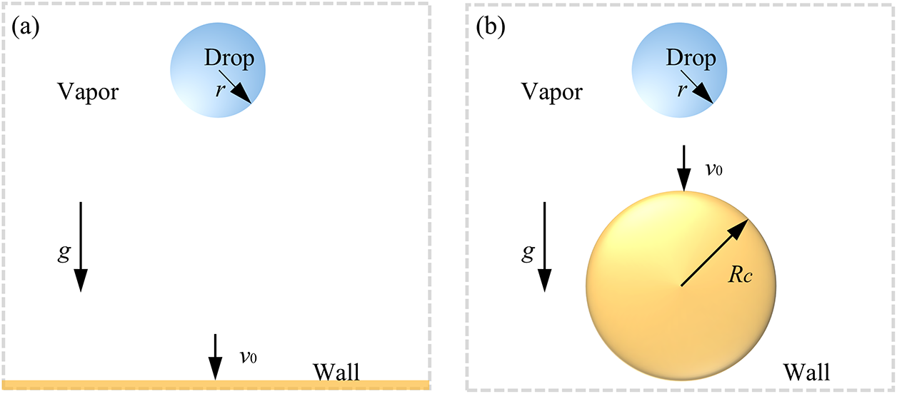
Figure 1: Schematic of the droplet impact on: (a) a plane wall; (b) a curved wall
The droplet is modeled as water with a diameter of 40 lattice length units (lu). Unless otherwise specified, lattice units are adopted throughout the following sections. The initial temperatures of both the droplet and the surrounding vapor are T0 = 0.8Tc, where Tc is the critical temperature. The temperatures of the plane and curved surfaces are maintained constant at Tw. In the present work, a constant cv of 6.0 is adopted. For simplicity, the thermal conductivity λ = ρcvχ, where χ is the thermal diffusivity, is chosen to be proportional to the density ρ with cvχ = 0.028. Then λl/λv = ρl/ρv ≈ 38 [30]. The liquid–vapor density ratio of approximately 38 adopted in the present model is consistent with that used in previous studies [31]. No-slip boundary conditions [32] are imposed on the upper and lower boundaries of the plane, while the curved wall utilizes the Bounce-Back scheme [33]. Periodic boundary conditions are applied to the remaining boundaries.
To ensure the reliability of the numerical results, a mesh independence test was carried out by comparing the spatially averaged density of the droplet under different grid resolutions and time steps, as demonstrated in Fig. 2. By contrast, the coarse grid configuration (150 × 200) demonstrates substantial deviations (0.75%–0.88%). Moreover, further refinement from 300 × 400 to 450 × 600 results in negligible improvement in accuracy while significantly increasing computational cost. Consequently, the 300 × 400 grid resolution was adopted for all subsequent simulations as a reasonable compromise between numerical accuracy and efficiency. For the curved wall simulations, the same grid resolution (300 × 400) was adopted, ensuring identical spatial resolution near the liquid–solid interface. The droplet diameter was resolved by more than 20 lattice nodes, which meets the accuracy requirement reported in previous LBM studies [31,34,35]. Therefore, additional mesh refinement for the curved geometry was deemed unnecessary, as the current grid density sufficiently captures interfacial and thermal gradients.
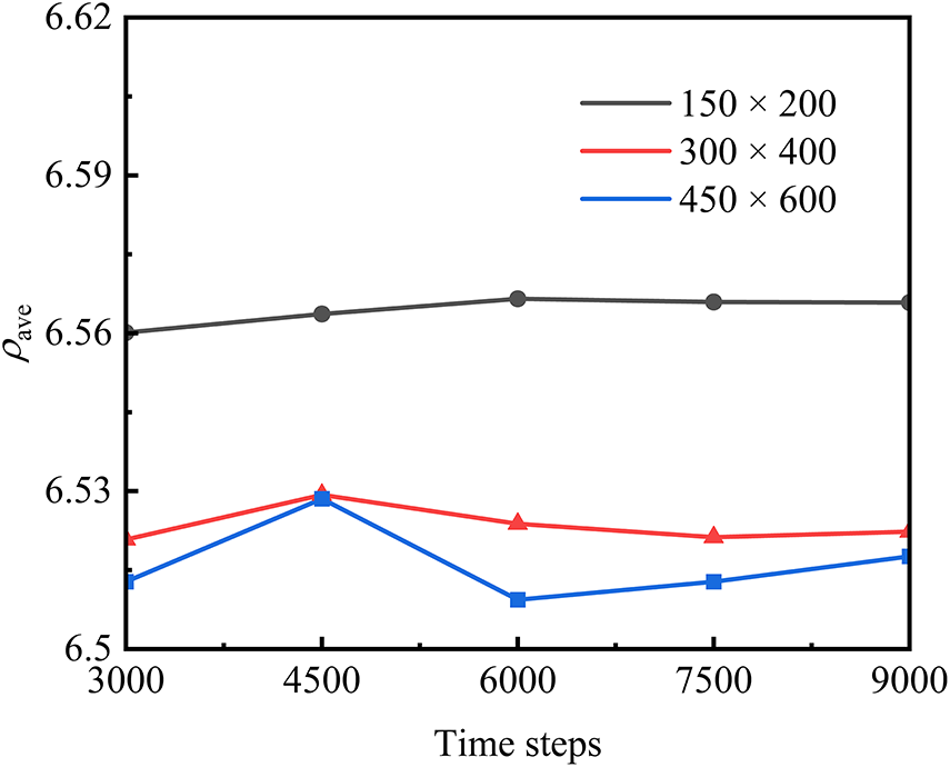
Figure 2: Grid independence test results for the averaged droplet density
2.2 Hybrid Thermal Lattice Boltzmann Method
This work employs the D2Q9 pseudopotential LB model with the MRT collision operator to simulate the dynamics of droplet impact on a solid surface. The MRT LB equation is expressed as follows [30]:
where x and t are the spatial and temporal coordinates, δt is the time step, fi and fieq are the distribution and equilibrium distribution functions in the discrete velocity direction, Fi is the external force term in the discrete velocity direction, M is the orthogonal transformation matrix [36], and ei is the discrete velocity.
Eq. (1) can be decomposed into two steps of “collision” and “streaming” after operation in moment space [30]:
where I is the unit tensor and Λ is the diagonal matrix containing the relaxation time [37]:
the relaxation times are chosen as follows: τρ = τj = τq = 1.0, τζ = 0.8, and τe−1 = 1.1.
In Eq. (2), the distribution moments are defined as m = Mf and meq = Mfeq. m* is transformed back via the inverse transformation M−1 to recover the collision distribution function f*([f1*, f2*…f9*]), and then the streaming step is performed in the velocity space according to Eq. (3), thereby completing the evolution for one time step. The expression for the equilibrium distribution moment meq is [30]:
where ρ is the macroscopic density, and u = (ux, uy) is the macroscopic velocity vector with its components in the x- and y-directions. These macroscopic quantities are calculated from the following equation:
where F is the vector of the resultant forces acting on the system.
To ensure thermodynamic consistency, i.e., the gas–liquid equilibrium density curve obtained through LBM simulations matches the coexistence density curve determined by the Maxwell equal-area rule, an external force term denoted as S is incorporated. The term S is obtained from the transformation of the force F by the matrix M, i.e., S = MF. The expression for this term S is given as follows [38]:
where thermodynamic consistency is controlled by adjusting the parameter ξ in Eq. (8) [39].
The interparticle interaction force is calculated using the Shan-Chen pseudopotential model, which considers only the forces between nearest-neighbor lattice nodes. This force is incorporated into the source term S of the distribution function’s evolution equation, enabling the simulation of spontaneous two-phase interface formation, evolution, and migration. The force Fm is expressed as [40]:
where G is the interaction strength, typically set to ωm are the lattice weights; for the D2Q9 model, these are given as ω(0) = 4/3, ω(1) = 1/3, ω(2) = 1/12 [25]. ψ(x) is the pseudopotential. In this work, a pseudopotential in the square root form is adopted, following the model of He and Peng [41,42]:
where R = 1, b = 2/21. Regarding parameter a, it has been confirmed to be closely related to the gas–liquid two-phase interface [38], and its value is determined based on the specific requirements of the simulation. T and p are the temperature and pressure, respectively. For water, the working fluid, the acentric factor ω is 0.344.
In the pseudopotential model, the external forces acting on lattice nodes are limited to intermolecular interactions. To achieve accurate reproduction of wetting behavior in two-phase flow systems, the incorporation of adhesion forces becomes imperative when the system interacts with solid boundaries. At solid-liquid interfacial fluid nodes, the application of fluid-solid interaction forces is required to achieve contact angle regulation. Following the formulation proposed in the literature [37], the fluid-solid interaction force is expressed as
where s(x + eiδt) denotes the switch function, where s(x + eiδt) = 1 when x + eiδt corresponds to solid nodes and s(x + eiδt) = 0 otherwise. The regulation of contact angle can be achieved by modifying the parameter Gw.
Consideration of solid nodes at the y = 0 layer is required for both fluid-solid interaction force computation and intermolecular interaction force calculation. For these solid nodes where pseudopotentials are undefined, they are treated as ghost fluid nodes with their density assigned to prescribed ghost density values. For flat walls, the fluid density at ghost nodes can be considered equivalent to that at corresponding positions in the y = 2 layer. However, this treatment becomes invalid for complex boundaries, leading us to adopt the approach proposed in [43]:
The wall roughness effect is not considered in this work, as the study focuses on droplet impact over an ideally smooth wall, while the influence of microscale roughness on wettability and heat transfer will be explored in future work.
The total force F acting on the fluid consists of the intermolecular interaction force and the gravitational body force:
where Fm denotes the pseudopotential interaction force between fluid components, as defined in Eq. (9). Fg denotes the gravitational force, calculated as:
where g represents the gravitational acceleration, and ρave indicates the average density across the entire fluid domain.
Ignoring the viscous dissipation term, the entropy equation simplifies to [44]:
where cv is the specific heat at constant volume. Li et al. indicated that the finite-difference method can be directly employed to solve Eq. (13) [30]:
In summary, density ρ and velocity u are obtained through the evolution of the multiphase LB equation. The temperature distribution is determined using the fourth-order Runge-Kutta (RK4) method, and subsequently the pressure distribution can be obtained by the equation of state. The RK4 method is only employed as a higher-order temporal integration scheme for solving the temperature evolution equation, rather than as an independent temperature solver.
To verify the model, thermodynamic consistency is first confirmed. Then, the reliability of the LB model is validated by employing the relationship between the Weber number and the maximum spreading factor of a droplet impacting a solid surface, in conjunction with the D2 law.
2.3.1 Thermodynamic Consistency
Thermodynamic consistency is achieved by adjusting the parameter ξ in Eq. (8). In this section, the P-R equation of state is employed for calculations, with parameter a set to 1/49. The computational domain is configured as a grid of 80 × 80 lattice units. A circular region of radius 20 lattice units at the center of the domain is initialized to the liquid density corresponding to the equilibrium temperature, while the surrounding region is initialized to the gas density corresponding to the same temperature. By varying the equilibrium temperatures, the corresponding gas and liquid density during gas–liquid phase equilibrium at different equilibrium temperatures can be obtained, as shown in Fig. 3. When ξ = 1.21, the simulated coexistence densities closely match the theoretical curve, thereby validating the modified model.
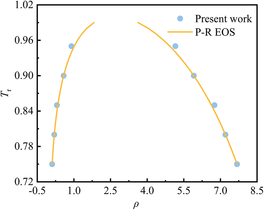
Figure 3: Comparison of simulated coexistence densities with the theoretical curve
2.3.2 Contact Angle Tunability
The contact angles for both plane and curved surfaces are adjusted and validated through the virtual wall method and the formulation of solid-liquid interaction forces. The model parameter a for the plane configuration is set to 1/49, with the computational domain measuring 160 × 60 lattice units. The system is maintained at a constant temperature of 0.8Tc, while the lower wall thickness is defined as 3 lattice units. A droplet is initialized on the surface with an initial radius of 18 lattice units. Zou-He no-slip boundary conditions are applied to the upper/lower walls, with periodic boundaries implemented laterally. Upon reaching equilibrium, the contact angle with the plane is calculated (Fig. 4a). For the curved wall configuration, the model parameter a is set to 1/49, with the computational domain measuring 100 × 120 lattice units. A circular wall with a radius of 28 lattice units is embedded within the computational domain, interfaced with a stationary droplet measuring 20 lattice unit radius. Bounce-back boundary conditions are applied to the curved surface, while periodic boundaries are implemented laterally. Upon reaching equilibrium, the contact angle is calculated and presented in Fig. 4b.
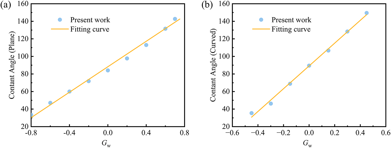
Figure 4: Variation of wall contact angles with Gw: (a) plane wall; (b) curved wall
2.3.3 Relationship between Maximum Spreading Factor and We
When a droplet with an initial radius R0 impacts a non-wetting surface, it rapidly spreads into a pancake-like shape, reaching a maximum diameter Rmax. At this point, the droplet’s kinetic energy is converted into surface energy, achieving the maximum spreading factor βmax, defined as βmax = Rmax/R0.
Biance et al. [45] demonstrated that the maximum spreading factor for a droplet impacting a heated surface can be expressed as βmax~We1/4. We characterize the relative magnitude of the droplet’s inertial force to its surface tension. This dimensionless number has a significant influence on the spreading behavior of droplets and is defined as follows [46]:
where ρl is the liquid density, v0 is the impact velocity, D0 is the initial diameter, and σ is the surface tension coefficient.
This section examines the relationship between the maximum spreading factor βmax and We after droplet impact on a solid surface, validated against experimental and simulation results from existing literature, as shown in Fig. 5a. The fitting results indicate a linear relationship between lg(βmax) and lg(We). The exponent obtained from the simulations in the present work is 0.24, compared to values of 0.23 (simulation, Chatzikyriakou et al. [47]), 0.3 (experiment, Biance et al. [45]), and 0.313 (simulation, Wu et al. [48]).
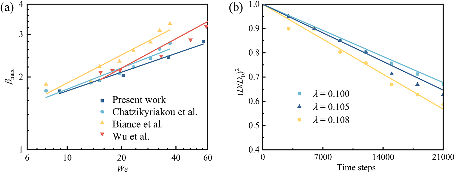
Figure 5: Validation of the model: (a) Relationship between the maximum spreading factor βmax and We; (b) Temporal evolution of the squared droplet diameter
In this section, the gas–liquid phase change model is validated using the D2 law, which states that during droplet evaporation, the square of the droplet diameter radio decreases linearly with time:
where K represents a linear proportionality coefficient.
The computational domain is set to a size of 150 × 150 lattice units. A stationary droplet with an initial diameter (D0) of 40 lu is placed at the center of the domain. The droplet’s saturation temperature and the ambient gas temperature are set to 0.8Tc and 0.9Tc, respectively. Periodic boundaries are applied to all boundaries. As evaporation occurs, the droplet diameter decreases due to interfacial mass transfer, as shown in Fig. 5b. The temporal evolution of the diameter squared follows the theoretical D2 law, which validates the accuracy of the present model.
2.3.5 Verification of the Conservation of Mass
The interaction force and density update in the pseudopotential model ensures global mass conservation, while the latent heat term couples the mass flux from evaporation or condensation to the energy equation. Fig. 6a demonstrates that the total mass variations remained below 0.07% throughout all simulations, validating the accuracy and reliability of the hybrid LBM approach in resolving coupled hydrodynamic and thermal phenomena.
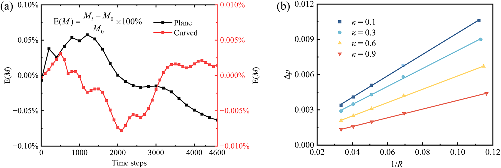
Figure 6: Validation of the model: (a) The variation of relative error (relative initial mass) over time steps; (b) Tunability of surface tension
2.3.6 Tunability of Surface Tension
In previous models, the interfacial surface tension at gas-liquid equilibrium remained nonadjustable. To achieve surface tension regulation independent of density ratio, Li et al. still proceeded from the discrete form of the pressure tensor by introducing a source term C into the collision step of the LB evolution equation, as [43]:
where the expression for source term C is given by [43]:
where,
Tuning parameter κ enables surface tension regulation independent of the density ratio. It should be emphasized that model modifications addressing thermodynamic consistency and surface tension tunability were separately implemented within the MRT-LB framework. Nevertheless, they have been demonstrated to coexist in a unified model, enabling simultaneous achievement of thermodynamic consistency and surface tension regulation independent of density ratio. The temperature of the entire system was maintained at a constant 0.8Tc. Circular droplets with different radii (10, 15, 20, 25, and 30) were initialized at the geometric center of the domain, where the droplet density was set to the equilibrium liquid density at this temperature, while the remaining domain was assigned the equilibrium gas density. The surface tension γ was determined as half the slope of the linear regression fit to the data. Fig. 6b illustrates the relationship between droplet radius and pressure difference at gas-liquid equilibrium under varying κ values, validating the Young-Laplace law through the linear proportionality between the stabilized interfacial pressure difference Δp and the reciprocal of radius 1/R.
3.1 Dynamics and Heat Transfer Analysis of Droplet Impact on a Plane Wall
The typical dynamics of droplet impact on a plane wall are illustrated in Fig. 7. The wall temperature is set to Tw = 1.28Tc. The dimensionless time is defined as τ = tv0/D0, where τ = 0 corresponds to the moment of droplet release. After being released from a height, the droplet acquires momentum due to gravity. At τ = 1.0, the droplet undergoes rapid deformation upon impact, exhibiting a pronounced reduction in height and significant lateral spreading across the heated surface, forming a characteristic hat-shaped morphology. By τ = 2.0, the droplet evolves into a thin, concave liquid film. Surface tension acts to maintain rounded edges while the lamella continues to thin and expand radially. The bottom of the droplet is in direct contact with the heated wall, where intense phase change occurs within the contact region. This vigorous vaporization leads to the nucleation of a vapor cavity at the liquid–solid interface. At τ = 2.5, the outward-directed force at the three-phase contact line drives its continuous advancement, leading to an expansion of the solid–liquid contact area, which enhances vaporization. This is accompanied by the gradual growth of the vapor cavity beneath the droplet. The droplet continues to spread until it attains its maximum diameter. Upon reaching the maximum spreading diameter, the droplet’s kinetic energy is largely dissipated, and surface tension becomes the dominant restoring force. This drives the retraction and, in some cases, partial rebound of the liquid film during τ = 3.0–4.0. Eventually, the droplet attains a steady wetting configuration at τ = 5.0.
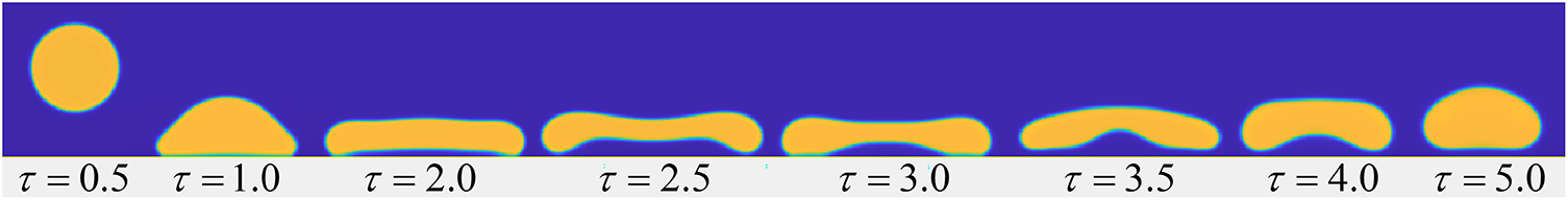
Figure 7: Morphological evolution of a droplet impacting on a plane wall (θ = 66°)
The heat transfer characteristics during droplet impact on a plane surface are further investigated by examining the correspondence of heat flux at various locations and times, as shown in Fig. 8a. The local heat flux is calculated using Fourier’s law [49]:
where λ is the thermal conductivity of the wall.
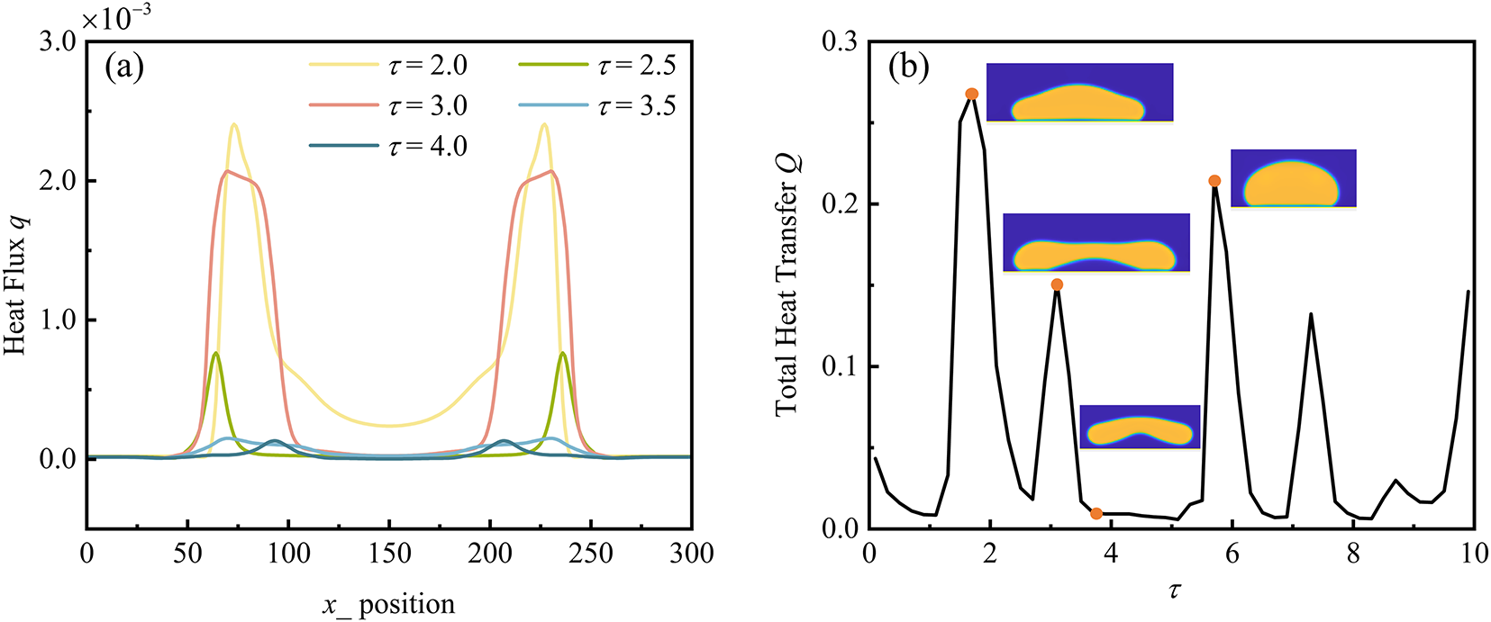
Figure 8: Heat transfer characteristics of droplet impact on a plane wall: (a) Spatial and temporal variation of heat flux; (b) Temporal variation of the total heat transfer
The temporal variation of the total heat transfer is then obtained by integrating the local heat flux on the wall surface. For both plane and curved walls, it is computed as [50]:
where N is the number of grid nodes on the wall and Δxi (or 2πriΔr) represents the local wall segment length (or area element for curved surfaces).
At τ = 2.0, during radial droplet spreading, a minimum in vapor film thickness near the three-phase contact line coincides with a sharp peak in heat flux. A sharp increase in heat flux is observed at this location, whereas it decreases abruptly nearer to the droplet center owing to the greater vapor film thickness, demonstrating an inverse relationship between heat flux density and vapor film thickness. At τ = 2.5, the droplet rebounds, resulting in an increased vapor film thickness and a corresponding reduction in heat flux. By τ = 3.0, the droplet descends and retracts. The vapor film thickness at the droplet center decreases, leading to a subsequent rise in heat flux. However, the peak heat flux is lower than that observed at τ = 2.0. At τ = 3.5 and τ = 4.0, the droplet rebounds again, resulting in a reduction in heat flux. This behavior occurs because heat transfer during droplet impact on the hot wall is dominated by boiling phase change near the three-phase contact line. Once a low-thermal-conductivity vapor layer separates the droplet from the wall, the local heat flux in the contact region undergoes a sharp decline, despite a large temperature difference.
The temporal evolution of the total heat transfer on the surface during the droplet impact process is presented in Fig. 8b. Initially, droplet spreading increases the contact area, leading to enhanced total heat transfer. Subsequently, upon formation of a vapor film between the droplet and the wall, the heat flux decreases due to the significantly lower thermal conductivity of the vapor compared to the liquid. The total heat transfer of the hot wall surface exhibits multiple peaks, arising from the cyclic spreading and rebound processes of the impacting droplet. The plateau regions in the curve correspond to the levitation of the droplet due to the vapor film generated by liquid evaporation, which prevents direct contact with the heated wall. During this phase, heat flux remains low, resulting in poor heat transfer capability.
3.2 Dynamics of Droplet Impact on a Curved Surface
The curved surface is maintained at a constant temperature of Tw = 0.94Tc. The droplet impact process is illustrated in Fig. 9. At τ = 1.5, under the influence of surface tension, the upper portion of the droplet largely maintains its spherical shape, with the flow field remaining unaffected by the curved wall, while the lower part contacts the wall. The droplet then flows downward along the curved surface, forming a defined contact angle at the edge due to surface tension, leading to a continuous increase in contact area. Owing to the small diameter of the curved wall, the droplet spreads to the horizontal centerline by τ = 3.0 and continues spreading afterward. Droplet retraction is minimal, attributed to the combined effects of gravity and surface adhesion.
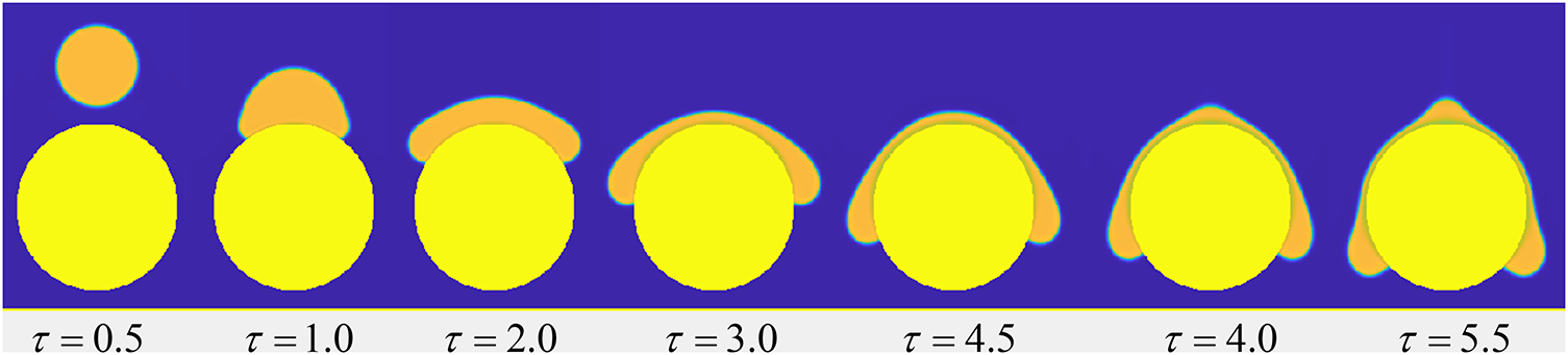
Figure 9: Morphological evolution during droplet impact on a curved surface (θ = 46.3°)
3.3 Factors Influencing Droplet Impact on a Curved Surface
This section investigates the influence of key parameters, including droplet impact velocity, surface wettability, curvature, and gravity, on the impingement dynamics. The dimensionless time τ is defined as zero at the moment of droplet–wall contact. The impact velocity, which determines the initial kinetic energy of the droplet and significantly influences its subsequent behavior, is commonly quantified using the dimensionless Weber number (We). Wettability is governed by the equilibrium between adhesive and cohesive forces: adhesion at the liquid–solid interface promotes droplet spreading, whereas cohesion within the liquid favors a spherical shape to minimize contact area. It is quantified by the static contact angle θ, which categorizes surfaces as hydrophilic (θ < 90°), hydrophobic (θ > 90°), or superhydrophobic (θ > 150°). For curved surfaces, the influence of curvature on impact dynamics is characterized by the dimensionless diameter ratio D* = Dc/D0. In the limiting case where the curvature diameter tends to infinity, the situation becomes equivalent to droplet impact on a plane surface. The role of gravity in such phenomena is typically quantified by the Bond number, Bo = ρlLc2g/σ, where Lc is a characteristic length.
3.3.1 Impact Velocity Effects on Flow and Heat Transfer Characteristics
The time required to reach the maximum spreading diameter and the corresponding maximum spreading factor under various Weber numbers is examined, as shown in Fig. 10a. The time for droplets to achieve the maximum spreading diameter does not vary monotonically with the Weber number. In contrast, the maximum spreading factor increases consistently with the Weber number, measuring approximately 2.05 at We = 0 and reaching 3.29 at We = 80.7. This trend occurs because droplets with higher impact velocities possess greater kinetic energy, which is converted into broader spreading, thereby resulting in a larger maximum spread. Fig. 10b illustrates the angular distribution of near-wall heat flux at τ = 0.85 under varying Weber numbers. A continuous vapor film is formed beneath the droplet, resulting in a concentration of heat flux within the droplet–wall contact region. Near the impact center (φ = 90°), all cases exhibit a pronounced minimum in heat flux, indicating suppressed heat transfer in this area. As the angular position deviates from the center, the heat flux displays a non-monotonic variation characterized by a sharp increase near the three-phase contact line. This phenomenon is primarily due to (i) the greater temperature difference between the wall and the droplet near the three-phase contact line compared to that at the droplet center and (ii) the higher thermal resistance caused by the thicker vapor film in the central region of the wall. An increase in the Weber number significantly alters the structure of the thermal field, broadening the side peaks and shifting them toward lower angular positions (Δφ ≈ ±30°). The corresponding peak areas are significantly larger than those in low-velocity cases at the same dimensionless time, although the maximum heat flux peak remains lower compared to the low-velocity scenarios.
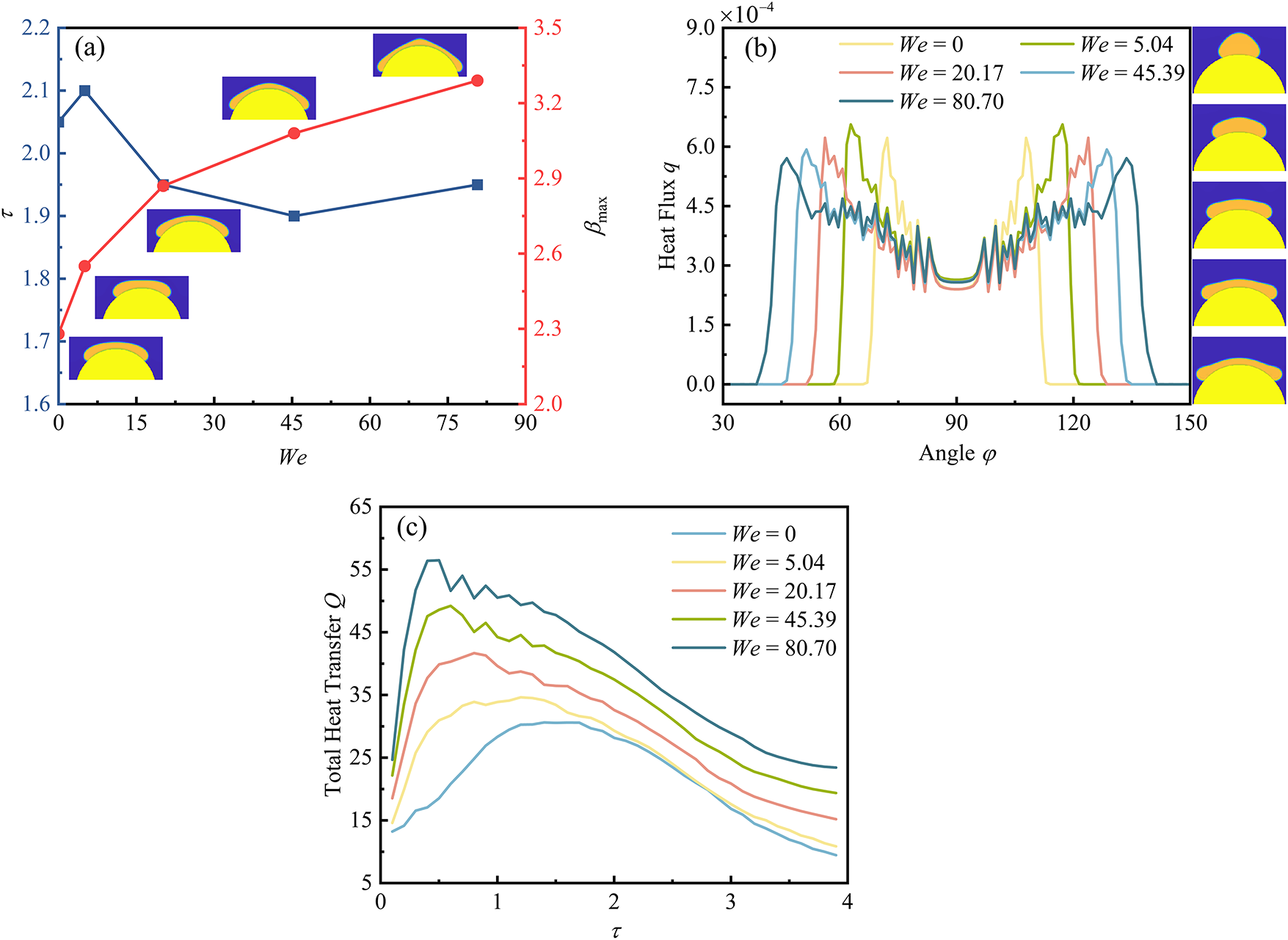
Figure 10: Under different Weber numbers: (a) Time to reach the maximum spreading diameter and spreading factor; (b) Angular heat flux distribution at τ = 0.85; (c) Temporal evolution of total heat transfer (Parameters: D* = 3; Bo = 5.04; θ = 128.3°)
The temporal evolution of the total wall heat flux under different Weber numbers is presented in Fig. 10c. The total heat transfer initially increases with the impact velocity. A distinct peak emerges shortly after the spreading process initiates: at We = 0, the peak value is 30.6; this value increases to 56.47 at We = 80.7, corresponding to an enhancement of approximately 85%. This enhancement can be attributed to the fact that higher-velocity droplets exhibit faster spreading rates and larger maximum spread areas, thereby enhancing the droplet–wall heat transfer.
3.3.2 Influence of Wettability on Flow and Heat Transfer Characteristics
This section presents numerical simulations of droplet impingement on curved surfaces with different surface wettability conditions. As shown in Fig. 11a, the maximum spreading factor shows a slight increase with increasing contact angle, indicating that wettability has a negligible influence on the maximum spreading factor. In contrast, the time required to reach the maximum spreading diameter increases with the contact angle. This difference arises because capillary forces promote spreading on hydrophilic surfaces, whereas they act as a resistance on hydrophobic surfaces, causing the spreading process to rely more heavily on inertial forces. Fig. 11b illustrates that the peak heat flux values for hydrophobic, neutral, and hydrophilic walls are 6.2 × 10⁻⁴, 7.7 × 10⁻⁴, and 8.9 × 10⁻⁴, respectively. The heat flux increases correspondingly with a decreasing contact angle, indicating that enhanced wettability improves heat transfer efficiency. As the angular position shifts from the three-phase contact line toward the impact center, the near-wall fluid temperature rises, leading to a sharp deterioration in heat transfer performance. Concurrently, the differences among the heat flux profiles across surfaces with different wettability gradually diminish. Significant heat flux oscillations are observed within the angular ranges of φ = 56°–82° and φ = 97°–123°. These oscillations occur because these regions lie within the moving three-phase contact line zone, where nanoscale vapor film thickness induces periodic pinning effects and substantial temperature fluctuations.
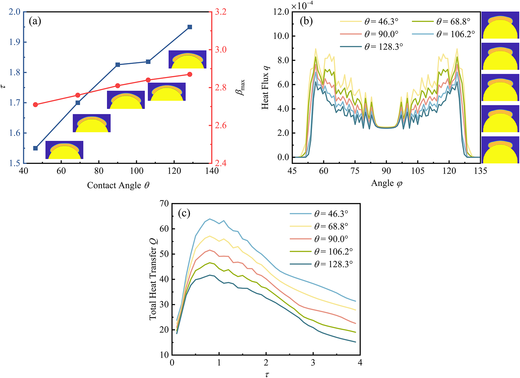
Figure 11: Under different contact angles: (a) Time to reach the maximum spreading diameter and spreading factor; (b) Angular heat flux distribution at τ = 0.85; (c) Temporal evolution of total heat transfer (Parameters: We = 20.17; D* = 3; Bo = 5.04)
The temporal evolution of the total heat transfer during droplet impingement under different contact angles is presented in Fig. 11c. For the hydrophilic surface (θ = 46.3°), the initial peak heat flux attains a value of 63.9 due to the maximum solid–liquid contact area. As θ increases to 128.3°, the initial peak heat flux correspondingly decreases to 41.7. The peak heat flux decreases non-linearly with increasing θ, while the time required to reach the peak remains largely unchanged. For τ > 1.1, the hydrophilic surface displays a sharp decay, whereas the decay rate decelerates significantly for the hydrophobic surface. The total wall heat flux remains predominantly governed by local interfacial heat transfer and instantaneous wetted area, rather than temporal spreading characteristics.
3.3.3 The Effect of Curvature on Flow Characteristics
The time to reach maximum spreading and the maximum spreading factor as functions of the diameter ratio are shown in Fig. 12a. The results show that the maximum spreading factor increases with the diameter ratio, but the rate of this increase gradually diminishes, eventually approaching a constant value. This behavior occurs because, for smaller surface diameters, the maximum spreading factor after droplet impact is influenced not only by physical parameters such as the impact Weber number but also strongly by the geometric characteristics of the surface. As the surface diameter increases beyond a critical value, the resulting change in the diameter ratio (D*) becomes minimal. Hence, the maximum spreading factor is primarily determined by physical parameters. At D* = 1, the time to reach maximum spreading is the shortest, as smaller surface diameters enhance the droplet’s downward spreading tendency. As the surface diameter increases (corresponding to decreasing curvature), the retarding effect of surface tension gradually strengthens, causing the time to reach maximum spreading to generally decrease.
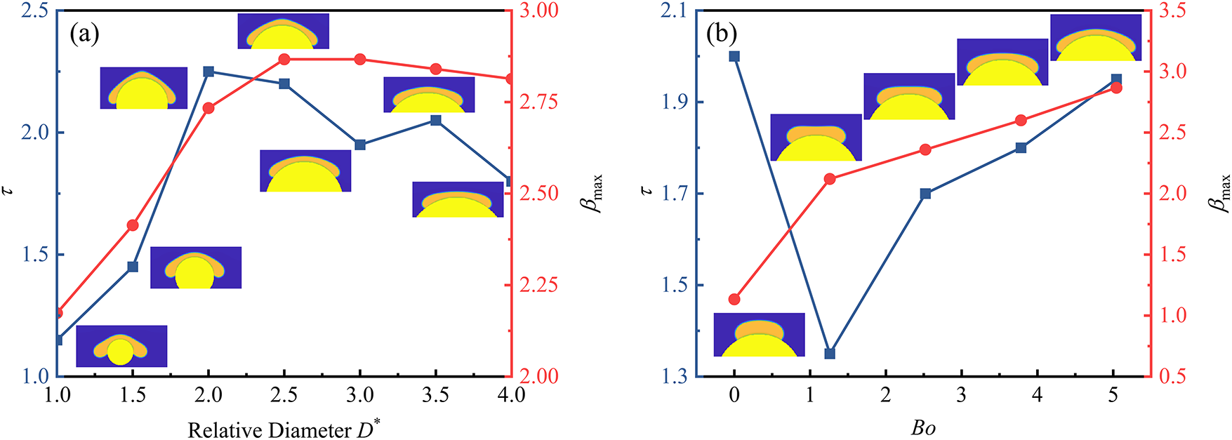
Figure 12: Time to reach the maximum spreading diameter and spreading factor: (a) effect of the dimensionless diameter ratio (We = 20.17; Bo = 5.04; θ = 128.3°); (b) effect of the Bond number (We = 20.17; D* = 3; θ = 128.3°)
3.3.4 Influence of Gravity on Fluid Dynamic Characteristics
Over the considered Bond number range, Fig. 12b demonstrates that the Bond number significantly influences the maximum spreading factor. The value of βmax increases monotonically with increasing Bond number, from 1.13 at Bo = 0 to 2.87 at Bo = 5.04, primarily resulting from the synergistic effect between the initial kinetic energy and gravitational potential energy. However, the rate of this increase continuously decreases, and this enhancement is attributed to the gravitational potential energy driving the radial extension of the liquid film. The dimensionless time τ exhibits a V-shaped trend, decreasing initially and then increasing. At low Bond numbers, surface tension dominates and induces rapid recoiling, whereas at elevated Bond numbers, gravitational forces significantly enhance downward spreading while retarding retraction, thereby prolonging the spreading duration [46,51,52].
This work investigates the hydrodynamic and thermodynamic behavior of droplet impact on hot plane and curved surfaces using a two-phase multi-relaxation-time pseudopotential lattice Boltzmann method (LBM). The main conclusions are obtained as follows:
1. For droplet impact on heated plane walls, spreading, recoil, and rebound phenomena are observed. A sharp local heat flux peak appears near the three-phase contact line, and multiple peaks emerge in the total heat transfer curve.
2. On curved surfaces, droplets flow downward along the wall due to gravity and surface adhesion, leading to the suppression of retraction. The maximum spreading factor increases with the Weber number, diameter ratio, and Bond number, while it slightly increases with contact angle. The time to reach maximum spreading increases with contact angle and exhibits a V-shaped dependence on gravity.
3. The total wall heat flux increases with the Weber number but decreases with the contact angle. Under various Weber numbers, transient heat transfer remains weak at the impact center.
4. As the angular position deviates from the center, the temperature rises sharply near the three-phase contact line. Higher Weber numbers broaden the side peaks of the heat flux and shift them toward lower angular positions. Although the maximum peak value decreases, the area of the heat flux peak for high Weber number droplets is significantly larger than that for low-velocity droplets.
5. As the position moves from the three-phase contact line toward the impact center, the difference in heat flux profiles among surfaces with different wettability gradually diminishes.
Acknowledgement: Not applicable.
Funding Statement: This research was funded by the National Natural Science Foundation of China, grant numbers 52276055 and 52476065.
Author Contributions: The authors confirm contribution to the paper as follows: study conception and design: Xiaoyan Zhuo and Yatao Ren; numerical simulations and data collection: Xiaoyan Zhuo, Yukun Ji and Hong Qi; analysis and interpretation of results: Xiaoyan Zhuo and Xuehui Wang; methodology and model development: Xiaoyan Zhuo, Yukun Ji and Yatao Ren; draft manuscript preparation: Xiaoyan Zhuo and Yatao Ren. All authors reviewed the results and approved the final version of the manuscript.
Availability of Data and Materials: The data that support the findings of this study are available from the corresponding author, Yatao Ren, upon reasonable request.
Ethics Approval: Not applicable.
Conflicts of Interest: The authors declare no conflicts of interest to report regarding the present study.
References
1. Lohse D. Fundamental fluid dynamics challenges in inkjet printing. Annu Rev Fluid Mech. 2022;54(1):349–82. doi:10.1146/annurev-fluid-022321-114001. [Google Scholar] [CrossRef]
2. Liu YC, Farouk T, Savas AJ, Dryer FL, Avedisian CT. On the spherically symmetrical combustion of methyl decanoate droplets and comparisons with detailed numerical modeling. Combust Flame. 2013;160(3):641–55. doi:10.1016/j.combustflame.2012.11.006. [Google Scholar] [CrossRef]
3. Chen X, Du A, Wang X, Yang C, Liang K, Li Z, et al. The effect of vibration on droplet dynamics and heat transfer of spray cooling. Appl Therm Eng. 2024;238:122074. doi:10.1016/j.applthermaleng.2023.122074. [Google Scholar] [CrossRef]
4. Zhang L, Guo Y, Li C, Shen S, Hu S. Numerical study of heat transfer characteristics of horizontal-tube falling film evaporation process coupling condensation inside the tube. Int J Therm Sci. 2025;208:109410. doi:10.1016/j.ijthermalsci.2024.109410. [Google Scholar] [CrossRef]
5. He Q, Xu Y, Zhang F, Jia Y, Du Z, Li G, et al. Preparation methods and research progress of super-hydrophobic anti-icing surface. Adv Colloid Interface Sci. 2024;323:103069. doi:10.1016/j.cis.2023.103069. [Google Scholar] [PubMed] [CrossRef]
6. Xu RN, Wang GY, Jiang PX. Spray cooling on enhanced surfaces: a review of the progress and mechanisms. J Electron Packag. 2022;144(1):010802. [Google Scholar]
7. Jasper WJ, Anand N. A generalized variational approach for predicting contact angles of sessile nano-droplets on both flat and curved surfaces. J Mol Liq. 2019;281:196–203. doi:10.1016/j.molliq.2019.02.039. [Google Scholar] [CrossRef]
8. Liu SL, Shen SQ, Mu XS, Guo YL, Yuan DY. Experimental study on droplet flow of falling film between horizontal tubes. Int J Multiph Flow. 2019;118:10–22. doi:10.1016/j.ijmultiphaseflow.2019.05.008. [Google Scholar] [CrossRef]
9. Zhang H, Ma Y, Hu G, Liu Q. Droplet impaction in nuclear installations and safety analysis: phenomena, findings and approaches. Nucl Eng Des. 2020;366:110757. doi:10.1016/j.nucengdes.2020.110757. [Google Scholar] [CrossRef]
10. Poblador-Ibanez J, Sirignano WA. A volume-of-fluid method for variable-density, two-phase flows at supercritical pressure. Phys Fluids. 2022;34(5):053321. doi:10.1063/5.0086153. [Google Scholar] [CrossRef]
11. Song H, Long T, Cai J, Pan S. A conservative level-set method based on a posterior mass correction with preserving distance property for incompressible multiphase flows simulations. Phys Fluids. 2025;37(9):092109. doi:10.1063/5.0288293. [Google Scholar] [CrossRef]
12. Roccon A, Zonta F, Soldati A. Phase-field modeling of complex interface dynamics in drop-laden turbulence. Phys Rev Fluids. 2023;8(9):090501. doi:10.1103/physrevfluids.8.090501. [Google Scholar] [CrossRef]
13. Succi S. The lattice Boltzmann equation: for fluid dynamics and beyond. Oxford, UK: Oxford University Press; 2001. [Google Scholar]
14. He X, Luo L-S. Theory of the lattice Boltzmann method: from the Boltzmann equation to the lattice Boltzmann equation. Phys Rev E. 1997;56(6):6811–7. doi:10.1103/physreve.56.6811. [Google Scholar] [CrossRef]
15. Lehmann M, Krause MJ, Amati G, Sega M, Harting J, Gekle S. Accuracy and performance of the lattice Boltzmann method with 64-bit, 32-bit, and customized 16-bit number formats. Phys Rev E. 2022;106(1):015308. doi:10.1103/physreve.106.015308. [Google Scholar] [PubMed] [CrossRef]
16. Yao Y, Liu Y, Zhong X, Wen B. Multiphase curved boundary condition in lattice Boltzmann method. Phys Rev E. 2022;106(1):015307. doi:10.1103/physreve.106.015307. [Google Scholar] [PubMed] [CrossRef]
17. Xu Y, Tian L, Bian Q, Guo W, Zhu C, Zhao N. Three-dimensional lattice Boltzmann simulations for droplet impact and freezing on ultra-cold superhydrophobic surfaces. Phys Fluids. 2023;35(12):123321. doi:10.1063/5.0176053. [Google Scholar] [CrossRef]
18. Wen ZX, Li Q, Yu Y, Luo KH. Improved three-dimensional color-gradient lattice Boltzmann model for immiscible two-phase flows. Phys Rev E. 2019;100(2):023301. doi:10.1103/physreve.100.023301. [Google Scholar] [PubMed] [CrossRef]
19. Shan X, Chen H. Lattice Boltzmann model for simulating flows with multiple phases and components. Phys Rev E. 1993;47(3):1815–9. doi:10.1103/physreve.47.1815. [Google Scholar] [PubMed] [CrossRef]
20. Liu H, Wu L, Ba Y, Xi G, Zhang Y. A lattice Boltzmann method for axisymmetric multicomponent flows with high viscosity ratio. J Comput Phys. 2016;327(1):873–93. doi:10.1016/j.jcp.2016.10.007. [Google Scholar] [CrossRef]
21. Li Q, Yu Y, Luo KH. Improved three-dimensional thermal multiphase lattice Boltzmann model for liquid-vapor phase change. Phys Rev E. 2022;105(2):025308. doi:10.1103/physreve.105.025308. [Google Scholar] [PubMed] [CrossRef]
22. Yun S. Controlling the residence time of a bouncing drop with asymmetric shaping. Soft Matter. 2018;14(24):4946–51. doi:10.1039/c8sm00401c. [Google Scholar] [PubMed] [CrossRef]
23. Kim SH, Jiang YY, Kim H. Droplet impact and LFP on wettability and nanostructured surface. Exp Therm Fluid Sci. 2018;99:85–93. doi:10.1016/j.expthermflusci.2018.07.029. [Google Scholar] [CrossRef]
24. Huang X, Zhou L, Du X. Critical contact angle for triggering dynamic Leidenfrost phenomenon at different surface wettability: a molecular dynamics study. J Mol Liq. 2023;382:121982. doi:10.1016/j.molliq.2023.121982. [Google Scholar] [CrossRef]
25. Yang F, Jin H, Dai M. On the spreading behavior of a droplet on a circular cylinder using the lattice Boltzmann method. Chin Phys B. 2024;33(6):064702. doi:10.1088/1674-1056/ad3b7f. [Google Scholar] [CrossRef]
26. Wang J, Wang L, Huang J, Li D. Droplet impact behavior on a hydrophobic plate with a wettability-patterned orifice: a lattice Boltzmann study. Int Commun Heat Mass Transf. 2024;159:108249. doi:10.1016/j.icheatmasstransfer.2024.108249. [Google Scholar] [CrossRef]
27. Huang J, Wang L, Hu J. Numerical investigation of droplet impact dynamics on Janus-textured heated substrates. Phys Fluids. 2023;35(10):107134. doi:10.1063/5.0170171. [Google Scholar] [CrossRef]
28. Wang J, Ouyang S, Chen Y, Dong Q, Wang J, Wang Z. Experimental and LBM simulation study on the effect of bubble departure and bubbles merging on subcooled flow boiling of pure water and surfactant solution. Exp Comput Multiph Flow. 2025;7(4):439–49. doi:10.1007/s42757-024-0215-0. [Google Scholar] [CrossRef]
29. Ouyang S, Wang Z, Wang J, Zeng L, Dong Q, Wang J. Lattice Boltzmann study on sessile droplet deformation and evaporation in the presence of an alternating current electric filed. Int Commun Heat Mass Transf. 2025;167:109303. doi:10.1016/j.icheatmasstransfer.2025.109303. [Google Scholar] [CrossRef]
30. Li Q, Kang QJ, Francois MM, He YL, Luo KH. Lattice Boltzmann modeling of boiling heat transfer: the boiling curve and the effects of wettability. Int J Heat Mass Transf. 2015;85:787–96. doi:10.1016/j.ijheatmasstransfer.2015.01.136. [Google Scholar] [CrossRef]
31. Li Q, Luo KH, Kang Q, He Y, Chen Q, Liu Q. Lattice Boltzmann methods for multiphase flow and phase-change heat transfer. Prog Energy Combust Sci. 2016;52:62–105. doi:10.1016/j.pecs.2015.10.001. [Google Scholar] [CrossRef]
32. Zou Q, He X. On pressure and velocity boundary conditions for the lattice Boltzmann BGK model. Phys Fluids. 1997;9(6):1591–8. doi:10.1063/1.869307. [Google Scholar] [CrossRef]
33. Hu K, Meng J, Zhang H, Gu X-J, Emerson DR, Zhang Y. A comparative study of boundary conditions for lattice Boltzmann simulations of high Reynolds number flows. Comput Fluids. 2017;156(1):1–8. doi:10.1016/j.compfluid.2017.06.008. [Google Scholar] [CrossRef]
34. Wang G, Fei L, Lei T, Wang Q, Luo KH. Droplet impact on a heated porous plate above the Leidenfrost temperature: a lattice Boltzmann study. Phys Fluids. 2022;34(9):093319. doi:10.1063/5.0118079. [Google Scholar] [CrossRef]
35. Albernaz D, Do-Quang M, Amberg G. Multirelaxation-time lattice Boltzmann model for droplet heating and evaporation under forced convection. Phys Rev E. 2015;91(4):043012. doi:10.1103/physreve.91.043012. [Google Scholar] [PubMed] [CrossRef]
36. Lallemand P, Luo LS. Theory of the lattice Boltzmann method: dispersion, dissipation, isotropy, Galilean invariance, and stability. Phys Rev E. 2000;61(6):6546–62. doi:10.1103/physreve.61.6546. [Google Scholar] [PubMed] [CrossRef]
37. Li Q, Luo KH, Kang QJ, Chen Q. Contact angles in the pseudopotential lattice Boltzmann modeling of wetting. Phys Rev E. 2014;90(5):053301. doi:10.1103/physreve.90.053301. [Google Scholar] [PubMed] [CrossRef]
38. Li Q, Luo KH, Li XJ. Lattice Boltzmann modeling of multiphase flows at large density ratio with an improved pseudopotential model. Phys Rev E. 2013;87(5):053301. doi:10.1103/physreve.87.053301. [Google Scholar] [PubMed] [CrossRef]
39. Li Q, Luo KH. Thermodynamic consistency of the pseudopotential lattice Boltzmann model for simulating liquid-vapor flows. Appl Therm Eng. 2014;72(1):56–61. doi:10.1016/j.applthermaleng.2014.03.030. [Google Scholar] [CrossRef]
40. Shan XW. Analysis and reduction of the spurious current in a class of multiphase lattice Boltzmann models. Phys Rev E. 2006;73(4):047701. doi:10.1103/physreve.73.047701. [Google Scholar] [PubMed] [CrossRef]
41. He XY, Doolen GD. Thermodynamic foundations of kinetic theory and Lattice Boltzmann models for multiphase flows. J Stat Phys. 2002;107(1–2):309–28. doi:10.1023/a:1014527108336. [Google Scholar] [CrossRef]
42. Yuan P, Schaefer L. Equations of state in a lattice Boltzmann model. Phys Fluids. 2006;18(4):042101. [Google Scholar]
43. Li Q, Luo K. Achieving tunable surface tension in the pseudopotential lattice Boltzmann modeling of multiphase flows. Phys Rev E. 2013;88(5):053307. doi:10.1103/physreve.88.053307. [Google Scholar] [PubMed] [CrossRef]
44. Hazi G, Markus A. On the bubble departure diameter and release frequency based on numerical simulation results. Int J Heat Mass Transf. 2009;52(5–6):1472–80. doi:10.1016/j.ijheatmasstransfer.2008.09.003. [Google Scholar] [CrossRef]
45. Biance A-L, Chevy F, Clanet C, Lagubeau G, Quere D. On the elasticity of an inertial liquid shock. J Fluid Mech. 2006;554:47–66. doi:10.1017/s0022112006009189. [Google Scholar] [CrossRef]
46. Clanet C, Béguin C, Richard D, Quéré D. Maximal deformation of an impacting drop. J Fluid Mech. 2004;517:199–208. doi:10.1017/s0022112004000904. [Google Scholar] [CrossRef]
47. Chatzikyriakou D, Walker SP, Hewitt GF, Narayanan C, Lakehal D. Comparison of measured and modelled droplet-hot wall interactions. Appl Therm Eng. 2009;29(7):1398–405. doi:10.1016/j.applthermaleng.2008.02.012. [Google Scholar] [CrossRef]
48. Wu S, Zhang C, Chen Y, Shi M. Phase change behavior of the droplet impingement on a hot surface. J Eng Thermophys. 2018;39:174–7. [Google Scholar]
49. Gholijani A, Schlawitschek C, Gambaryan-Roisman T, Stephan P. Heat transfer during drop impingement onto a hot wall: the influence of wall superheat, impact velocity, and drop diameter. Int J Heat Mass Transf. 2020;153(1):119661. doi:10.1016/j.ijheatmasstransfer.2020.119661. [Google Scholar] [CrossRef]
50. Yuan H, He X. Heat flux characteristics of a single droplet splashing on the liquid film obtained with a thermal lattice Boltzmann method. Phys Fluids. 2023;35(7):073331. doi:10.1063/5.0161289. [Google Scholar] [CrossRef]
51. Yarin AL. Drop impact dynamics: splashing, spreading, receding bouncing. Annu Rev Fluid Mech. 2006;38(1):159–92. doi:10.1146/annurev.fluid.38.050304.092144. [Google Scholar] [CrossRef]
52. Liang G, Mudawar I. Review of drop impact on heated walls. Int J Heat Mass Transf. 2017;106:103–26. doi:10.1016/j.ijheatmasstransfer.2016.10.031. [Google Scholar] [CrossRef]
Cite This Article
 Copyright © 2025 The Author(s). Published by Tech Science Press.
This work is licensed under a Creative Commons Attribution 4.0 International License , which permits unrestricted use, distribution, and reproduction in any medium, provided the original work is properly cited.
 Downloads
 Citation Tools