
 Submit a Paper
 Propose a Special lssue
 Open Access
ARTICLE

Scalable and Passive Concentrator Photovoltaics Using a Multi-Focal Pyramidal Array: A Multi-Physics Modeling Approach
Mechanical and Energy Engineering Department, Imam Abdulrahman Bin Faisal University, Dammam, 31441, Saudi Arabia
* Corresponding Author: Mussad Mohammed Al-Zahrani. Email:
(This article belongs to the Special Issue: Advanced Thermal Management and Modeling in Concentrating Photovoltaic Systems)
Frontiers in Heat and Mass Transfer 2025, 23(6), 1883-1905. https://doi.org/10.32604/fhmt.2025.074656
Received 15 October 2025; Accepted 24 November 2025; Issue published 31 December 2025
 View Full Text
 Download PDF
Abstract
Conventional concentrator photovoltaics (CPV) face a persistent trade-off between high efficiency and high cost, driven by expensive multi-junction solar cells and complex active cooling systems. This study presents a computational investigation of a novel Multi-Focal Pyramidal Array (MFPA)-based CPV system designed to overcome this limitation. The MFPA architecture employs a geometrically optimized pyramidal concentrator to distribute concentrated sunlight onto strategically placed, low-cost monocrystalline silicon cells, enabling high efficiency energy capture while passively managing thermal loads. Coupled optical thermal electrical simulations in COMSOL Multiphysics demonstrate a geometric concentration ratio of 120×, with system temperatures maintained below 110°C under standard 1000 W/m2 Direct Normal Irradiance (DNI). Ray tracing confirms 95% optical efficiency and a concentrated light spot radius of 2.48 mm. Compared with conventional CPV designs, the MFPA improves power-per-cost by 25% and reduces tracking requirements by 50% owing to its wide ±15° acceptance angle. These results highlight the MFPA’s potential as a scalable, low-cost, and energy-efficient pathway for expanding solar power generation.Keywords
Nomenclature
| Abbreviation Definition | |
| CPV | Concentrator Photovoltaics |
| MFPA | Multi-Focal Pyramidal Array |
| DNI | Direct Normal Irradiance |
| GC | Geometric Concentration Ratio |
| MJSC | Multi-Junction Solar Cell |
| PWSC | Pyramidal Wall Solar Cell (can be introduced in Section 2 if not already) |
| RMS | Root Mean Square |
| PCM | Phase Change Material |
Energy has been the driving factor of industrial and societal growth for more than a hundred years, and fossil fuels have been the main source of energy for the recent decades. With the depletion of finite fossil fuel reserves and the growing urgency of addressing global warming and climate change, the demand for clean and sustainable renewable energy sources is steadily increasing. Along with these pressures of decarbonization, significant advancements in harnessing natural resources such as solar, wind, and hydro have driven the transition towards sustainable and renewable energy solutions. Solar energy is the most predominant and abundant source of renewable energy [1]. It was first used in 3rd century BC by the Greeks, using mirrors to light torches, and in 7th century BC, magnifying glasses were used to light fires. Solar energy is collected from the sun in two main forms: electricity or heat, typically through photovoltaic or concentrated solar power systems.
Although solar energy is abundant, the early technologies used for harvesting it were not efficient. With the rising demand for electricity in modern times, there has been a growing need for more efficient technologies to harness solar energy. Consequently, solar photovoltaic (PV) systems have undergone significant advancements to enhance their efficiency.
One of the problems concerning PV panel technologies is their low area-efficiency. This limitation led to the creation of Concentrating photovoltaic systems (CPVs), employing lenses and mirrors to focus sunlight on smaller, more efficient solar cells. However, these cells are still not considered cost-effective due to the rarity and high cost of the materials used in their manufacturing. Forcade [2] addressed this cost-efficiency challenge by exploring the use of III-V semiconductor devices. Their study demonstrated that controlled spalling techniques reduce material costs by enabling thinner, high-efficiency semiconductor layers, offering a promising solution for the widespread adoption of high-concentration PV systems.
Mirrors are often used to direct and redirect stray light beams; however, optical losses increase as the number of optics and mirrors increases due to the complexity of ray trajectories and additional reflection losses [3]. They are most found in systems concerned with heat generation or hybrid PV systems, such as concentrated solar power systems with parabolic trough collectors (PTC). Agrawal et al. [4] demonstrated that flat stainless-steel reflectors could enhance photovoltaic performance by up to 25%, reinforcing the potential of reflective materials in optimizing solar energy capture. Some systems make use of multiple lenses and mirrors within one compact system. The optical and system efficiencies of the solar system change depending on the material and geometrical properties of the mirrors and receivers, which in turn affect the system’s concentration ratio. Abbas et al. [5] tested different concentration ratios of 10.38×, 20.76×, and 31.15×, showing that both the concentration ratio and the reflecting material in parabolic dish concentrators significantly impact thermal performance. Kolamroudi et al. [6] explored innovative mirror arrangements in low-concentration PV systems (LCPV), demonstrating that strategically placed low-cost aluminum mirrors can increase power output by nearly 40%. In a similar study, Kolamroudi et al. [7] showed that optimizing mirror angles and configurations in low-concentration PV systems leads to significant improvements in output power, highlighting the versatility of reflective elements in diverse solar setups. Additionally, Bukit et al. [8] investigated the effect of tilt angles in reflective systems, concluding that optimal geometric alignment can enhance solar capture efficiency by up to 18% in residential PV setups.
Conical and pyramidal homogenizers are commonly employed due to their effective light refraction properties. Comparative studies have shown that conical receivers are 2%–10% more efficient than their cylindrical and spherical counterparts. Recent studies in Fresnel lens technology have further enhanced optical performance in solar energy systems. Additionally, efficient optical configurations have been explored for daylighting applications using fiber optics, where systems incorporating Fresnel lenses, infrared filters, and plastic optical fibers demonstrated significant light transmission efficiency and effective thermal regulation [9]. Rashid et al. [10] reviewed Fresnel lenses’ efficiency, highlighting improvements in optical concentration and durability, although their high initial costs remain a limitation for residential use. Building on these advancements, Jost et al. [11] developed innovative fabrication methodologies for high-performance lens arrays, achieving 80% optical efficiency at a concentration of 178×. Similarly, Yi et al. [12] optimized photovoltaic performance using advanced solar concentrator designs, demonstrating significant efficiency improvements under high-concentration conditions. However, Miller & Kurtz [13] highlighted that despite these advancements, the long-term durability of Fresnel lenses remains a concern. Their review pointed out issues of photodegradation and optical performance deterioration due to prolonged exposure to UV radiation and environmental factors, which could affect the reliability of CPV systems over time. Furthermore, Nawawi & Baharom [14] designed a Fresnel lens system with tracking mechanisms, significantly improving solar concentration efficiency, a concept aligned with our proposed hybrid pyramidal design. However, their study does not address the thermal challenges arising from concentrated sunlight, leaving a critical gap in thermal management solutions. Kopalakrishnaswami et al. [15] conducted experiments on a conical cavity receiver for a parabolic dish collector system and found that thermal efficiency was heavily dependent on direct irradiance with a value that does not exceed 75%. A fixed Fresnel lens-conical cavity receiver solar system was experimentally investigated to examine the system’s optical performance with and without glass covers. The results showed that optical efficiency increased without the glass covers by 13% [16]. Additionally, CPV technologies implement tracking systems to maximize efficiency and to ensure coverage of more incident sunlight.
Most modern solar systems include a tracking system, which massively increases the overall system efficiency [17]. These systems aim to maximize the exposure of the solar receiver to sunlight by mechanical or electrical means. Tracking can be done on one, two, or three axis, although dual-axis tracking is more efficient [1]. Bunthof et al. [18] highlighted that CPV solar cells are particularly sensitive to the angle of illumination, with even slight deviations from the optimal angle resulting in significant efficiency losses. This finding underscores the importance of precise tracking mechanisms in CPV systems, a feature central to the current hybrid pyramidal design. Hutauruk et al. [19] demonstrated that combining Fresnel lenses with dual-axis auto-tracking systems increased electricity production by 15%, highlighting the synergy between optical concentration and dynamic sun positioning. This approach aligns with our hybrid pyramidal design, which seeks to integrate both optical and mechanical enhancements to maximize energy output. Most industrial solar systems use a dual-axis tracking system. However, for residential and urban uses, a single-axis tracker is more viable due to space and cost restrictions.
The automated shape-transformable self-solar-tracking cell proved its usability in residential applications as previously mentioned in [20]. This system doesn’t rely on machinery for tracking, rather utilizes a shape-transformable 3D solar cell array, which can bend and change shape based on the sun’s position. These self-solar-tracking cell arrays provided 60% more electricity than conventional solar tracking systems [20]. Another tracking technique used in CPV (Concentrated Photovoltaic) systems is Tracking-Integrated CPV (TI-CPV), which incorporates various tracking methods. One such method, known as micro-tracking, was introduced by [21]. In this approach, only a glass sheet, positioned between refractive and reflective optics, is moved to align the focal spots with the solar cells. The glass sheet, containing an array of lenses, slides laterally using a ball-and-guide mechanism to maintain proper alignment with the concentrated sunlight. On one hand, mechanical tracking systems can be cheaper than their electrical counterparts. However, electrical tracking systems are easier to install, control, and integrate. Another important aspect is that solar cells may reach extremely high temperatures and burn due to the constant contact with sunlight and the effects of lenses. As a result, the integration of effective cooling systems has become essential.
Other designs have an integrated cooling system, increasing their electrical efficiency [22]. For instance, Wang et al. [23] introduced Flat Spiral Pulsating Heat Pipes (FS-PPHP) as an innovative cooling solution for high-concentration PV systems, demonstrating their ability to maintain optimal temperatures even under intense solar concentration. Similarly, Jatau et al. [24] developed a centralized square array heat sink that effectively manages heat in High-Concentration Photovoltaic (HCPV) systems, maintaining cell temperatures under 110°C. While both studies emphasize thermal management, they do not integrate optical concentration technologies like Fresnel lenses. Additionally, Abd-Elhady et al. [25] reviewed cutting-edge cooling techniques, focusing on the application of nanofluids and phase change materials (PCMs) in photovoltaic systems. Their research highlighted how these methods enhance thermal management in high-concentration PV setups. In line with this, Kumar et al. [26] demonstrated that nanofluid-based cooling systems, when optimized for flow rate and temperature, significantly improved the thermal performance of PV modules under varying climate conditions. These findings emphasize the potential of integrating advanced cooling solutions in CPV systems to maintain optimal operating temperatures while enhancing electrical efficiency.
In some cases, a cooling system is required to ensure proper operation of the system because the solar cells reach high temperatures leading to thermal mechanical effect [27]. Cooling is accomplished using a variety of methods. Heat sink systems, such as heat pipe and fan systems, are among the most popular cooling techniques. Obaid et al. [28] investigated a PV system with different cooling methods and their effect on cell performance. Through different values of irradiance, the solar cells were subjected to tests of efficiency under the different values of irradiance. Specifically, at an irradiance level of 4200 W/m2, systems utilizing heat sinks and fans demonstrated a 10% increase in efficiency compared to non-cooled systems.
General use of cooling mechanism is through either active or passive heat sinks. Different materials are utilized to optimize the performance of the heat sink. Aluminum and copper are the most commonly used materials for heat sinks. Aluminum heat sinks are generally cheaper and more efficient, whereas copper heat sinks are easier to shape [29].
Natural or forced convection heat transfer products can increase solar cell electrical performance by 16%. Soliman et al. [27] and AlFalah et al. [30] tested the maximum temperature reached in a solar cell with flat plate heat sink with natural convection in comparison to forced convection exhibiting that forced convection with a flat plate heat sink was much more effective in dropping the cell temperature. As solar energy is concentrated into a smaller spot with the use of optics, the need for cooling increases, therefore, a flat plate heat sink may not be sufficient. AlFalah et al. [30] studied and optimized a combined heat sink system that utilizes both fins and pins to maximize cooling.
Water cooling is an active cooling mechanism [22,31]. Ibrahim et al. [31] demonstrated the effectiveness of back sheet cooling combined with pulsating water flow, using water as the working fluid circulating beneath the solar cells. Pulsating flow allows for more control over the flow rate of coolant and heat transferred, and it can reduce the usage of working fluid. On the other hand, pulsating flow introduces complications into the system, such as control valves, microcontrollers, sensors, and channel vibrations due to pulsations [31]. Heat pipe cooling involves the use of channels on the backside of the solar cells, through which a coolant flows to dissipate heat. These channels can be of semicircular, semi-elliptical, triangular, or rectangular cross section. Maatallah et al. [32] showed that triangular and semielliptical channels offer the most heat transferred to the working fluid, while conventional circular pipes performed worse. Again they [32] observed that the triangular channel achieved a back sheet temperature of 333.1 K and a maximum thermal energy rate of 11.834 kW, while semicircular channels reached back sheet temperatures as high as 344.76 K. Some cooling methods try to maximize energy production by utilizing the energy dissipated as heat. As a result, hybrid solar systems were developed to optimize performance. In a hybrid heat pipe CPV-T system, which merges CPV and CSP systems, a solar cell was operating at 28% efficiency without secondary optics [33].
While efficiency improvements are critical, Shanks et al. [34] emphasized that CPV systems face long-term challenges in maintaining optical performance due to environmental exposure and material degradation, highlighting the need for more durable system designs. Recent studies in solar technology have expanded their applicability beyond conventional power generation. For instance, Aziznezhad et al. [35] demonstrated how advancements in photovoltaic efficiency can be leveraged in agrivoltaics systems, optimizing both energy production and agricultural productivity. Such diversified applications highlight the importance of continuous improvements in CPV technologies, particularly in enhancing efficiency and thermal management.
This paper addresses a critical research gap in concentrating photovoltaic (CPV) systems by tackling the persistent trade-off between the high efficiency and high cost. While CPV technologies leverage optical concentrators to achieve superior efficiency, their widespread adoption is hindered by expensive materials (e.g., III–V semiconductors) and complex cooling requirements. The novelty of this work lies in its hybrid pyramidal design, which integrates a cost-effective Fresnel lens with monocrystalline silicon solar cells, strategically arranged to optimize light concentration and thermal management. The proposed Multi-Focal Pyramidal Array (MFPA)-Based CPV has a unique optical design since it employs a geometrically optimized pyramidal concentrator that channels sunlight along a multi-stage focal path, where single-junction solar cells are strategically placed at key focal locations. This tiered arrangement allows for staggered energy harvesting based on light intensity distribution, enhancing both power output and thermal management. By computing simulating different configurations to balance irradiance distribution and heat dissipation, the study aims to decouple efficiency from cost, demonstrating that safe operation can be achieved without expensive components. The primary objectives include optimizing geometric concentration ratios, validating thermal performance under varying irradiance, and proposing scalable cooling solutions promoting CPV toward practical, affordable high-efficiency systems.
2 Design of a Hybrid System’s Shape
The design is aiming to configure single-junction solar cells on the pyramidal walls to maximize the power output of the concentrated photovoltaic systems and the overall system efficiency. In the traditional CPV designs, especially for geometric concentration ratio exceeding
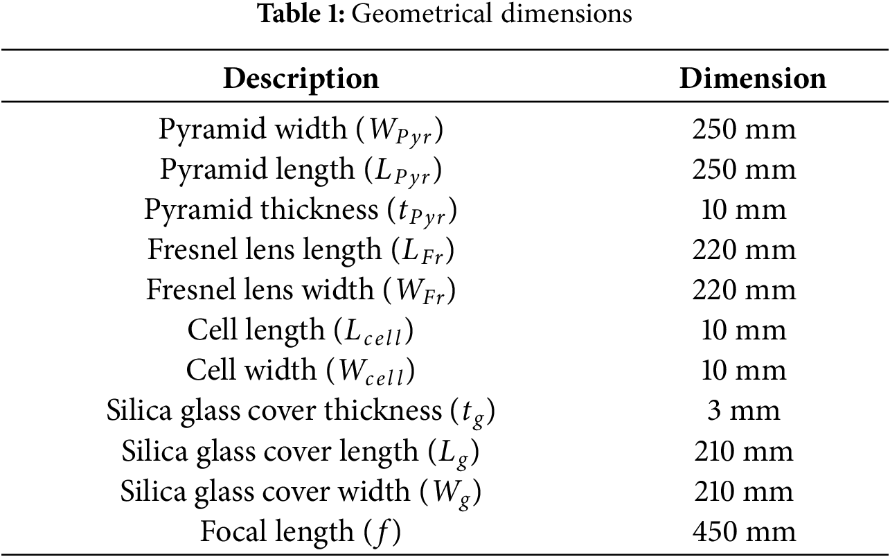
The MFPA is innovative for multiple technical advantages; first it has a unique optical geometry since the pyramidal shape is not merely a structural choice but an optical and thermal optimization tool. The inclined walls act as light guides, redirecting rays that would otherwise diverge after the focal point. Moreover, the extended focal zone allows for multiple energy extraction points, unlike conventional CPV systems that waste divergent rays. Secondly, the Aluminum was shaped into a pyramid of 3 mm thickness and 250 mm width and 404 mm height ensuring sufficient focal length for distributed solar cells. The use of 3 mm-thick aluminum ensures high thermal conductivity for passive cooling while maintaining structural rigidity. All the pyramid walls are aligned with a Fresnel lens 250 mm × 250 mm, and 10 mm × 10 mm solar cells, as shown in Fig. 1. The solar cells’ dimensions are small enough to fit densely on the pyramid walls and minimize interconnection losses. Figs. 1 and 2 illustrate the overall configuration of the system, and all critical geometrical dimensions used in numerical modeling are listed in Table 1.
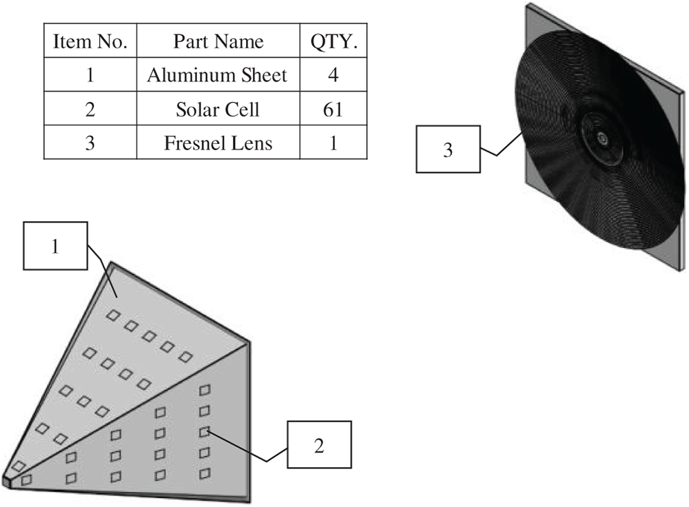
Figure 1: Optical design and sub-components of the Multi-Focal Pyramidal Array (MFPA)-Based CPV system

Figure 2: Solar cells distribution
Materials Properties
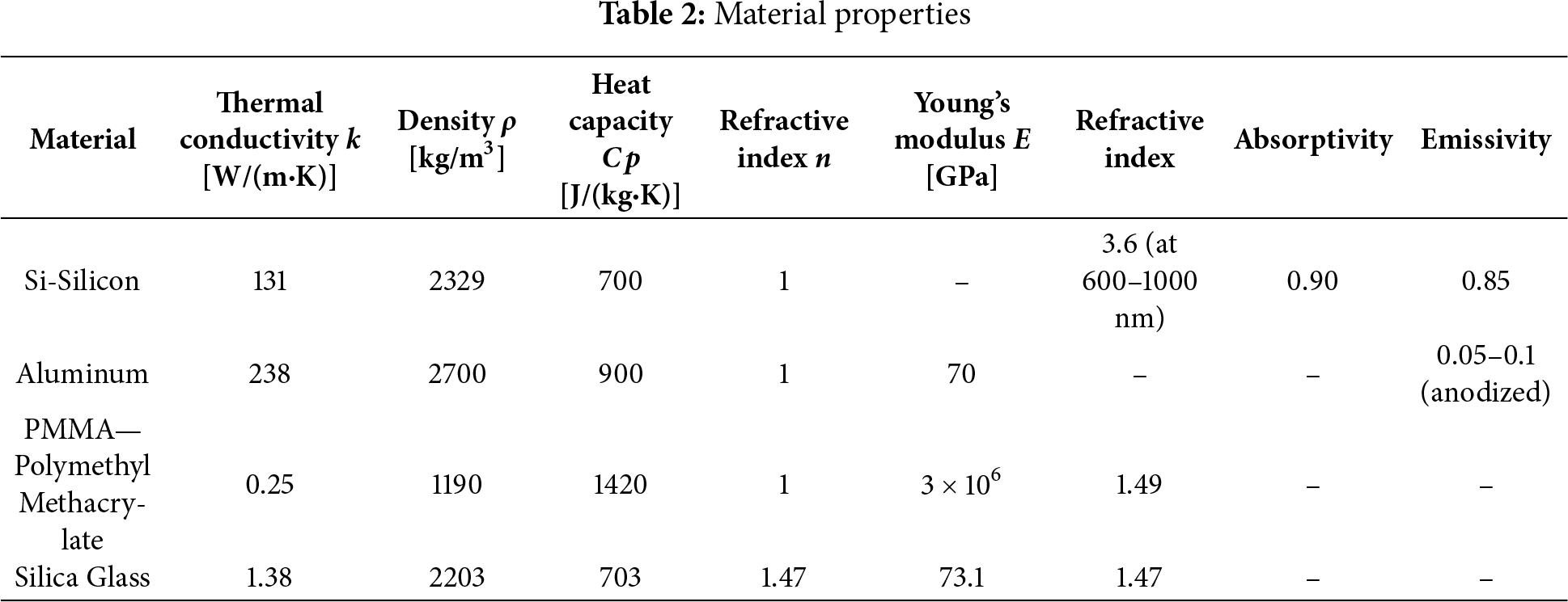
The choice of materials for the CPV was guided by a balanced consideration of four key aspects: ease of procurement, adaptability to design, functional performance, and economic feasibility. These factors were incorporated into the selection methodology to ensure the proposed system could be both practical and scalable.
Firstly, material availability in the commercial market was treated as a primary constraint. Opting for widely available materials not only improves logistics but also supports long-term implementation. Due to the non-conventional pyramid structure of the system, materials that allow greater manufacturability and design adaptability were prioritized to simplify the prototyping process. Performance capabilities of the materials were also assessed, including their optical transparency, thermal resistance, and structural durability under concentrated solar exposure. These attributes were necessary to support the dual functions of light concentration and heat management. Lastly, cost-efficiency was considered to ensure the design remains accessible without compromising quality. A detailed summary of the selected materials and their corresponding properties is provided in Table 2.
3 Formulation of Multi-Physics Problem
3.1 Optical Model: Fresnel Lens Design and Theory
A Fresnel lens is an optical component designed to concentrate light, achieving the functionality of a conventional lens but with significantly reduced mass and volume. This is accomplished by segmenting a standard lens into a series of concentric annular sections, each functioning as an individual refracting surface. Such a design is particularly advantageous in solar energy applications, where large aperture lenses are required to gather substantial sunlight.
The Fresnel lens reduces material usage by dividing the lens into multiple concentric sections, each approximating the curvature of a traditional lens [36]. This segmentation allows the lens to be much thinner and lighter, making it ideal for applications like solar concentration. The design involves calculating the optimal angles and positions of these sections to ensure that incoming parallel light rays are focused to a common point.
The operation of a Fresnel lens is governed by the principles of refraction, as described by Snell’s Law [37]:
where,
Each section of the Fresnel lens is designed to bend light rays toward a common focal point, adhering to Snell’s Law. The lens’s ability to concentrate light is quantified by the Geometric Concentration Ratio (GC):
where,
To develop a more precise ray-tracing model, Hamiltonian optics is incorporated, offering a rigorous framework for analyzing light propagation in complex optical systems [38].
In Hamiltonian optics, the motion of light rays follows Hamilton’s Equations:
here,
The thermal behavior of the CPV system is governed by three primary modes of heat transfer: radiation, convection, and conduction. The Fresnel lens focuses incoming sunlight onto multiple photovoltaic (PV) cells, leading to high irradiance concentration at the pyramidal tip, where the heat generation is most significant.
This thermal energy must be effectively dissipated to prevent efficiency loss and potential thermal degradation of the PV cells. The heat transfer mechanisms are modeled using COMSOL Multiphysics to evaluate system performance and assess simulative and optimal cooling strategies.
3.2.1 Governing Equations Governing Heat Transfer Equations
The fundamental equation governing heat transfer in a solid medium, such as PV cells, heat sinks, and the mounting structure, is derived from the principle of energy conservation and can be expressed as:
where
3.2.2 Heat Transfer Mechanisms in CPV
In the presence of high irradiance from the Fresnel lens, the dominant modes of heat transfer must be evaluated and mitigated effectively.
Radiative heat transfer plays a significant role due to the elevated operational temperatures of PV cells and structural components. Stefan-Boltzmann law governs the net radiative heat loss:
where
Convective heat transfer occurs at the interface between the solar cell surface and the surrounding air. The rate of heat transfer via convection is defined by Newton’s Law of Cooling:
where
Heat conduction within the solid materials of the CPV system follows Fourier’s Law [39], given as:
where,
3.2.3 Thermal Energy Input from Solar Concentration
The CPV system receives concentrated solar energy at the photovoltaic solar cells. This concentrated energy input can be expressed as the boundary incident power:
where,
However, for the thermal model, the boundary heat source (
where
In photovoltaic systems, the Fill Factor (FF) is a crucial parameter that quantifies the quality of the solar cell’s current-voltage (I–V) characteristics. It is defined as the ratio of the maximum obtainable power (
This relationship indicates how closely the solar cell’s performance approaches its theoretical maximum power output. A higher fill factor signifies a more efficient solar cell with lower internal resistive losses.
3.4 Electrical Performance Model
The electrical power output of the solar cells is calculated based on the optically simulated irradiance and the thermally simulated cell temperature. The temperature-dependent electrical efficiency (
where
where
Fig. 3 presents the boundary conditions setup used for the coupled optical-thermal simulation of the MFPA-Based CPV system. In part (a), the optical model configuration is shown, where the Fresnel lens is defined as an illuminated surface exposed to 1500 rays of solar radiation with an irradiance of 1000 W/m2. The front surfaces of both the center and sidewall cells are treated as freezing boundaries, allowing the simulation to deposit the incoming ray power directly onto these surfaces for accurate energy transfer. Part (b) illustrates the thermal model setup, where the center cell is assigned a heat boundary source, and the surrounding sidewall surfaces are set as freezing surfaces receiving ray-deposited power. These boundary conditions ensure a realistic coupling between the radiative input and heat distribution within the system.

Figure 3: Boundary condition settings for coupled optical-thermal analysis. (a) Optical model configuration; (b) Thermal model setup
Validation of the simulated thermal field is performed through a comparative analysis with experimentally recorded temperature data from the literature [40]. While the optical layout and cell configuration differ, both systems involve a silicon-based photovoltaic receiver subjected to concentrated solar flux, allowing for a relevant comparison of focal zone thermal characteristics. This approach validates the core thermal physics implemented in our model. Fig. 4 presents a comparative visualization of the peak temperature distribution. The left image corresponds to the present MFPA simulation, conducted under an incident irradiance of 800 W/m2 and ambient temperature of 50°C, predicting a maximum temperature of approximately 162°C near the geometric focal convergence. The right image is an infrared (IR) thermal image adapted from the experimental work of Ahmed et al. [40], showing a system operating under concentrated flux where a recorded maximum temperature of 156.8°C was achieved.

Figure 4: (a) Simulated MFPA temperature (max: 162°C); (b) Experimental IR image (max: 156.8°C) from Ahmed et al. [40]
A quantitative analysis of the thermal profiles shows that both systems exhibit a central hotspot exceeding 150°C surrounded by steep radial temperature gradients. The relative difference in peak temperature (∼3.3%) is reasonable given the substantial differences in system architecture (single cell vs. distributed cells), boundary conditions (forced cooling vs. passive dissipation), and ambient temperature. This consistency in the thermal response under concentrated flux supports the physical realism of the MFPA thermal simulation results.
Therefore, the strong agreement in thermal profiles serves as a robust, system-level validation that the underlying optical model accurately predicts the magnitude and spatial distribution of the concentrated solar energy, which is the primary input for the thermal simulation.
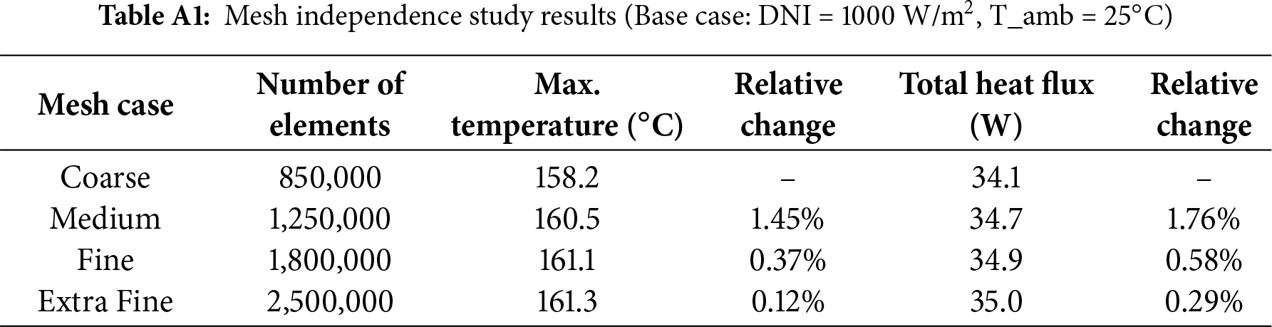
A mesh independence study was conducted to ensure the accuracy of numerical results while optimizing computational resources. The computational domain was discretized using an unstructured tetrahedral mesh, with finer elements applied in regions of high gradients, such as near the solar cells and the focal zone. The mesh quality was assessed, achieving an average element quality of 0.85 and a minimum element quality of 0.15, which are within acceptable limits for COMSOL simulations.
The study was performed by progressively refining the mesh and monitoring the maximum temperature at the focal point and the total heat flux on the primary solar cell. The results, summarized in Table A1 (see Appendix A), showed that the solution converged at a mesh consisting of approximately 1.8 million elements. The relative change in both key parameters was less than 1% upon further refinement to 2.5 million elements. Therefore, the mesh with ~1.8 million elements was selected for all subsequent simulations.
Fig. 5 shows the spot diagram generated by the Fresnel lens, illustrating the convergence of light rays at the focal region. The simulation setup demonstrates how the incident rays are concentrated along the optical axis, with the spot size formed at a distance of approximately 0.8 m below the lens. The inset figure presents the spot diagram at the focal plane, where the color map indicates the normalized ray intensity distribution. It is observed that most of the rays are clustered near the center, forming a circularly symmetric pattern, which confirms the good focusing capability of the Fresnel lens. The root-mean-square (RMS) radius of the spot was calculated to be 2.48 mm, ensuring efficient light collection within the numerical aperture of the subsequent optical stage.

Figure 5: Spot diagram of the Fresnel lens
Fig. 6 shows the heat boundary source distribution at three different axial distances from the Fresnel lens focal plane: (a) 0 cm, (b) 30 cm, and (c) 60 cm. These positions correspond to the focal point, a moderately defocused plane, and a significantly early convergence plane, respectively. The analysis was conducted to assess the variation in thermal energy concentration as a function of distance from the optimized focal location. As shown in Fig. 5a, the highest boundary heat source was recorded when the receiving surface was placed exactly at the focal point (0 cm). A strong and compact heat spot is observed at the center, with a peak intensity of approximately 3.62 × 10⁶ W/m2, confirming optimal focusing and energy coupling. In Fig. 5b, when the surface is shifted 30 cm away from the focal point, the heat distribution becomes noticeably broader and less intense. The maximum heat source drops to 4.75 × 10⁵ W/m2, reflecting a substantial reduction in concentrated energy. The rays are less aligned with the core acceptance region of the fiber optics, leading to increased optical loss. Further deviation, as depicted in Fig. 5c (60 cm from the focal point), results in a weak and widely scattered thermal footprint, with the heat source peak decreasing further to around 4.75 × 10⁵ W/m2. The absence of a defined focal zone indicates significant energy dispersion due to early interception of the converging rays.
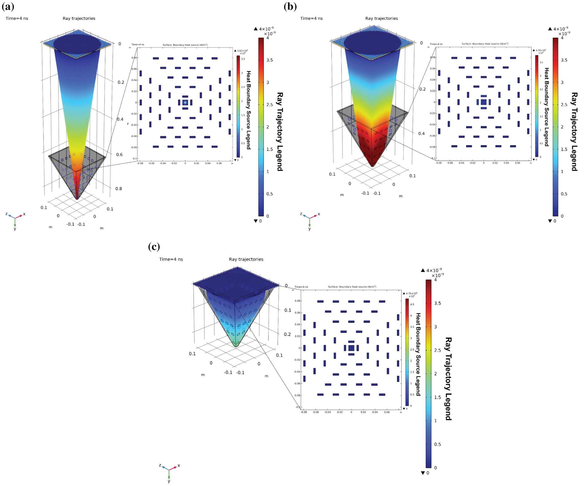
Figure 6: Boundary heat source distribution at different axial distances from the Fresnel lens focal point: (a) 0 cm (at the focal plane); (b) 30 cm; (c) 60 cm
In Fig. 7, when the receiving surface is positioned exactly at the focal plane, a sharp and highly concentrated temperature zone is observed at the lower tip of the concentrator, with a maximum temperature reaching approximately 161°C. This demonstrates that the optical rays are fully focused at this location, resulting in a strong localized thermal impact. At 30 cm above the focal plane, the peak temperature is significantly reduced to 40.2°C, and the heat distribution appears broader and less concentrated. The rays begin to diverge before reaching this height, leading to reduced power density and thermal intensity. At 60 cm, the thermal effect becomes even more dispersed, with a maximum temperature of only 26.6°C. The heat is more uniformly distributed, and no prominent hotspot is visible. This confirms that the rays are intercepted prematurely before reaching their convergence, resulting in minimal thermal accumulation. These results confirm that the maximum temperature is obtained when the receiver is placed at the focal point of the Fresnel lens. Any misalignment in the vertical direction leads to a significant drop in temperature due to energy dispersion. Therefore, accurate positioning at the focal height is essential to ensure high optical-to-thermal conversion efficiency in daylighting applications.

Figure 7: Temperature distribution within the concentrator at different axial distances from the focal plane: at the focal height (left), 30 cm above (middle), and 60 cm above (right)
The maximum temperature at the geometric focal point increases linearly with ambient temperature across all considered DNI levels, as presented in Fig. 8. It is critical to clarify that this high-temperature region (exceeding 160°C) is the location of peak flux concentration, and the photovoltaic cells are not placed here. The strategically positioned cells on the pyramid walls operate at significantly lower and safer temperatures, as shown in subsequent results. At a constant DNI, the rise in ambient temperature leads to a proportional increase in the thermal response of the system. For instance, at 1000 W/m2, the maximum focal point temperature rises from approximately 165°C at 25°C ambient to over 210°C at 50°C. A similar trend is observed for other irradiance levels, with lower DNI values resulting in proportionally lower peak temperatures. This linear behavior indicates that radiative input and ambient conditions act cumulatively, influencing the thermal loading at the focal region. These results underline the necessity of thermal stability and heat dissipation considerations, particularly under high DNI and elevated ambient conditions where material limits and system efficiency may be challenged.

Figure 8: Influence of ambient temperature on the maximum temperature at the focal point for different DNI levels
While the focal point can reach temperatures above 160°C (Fig. 7), the strategically placed photovoltaic cells on the pyramid walls operate below 110°C, as confirmed by the detailed temperature distributions shown in Fig. A1 (see Appendix A). This is a critical advantage, as prolonged operation of silicon solar cells above 120°C significantly accelerates degradation and shortens lifespan [13,27].
The variation in maximum temperature measured 30 cm above the focal plane is illustrated in Fig. 9 for two levels of direct normal irradiance (DNI): 600 and 1000 W/m2. A linear relationship between ambient temperature and system temperature is evident at this height. At 600 W/m2, the maximum temperature increases from approximately 37°C at 25°C ambient to around 62°C at 50°C. At 1000 W/m2, the temperature rises from 45°C to nearly 70°C across the same ambient range. Compared to the focal point values in Fig. 7, the temperatures at this elevation are significantly lower, indicating a strong thermal gradient along the optical axis. These results emphasize the diminishing thermal intensity with distance from the focal region and reinforce the importance of component placement and thermal shielding in system design to ensure safe and efficient operation.

Figure 9: Influence of ambient temperature on the maximum temperature at the focal point for different DNI levels for focal plane 30 cm above
Fig. 10 shows the relationship between ambient temperature and the maximum temperature recorded at 60 cm above the focal point for two levels of Direct Normal Irradiance (DNI): 600 and 1000 W/m2. A clear linear trend is observed in both cases, where increasing ambient temperature leads to a proportional rise in the system’s thermal response. At 600 W/m2, the maximum temperature increases from approximately 28.8°C at 25°C ambient to 53.7°C at 50°C. Under 1000 W/m2, the corresponding increase is from 31.4°C to 56.3°C. While both irradiance levels show similar trends, the higher DNI results in consistently greater thermal loads. The relatively lower temperatures at this elevation, compared to the focal point, confirm the presence of a strong axial thermal gradient. These findings underscore the importance of incorporating vertical temperature distribution into system design, particularly for components positioned away from the focal region.
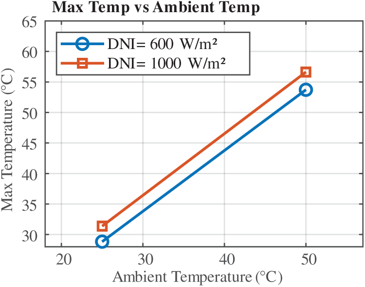
Figure 10: Influence of ambient temperature on the maximum temperature at the focal point for different DNI levels for focal plane 60 cm above
The simulated temperature distributions at horizontal planes located 30 cm and 60 cm above the focal region are illustrated in Figs. A2 and A3, respectively, under varying ambient temperatures and DNI levels. These visualizations complement the quantitative trends shown in Figs. 9 and 10, providing further insight into the spatial thermal behavior at elevated positions.
Fig. 11 illustrates the optical concentration (OC) values recorded by the center and sidewall cells at various vertical distances from the focal point under a fixed DNI of 1000 W/m2. At 0 cm, the center cell achieves the maximum OC of 365 suns, while the sidewall receives no significant concentration. As the distance increases, the OC at the center cell drops rapidly, reaching 6 suns at 60 cm. In contrast, the sidewall cells show a gradual increase in concentration, peaking at 117 suns around 30 cm, before declining slightly toward 60 cm. This crossover highlights the redistribution of focused light away from the center toward the periphery with increasing height. The bar chart emphasizes the importance of spatial positioning in receiver design, as energy distribution shifts significantly beyond the focal point.
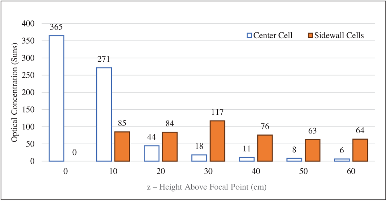
Figure 11: Optical concentration received by center and sidewall cells at different heights from the focal point under 1000 W/m2 DNI
Fig. 12 illustrates the variation of power received by the center and sidewall cells at different vertical positions from the focal point, under 1000 W/m2 DNI. At the focal point (0 cm), nearly all the power is received by the center cell, with a peak value of approximately 35 W. As the height increases, power at the center decreases sharply, while sidewall power rises initially, reaching a maximum around 30 cm. Beyond this point, both center and sidewall powers decline gradually. The fitted polynomial trendlines reflect the nonlinear nature of energy distribution along the vertical axis. The results indicate that concentrated energy shifts from the center toward the sidewalls with increasing distance, before dissipating further. These findings are consistent with the heat spreading trend observed in the calculated thermal data and help define the vertical range suitable for receiver or photovoltaic cell placement.
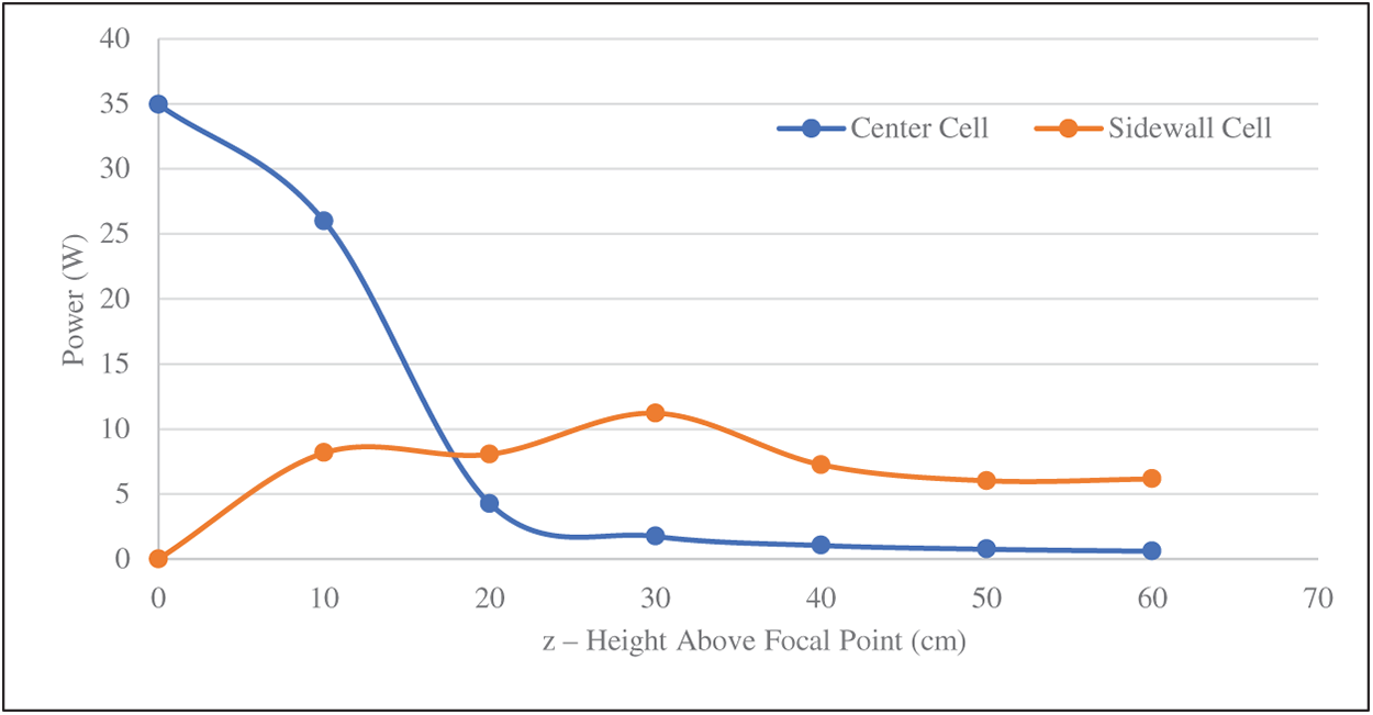
Figure 12: Variation of power received by the center and sidewall cells at different distances from the focal point under 1000 W/m2 DNI
This study presents a detailed multi-physics investigation of a novel Multi-Focal Pyramidal Array (MFPA)-based Concentrated Photovoltaic (CPV) system that addresses the long-standing challenge of simultaneously achieving high optical efficiency and thermal stability in cost-effective solar concentrators. The MFPA utilizes a geometrically optimized pyramidal Fresnel lens system to redistribute focused sunlight across staggered photovoltaic receivers, allowing for tiered energy extraction and reduced thermal hotspots. The main findings of the present study are the following:
• The MFPA concentrator achieved a 120× geometric concentration ratio with an RMS focal radius of 2.48 mm, directing over 92% of incident rays onto active cell surfaces.
• A wide ±15° acceptance angle enabled single-axis tracking with less than 5% performance loss.
• Thermal simulations showed a maximum focal point temperature of 161°C, while photovoltaic cell operating temperatures remained below 110°C without active cooling.
• Replacing multi-junction cells with monocrystalline silicon reduced material costs by ~80%. When combined with the simulated electrical power output, this configuration improved the power-per-cost ratio by 25% (1.8 W/$) compared to a referenced conventional HCPV system.
• Passive cooling reduced thermal management complexity by 40%, eliminating auxiliary systems under standard conditions.
• The MFPA design provides a scalable, cost-effective, and thermally robust CPV solution, offering a sustainable pathway for high-concentration solar energy deployment.
• Future work will address hybrid cooling strategies and structural robustness under outdoor conditions to validate long-term operational stability.
Acknowledgement: We would like to acknowledge the Imam Abdulrahman Bin Faisal University for the assistance and support provided to conduct very efficient research.
Funding Statement: The authors received no specific funding for this study.
Author Contributions: conceptualization, Mussad Mohammed Al-Zahrani, Taher Maatallah; methodology, Mussad Mohammed Al-Zahrani, Taher Maatallah; software, Mussad Mohammed Al-Zahrani, Taher Maatallah; methodology, Mussad Mohammed Al-Zahrani, Taher Maatallah; formal analysis, Mussad Mohammed Al-Zahrani, Taher Maatallah; investigation, Mussad Mohammed Al-Zahrani, Taher Maatallah; resources, Mussad Mohammed Al-Zahrani, Taher Maatallah; data curation, Mussad Mohammed Al-Zahrani, Taher Maatallah; writing—original draft preparation, Mussad Mohammed Al-Zahrani, Taher Maatallah; writing—review and editing, Mussad Mohammed Al-Zahrani, Taher Maatallah; visualization, Mussad Mohammed Al-Zahrani, Taher Maatallah; supervision, Mussad Mohammed Al-Zahrani, Taher Maatallah. All authors reviewed the results and approved the final version of the manuscript.
Availability of Data and Materials: The data supporting this study’s findings are available from the corresponding author upon reasonable request.
Ethics Approval: Not applicable.
Conflicts of Interest: The authors declare no conflicts of interest to report regarding the present study.
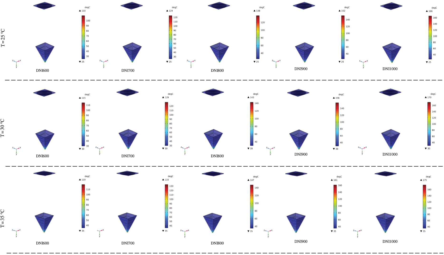
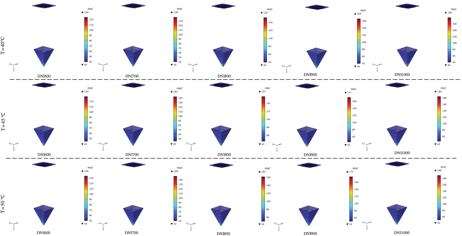
Figure A1: Simulated temperature distributions on a CPV cell placed within a pyramid-shaped solar concentrator under varying ambient conditions. Each row corresponds to a different outdoor temperature (T = 25°C to 50°C in 5°C increments), and each column shows the impact of increasing direct normal irradiance (DNI = 600 to 1000 W/m2)
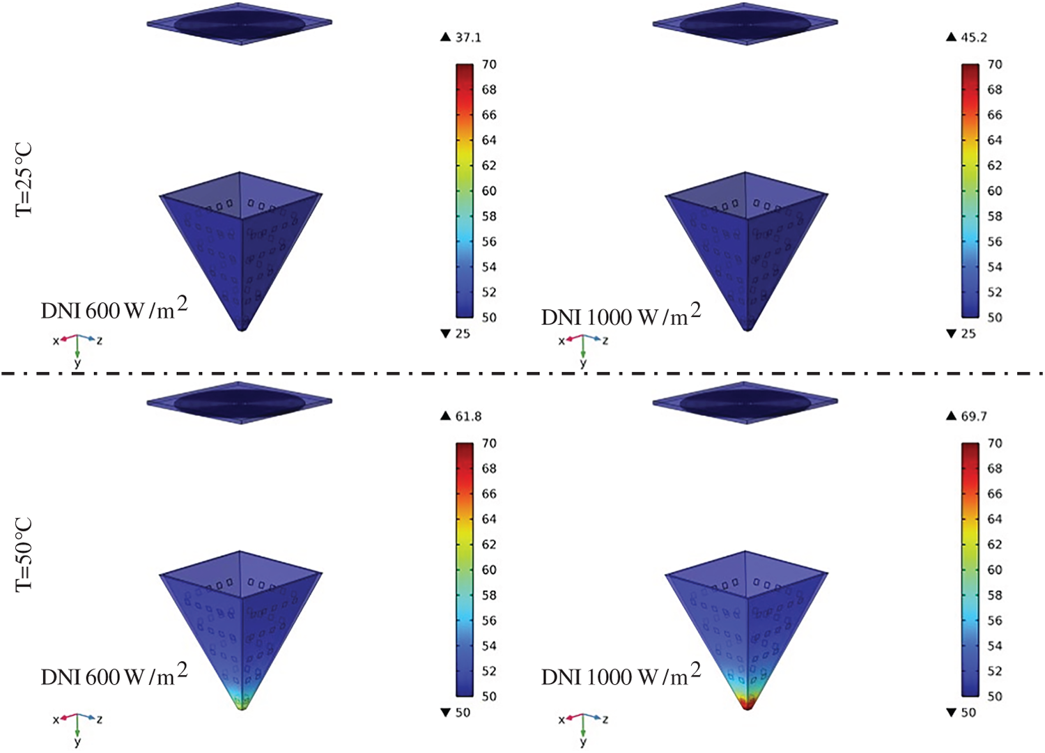
Figure A2: Simulated temperature distributions at a horizontal plane located 30 cm above the focal region of the pyramid-shaped solar concentrator under varying ambient conditions. Each row represents a different ambient temperature (T = 25°C and 50°C), while each column shows the effect of increasing direct normal irradiance (DNI = 600 to 1000 W/m2)
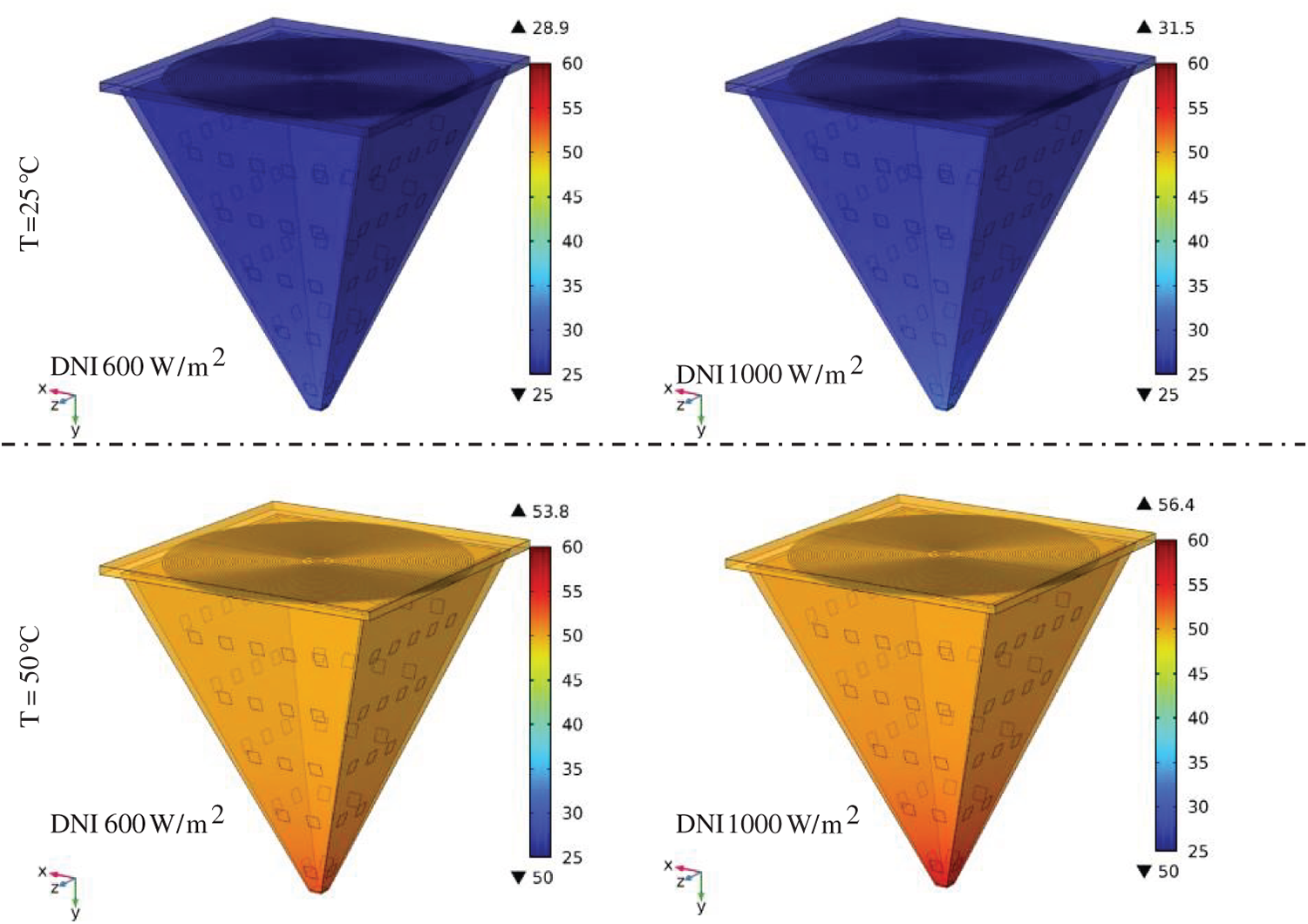
Figure A3: Simulated temperature distributions at a horizontal plane located 60 cm above the focal region of the pyramid-shaped solar concentrator under varying ambient conditions. Each row represents a different ambient temperature (T = 25°C and 50°C), while each column shows the effect of increasing direct normal irradiance (DNI = 600 and 1000 W/m2)
References
1. Awasthi A, Shukla AK, Murali Manohar SR, Dondariya C, Shukla KN, Porwal D, et al. Review on sun tracking technology in solar PV system. Energy Rep. 2020;6:392–405. doi:10.1016/j.egyr.2020.02.004. [Google Scholar] [CrossRef]
2. Forcade G. High-efficiency III-V semiconductor device and system optimization for photovoltaic applications [dissertation]. Ottawa, ON, Canada: University of Ottawa; 2025. [Google Scholar]
3. Qandil H, Wang S, Zhao W. Algorithmically optimized hemispherical dome as a secondary optical element for the Fresnel lens solar concentrator. Appl Sci. 2019;9(13):2757. doi:10.3390/app9132757. [Google Scholar] [CrossRef]
4. Agrawal M, Chhajed P, Chowdhury A. Performance analysis of photovoltaic module with reflector: optimizing orientation with different tilt scenarios. Renew Energy. 2022;186:10–25. doi:10.1016/j.renene.2021.12.149. [Google Scholar] [CrossRef]
5. Abbas S, Yuan Y, Hassan A, Zhou J, Ahmed A, Yang L, et al. Effect of the concentration ratio on the thermal performance of a conical cavity tube receiver for a solar parabolic dish concentrator system. Appl Therm Eng. 2023;227:120403. doi:10.1016/j.applthermaleng.2023.120403. [Google Scholar] [CrossRef]
6. Kolamroudi MK, Ilkan M, Egelioglu F, Safaei B. A comparative study of LCPV by mirror reflection against other systems: recent techniques, implications, and performances. Sol Energy. 2023;250:70–90. doi:10.1016/j.solener.2022.12.017. [Google Scholar] [CrossRef]
7. Kolamroudi MK, Ilkan M, Egelioglu F, Safaei B. Maximization of the output power of low concentrating photovoltaic systems by the application of reflecting mirrors. Renew Energy. 2022;189:822–35. doi:10.1016/j.renene.2022.03.031. [Google Scholar] [CrossRef]
8. Bukit FRA, Sani A, Hasugian IA, Butar-Butar TDP. The affect of solar panel tilt angle with reflector on the output power using calculation and experimental methods. In: Proceedings of the 2022 6th International Conference on Electrical, Telecommunication and Computer Engineering (ELTICOM); 2022 Nov 22–23; Medan, Indonesia. p. 80–4. doi:10.1109/ELTICOM57747.2022.10037921. [Google Scholar] [CrossRef]
9. Maatallah T, Alzahrani M, Almatar A, Wahab F, Ali S. Numerical investigation of natural light transmission through fiber optics. Energies. 2025;18(5):1103. doi:10.3390/en18051103. [Google Scholar] [CrossRef]
10. Rashid FL, Al-Obaidi MA, Mahdi AJ, Ameen A. Advancements in Fresnel lens technology across diverse solar energy applications: a comprehensive review. Energies. 2024;17(3):569. doi:10.3390/en17030569. [Google Scholar] [CrossRef]
11. Jost N, Jacobo-Martín A, Vallerotto G, Hernández JJ, Garcia-Sanchez A, Domínguez C, et al. Fabrication of high-performance lens arrays for micro-concentrator photovoltaics using ultraviolet imprinting. Int J Adv Manuf Technol. 2024;131(12):5961–70. doi:10.1007/s00170-024-13350-z. [Google Scholar] [CrossRef]
12. Yi SS, Woon LLY, Siang AJLM, Kah HL, Mousay KAH, Mustafa F, et al. Efficiency performance optimization of photovoltaic systems with solar concentrators. J Adv Res Appl Sci Eng Tech. 2024:134–44. doi:10.37934/araset.57.1.134144. [Google Scholar] [CrossRef]
13. Miller DC, Kurtz SR. Durability of Fresnel lenses: a review specific to the concentrating photovoltaic application. Sol Energy Mater Sol Cells. 2011;95(8):2037–68. doi:10.1016/j.solmat.2011.01.031. [Google Scholar] [CrossRef]
14. Nawawi MAH, Baharom MNR. A study of implementation Fresnel lens with tracking positioning ability to achieve optimum concentrated heat on the solar heater element. Prog Eng Appl Technol. 2024;5(2):225–34. [Google Scholar]
15. Kopalakrishnaswami AS, Natarajan SK. Thermal analysis of modified conical cavity receiver for a paraboloidal dish collector system. Energy Sources Part A Recovery Util Environ Eff. 2021;47(2):1–12. doi:10.1080/15567036.2021.2017516. [Google Scholar] [CrossRef]
16. Wang H. Comparative study of a fixed-focus Fresnel lens solar concentrator/conical cavity receiver system with and without glass cover installed in a solar cooker. Sustainability. 2023;15(12):9450. doi:10.3390/su15129450. [Google Scholar] [CrossRef]
17. Younes K, Apostoleris H, Bin Saad M, Al Ghaferi A, Chiesa M. Realizing high photovoltaic power densities with tracking-integrated concentrator photovoltaics. Front Energy Res. 2022;10:842201. doi:10.3389/fenrg.2022.842201. [Google Scholar] [CrossRef]
18. Bunthof LAA, Bos-Coenraad J, Corbeek WHM, Vlieg E, Schermer JJ. The illumination angle dependency of CPV solar cell electrical performance. Sol Energy. 2017;144:166–74. doi:10.1016/j.solener.2017.01.026. [Google Scholar] [CrossRef]
19. Hutauruk S, Sianturi L, Togatorop I. Fresnel lenses and auto tracking to increase solar panel output power. Indones J Electr Eng Comput Sci. 2024;34(2):1389. doi:10.11591/ijeecs.v34.i2.pp1389-1398. [Google Scholar] [CrossRef]
20. Yun MJ, Sim YH, Lee DY, Cha SI. Automated shape-transformable self-solar-tracking tessellated crystalline Si solar cells using in situ shape-memory-alloy actuation. Sci Rep. 2022;12(1):1597. doi:10.1038/s41598-022-05466-7. [Google Scholar] [PubMed] [CrossRef]
21. Price JS, Grede AJ, Wang B, Lipski MV, Fisher B, Lee KT, et al. High-concentration planar microtracking photovoltaic system exceeding 30% efficiency. Nat Energy. 2017;2(8):17113. doi:10.1038/nenergy.2017.113. [Google Scholar] [CrossRef]
22. Sheikh YA, Butt AD, Paracha KN, Awan AB, Bhatti AR, Zubair M. An improved cooling system design to enhance energy efficiency of floating photovoltaic systems. J Renew Sustain Energy. 2020;12(5):053502. doi:10.1063/5.0014181. [Google Scholar] [CrossRef]
23. Wang WW, Liu T, Guo JZ, Li B, Zhang HL, Cai Y, et al. Experimental investigation on the thermal performance of high-concentrated photovoltaic module utilizing the thermal sink of a novel Fan-shaped plate pulsating heat pipe. Appl Energy. 2025;377:124365. doi:10.1016/j.apenergy.2024.124365. [Google Scholar] [CrossRef]
24. Jatau T, Bello-Ochende T, Malan A. Novel design of centralized square array of pin-fins in microchannels heat sink for thermal management of high concentrator photovoltaic systems. Appl Therm Eng. 2025;260:124943. doi:10.1016/j.applthermaleng.2024.124943. [Google Scholar] [CrossRef]
25. Abd-Elhady MM, Elhendawy MA, Abd-Elmajeed MS, Rizk RB. Enhancing photovoltaic systems: a comprehensive review of cooling, concentration, spectral splitting, and tracking techniques. Next Energy. 2025;6:100185. doi:10.1016/j.nxener.2024.100185. [Google Scholar] [CrossRef]
26. Kumar S, Kumar R, Thakur R, Kumar S, Lee D. Effects of climate variables and nanofluid-based cooling on the efficiency of a liquid spectrum filter-based concentrated photovoltaic thermal system. J Therm Anal Calorim. 2024;149(5):2273–91. doi:10.1007/s10973-023-12836-4. [Google Scholar] [CrossRef]
27. Soliman AMA, Hassan H, Ookawara S. An experimental study of the performance of the solar cell with heat sink cooling system. Energy Proc. 2019;162:127–35. doi:10.1016/j.egypro.2019.04.014. [Google Scholar] [CrossRef]
28. Obaid AH, Mahdi EJ, Muslem AH, Jafer AN, Abed SS, Khuder TY. Evaluation of the performance of silicon solar cell with Fresnel lens as photovoltaic solar concentrator. Iraqi J Sci. 2021;62(9):3400–6. doi:10.24996/ijs.2021.62.9(si).11. [Google Scholar] [CrossRef]
29. Valera A, Fernández EF, Rodrigo PM, Almonacid F. Feasibility of flat-plate heat-sinks using microscale solar cells up to 10,000 suns concentrations. Sol Energy. 2019;181:361–71. doi:10.1016/j.solener.2019.02.013. [Google Scholar] [CrossRef]
30. AlFalah G, Maatallah TS, Alzahrani M, Al-Amri FG. Optimization and feasibility analysis of a microscale pin-fins heat sink of an ultrahigh concentrating photovoltaic system. Int J Energy Res. 2020;44(14):11852–71. doi:10.1002/er.5826. [Google Scholar] [CrossRef]
31. Ibrahim KA, Luk P, Luo Z. Cooling of concentrated photovoltaic cells—a review and the perspective of pulsating flow cooling. Energies. 2023;16(6):2842. doi:10.3390/en16062842. [Google Scholar] [CrossRef]
32. Maatallah T, Houcine A, Saeed F, Khan S, Ali S. Simulated performance analysis of a hybrid water-cooled photovoltaic/parabolic dish concentrator coupled with conical cavity receiver. Sustainability. 2024;16(2):544. doi:10.3390/su16020544. [Google Scholar] [CrossRef]
33. Felsberger R, Buchroithner A, Gerl B, Wegleiter H. Conversion and testing of a solar thermal parabolic trough collector for CPV-T application. Energies. 2020;13(22):6142. doi:10.3390/en13226142. [Google Scholar] [CrossRef]
34. Shanks K, Senthilarasu S, Mallick TK. Optics for concentrating photovoltaics: trends, limits and opportunities for materials and design. Renew Sustain Energy Rev. 2016;60:394–407. doi:10.1016/j.rser.2016.01.089. [Google Scholar] [CrossRef]
35. Aziznezhad AH, Gorjian S, Mokhtarzadeh H. Design, development and experimental evaluation of a concentrator agrivoltaic system with integrated spectrally splitting Fresnel lens. Results Eng. 2024;24:103119. doi:10.1016/j.rineng.2024.103119. [Google Scholar] [CrossRef]
36. Tian P, Han Y, Li W, Yang X, Wang M, Yu J. New design scheme for and application of Fresnel lens for broadband photonics terahertz communication. Sensors. 2024;24(23):7592. doi:10.3390/s24237592. [Google Scholar] [PubMed] [CrossRef]
37. Born M, Wolf E, Bhatia AB. Principles of optics: electromagnetic theory of propagation, interference and diffraction of light. 7th ed. Cambridge, UK: Cambridge University Press; 1999. [Google Scholar]
38. Sekiguchi T, Wolf KB. The Hamiltonian formulation of optics. Am J Phys. 1987;55(9):830–5. doi:10.1119/1.14999. [Google Scholar] [CrossRef]
39. Grattan-Guinness I. Joseph Fourier, théorie analytique de la chaleur, 1822. In: Landmark writings in western mathematics 1640–1940. Amsterdam, The Netherlands: Elsevier; 2005. p. 354–65. doi:10.1016/b978-044450871-3/50107-8. [Google Scholar] [CrossRef]
40. Ahmed A, Alzahrani M, Shanks K, Sundaram S, Mallick TK. Reliability and temperature limits of the focal spot of a primary optical component for an ultra-high concentrated photovoltaic system. AIP Conf Proc. 2022;2550(1):040001. doi:10.1063/5.0099091. [Google Scholar] [CrossRef]
Cite This Article
 Copyright © 2025 The Author(s). Published by Tech Science Press.
This work is licensed under a Creative Commons Attribution 4.0 International License , which permits unrestricted use, distribution, and reproduction in any medium, provided the original work is properly cited.
 Downloads
 Citation Tools