
 Submit a Paper
 Propose a Special lssue
 Open Access
ARTICLE
Improved Interleaved Single-Ended Primary Inductor-Converter for Single-Phase Grid-Connected System
Noorul Islam Centre for Higher Education, Nagarkovil, 629180, Tamilnadu, India
* Corresponding Author: T. J. Thomas Thangam. Email:
Intelligent Automation & Soft Computing 2023, 35(3), 3459-3478. https://doi.org/10.32604/iasc.2023.025521
Received 26 November 2021; Accepted 13 February 2022; Issue published 17 August 2022
 View Full Text
 Download PDF
Abstract
The generation of electricity based on renewable energy sources, particularly Photovoltaic (PV) system has been greatly increased and it is simply instigated for both domestic and commercial uses. The power generated from the PV system is erratic and hence there is a need for an efficient converter to perform the extraction of maximum power. An improved interleaved Single-ended Primary Inductor-Converter (SEPIC) converter is employed in proposed work to extricate most of power from renewable source. This proposed converter minimizes ripples, reduces electromagnetic interference due to filter elements and the continuous input current improves the power output of PV panel. A Crow Search Algorithm (CSA) based Proportional Integral (PI) controller is utilized for controlling the converter switches effectively by optimizing the parameters of PI controller. The optimized PI controller reduces ripples present in Direct Current (DC) voltage, maintains constant voltage at proposed converter output and reduces overshoots with minimum settling and rise time. This voltage is given to single phase grid via Voltage Source Inverter (VSI). The command pulses of VSI are produced by simple PI controller. The response of the proposed converter is thus improved with less input current. After implementing CSA based PI the efficiency of proposed converter obtained is and the Total Harmonic Distortion (THD) is found to be . The dynamics and closed loop operation is designed and modeled using MATLAB Simulink tool and its behavior is performed.Keywords
Abbreviations
| PV | Photovoltaic |
| CSA | Crow Search Algorithm |
| SEPIC | Single-ended Primary Inductor-Converter |
| PI | Proportional Integral |
| DC | Direct Current |
| VSI | Voltage Source Inverter |
| THD | Total Harmonic Distortion |
| MIC | Module-integrated converters |
| L-C | inductor-capacitor |
| VSS-LMS | Variable Step Size-Least Mean Square |
| PCC | Point of Common Coupling |
| SPV | Solar PV |
| UPF | Unified Power Flow |
| CSI | Current Source Inverter |
| GSA | Gravitational Search Algorithm |
| FLC | Fuzzy Logic Control |
| MPPT | Maximum power point tracking |
| GWO | Grey Wolf Optimization |
| GD | Gradient Descent |
| PSO | Particle Swarm Optimization |
| AC | Alternating Current |
| SC | Short Circuit |
| OC | Open Circuit |
| PLL | Phase Locked Loop |
| PD | Phase Detector |
| LP | Loop filter |
| VCO | Voltage Controlled Oscillator |
| LPF | Low Pass Filter |
| CCM | Continuous Conduction Mode |
SYMBOLS
| | Reference voltage |
| | Actual voltage |
| | Photocurrent |
| | Open circuit voltage |
| | Series resistance |
| | Short circuit current |
| | Shunt resistance |
| | Voltage per temperature coefficient |
| | Temperature |
| | Electron charge |
| | Current per temperature coefficient |
| | Input and output voltage |
| | Peak to peak ripples in inductor currents |
| | Input and output currents |
| | Input inductors of the converter |
| | Output inductors of the converter |
| | Middle capacitors of the converter |
| | Peak to peak ripple of coupling capacitor voltage |
| | Output capacitor |
| | Proportional gain & Integral gain |
| | Amplitude |
| | Angle |
| | Frequency |
| | Phase angle of input signal |
| | Damping ratio |
The world’s rising demand for electricity has improved the productivity and widespread use of renewable energy. Among most significant renewable energy sources utilized for power generation, solar PV array has attracted most of the researchers [1]. The PV system typically consists of PV panels that are linked in a combination of series-parallel to meet centralized power inverter’s high input voltage specifications for grid connections. The PV array based Sub module-integrated converters (subMICs) have the ability of increasing the production of PV energy by eliminating losses in power that arise owing to intra panel mismatch. The double-frequency ripple occurs because of
A
Design of sliding mode controller for photo voltaic MPPT is proposed. This is fed to SEPIC converter and it is applied to a broad variety of PV fed converters [14]. A PV system interfaced with SEPIC converter is proposed to reduce the oscillations occurring in the maximum power point. It provides positive load voltage with non-pulsating nature of load current [15]. Depending on the availability of solar energy, both synchronous SEPIC as well as Zeta converter via MPPT photo voltaic array overcome the problem of rise in power demand [16]. The synchronous Cuk converter based solar array is presented to minimize losses due to conduction and switching [17]. An improved DC-DC converter dependent on the integration of Cuk as well as single ended primary inductor converter is introduced for SPV applications. This converter utilizes only
A Fuzzy Logic Control (FLC) based SEPIC for MPPT is proposed. With reduced voltage stress, this SEPIC has high stepped potential design. The Zeta converter’s output current is continuous with lesser output ripple compared to SEPIC and Cuk converters [21]. Using Grey Wolf Optimization (GWO), a MPPT design for solar array is proposed to overcome the drawback of lesser tracking efficiency and steady-state oscillations [22]. A novel Cuk–SEPIC converter dependent PV with hybrid GSA and PSO using MPPT minimizes ripples present in input current that aid maximum utilization of PV system [23]. The algorithm of perturb and observe suffers from lack of tracking direction issue and likely fails during huge insulation transformation condition. Through enhancement in perturb and observe algorithm, efforts were made to resolve these problems [24]. The latest optimized algorithms are incapable to resolve whole optimization difficulties. The combined optimization technique which improves the power tracking performance due to its simple implementation is crow search optimization, a finest algorithm which is used in hybrid combinations [25].
An improved interleaved DC-DC SEPIC converter is employed in proposed work. This converter boosts up the PV panel DC voltage. Conventionally PI controller is utilized for controlling DC link voltage. The parameters of PI are tuned by CSA. By optimizing PI controller with CSA, the ripples are reduced and constant voltage is maintained at proposed converter output with reduced settling time. This voltage is fed to
The proposed system’s schematic block representation presented in Fig. 1. It is composed of PV panel and is coupled with an improved interleaved DC-DC SEPIC converter that consists of four inductances and capacitances, two switches and diodes. As this converter circuit is having four inductances and capacitances, it is known as fourth order filter. At the input side it consists of PV panel with a voltage of
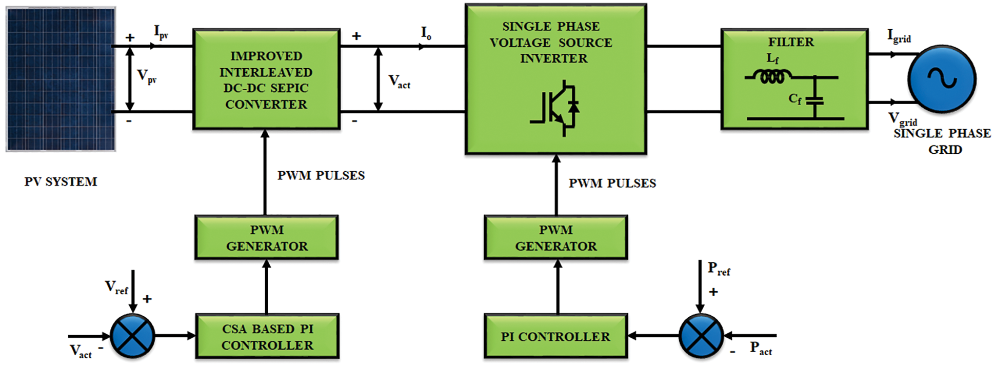
Figure 1: Proposed block diagram
The input voltage of
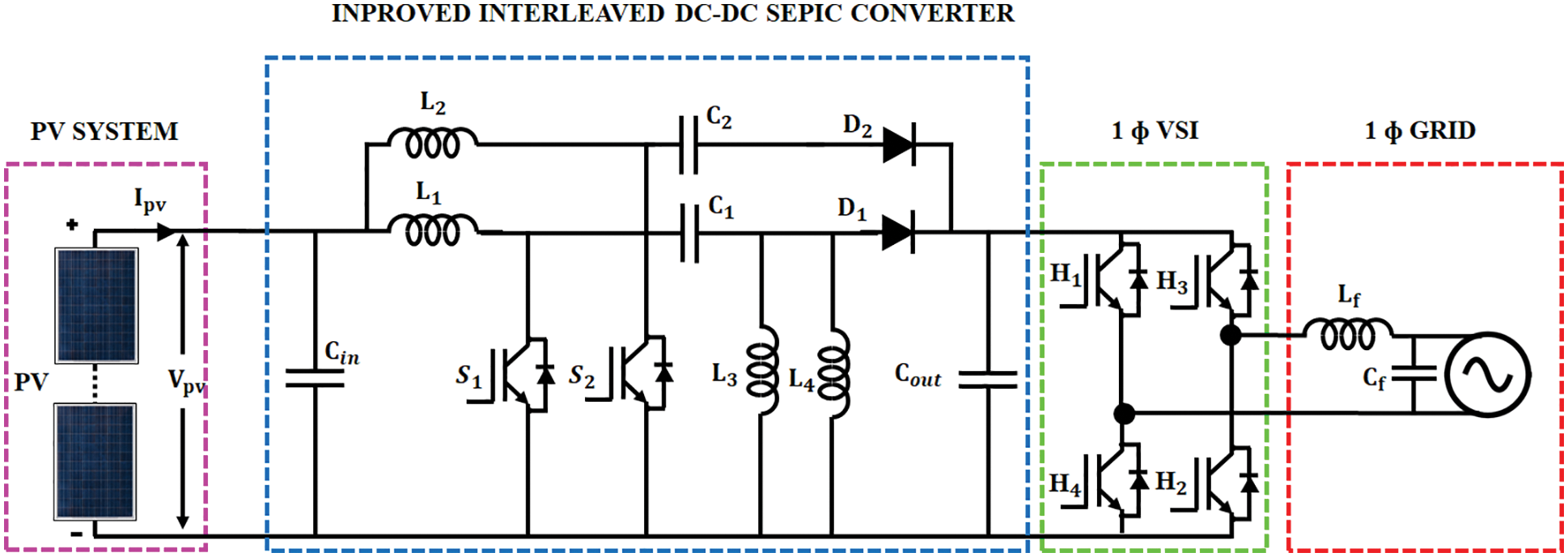
Figure 2: Schematic representation of PV fed improved interleaved DC-DC SEPIC converter
A solar cell is a tool used for conversion of photon energy into pollution-free electricity. The modules connected into series and parallel arrangements are responsible for producing clean and green electricity in order to create PV arrays. As a part of an electrical circuit, a single solar cell is depicted. It involves a p–n junction known as diode, a photocurrent generator illustrating the generation of light current and two resistors. One is arranged in series combination and another one in parallel defining the losses of Joule effect and recombination. This combination is then referred as a single model of PV cell diodes. The equivalent circuit of
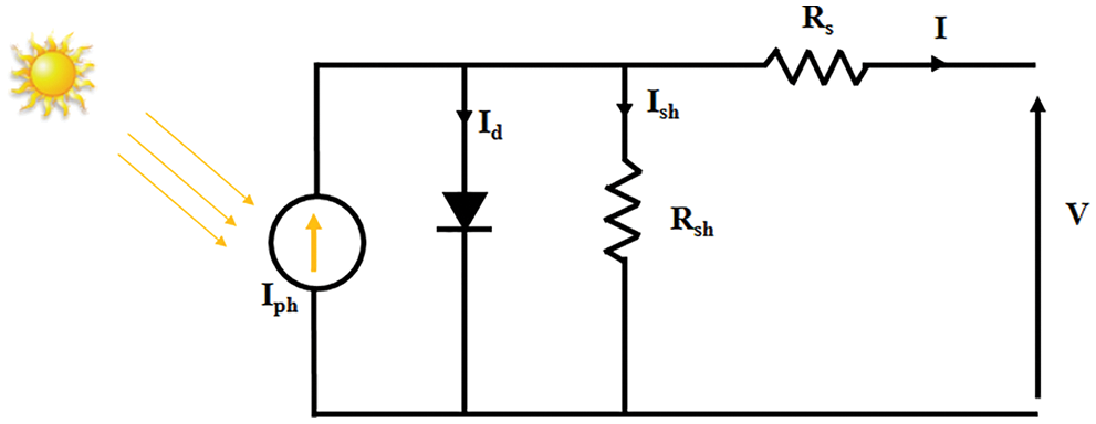
Figure 3: Equivalent circuit of PV panel
The model of PV panel is expressed mathematically as,
Thus the physical performance of solar panel depends on resistance connected in shunt and series fashion, solar irradiation and temperature.
3.2 Improved Interleaved DC-DC SEPIC Converter
In solar PV application, converters that are commonly used have faced serious issues on high input current ripples. This issue is overcome by instigating improved interleaved SEPIC converter. An interleaved DC-DC SEPIC converter contains multi-converter phase shifting control signal that works at equal switching frequencies. As a DC–DC converter, it produces extra power, minimizes harmonic distortion, and reduces electromagnetic interference and the schematic representation is mentioned in Fig. 4.
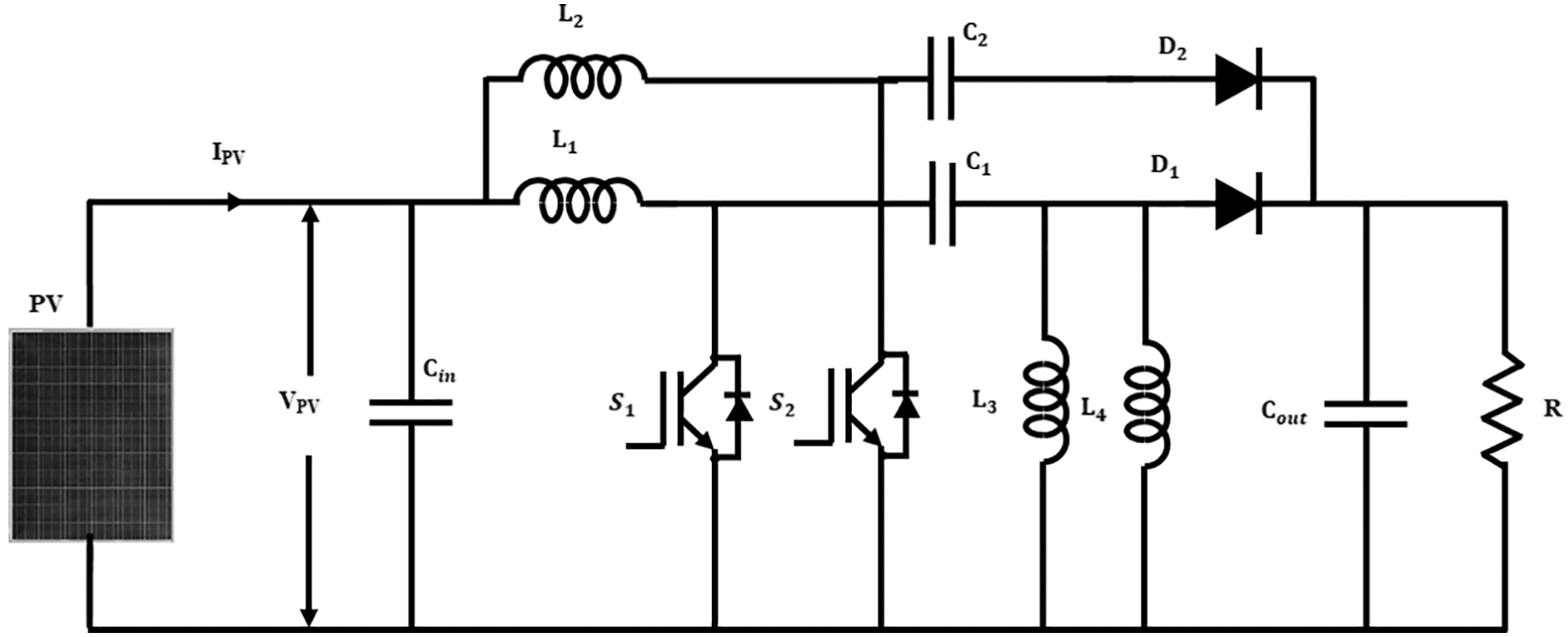
Figure 4: Circuit diagram of improved interleaved DC-DC SEPIC converter
The proposed converter delivers an outstanding conversion of buck-boost with non-inverted output potential which is compared to other interleaving DC–DC converters and achieves greater energy efficiency with minimum elements. The output voltage
Thus the interleaved SEPIC converter performs efficient boosting of input DC voltage with the generation of reduced electromagnetic interference and ripples.
3.3 CSA Based PI Controller for Proposed Converter
The PI controller parameters
Crows are regarded as clever birds having brilliant brain. The unfavorable condition is simply predicted by crows as they are having great capacity of face recognition. It will search for its food in an optimal manner by interacting with their families.
For instigating CSA, the parameters are regarded as follows.
No. of crows allocated as flock size is denoted as
Consider, crow
Condition 1: Crow
where,
Condition 2: Crow j realizes that it is being watched by crow i . For protecting its cache from pilfered, it starts moving to another location in the search space so as to fool crow
where,
3.3.1 Crow Search Algorithm Implementation for Optimization
The steps included in the implementation of crow search algorithm are,
Step 1: First initialize the problem and adjust the tuning parameters. The values for optimization problem, variables of decision and constraints are required to be defined. The parameters adjusted in CSA are flock size
Step 2: Initialize the location and memory of crows. In d-dimensional search place N crows are placed randomly as members of flock. Every crow denotes a possible solution of issue and d denotes the number of decision variables.
Step 3: Calculate fitness function for DC link voltage.
Step 4: Update memory using the expression
If the value of fitness function for DC link voltage of new crow location is greater than the value of memorized location, the crow updates its memory with the new location.
Step 5: Crows create novel location in search place as crow
Step 6: It tests the feasibility of novel location of every crow. If novel location of crow is viable, crow will update its location, otherwise crow will remain in its current location.
Step 7: Again calculate fitness function for DC link voltage.
Step 8: Until the iteration attains the value of maximum iteration, repeat the steps from 4–7. The finest position of memory in terms of DC link voltage as objective function is determined by controller’s optimal gain values.
The obtained values from the CSA optimization indicates efficient tuning of PI controller parameters. This maintains a constant DC link voltage with minimized ripples and settling time. The flowchart representing this process is evidently provided in Fig. 5.
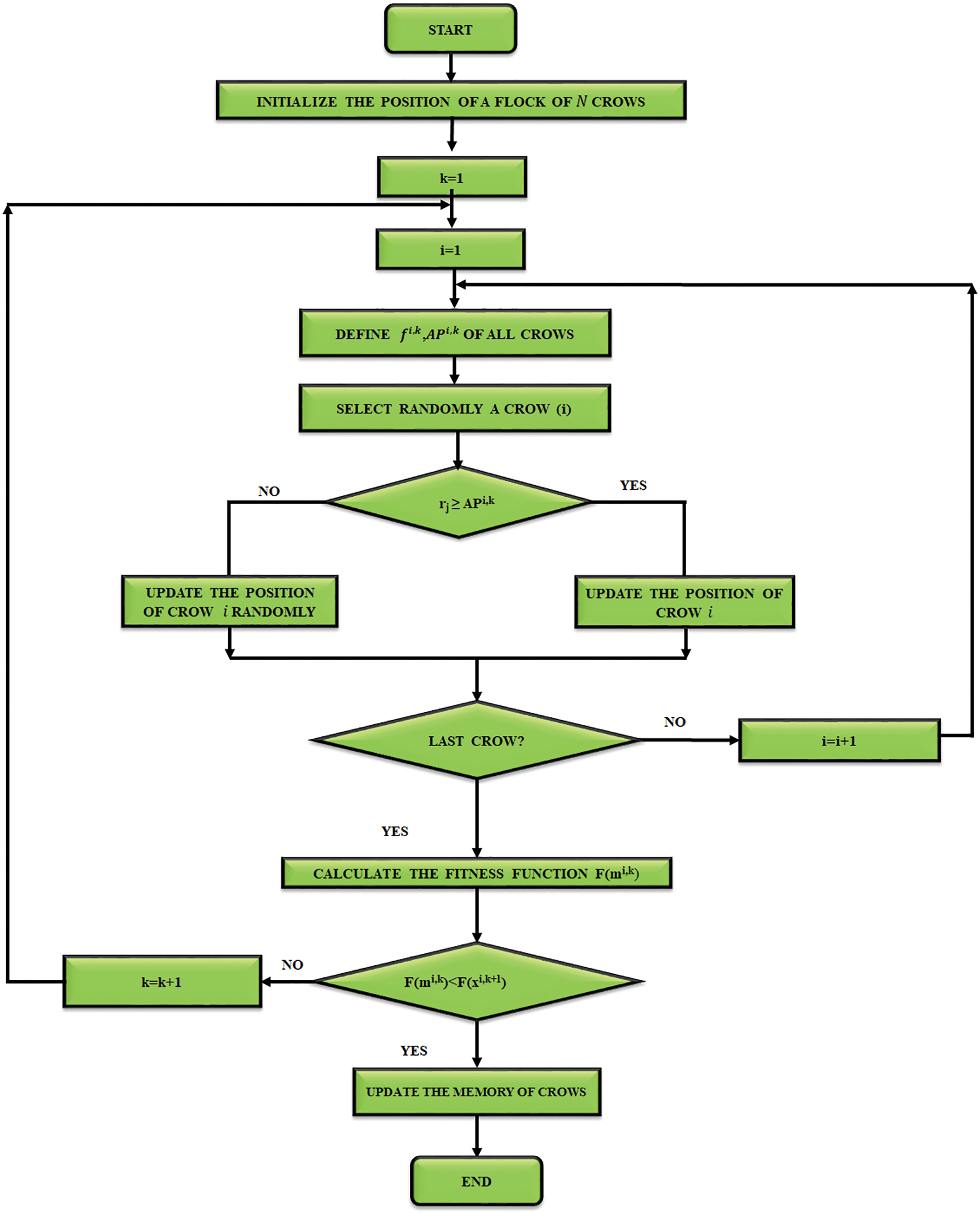
Figure 5: Flow chart of crow search algorithm
3.4 Grid Synchronization in Single Phase PV System
Fig. 6 shows the control structure of
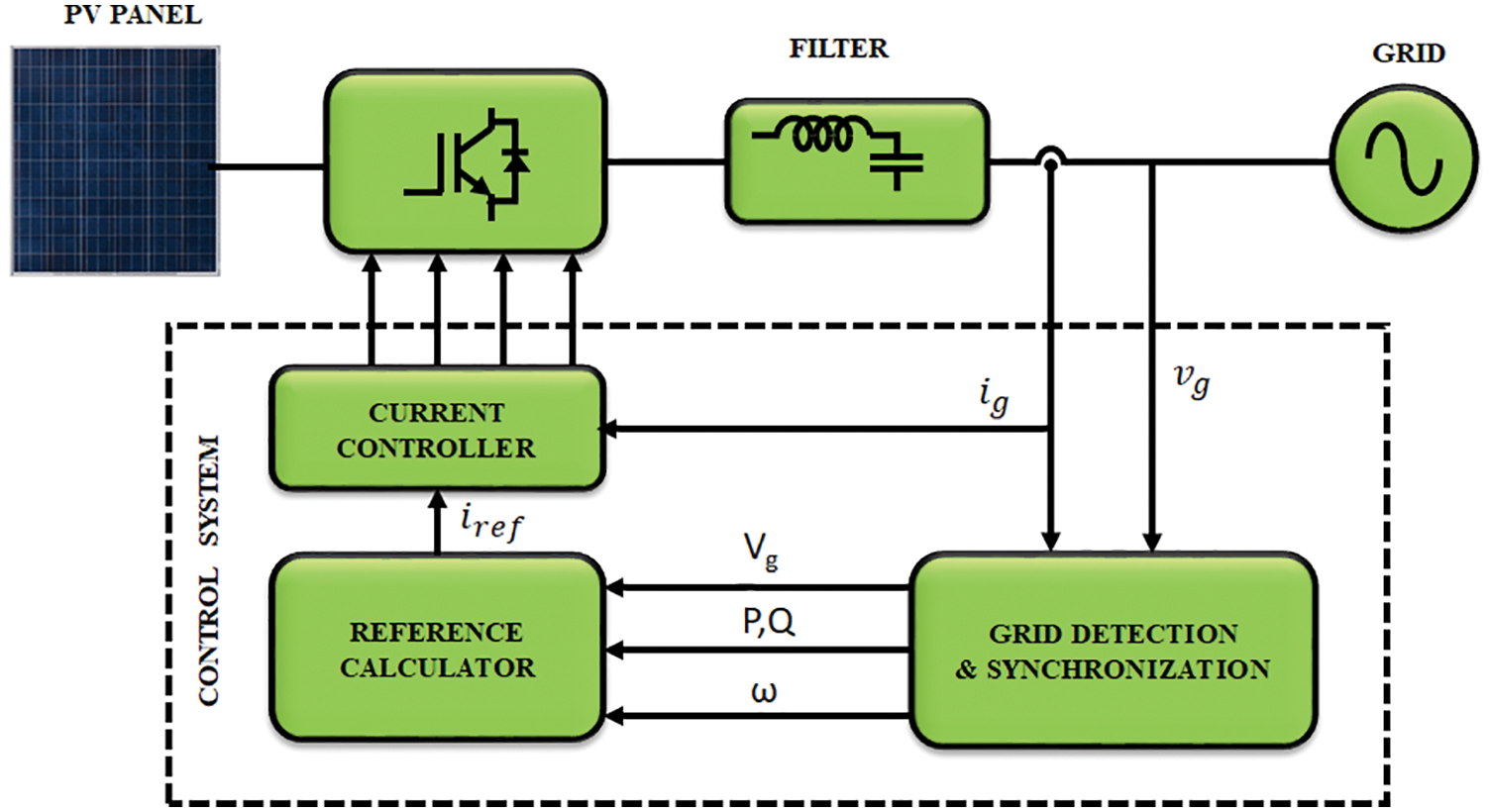
Figure 6: Control structure of
Normally, synchronization methods are classified in to two types as mathematical analysis method and PLL method. Among these methods, adaptive filtering based phase locked loop method gains more attraction. A fundamental PLL is represented in Fig. 7.
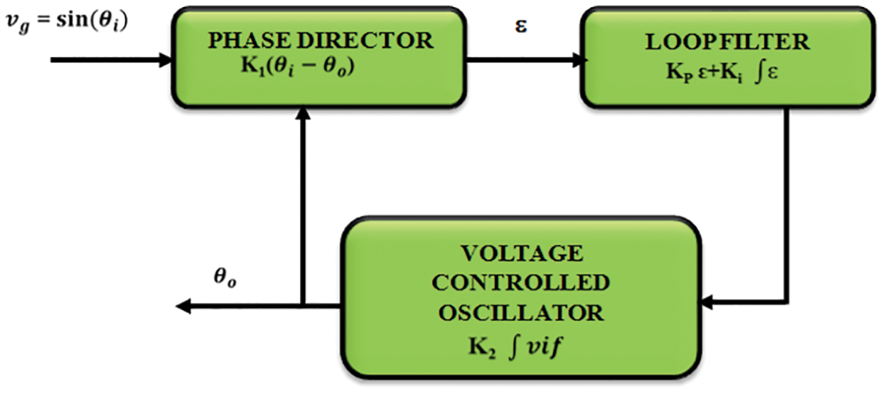
Figure 7: Basic PLL
The structure of PLL contains PD, LP and VCO. If first order LPF is utilized, a small signal model of
where,
where,
From Eq. (12), damping ratio and undamped natural frequency are given by,
when
The use of adaptive filter is another option for phase detection that perform self-adjusting of output using an error feedback loop.
3.4.1
Considering an ideal sinusoidal signal,
where,
Using PI controller
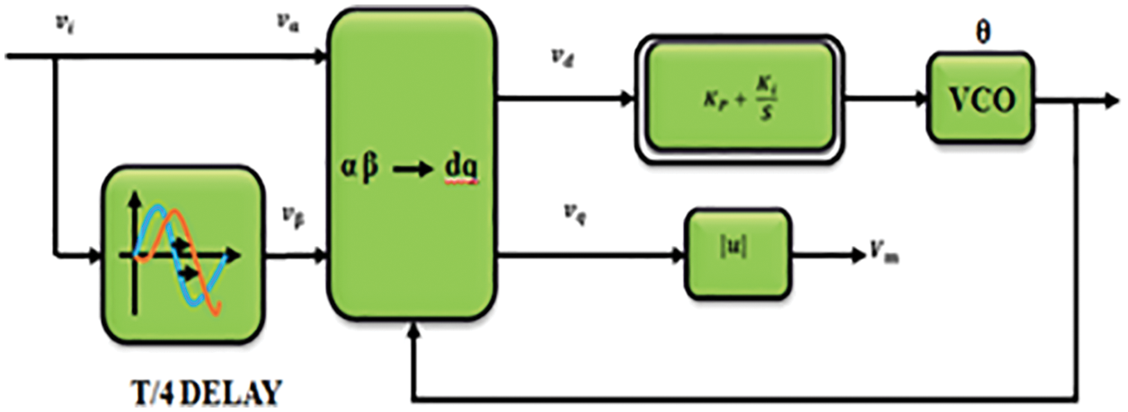
Figure 8: Structure of
The
The solar array output voltage is fed to an improved interleaved DC-DC SEPIC converter. Due to temperature variation, PV panel output link voltage does not maintain constant value and causes the occurrence of ripples. The CSA based proportional integral controller for proposed converter optimizes PI controller parameters that maintains constant voltage at proposed converter, reduces ripples and settling time. This voltage is given to
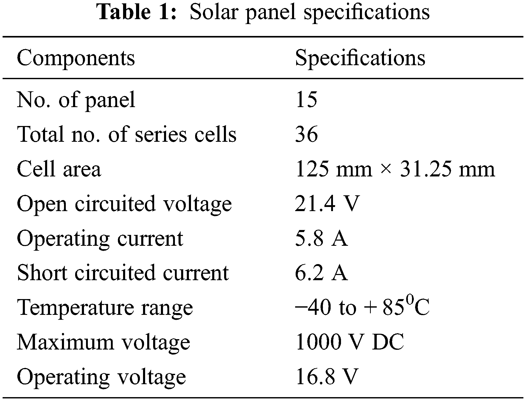
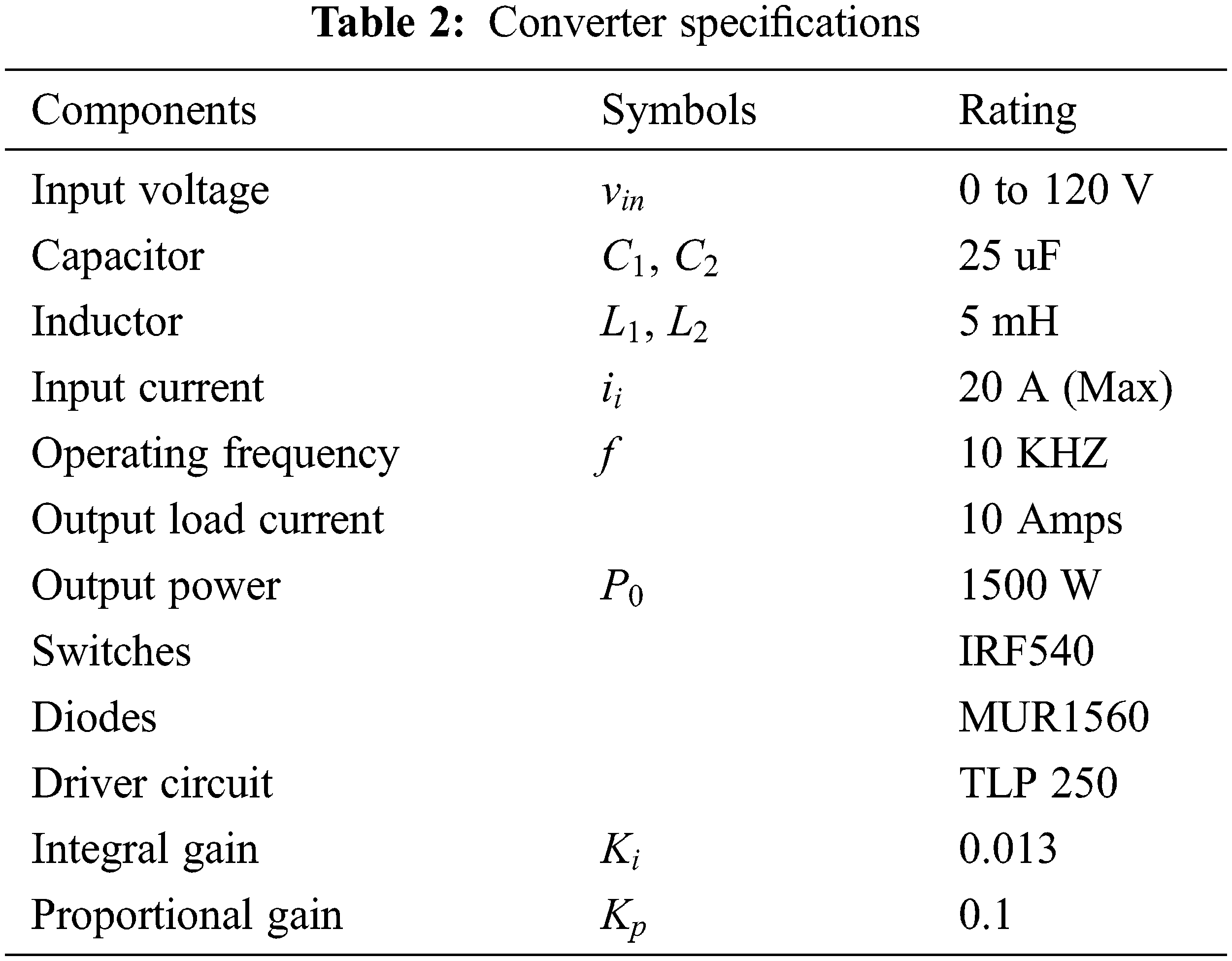
The solar panel specifications are represented in Tab. 1. The power rating of
The simulation results for photo voltaic integrated grid scheme is accomplished in time scale using Simulink that measures performance of converter for a given system. The complete model is obtained from sim-power system tool box. The PV panel voltage and input current waveform is indicated in Figs. 9a and 9b in which the voltage waveform of PV panel observes that voltage changes from
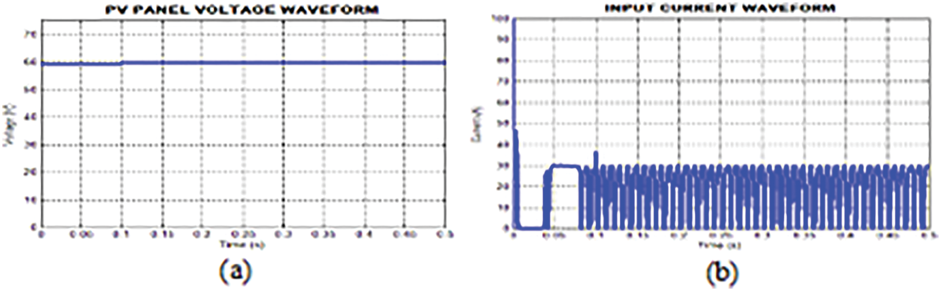
Figure 9: (a) PV panel voltage waveform (b) Input current waveform
The output DC voltage waveform using PI controller is represented in Fig. 10a. The output reveals that the voltage does not maintain constancy and so oscillations occur in this waveform. The converter output voltage waveform using CS-PI controller is given in Fig. 10b. It is noted that after
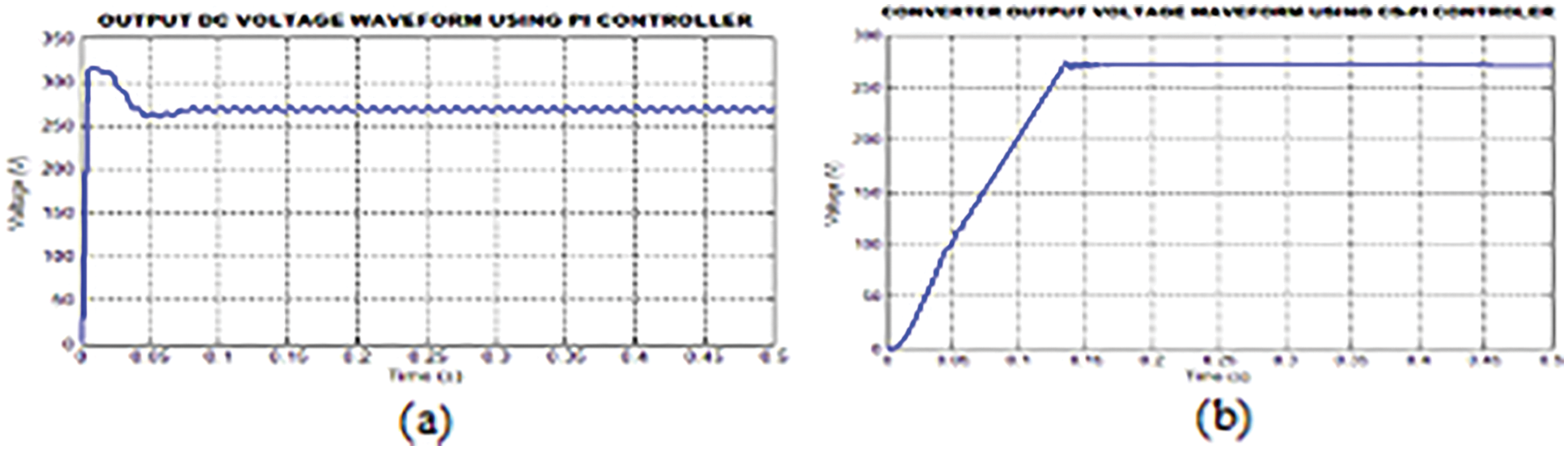
Figure 10: (a) Output waveform of DC voltage adopting PI controller (b) Output voltage waveform of converter adopting CS-PI controller
The output waveform of converter is depicted in Fig. 11. This waveform shows the output current from converter.
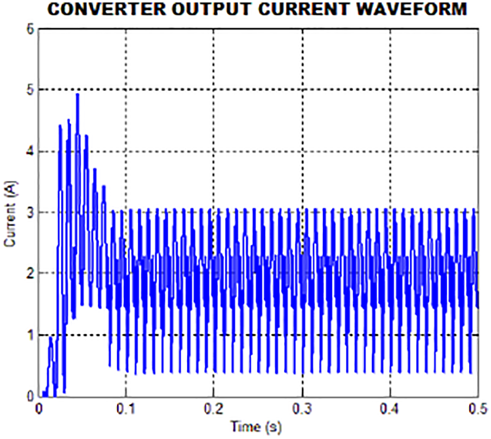
Figure 11: Converter output current waveform
The PWM pulses to the converter switches
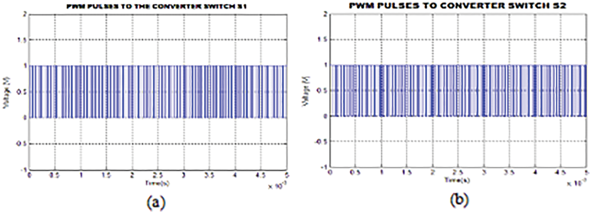
Figure 12: (a) & (b) PWM pulses to the converter switches
The waveforms for grid voltage and current are shown in Figs. 13a and 13b. Here, the grid voltage and current are maintained sinusoidal. The harmonics present in inverter current is similar & opposite of load current. The sinusoidal nature of grid current waveform is retained at fundamental frequency with non-linear load.
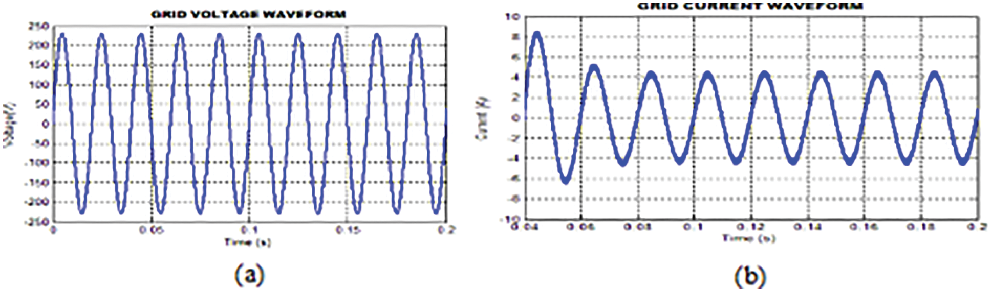
Figure 13: (a) & (b) Grid voltage and current waveform
The real and reactive power waveform is shown in Figs. 14a and 14b. It is noted that the real power decreases and then it attains at maximum power of
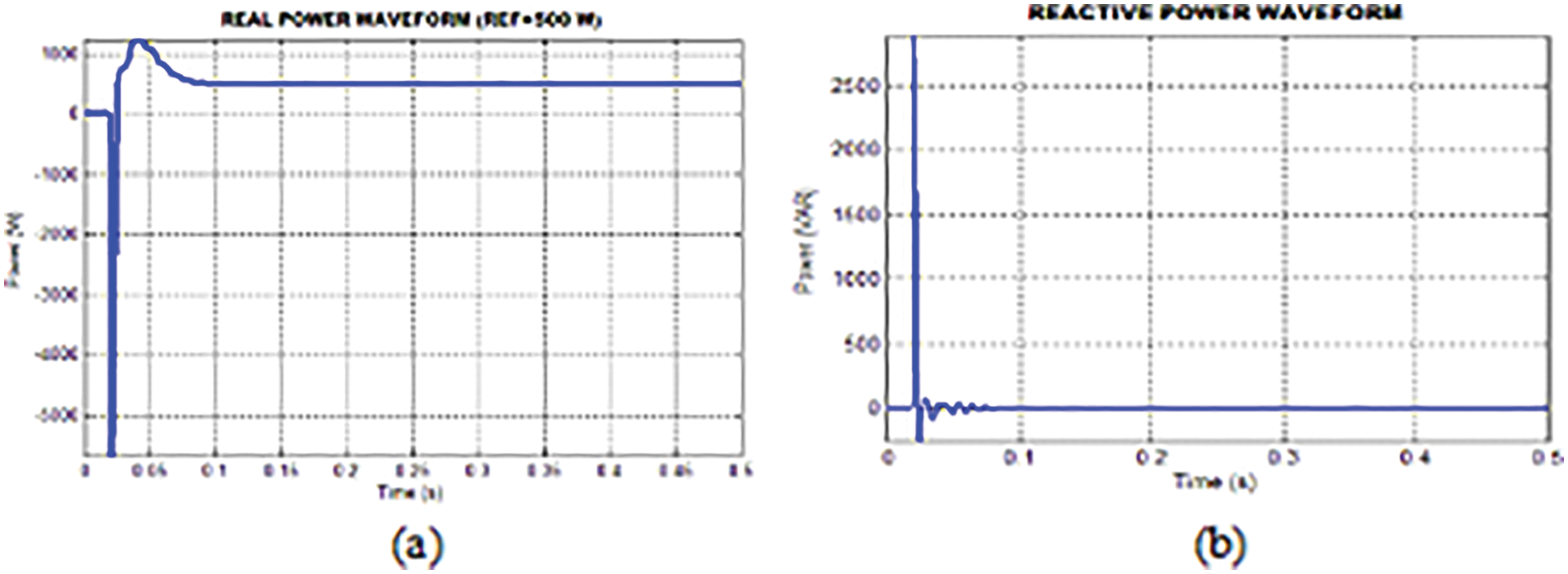
Figure 14: (a) & (b) Real and reactive power waveform
The grid current THD with PI and CS-PI is denoted in Figs. 15a and 15b. The behavior of PI and CS-PI controller is measured by evaluating the grid current THD using power analyzer. The grid current THD for conventional PI controller is
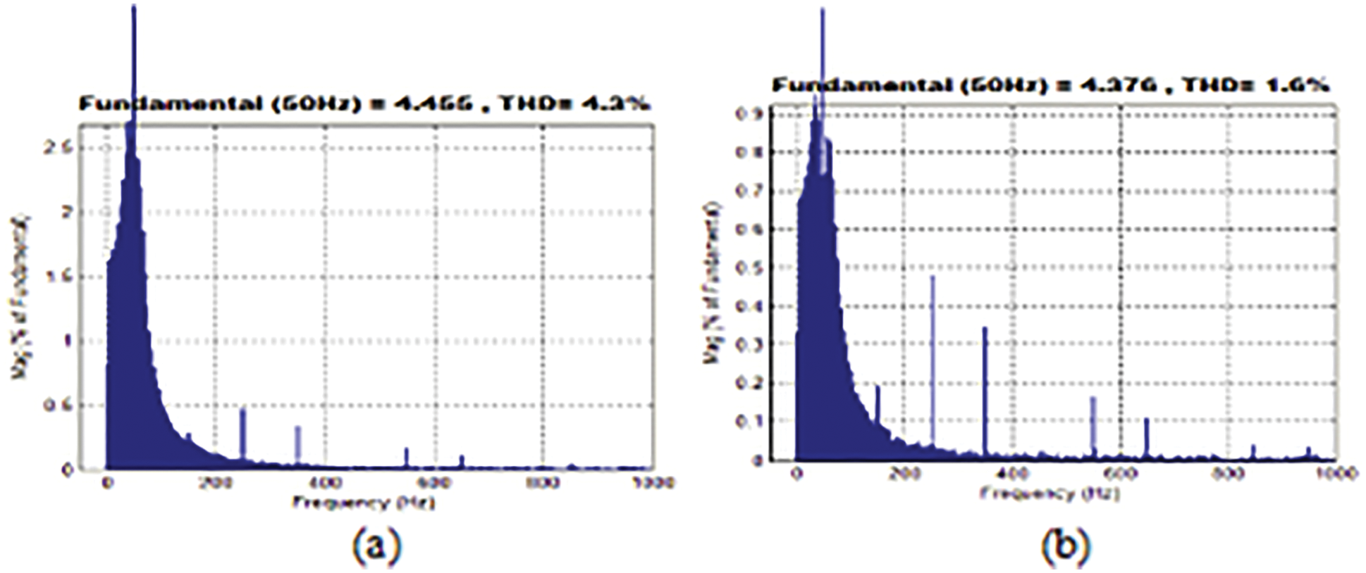
Figure 15: (a) & (b) Grid current THD with PI and CS-PI controller
4.2 Results for Hardware Implementation
The DSPIC30F2010 is cost effective since 8 bit microcontroller is used to develop proposed converter system prototype. The DC link voltage is used by the controller which is linked with DC-DC converter as feedback signal. This maintains converter output as steady state. The potential divider as well as Hall Effect sensor are used to measure real power at grid. The signals are performed by signal conditioners and then fed to microcontroller’s input point. Using inbuilt Analog to Digital Converter (ADC) unit, the signals are digitized.
The input DC voltage and current waveforms are given in Fig. 16. The PV panel output voltage & current waveform is shown which reveals that the variations occurring in voltage and current is due to temperature changes on PV array. This is given to input of converter.
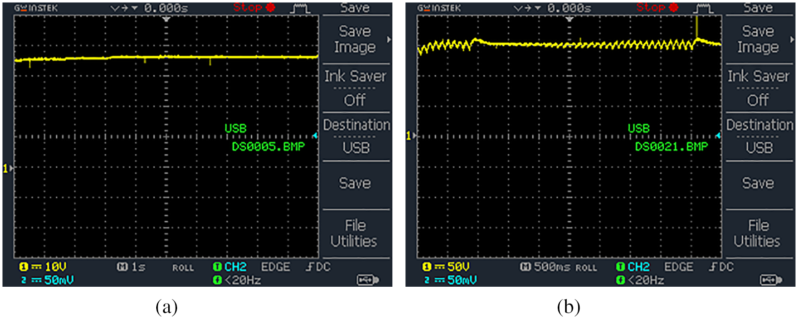
Figure 16: (a) & (b) Input DC voltage and current waveform
The converter’s output voltage waveform for CS-PI controller is depicted in Fig. 17. When comparing this waveform with conventional PI controller, the proposed converter reduces ripples, reduces maximum peak overshoot, decreases settling time and maintains constant voltage of
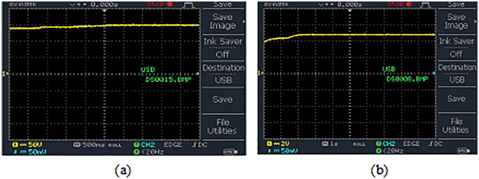
Figure 17: (a) Converter output voltage waveform for CS-PI controller (b) Output DC current waveform
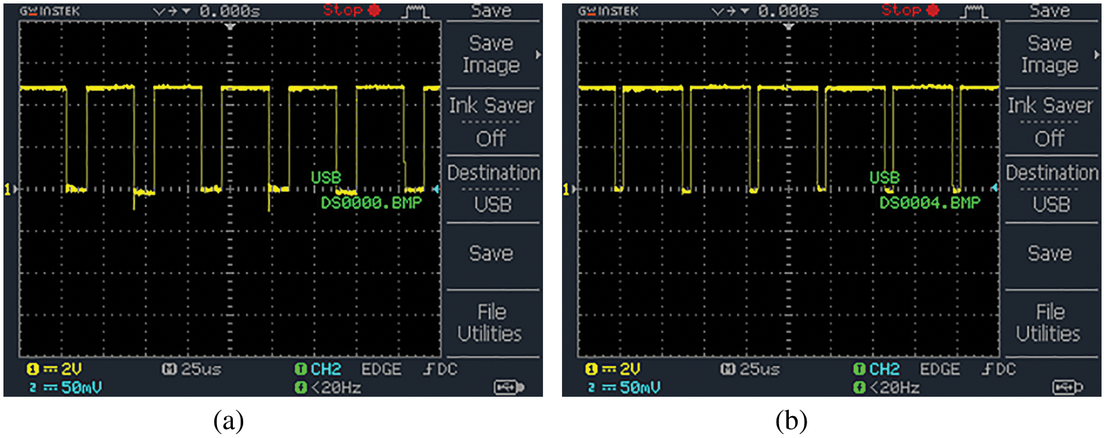
Figure 18: (a) & (b) Waveform for PWM pulses
The PWM pulses to the converter switches
The grid voltage and current waveforms are denoted in Fig. 19. The output of PI controller is combined with sine wave reference extracted from power grid and is given to reference power signal. The output current at inverter is chosen as reference from grid which precisely synchronizes with grid voltage.
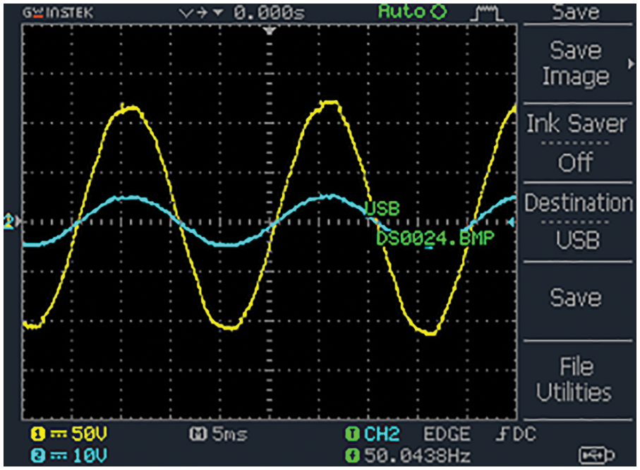
Figure 19: Grid voltage and current waveform
The comparison of efficiency is depicted in Fig. 20. The efficiency of improved SEPIC converter is compared with SEPIC and Boost. From this chart it shows that efficiency of improved SEPIC converter is
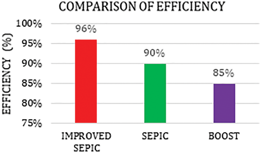
Figure 20: Comparison of efficiency
The comparison of gain is depicted in Fig. 21. The improved SEPIC converter’s gain is compared with SEPIC and Boost. From this chart it shows that the improved SEPIC converter’s gain is 1:12. It also shows that improved SEPIC converter’s performance is better than SEPIC and Boost converter.
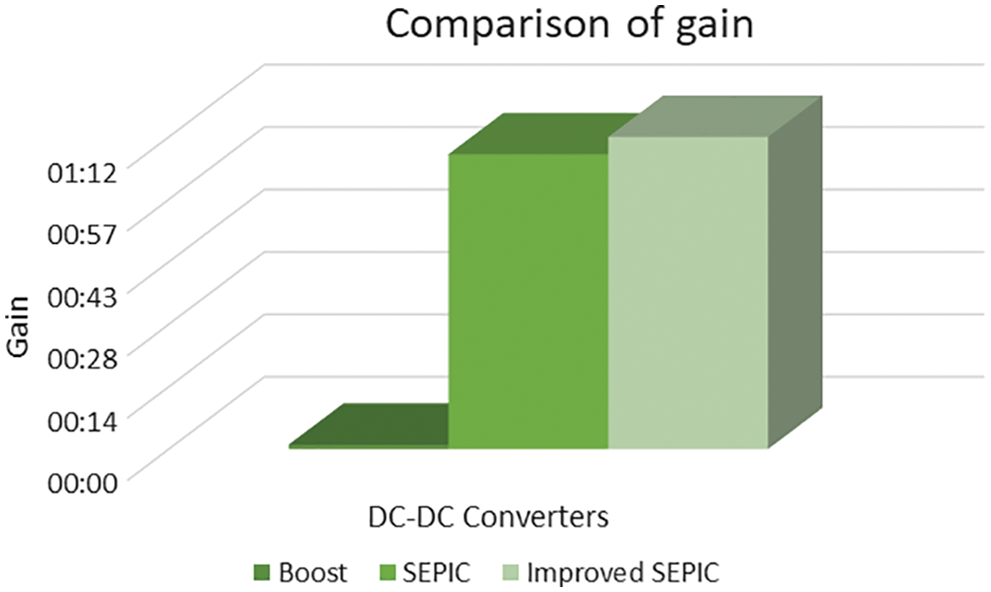
Figure 21: Comparison of gain
The THD comparison is illustrated in Fig. 22. The THD for CS-PI is compared with Fuzzy and PI. From this chart it shows that THD for CS-PI is
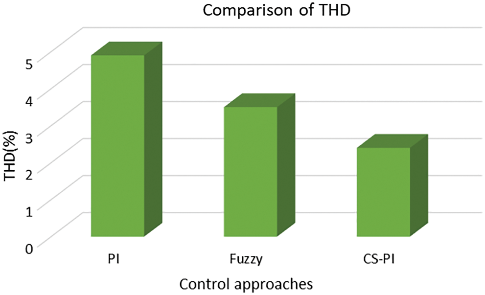
Figure 22: Comparison of THD
The THD for CS-PI and PI controller is given in Figs. 23a and 23b which reveals that the THD with CS-PI obtained is
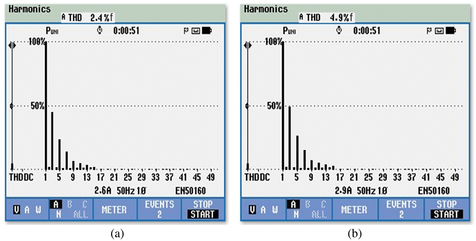
Figure 23: (a) & (b) THD with CS-PI and PI controller
This proposed system examines the dynamics and efficiency of control system against fluctuations that are common in all PV panels due to variation of temperature and intensity. An improved interleaved DC-DC SEPIC converter is employed. It overcomes the drawback of high input current ripples. It also provides excellent buck boost conversion ratio. When compared to other existing converters, the proposed converter consumes lesser components and provides improved energy efficiency. A crow search algorithm is utilized for proposed converter that optimizes the parameters of PI controller. The objective of CSA optimized PI controller of proposed converter is to generate good response and enables working in Continuous Conduction Mode (CCM). The performances improved with this optimization are reduction in ripples, decrease in settling time and minimization of peak overshoots. The obtained converter outputs are applied to a 1Ф VSI which in turn converts the DC input to AC output and supplies it to the gird. After implementing CSA based PI the efficiency of proposed converter obtained is
Funding Statement: The authors received no specific funding for this study.
Conflicts of Interest: The authors declare that they have no conflicts of interest to report regarding the present study.
References
1. N. Priyadarshi, M. S. Bhaskar, S. Padmanaban, F. Blaabjerg et al., “New CUK–SEPIC converter based photovoltaic power system with hybrid GSA–PSO algorithm employing MPPT for water pumping applications,” IET Power Electronics, vol. 13, no. 13, pp. 2824–2830, 2020. [Google Scholar]
2. O. Khan and W. Xiao, “An efficient modeling technique to simulate and control submodule integrated pv system for single-phase grid connection,” IEEE Transactions on Sustainable Energy, vol. 7, no. 1, pp. 96–107, 2016. [Google Scholar]
3. C. Olalla, C. Deline and D. Maksimovic, “Performance of mismatched pv systems with submodules integrated converters,” IEEE Journal of Photovoltaics, vol. 4, no. 1, pp. 396–404, 2014. [Google Scholar]
4. R. G. Wandhare and V. Agarwal, “Reactive power capacity enhancement of grid system to increase pv generation level in smart grid scenario,” IEEE Transactions on Smart Grid, vol. 5, no. 4, pp. 1845–1854, 2014. [Google Scholar]
5. N. Arab, B. A. Javadi and K. A. Haddad, “A multifunctional single phase grid integrated residential solar pv systems based on LQR control,” IEEE Transactions on Industry Applications, vol. 55, no. 2, pp. 2099–2109, 2019. [Google Scholar]
6. S. Pradhan, I. Hussain, B. Singh and B. K., Panigrahi, “Modified VSS-LMS based adaptive control for improving the performance of a single state pv integrated grid system,” IET Science, Measurement & Technology, vol. 11, no. 4, pp. 388–399, 2017. [Google Scholar]
7. C. Jain and B. Singh, “Single-phase single-stage multifunctional grid interfaced solar photo-voltaic system under abnormal grid conditions,” IET Generation, Transmission & Distribution, vol. 9, no. 10, pp. 886–894, 2015. [Google Scholar]
8. B. N. Alajmi, K. H. Ahmed, G. P. Adam and B. W. Williams, “Single-phase single-stage transformer less grid-connected pv system,” IEEE Transactions on Power Electronics, vol. 28, no. 6, pp. 2664–2676, 2013. [Google Scholar]
9. A. Darwish, S. Alotaibi and M. A. Elgenedy, “Current source single phase module integrated inverters for pv grid connected applications,” IEEE Access, vol. 8, pp. 53082–53096, 2010. [Google Scholar]
10. M. Forouzesh, Y. Shen, K. Yari, Y. P. Siwakoti and F. Blaabjerg, “High efficiency high step up DC-DC converter with dual coupled inductors for grid connected photovoltaic system,” IEEE Transactions on Power Electronics, vol. 33, no. 7, pp. 5967–5982, 2018. [Google Scholar]
11. M. Das and V. Agarwal, “Design and analysis of DC converter with soft switching capability for renewable energy application requiring high voltage gain,” IEEE Transactions on Industrial Electronics, vol. 63, no. 5, pp. 2936–2944, 2016. [Google Scholar]
12. M. Lakshmi and S. Hemamalini, “Coordinated control of MPPT and voltage regulation using single-stage high gain DC–DC converter in a grid-connected PV system,” Electric Power Systems Research, vol. 169, pp. 65–73, 2019. [Google Scholar]
13. K. Sayed, M. G. Gronfula and H. A. Ziedan, “Novel soft-switching integrated boost DC-DC converter for PV power system,” Energies, vol. 13, no. 3, pp. 749, 2020. [Google Scholar]
14. E. Mamarelis, G. Petrone and G. Spagnuolo, “Design of a sliding mode controlled SEPIC for pv MPPT application,” IEEE Transactions on Industrial Electronics, vol. 61, no. 7, pp. 3387–3398, 2014. [Google Scholar]
15. M. Vaigundamoorthi, R. Ramesh, V. V. Prabhu and K. A. Kumar, “MPPT oscillations minimization in PV system by controlling non-linear dynamics in SEPIC DC-DC converter,” International Journal of Electrical and Computer Engineering, vol. 10, no. 6, pp. 6268–6275, 2020. [Google Scholar]
16. J. Manohar and K. S. Rajesh, “A comparative study and performance analysis of synchronous seplc converter and synchronous zeta converter by using pv system with MPPT technique,” in IEEE Int. Conf. on Power Electronics, Intelligent Control and Energy Systems, Delhi, India, pp. 1–6, 2016. [Google Scholar]
17. K. Kavitha and E. Jeyakumar, “A synchronous cuk converter based photovoltaic energy system design and simulation,” International Journal of Scientific and Research Publications, vol. 2, no. 10, pp. 1–8, 2012. [Google Scholar]
18. K. Nathan, S. Ghosh, Y. Siwakoti and T. Long, “A new DC-DC converter for photovoltaic systems: Coupled inductors combined CUK-SEPIC converter,” IEEE Transactions on Energy Conversion, vol. 34, pp. 191–201, 2019. [Google Scholar]
19. R. A. Barbosa, D. A. Souza and A. P. N. Tahim, “Adaptive control of DC micro grid using PI controller and fuzzy inference,” IEEE PES Innovative Smart Grid Technologies Conference, Gramado, Brazil, pp. 1–6, 2019. [Google Scholar]
20. A. E. Khateb, N. A. Rahim, J. Selvaraj and M. N. Uddin, “Maximum power point tracking of single ended primary inductor converter employing a novel optimization technique for proportional integral derivative controller,” IET Power Electronics, vol. 6, no. 6, pp. 1111–1121, 2013. [Google Scholar]
21. A. E. Khateb, N. A. Rahim, J. Selvaraj and M. N. Uddin, “Fuzzy-logic-controller-based sepic converter for maximum power point tracking,” IEEE Transactions on Industry Applications, vol. 50, no. 4, pp. 2349–2358, 2014. [Google Scholar]
22. S. Mohanty, B. Subudhi and P. K. Ray, “A new MPPT design using grey wolf optimization technique for photovoltaic system under shading conditions,” IEEE Transactions on Sustainable Energy, vol. 7, no. 1, pp. 181–188, 2016. [Google Scholar]
23. M. Hussein, K. R. Mahmoud, M. F. O. Hameed and S. S. Obayya, “Optimal design of vertical silicon nanowires solar cell using hybrid optimization algorithm,” Journal of Photonics for Energy, vol. 8, no. 2, pp. 022502, 2017. [Google Scholar]
24. N. Kumar, I. Hussain, B. Singh and B. K. Panigrahi, “Framework of maximum power extraction from solar pv panel using self-predictive perturb and observe algorithm,” IEEE Transactions on Sustainable Energy, vol. 9, no. 2, pp. 895–903, 2018. [Google Scholar]
25. R. B. A. Koad, A. F. Zobaa and A. E. Shahat, “A novel MPPT algorithm based oh particle swarm optimization for photovoltaic systems,” IEEE Transactions on Sustainable Energy, vol. 8, no. 2, pp. 468–476, 2017. [Google Scholar]
Cite This Article
 Copyright © 2023 The Author(s). Published by Tech Science Press.
This work is licensed under a Creative Commons Attribution 4.0 International License , which permits unrestricted use, distribution, and reproduction in any medium, provided the original work is properly cited.
 Downloads
 Citation Tools