
 Submit a Paper
 Propose a Special lssue
 Open Access
ARTICLE

A Chaotic Pulse Train Generator Based on Henon Map
1 College of Engineering, Trivandrum, 695016, India
2 Government Engineering College, Barton Hill, Trivandrum, 695035, India
3 APJ Abdul Kalam Technological University, Trivandrum, 695016, India
* Corresponding Author: Babu H. Soumya. Email:
Intelligent Automation & Soft Computing 2023, 37(1), 1197-1207. https://doi.org/10.32604/iasc.2023.031575
Received 21 April 2022; Accepted 17 August 2022; Issue published 29 April 2023
 View Full Text
 Download PDF
Abstract
The Henon map forms one of the most-studied two-dimensional discrete-time dynamical systems that exhibits chaotic behavior. The Henon map takes a point in the plane and maps it to a new point . In this paper, a chaotic pulse generator based on the chaotic Henon map is proposed. It consists of a Henon map function subcircuit to realize the Henon map and another subcircuit to perform the iterative operation. The Henon map subcircuit comprises operational amplifiers, multipliers, delay elements and resistors, whereas, the iterative subcircuit is implemented with a simple design that comprises of an edge forming circuit followed by a monostable multivibrator and a voltage controlled switch without the use of any clock control. The proposed design can be used to realize the Henon map and also to generate a chaotic pulse train, with a controllable time interval and pulse position. The proposed circuit is implemented and simulated using Multisim 13.0 and MATLAB R2019b. The chaotic nature of the generated pulse train and also the time interval between the consecutive pulses is verified by the calculation of its Lyapunov exponents.Keywords
Chaotic systems are deterministic nonlinear dynamical systems that consist of a set of possible states, together with a rule that determines the present state in terms of past states. It is required that the rule be deterministic, to uniquely determine the present state from the past states. When the governing rule is applied at discrete times, it is a discrete-time dynamical system or the so-called iterated maps and when the rule is a set of differential equations, it is a continuous-time dynamical system [1]. These systems are characterized by high sensitivity to initial conditions, presence of dense orbits and must be topologically transitive, which makes the system output completely different for even a very small change in the input applied to the system [2]. A chaotic map or the so-called iterated map is an evolution function exhibiting chaotic behavior, and can be parameterized by a discrete-time or a continuous-time parameter. It mostly takes the form of iterative functions and can be one-dimensional, two-dimensional or multi-dimensional. But much attention is given to one-dimensional and two-dimensional quadratic mappings, as they exhibit all the interesting properties a map can have.
Such pseudo-random behavior of chaotic systems makes these systems highly regarded for various applications like pseudo-random sequence generation, encryption and secure communication. Moreover, these systems are extensively used for the generation of chaotic signals and chaotic pulse train, that can be used as a control signal and modulating signal, and has several applications in cryptography [3], data processing [4], secure communication [5], steganography [6], bio-medical processing and its extended applications [7,8].
Several works have been done in the past for the generation of chaotic pulse train. In 2008, Wang et al. introduced a method to generate chaotic pulse sequence by chaotic phase trajectory [9]. In 1994, Balmforth et al. found that under certain particular conditions, the third-order nonlinear ODE can take the form of a chaotic pulse sequence [10]. Later in 2005, methods were proposed for generating chaotic pulse for reaction-diffusion systems, mainly focused on algorithm implementation and not appropriate for circuit implementation [11]. Dmitriev et al. in 2005 proposed a method to generate the chaotic pulse trains using a dynamical system that uses a periodic signal [12]. In most of these dynamic systems with circuits implemented by resistors, capacitors, monostable multivibrators, analog switches etc. one–dimensional return maps are used. But in these methods, it is difficult or not possible to control the generated pulse parameters like pulse position, pulse interval etc. The major drawback of such a realization is the requirement of an external control signal to drive the circuits and the difficulty in controlling various parameters such as pulse width and frequency of the generated chaotic pulse sequence. In the last decade, another one-dimensional piecewise linear map referred to as the Tent map has been used extensively in these applications [13,14] and such circuit implementations [15,16]. In 2000, Tanaka et al. proposed the voltage mode based integrated circuits of Logistic map and Tent map chaotic generators [17]. In 2009, Campos-Canton et al. proposed a voltage mode based electronic circuit to implement the Tent map [18]. Though these circuits are easy to implement, chaotic pulse sequence could not be produced. Later in 2015, Zhang et al. proposed a chaotic pulse generator based on the Tent map which overcomes the drawbacks of the previous methods and can be used for the generation of chaotic pulse sequence with control over the pulse parameters [19].
However, this article proposes the implementation of a chaotic pulse train based on a two-dimensional chaotic map referred to as the Henon map. In past literatures, only a few one-dimensional chaotic maps like logistic map, Tent map etc. have been realized and analyzed for such applications [18,20,21]. But, very few works have been done to realize the two-dimensional iterated maps, and analyze its chaotic and complex dynamics [22,23]. Even though all the circuits mentioned in these literatures can be used to generate chaotic series, and some of them are even easy to implement, since these methods use periodic clock signals to implement the iterative process, the chaotic pulse train or sequence may not be produced. This article deals with the implementation of a circuit to realize the Henon map and thus generate two sets of chaotic time series and also to generate the chaotic pulse sequence with a control on the pulse parameters like pulse interval and pulse position. Also, the entire circuit is realized more concisely compared to the existing literatures and has a reasonable design without any clock control.
The Henon map forms one of the most studied two-dimensional discrete-time dynamical systems that exhibit chaotic behavior. It was introduced as a simplified model of the Poincare section of Lorenz model [24]. Due to its simple form and interesting chaotic behaviors, the map has always been attractive as a mathematical model to study deterministic chaos. The map takes a point
This article focuses on the circuit implementation of a chaotic pulse generator. A 2-D chaotic Henon map based chaotic pulse train generator is proposed, which does not require an external control signal. The design of the proposed circuit consists of mainly two parts (A) Henon map subcircuit realization (B) a circuit to realize the iterative operation. The Henon map subcircuit realization is done more precisely compared to the ones in the existing literatures whereas, the iterative subcircuit is implemented with a simple design without any clock control. Instead of using an external control signal, an edge signal forming circuit is designed to generate a positive and negative edge signal that, in turn, triggers a monostable multivibrator (MM). Upon triggering, a pulse signal is generated at the output of the MM, which is used to close an analog switch that passes the output of the Henon map to its input.
Fig. 1 shows the overall block diagram of the proposed circuit. It consists of a simple circuit designed to set initial condition for the Henon map, followed by a circuit to realize the Henon map. The Henon map realization is followed by an iterative subcircuit which feeds back the iterated output of the Henon map so that, it serves as the next input to the Henon map.
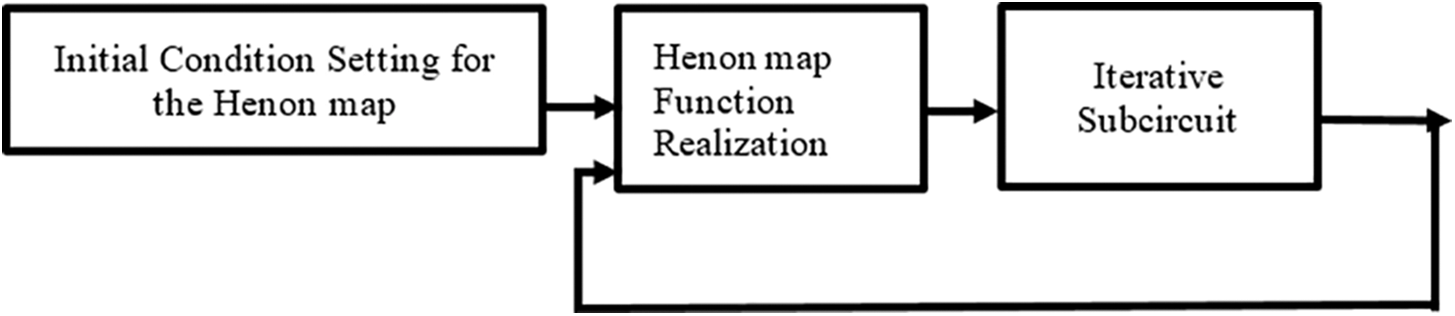
Figure 1: Block diagram of the proposed circuit
2.1 Henon Map Function Subcircuit
The Henon map function takes a point
Fig. 2 shows the circuit diagram of the proposed subcircuit of the Henon map. The Henon map is realized using an operational amplifier U3A, four resistors R2 to R5, two multipliers A1 and A2, a delay element A3 and power supplies. Two multipliers A1 and A2 are used to set the values of the parameters ‘

Figure 2: Circuit diagram of the Henon map subcircuit realization
The closed-loop gain of the summing amplifier is given by
In this article, an ingenious design consisting of an edge signal forming circuit, a switch and a monostable multivibrator (MM) is used to develop a circuit that performs an iterative operation as described in the Fig. 3. The edge signal generated is used to trigger the MM, that in turn produces the pulse signal at its output. This pulse output from the MM is used as control signal to control the analog switch, that pass on the signal
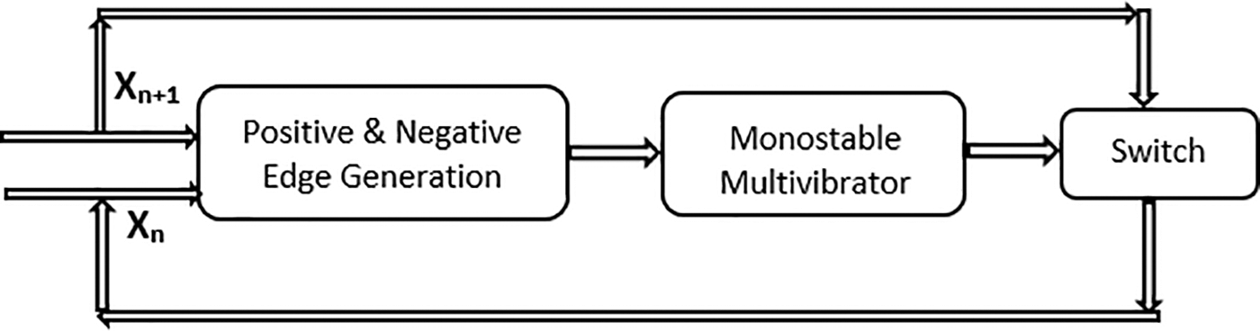
Figure 3: Flow diagram of the proposed iterative operation
The overall circuit diagram of the proposed circuit to generate the chaotic pulse train is shown in the Fig. 4. It consists of a simple circuit to set the initial condition of the Henon map followed by the Henon map realization subcircuit, a comparator circuit using LM311D, a monostable multivibrator CD4538BCM and a voltage-controlled SPST switch S2.
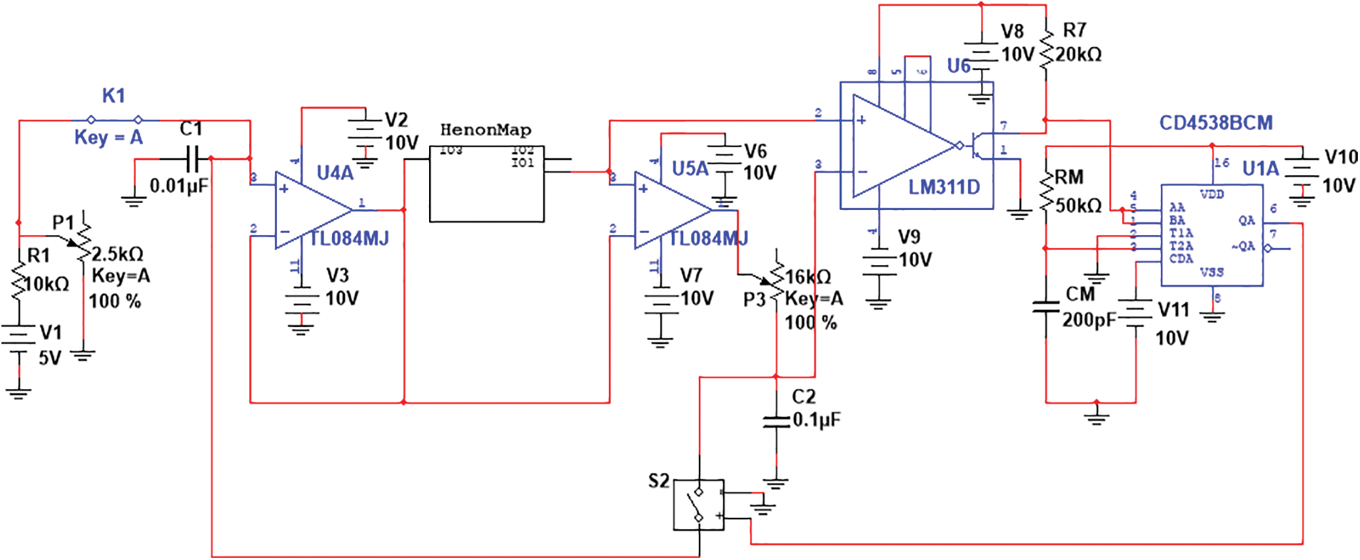
Figure 4: Overall circuit diagram of the proposed circuit
The initial condition
In the implementation of the iterative circuit, the design of the edge forming circuit forms the crucial part. It is implemented by making use of an operational amplifiers U5A, a comparator U6 using LM311D, a switch S2, a capacitor
When
Since both positive and negative triggering are used to trigger the monoshot CD4538BCM IC, a dual precision monostable multivibrator is chosen for the circuit, which has two triggering inputs to enable both rising and falling edge triggering. The time period of the output pulse of the MM is controllable with the use of external resistor
The time interval between the
In this case, when
where
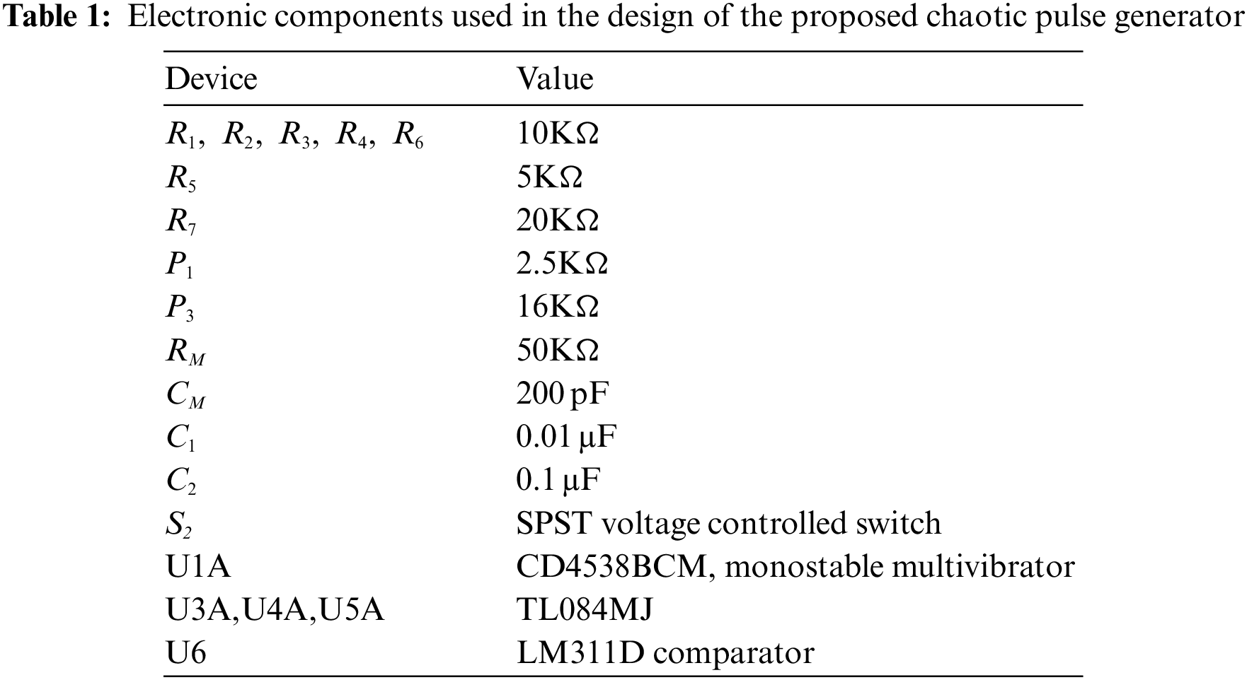
Table 1 summarizes the various components and devices used in the circuit along with its values. First step is the setting of an appropriate value of initial condition for the Henon map in the range [0, 1] by suitably adjusting the values of the potentiometer
Figs. 5a and 5b shows the chaotic waveforms generated from the Henon map, realized with bifurcating parameters
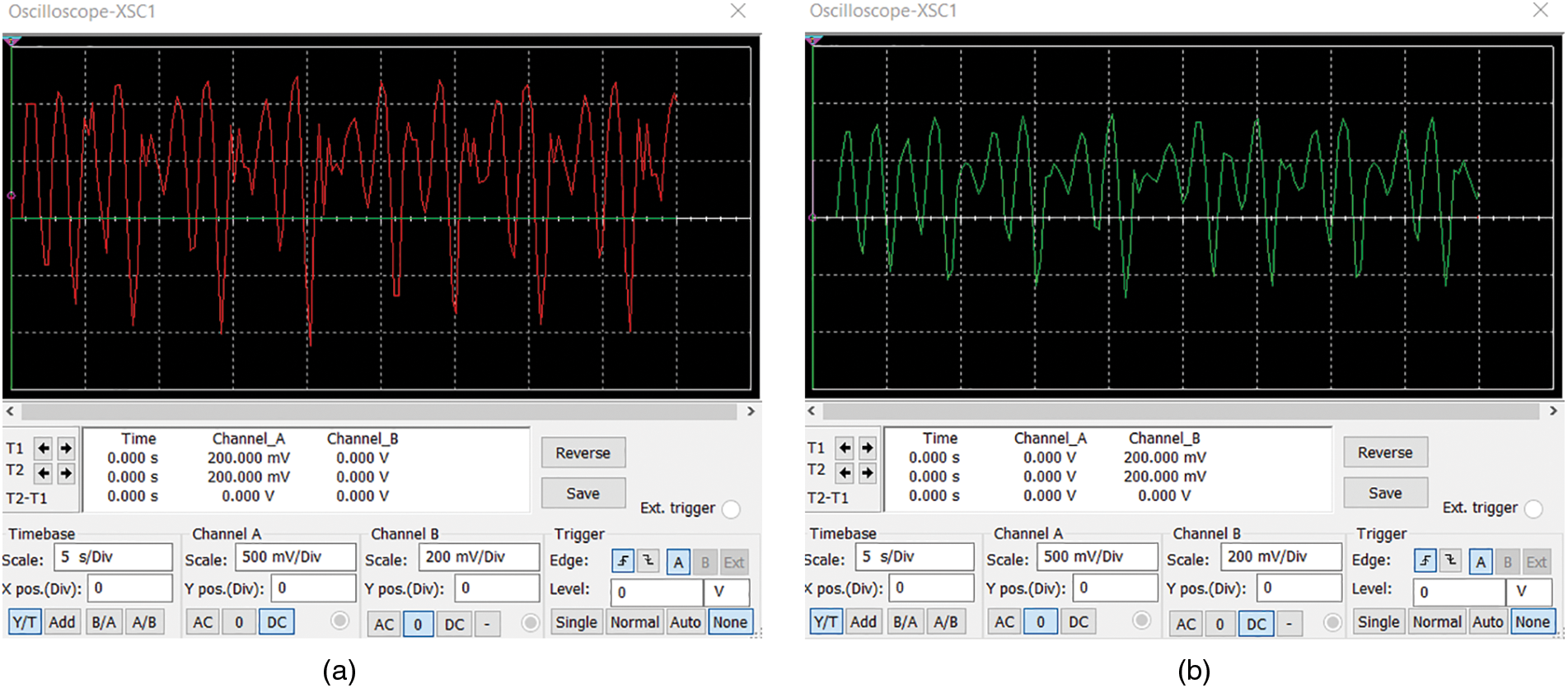
Figure 5: The chaotic waveforms
Fig. 6 shows the Henon attractor obtained from the simulated results

Figure 6: The Henon map attractor obtained from the simulated results of
The influence of the potentiometer P3 on the time period of the chaotic series generated is indicated in Fig. 7. It show the waveforms of the Henon map series
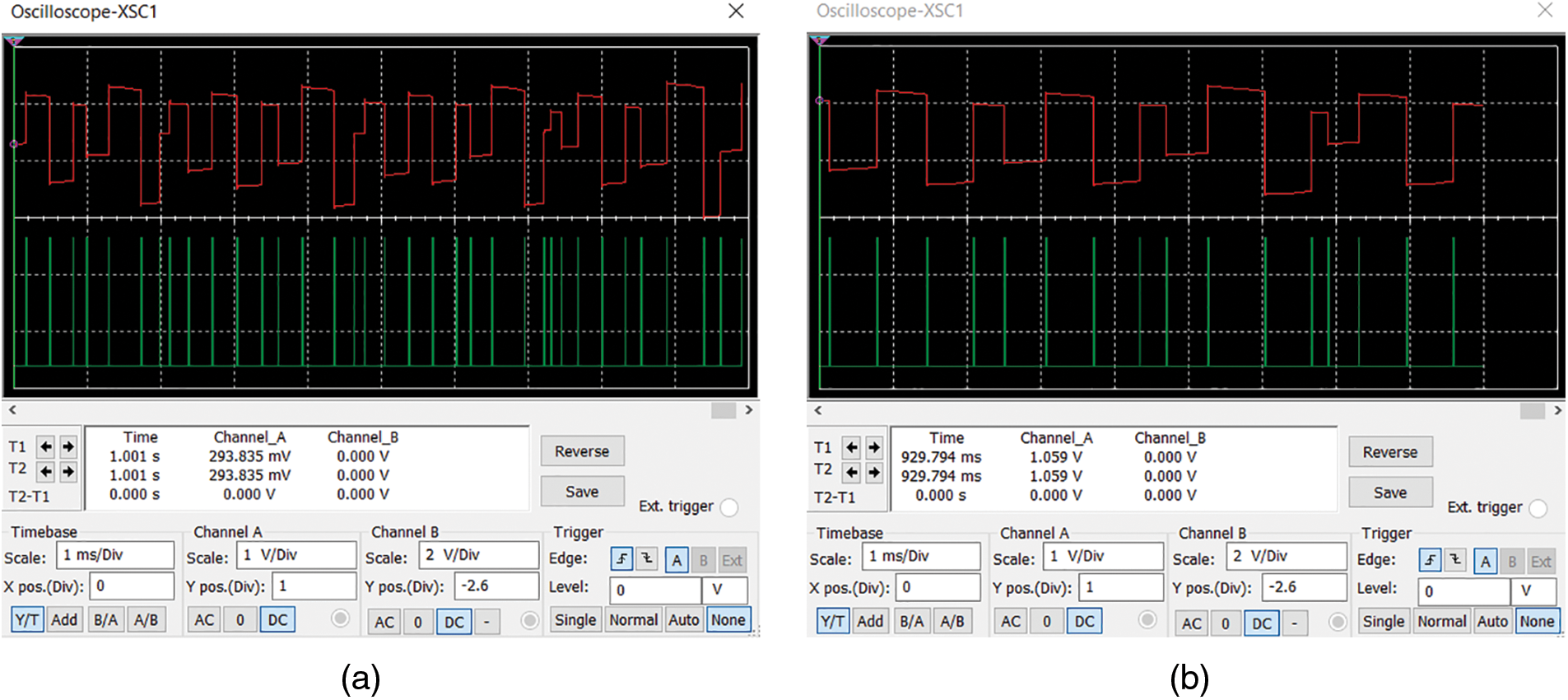
Figure 7: The waveforms of Henon map series Xn (red) and chaotic pulse train
The chaotic nature of the pulse train generated from the MM can be verified by calculating its Lyapunov exponents [31]. The Lyapunov exponents provide a quantitative as well as qualitative characterization of dynamical systems and are also related to the nearby orbit’s quick divergence or convergence in phase space. The Lyapunov exponents of a discrete-time dynamical system
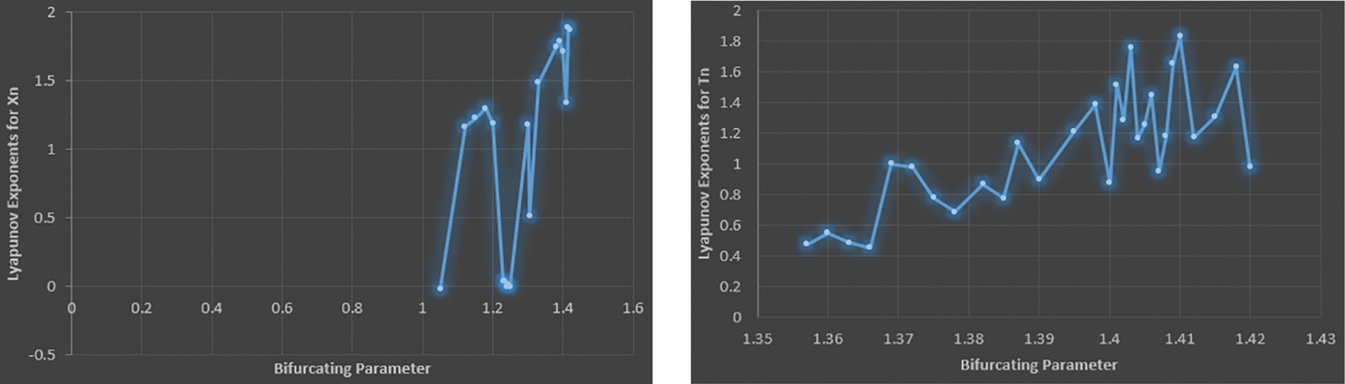
Figure 8: (a, b) Plot of Lyapunov Exponents calculated for
5 Comparison with Other Benchmark Algorithms
In the electronic circuit designed, simulated and analyzed in the article, less number of components are utilized to implement the overall circuit thus, when compared to other benchmark circuits, the overall circuit is more concisely realized. The same circuit can be used to realize the Henon map and also to generate two sets of chaotic series and a chaotic pulse train. Moreover, the position and time interval of the generated chaotic pulse are controllable by varying the variable components used in the design. Another important feature of the design is the implementation of a circuit to perform iterative operation. To implement an iterative operation, a reasonable design comprising an edge forming circuit, analog switch and monostable multivibrator is employed which eliminates the need of a periodic clock control in contrast to existing works.
In this article, a two-dimensional Henon map based chaotic sequence and pulse generator is proposed. The designed and simulated circuit can be used to realize the Henon map function and also to generate two sets of chaotic sequences and a chaotic pulse train. The proposed circuit is simple since less number of components are used to implement the system. The circuit is designed using various electronic components such as operational amplifier, comparator, monostable multivibrator, analog switch and other passive components. The key feature of this realization is that the generated chaotic pulse train from the monoshot multivibrator can be controlled in terms of pulse interval and also pulse position, by changing the values of various electronic components used in the circuit. The chaotic nature of both, the generated pulse train and the time interval between the consecutive pulses, is verified by its calculated positive Lyapunov exponents and plotted against the bifurcating parameter.
Funding Statement: The authors received no specific funding for this study.
Availability of Data and Materials: The data used to support the findings of the study are available from the corresponding author upon request.
Conflicts of Interest: The authors declare that they have no conflicts of interest to report regarding the present study.
References
1. K. T. Alligood, T. D. Sauer and J. A. Yorke, “One-dimensional maps,” in CHAOS An Introduction to Dynamical Systems, 1st ed., vol. 1. New York: Springer-Verlag, pp. 1–3, 1997. [Google Scholar]
2. J. Banks, J. Brooks, G. Cairns, G. Davis and P. Stacey, “On devaney’s definition of chaos,” The American Mathematical Monthly, vol. 99, no. 4, pp. 332–334, 1992. [Google Scholar]
3. H. J. Gao, Y. S. Zhang, S. Y. Liang and D. Q. Li, “A new image encryption algorithm based on hyper-chaos,” Solitons and Fractals, vol. 29, no. 12, pp. 393–399, 2006. [Google Scholar]
4. H. Torikai, T. Saito and W. Schwarz, “A chaotic pulse generator and sawtooth control for information processing,” in Proc. IEEE Int. Symp. on Circuits and Systems (ISCAS), Hong Kong, China, pp. 729–735, 1997. [Google Scholar]
5. Z. J. Yao, Q. H. Meng, G. W. Li and P. Lin, “Non-crosstalk real-time ultrasonic range system with optimized chaotic pulse position-width modulation excitation,” in Proc. IEEE Ultrasonics Symp. (IUS), Beijing, China, pp. 729–732, 2008. [Google Scholar]
6. X. Liao, Y. Yu, B. Li, Z. Li and Z. Qin, “A new payload partition strategy in color image steganography,” IEEE Transactions on Circuits and Systems for Video Technology, vol. 30, no. 3, pp. 685–696, 2020. [Google Scholar]
7. T. -L. Liao, H. -C. Chen, C. -Y. Peng and Y. -Y. Hou, “Chaos-based secure communications in biomedical information application,” Electronics, vol. 10, pp. 359–379, 2021. [Google Scholar]
8. A. Hobiny, F. Alzahrani, I. Abbas and M. Marin, “The effect of fractional time derivative of bioheat model in skin tissue induced to laser irradiation,” Symmetry, vol. 12, no. 4, Article No. 602, pp. 1–10, 2020. [Google Scholar]
9. Y. W. Wang, L. P. Wang, S. Yu, L. Zhang, D. M. Yan et al., “Chaotic pulses for diffusion systems,” in Proc. Int. Conf. on Signal Processing (ICSP), Beijing, no. 7, pp. 1892–1896, 2008. [Google Scholar]
10. N. J. Balmforth, G. R. Ierley and E. A. Spiegel, “Chaotic pulse trains,” SIAM Journal on Applied Mathematics, vol. 54, no. 5, pp. 129–134, 1994. [Google Scholar]
11. Y. Nishiura, D. Ueyama and T. Yanagita, “Chaotic pulses for discrete reaction diffusion systems,” SIAM Journal on Applied Dynamical Systems, vol. 4, no. 3, pp. 733–754, 2005. [Google Scholar]
12. A. S. Dmitriev, E. V. Efremova and L. V. Kuz’min, “Chaotic pulse trains generated by a dynamical system driven by a periodic signal,” Technical Physics Letters, vol. 11, no. 33, pp. 961–963, 2005. [Google Scholar]
13. T. Addabbo, M. Alioto, A. Fort, S. Rocchi and V. Vignoli, “The digital tent map: Performance analysis and optimized design as a low-complexity source of pseudorandom bits,” IEEE Transactions on Instrumentation and Measurement, vol. 55, no. 5, pp. 1451–1458, 2006. [Google Scholar]
14. Y. Wang, K. W. Wong, X. F. Liao and T. Xiang, “A block cipher with dynamic S-boxes based on Tent map,” Communications in Nonlinear Science and Numerical Simulation, vol. 14, no. 7, pp. 3089–3093, 2009. [Google Scholar]
15. J. T. Bean and P. J. Langlois, “A current mode analog circuits for Tent maps using piecewise linear functions,” in Proc. IEEE Int. Symp. on Circuits and Systems (ISCAS), London, UK, vol. 6, pp. 125–129, 1994. [Google Scholar]
16. P. Dudek and V. D. Juncu, “Compact discrete-time chaos generator circuit,” Electronics Letters, vol. 39, no. 20, pp. 1431–1432, 2003. [Google Scholar]
17. H. Tanaka, S. Sato and K. Nakajima, “Integrated circuits of map chaos generators,” Analog Integrated Circuits and Signal Processing, vol. 25, no. 3, pp. 329–335, 2000. [Google Scholar]
18. I. Campos-Canton, E. Campos-Canton, J. S. Murguia and C. Rosu, “A simple circuit realization of the Tent map,” Chaos, Solitons & Fractals, vol. 42, no. 1, pp. 12–16, 2009. [Google Scholar]
19. T. -F. Zhang, S. -L. Li, R. -J. Ge, M. Yuan, G. Gui et al., “A chaotic pulse sequence generator based on the Tent map,” IEICE Electronics Express, vol. 12, no. 16, pp. 1–10, 2015. [Google Scholar]
20. E. D. M. Hernandez, G. Lee and N. H. Farhat, “Analog realization of arbitrary one-dimensional maps,” IEEE Transactions on Circuits System I:Fundamental Theory Applications, vol. 50, no. 12, pp. 1538–1547, 2003. [Google Scholar]
21. M. Suneel, “Electronic circuit realization of the Logistic map,” Sadhana, vol. 31, no. 1, pp. 1–14, 2006. [Google Scholar]
22. M. Garcia-Martinez, I. Campos-Canton, E. Campos-Canton and S. Celikovsky, “Difference map and its electronic circuit realization,” Nonlinear Dynamics, vol. 73, pp. 819–830, 2013. [Google Scholar]
23. O. O. Aybar, I. K. Aybar and A. S. Hacinliyan, “Stability and bifurcation in the Henon map and its generalizations,” Chaotic Modeling and Simulation (CMSIM), vol. 4, pp. 529–538, 2013. [Google Scholar]
24. J. F. Heagy, “A physical interpretation of the H´enon map,” Physica. D, vol. 57, no. 3, pp. 436–446, 1992. [Google Scholar]
25. M. Henon, “A two–dimensional mapping with a strange attractor,” Communications in Mathematical Physics, vol. 50, no. 1, pp. 69–77, 1976. [Google Scholar]
26. F. R. Marotto, “Chaotic behaviour in the Henon mapping,” Communications in Mathematical Physics, vol. 68, no. 2, pp. 187–194, 1979. [Google Scholar]
27. W. F. H. Al-Shameri, “Dynamical properties of the H´enon mapping,” International Journal of Mathematical Analysis, vol. 6, no. 49, pp. 2419–2430, 2012. [Google Scholar]
28. M. Cai, “Complex dynamics in generalized Henon map,” Discrete Dynamics in Nature and Society, vol. 2015, Article ID 270604, pp. 1–18, 2015. [Google Scholar]
29. D. Chattopadhyay and P. C. Rakshit, Electronics Fundamentals and Applications, 12th ed., New Delhi: New Age International (P) Limited Publishers, pp. 336–339, 2014. [Google Scholar]
30. K. Gopakumar, “Capacitor,” in Design and Analysis of Electronic Circuits, 2nd ed., Kollam: Phasor Books, pp. 2–4, 2004. [Google Scholar]
31. M. Sano and Y. Sawada, “Measurements of the Lyapunov spectrum from chaotic time series,” Physical Review Letters, vol. 55, no. 10, pp. 1082–1085, 1985. [Google Scholar] [PubMed]
32. A. Wolf, J. B. Swift, H. L. Swinney and J. A. Vastano, “Determining Lyapunov exponents from a time series,” Physica D:Nonlinear Phenomena, vol. 16, no. 3, pp. 285–317, 1985. [Google Scholar]
33. A. Dabrowski, T. Sagan, V. Denysenko, M. Balcerzak, S. Zarychta et al., “Alternative methods of the largest lyapunov exponent estimation with applications to the stability analyses based on the dynamical maps—Introduction to the method,” Materials, vol. 14, no. 23, pp. 7197–7212, 2021. [Google Scholar] [PubMed]
Cite This Article
 Copyright © 2023 The Author(s). Published by Tech Science Press.
This work is licensed under a Creative Commons Attribution 4.0 International License , which permits unrestricted use, distribution, and reproduction in any medium, provided the original work is properly cited.
 Downloads
 Citation Tools