 Open Access
ARTICLE
Study of the Neutron Radiation Effect on Bi-oriented Polyethylene Naphthalate Structure
1
Laboratory of Materials Physics, Faculty of Physics, University of Sciences and Technology
- Houari Boumediene (U.S.T.H.B.), El-Alia, Bab-Ezzouar, DZ-16111 Algiers, Algeria.
2
Laboratory of Hydrometallurgy and Inorganic Molecular Chemistry, Faculty of Chemistry,
University of Sciences and Technology - Houari Boumediene (U.S.T.H.B.), El-Alia,
Bab-Ezzouar, DZ-16111 Algiers, Algeria.
3
High National School of Veterinary, DZ-16111 Algiers, Algeria.
4
Draria Nuclear Research Center, Sebala, Draria, DZ-16000 Algiers, Algeria.
* Corresponding Author: e-mail:
Journal of Polymer Materials 2022, 39(1-2), 1-15. https://doi.org/10.32381/JPM.2022.39.1-2.1
Abstract
In this work, neutron induced structural modifications, on the biaxially-oriented polyethylene naphthalate (BOPEN) film, were studied by X-ray diffraction technique (XRD), Fourier transform infrared spectroscopy (FTIR/ATR), scanning electron microscopy (SEM) and polarized light optical microscopy (PLOM). The irradiation with neutron was carried out, under air, at room temperature. The changes of the structure, in volume and in surface were evaluated under the impact of neutron’s flux composed by thermally neutrons and fast neutrons. The X-ray technique showed the effect of the neutron flux’s fluence on the crystallinity of the BOPEN, which was also determined through the FTIR/ATR spectroscopy, traduced by the absence and (or) presence of the absorption bands characteristics of crystalline and amorphous phases. The SEM and PLOM characterizations, revealed a radical change in the texture of the surface which passes from an orderly homogeneous state, observed on the NIR-BOPEN film, to a degraded state, shown up in irradiated samples (IR-BOPEN) case.Keywords
Polymer films are used in different activities like as the building, cosmetic, medical devices and also in nuclear industry domain. In this latest application, plastic materials have known an important use that took birth with the construction of the first nuclear power plants[1–3]. It was proven that, polyethylene naphthalate (PEN) is a potential candidate as an organic scintillator for radiation detection[4]. This in reason of its high density, its high scintillation yield, and its short photoluminescence decay time. Furthermore, polyethylene naphthalate is easy to manipulate and its price is lower than that of commercialized organic scintillators[5–9].
The polyethylene naphthalate, or yet poly(ethylene-2,6-naphthalenedicarboxylate), with macromolecular atomic composition [C14H10O4]n, is a linear thermoplastic polyester. Its repeating unit, indicated in figure 1, contains a naphthalene group which leads to a stronger rigidity of the macromolecular chain. In this configuration, the carbon-oxygen bonds of the carbonyl group of the π-type, are separated from the naphthalene group by, only, a simple bond. The conjugation of the aromatic system extends up the carbonyl groups. This delocalization of the π electrons are accompanied by a modification of the valence distances of certain bonds; to know: the extension of the C=O bond, a shortening of the C-O bond and a narrowing of the distance between carboxylic and aromatic carbons[10].
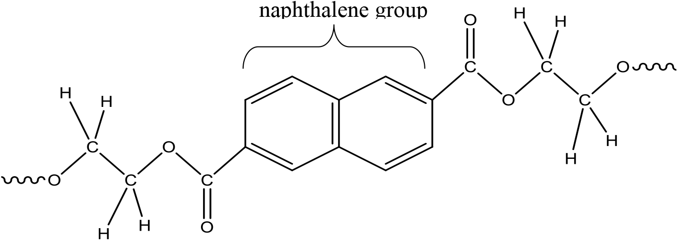
Figure 1.: General formula of monomer unit of PEN
Macromolecules of polyethylene naphthalene crystallize in two types of networks. The low temperature or α-network mode crystallizes at a temperature of 160°C from the fade, while the α-network mode crystallizes at a temperature of 245°C from the fade. The fade, is obtained at a temperature above 280°C.
The ionizing radiation damage on polymers has made the subject of much scientific researches and many articles have been published on this subject. Such studies are of importance for understand the behavior of materials apt for a using in radioactive environments, such as in nuclear power plants, in the sterilization of polymeric medical disposables or of food plastic packaging.
During irradiation by either swift heavy ions, fast electrons or high energy photons, a large quantity of energy is transferred to the polymeric molecules. These last causes some chemical degradation such as the breaking of the main chains of the macromolecule, changes in the number and nature of double bonds, and the emission of low molecular weight gaseous products, as well as oxidation of the polymer[11–22]. All these phenomena coexist and their predominance depending upon the chemical structure of the polymer, and the conditions of irradiation.
The response of polyethylene naphthalate to ionizing radiation has been studied by several researchers[23–28]. In the majority of these works, except the study carried out by K. Devgan et al.,[27], only, the correlation between the radiation type delivered and the physical properties of PEN, such as the photoluminescent and dielectric properties, has been highlighted but without taking into account the nature and the rate of the damage that undergoes this polyester film during tests irradiation undertaken.
In this work, the effect of neutron radiation is studied. The aim of this research is to determine the impact of the irradiation on the morphology and chemical structure of the PEN film by different structural analysis and to evaluate of the damage caused by the irradiation by varying the value of the neutron fluence delivered during irradiation.
The PEN used in this work, Teonex® Q51 type, was provided by DuPont Teijin Films (Luxembourg). It is a biaxially oriented PEN film (BOPEN) produced by a stenter process.
The irradiations were performed at Algiers's NUR research reactor at temperature equal to 40°C. The samples were separately inserted in a well-sealed container made of aluminum in order to minimize the neutron activation. The used reactor power is of 1 MW. In this study, the PEN films have been exposed to fast and thermal neutrons beam. The fluencies of thermal neutron (Ft-n) and fast neutron ones(Ff-n) applied, in this work, to evaluate the damage degree of the study's samples, are such as: Ft-n= 4.03x10¹⁷n/cm2 and Ff-n= 5.05x10¹⁶ n/cm2 for the first beam and for the second one: Ft-n= 4.61x10¹⁷n/cm2 and Ff-n= 3.86x10¹⁷ n/cm2. The gamma dose absorbed, in this case, is around 28 MGy (the corresponding dose rate is estimated to 2x10³ Gy/s). It must be signaled that the energy of the fast neutrons used in this study is superior to 1 MeV.
The materials' crystalline structure of BOPEN samples was investigated by means of Bruker Axe D8 Advance X-ray diffractometer with CuKα radiation with λKã equal to 0.154 nm. The infrared spectra of samples were taken using ATR mode on PerkinElmer FT-IR spectrometer spectrum two at room temperature, without utilizing KBr, in the 400-4000 cm-1 region, with 1.15 cm-1 scan rate. It must be signaled that this spectroscopy type is one of the most powerful technique, destiny of studying molecular boundings structure and functional group analysis. The observations of the surface of the study's films was made by using a scanning electron microscope type JEOL JSM-6360 and an optical microscope with polarized light Zeiss Axio Imager A2 model's coupled to a digital camera Axiocam MRC5 and image software Axiovision 4.6 type.
The non-irradiated film, is noted in this work, NIR-BOPEN. As for the irradiated BOPEN films, they are designated by IR-BOPEN1 and IR-BOPEN2. The IR-BOPEN1 is the BOPEN film exposed to the fluences: Ft-n= 4.03x10¹⁷ n/cm2 and Ff-n= 5.05x10¹⁶ n/cm2 and the IR-BOPEN2 is the one exposed to the fluences: Ft-n= 4.61x10¹⁷ n/cm2 and Ff-n =3.86x10¹⁷ n/cm2.
It must be noted that the NIR-BOPEN sample, is a semi-crystalline film whose structure is of the α type, as that reported by Zachmann and Mencik, where the unit cell is triclinic and a chain passes in it[10, 28].
Figure 2 presents the XRD spectrums of the non-irradiated and irradiated BOPEN films, between 0° and 50°. The profiles registered are similar to those obtained by several authors in their works on the crystallization and the structure development of biaxially stretched PEN at different draw ratio (MD and TD, machine direction and transverse direction). In these studies, the oriented polyethylene naphthalate films, were obtained by a sequential bi-stretching according two directions (at 90° to each other) with a first stretching in the MD direction then in the TD direction[29–31]. The same diffraction spectra were found in an annealed PEN at 200°C, during 52 min and 30 sec, after stretching[30–31].
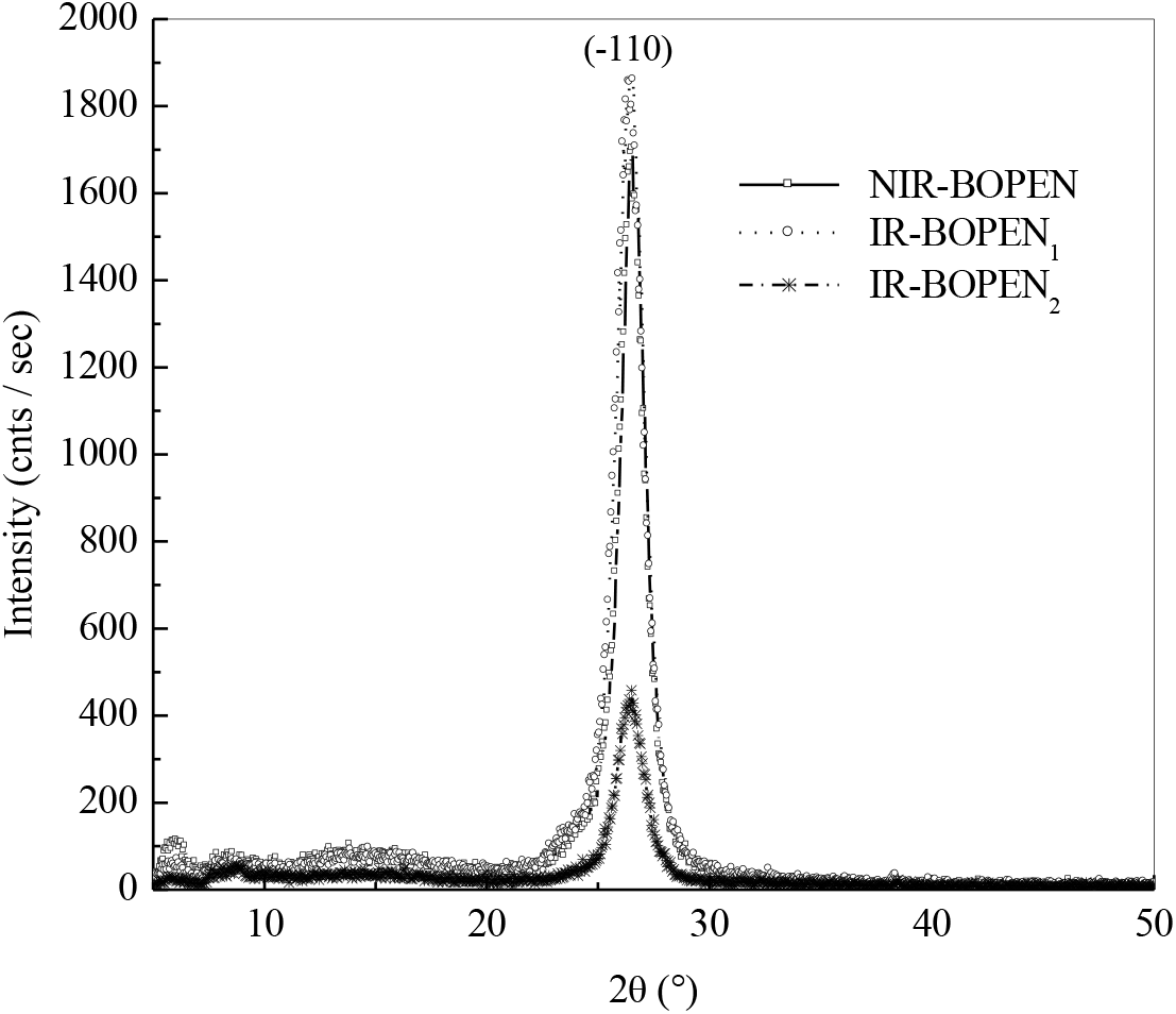
Figure 2.: X-ray spectra of the non-irradiated and irradiated BOPEN films
The crystallization of poly (ethylene-2,6-naphthalate) has been made an object of several investigations. N. Vasanthan and D. R. Salem have showed in their study on the structural and conformational characterization of annealed poly(ethylene 2,6-naphthalate) at 250°C that this polymer crystallizes predominantly in the α-crystal mode[32]. This crystallization type, was highlighted by the apparition of three diffraction peaks at 2θ = 15.60°, 23.30° and 27.00° corresponding, respectively, to (010), (100) and (-110) diffraction planes. These observations have also been found by D. Odaka et al., in their study on crystal growth of heated and cooled amorphous PEN. These authors have signed the existence of three diffraction peaks for 2θ's values equals to 15.5°, 23.3° and 26.9°[33].
The appearance, in Figure 2, of a strong crystallization's peak, at 2θ = 26.56°, indicates the existence of a high planar orientation of the naphthalene ring close to (-110) plane[29]. The intensity of this peak increases in the case of IR-BOPEN1 film contrary to the IR-BOPEN2 where the peak loses about 80% of its intensity. This is an indication that, when the BOPEN film is irradiated by neutrons, where the fluence's components (Ft-n, Ff-n) are equal to (4.03x10¹⁷ n/cm2, 5.05x10¹⁶ n/cm2), the structure of the as-received sample evolutes to a more ordered state. The increase of the crystallinity in polymers exposed to neutrons beam was observed by A. Rivaton et al., in polyethylene oxide (PEO) under the impact of fast neutrons[34] and by Lambri et al., in ethylene- propylene-diene monomer (EPDM) under the effect of neutrons at doses 3-8300Gy[35].
Furthermore, when the pristine film is subjected to the second neutron flux: i.e., fluence's components are (4.61x10¹⁷ n/cm2, 3.86x10¹⁷ n/cm2), the morphology becomes disordered. The structure destruction was also observed by K. Chikaoui et al., in the polyethylene terephthalate (PET) under neutron irradiation[36].
As indicated previously the BOPEN's macromolecule is semi-crystalline. It is composed to an amorphous phase and crystalline phase. The percent of this last can be estimated by calculating of the crystallinity (χ), given in Table 1, and which defined, by Equation (1), as follows:
Where Aa and Ac are the fitted areas of amorphous and crystalline regions, respectively. The values of the crystallinity, shown on the Table 1, are about 56.92% for the IR-BOPEN1 and 25.61% for the IR-BOPEN2.

It must be signaled that the morphology of the crystalline phase is subdivided into three levels of organization.
The first relates to the elementary cell. It can be deduced, from Table 1, that no significant shift of the peak position, (2θ)peak, is observed. This implies that the lattice parameters do not change considerably under the impact of neutrons.
The second is associated with the organization of chains in crystallites (crystalline lamellae). The latter have a dimension less than the length of a macromolecule. This scenario indicates that the same macromolecular chain can belong to several crystalline and amorphous domains and that the macromolecular chain can be folded back on itself in the same crystallite. Generally, semi-crystalline polymers present an alternation of platelets of amorphous phase and crystalline phase, called lamellar structure.
As for the third scale of organization, it refers to the arrangement of the lamellae in a structure called spherulite. Spherulites can reach sizes of about 1mm. They are formed by a helical arrangement of lamellae from a nucleation center. Although spherulites have a crystalline superstructure, these are not themselves completely crystalline.
In bi-stretched polymers, such BOPEN, the stretching causes destruction of the spherulites and leads to a privileged orientation of the crystalline chains and lamellae.
The Scherrer relation, illustrated by Equation (2), gives the relationship between the integral width B of the peak profile on the XRD spectrum and the average size of the crystallites L:
K is the Scherrer constant which depends on the shape of the crystallites. It is dimensionless and its value is close to unity. λ is the wavelength of the X-ray beam. It can be seen clearly, from Table 1, that lamellar structure was transformed into small crystallites during the neutron-BOPEN interaction.
We can see from Figure 3, which summarizes the absorbance bands, for the wave number domains, given in Table 2, that unlike IR- BOPEN2, the response in terms of intensity of the IR-BOPEN1, approaches that recorded in the case of NIR-BOPEN film. Result observed, previously, during the structural characterization by X-ray diffraction.
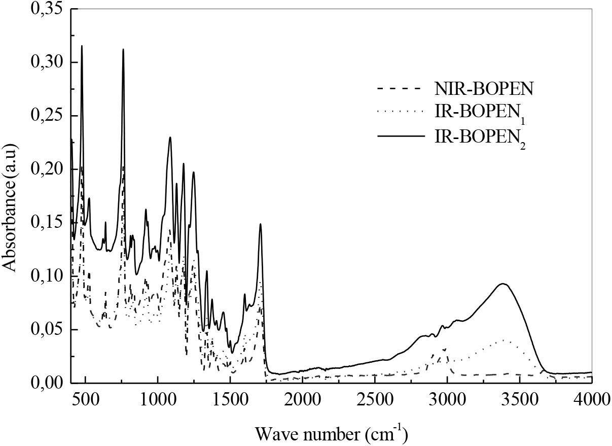
Figure 3.: FTIR spectra in the range 400-4000 cm-1

It must be signaled that the band assignment, given in Table 2, are primarily based on work by Ouchi et al.,[37], F. Kimura et al.,[38] L. Hardy et al.,[39], Y. Zhang et al.,[40] and D. H. Lee et al.,[41].
Moreover, and according to Figure 4, the intensities of the bands, at 406, 476, 762 and 932 cm-1, attributed to the vibrations, outside the naphthalene plane, of the aromatic CHs decrease in the case of the IR-BOPEN1 film. This indicates the presence of a high compactness of crystalline entities in the latter, and consequently, an increase in its rate of crystallinity compared to NIR-BOPEN. A decrease of the degree of crystallinity determined previously in IR-BOPEN2 results in an increase in the intensity of the peaks mentioned above. This conclusion is also highlighted by the evolution of the intensity of the band associated with the symmetrical stretching of the group (CxO), in cis conformation[37], which decreases in the IR- BOPEN1, and increases in IR-BOPEN2, recorded, respectively, at 1087 and 1085 cm-1. We observe a displacement of the carbonyl band, registered in the case of the non-irradiated BOPEN and the IR-BOPEN1 at 1709 cm-1, towards 1711 cm-1 for IR-BOPEN2.
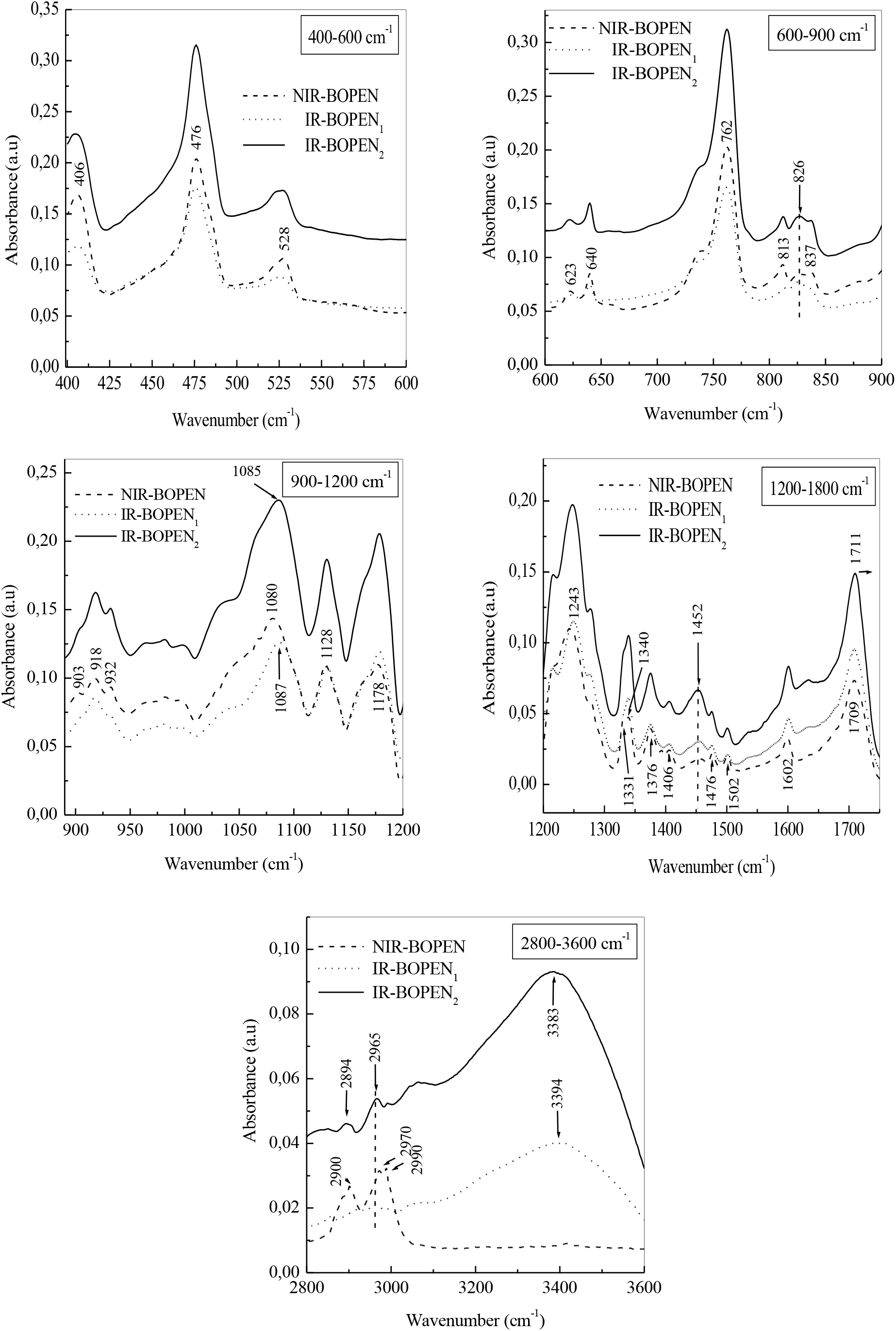
Figure 4.: FTIR spectra of BOPEN films at different wavenumber ranges
This indicates the absence of a coplanarity of the carbonyl groups with the naphthalene groups, and therefore, a decrease in the force constant of the carbonyl bond, caused by the neutron irradiation. This phenomenon involves, once again, the crystallization of IR-BOPEN1 and the amorphization of IR-BOPEN2.
It must be signaled that the absence of coplanarity in a material detracts from the intensification of conjugation effects and the donation of electrons to the carbonyl function by the neighboring conjugated group. This is characterized by a shift of the carbonyl band towards high values of the wavenumber. The narrowing of the recorded carbonyl band width to 1711 cm-1 also characterizes an amorphous morphological state.
The peaks at 918, 1128, 1178 and 1406 cm-1, characteristic of the amorphous phase, are almost of the same intensity in NIR-BOPEN, and IR-BOPEN1 but intensify on the IR- BOPEN2's IRTF / ATR spectrum. The bands at 813, 837 and 1502 cm-1, characteristics of the crystalline phase, decrease slightly, in IR- BOPEN1 and IR-BOPEN2.
Note also that the appearance of absorbance bands at 826 and 1452 cm-1, characteristic of the amorphous phase, in irradiated films and which intensifies in the case of IR-BOPEN2. These bands are attributed, respectively, to a sway of the group (CH2) in trans conformation and to a shear of the same group, in cis conformation. In addition, we notice that the band assigned to the (C×O) stretching and aromatic ring vibration is observed at 1249 cm-1 in IR-BOPEN1 and at 1248 cm-1 in IR-BOPEN2.
The peaks at 2900, 2970 and 2990 cm-1 disappear completely in the irradiated films. In addition, we see the appearance of the band at 2894 cm-1, in the case of IR-BOPEN2, attributed to the symmetrical stretching of the C-O group, in cis conformation, and of the band at 2965 cm-1, in IR-BOPEN1, associated with the stretching of the aromatic C×H bond which intensifies in IR-BOPEN2. Note that these two bands are characteristic of the amorphous state.
The presence of the band associated to the vibration by extension of the hydroxyl (OH) group at 3394 and 3383 cm-1 in IR-BOPEN1 and IR-BOPEN2, respectively, is due to the oxidation of macromolecular chains[37, 42]. We notice that these two bands are not thin, so the group (OH) is more or less linked to hydrogen bond.
Rivaton et al.[34], in their work on the study of structural modifications of polymers under the impact of fast neutrons, have attributed the chain oxidation, to the radicals resulting from bond scissions. It must be noted that in the presence of hydrogen bonds the bond (OH) is more or less weakened, which has the consequence of decreasing the stiffness constant of the bond and the wavenumber of the absorbed radiation.
The effect of neutron irradiation on surface morphology of BOPEN samples can be estimated from the SEM micrographs[43], as shown in Figure 5.
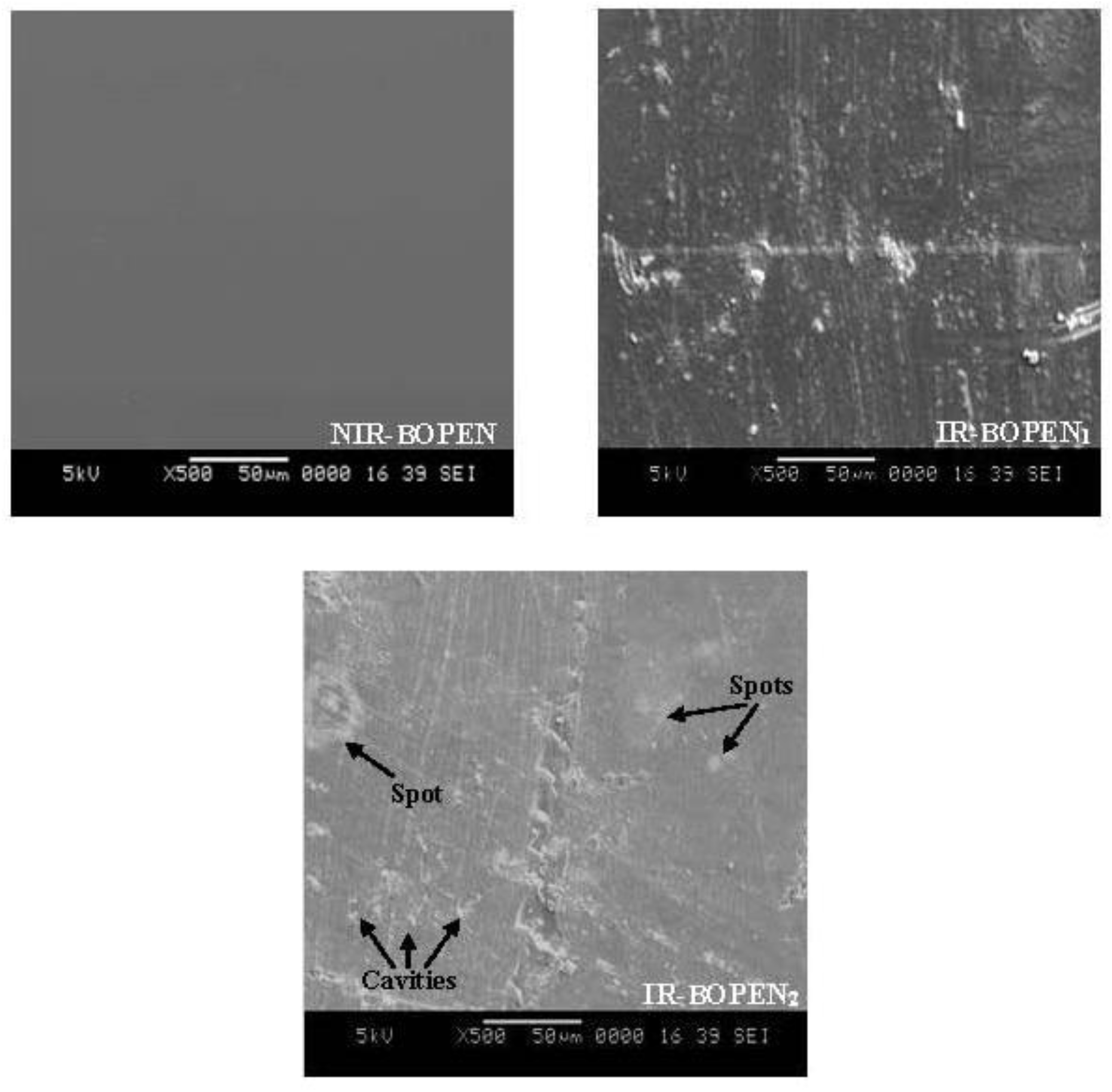
Figure 5.: The SEM micrographs of the surface of BOPEN films with magnification x500
For non-irradiated BOPEN a smooth surface is obtained. Effectively, it is known that the stretching processes conducts to homogenous texture of the surface of bi- stretched polymers[44].
Otherwise, a rough surface is observed, in the case of IR-BOPEN1 film, containing detached particles and scratches. For the IR-BOPEN2 film, a clear material degradation is visible. Effectively, the surface becomes more roughness, in the presence of scratches, cavities, white spots, of different sizes, and a de-bonding[45–47]. It is important to note that the roughness or yet the texturing of the polymer films, induced in our study by neutron radiation, has been the subject of several published works whose goals were, most often, the modification of the properties of wettability[48], adhesion of surfaces[49] and diffuse reflection[50], for biomedical, electrical and photovoltaic industries. The literature reports different methods concerning the texturing of plastic films: the photo-ablation[51], plasma attack[48, 52], and irradiation[43, 53]. The change of the morphology was also observed on different irradiated polymers such as, the polystyrene (PS)[54], the polyvinyl chloride (PVC)[55], the polyvinyl alcohol doped with nitro blue tetrazolium (PVA/NBT)[56] and the polyethylene terephthalate (PET)[57 58]. It must be signaled that the modifications of the surface morphology is an indication that the degree of crystallinity of BOPEN changes, result determined above by XRD analysis. This is due to scissoring and crosslinking effects of macromolecular chains[59–61].
Figure 6 exhibits surface micrographs of the irradiated and non-irradiated films made under polarized light optical microscope.
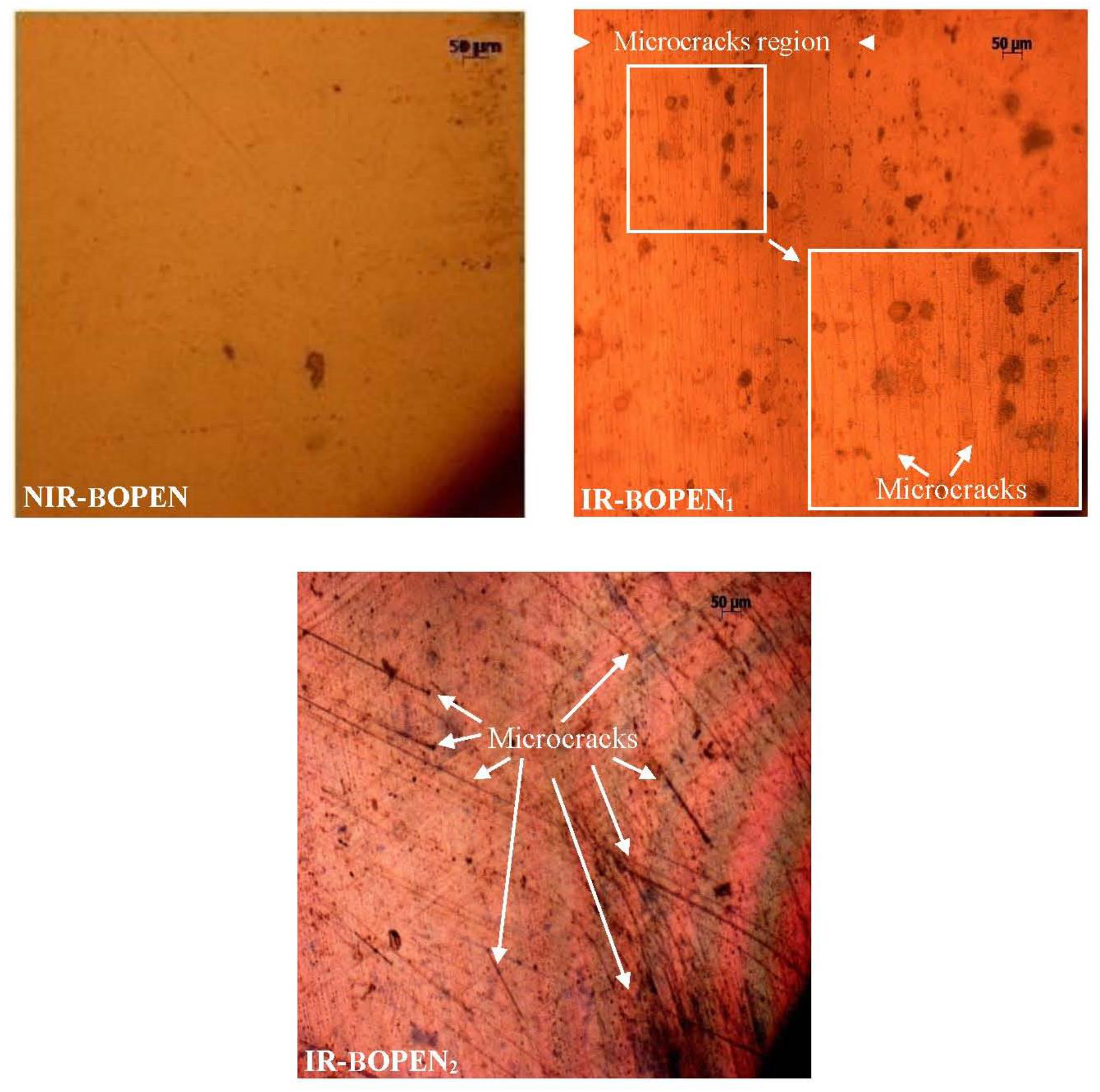
Figure 6.: Optical micrographs of the BOPEN surface with magnification x10
Like the scanning electron microscopy, the polarized light optical microscopy is a technique which provides the information on the surface modifications when it is subject to different constraints such as chemical environment, heat treatment, mechanical impact and irradiation[62–67].
Before the irradiation, the surface of BOPEN sample is regular with no defects. After the irradiation, the BOPEN films show surface irregularities, such as a change in the color and the spots[67–69]. It must be noted that, the PLOM analysis permitted us to identify the scratches observed under scanning electron microscopy. Effectively, the PLOM micrographs show the presence of the microcracks which, in the case of the IR-BOPEN2 film, invade the totality of the surface contrary for the IR-BOPEN1, where the microcracks occupy a limited region, as shows the Figure 6. Awaja et al.[62], in their review on the cracks and microcracks in polymer structures, assigned the formation and the propagation of microcracks the exposure of these last variable environmental conditions such as temperature, moisture, chemicals, radiation and high particles energy.
They also noted that the microcracks constitute the principal cause of the materials failure in reason of the induced structure fragmentation which conduct to the destruction of their physical properties[70]. In addition, the microcracking provide exits offered the possibility of the moisture and the oxygen to reach the polymer matrix. This confirm the oxidation of macromolecular chains in IR- BOPEN films deduced above by FTIR/ATR analysis.
In this study, the ionizing radiation chosen is composed of fast and thermal neutron beams. An X-ray diffraction analysis of the structure of bi-oriented polyethylene naphthalate showed that the degree of the crystallinity and the crystallite size of the BOPEN film varies and depends to the applied neutron fluence. The modification of the BOPEN's was also observed through FTIR analysis. This technique showed, on one hand, a high compactness of crystalline regions in IR-BOPEN1 which disappears in the case of the IR-BOPEN2. On other hand, an oxidation of macromolecular chains were highlighted by the presence of the band associated with the vibration of the hydroxyl (OH) group in irradiated films.
A change of the morphology was also deduced in surface, of the irradiated films, through the analyze of the SEM and PLOM micrographs. These showed that the surface becomes rough. The roughness is a property which is considered as one of the key parameters which permits the identification of the polymer materials quality. For this, an in-depth study of the texturing of PEN films by neutron irradiation is necessary in order to highlight the contribution of this technique in the treatment of polymers surface for industrial use. A lot of surface defects such as the spots, the detached particles, cavities, discoloration and microcracks were also highlighted by these two observation techniques.
References
1. J. L. Leory, J. L. Huet, I. Szabo, C. Le Rigoleur and D. Abramson, Rev. Phys. Appl. 4(1969):251. [Google Scholar]
2. M. Maurette and J. Mory, Rev. Phys. Appl. 3 (1968):209. [Google Scholar]
3. Y. Haruvy, Radiat. Phys. Chem. 35(1990):204. [Google Scholar]
4. J. Garankin, A. Plukis and E. Lagzdina, Energetika. 63(2017):121. [Google Scholar]
5. I. Sen, M. Urffer, D. Penumadu, S. A.Young, L. F. Miller and A. N . Mabe, IEEE Trans. Nucl. Sci. NS 59(2012):1781. [Google Scholar]
6. H. Nakamura, Y. Shirakawa, S. Takahashi and H. Shimizu, Europhys. Lett. 95(2011):22001. [Google Scholar]
7. D. Fluhs, A. Fluhs, M. Ebenau and M. Eichmann, Ocul. Oncol. Pathol. 2(2016):5 [Google Scholar]
8. H. Nakamura, Y. Shirakawa, S. Takahashi, H. Kitamura, T. Yamada, Z. Shidara, T. Yokozuka, P. Nguyen and T. Takahashi, Radiat. Meas. 59(2013):172. [Google Scholar]
9. H. Nakamura, T. Yamada, Y. Shirakawa, H. Kitamura, Z. Shidara, T. Yokozuka, P. Nguyen, M. Kanayama and S. Takahashi, Appl. Radiat. Isot. 80(2013):84. [Google Scholar]
10. Z. Mencik, Chem. Prum. 17(1967):78. [Google Scholar]
11. I. Ishigaki and F. Yoshii, Int. J. Radiat. Appl. Instrum. C. Radiat. Phys. Chem. 39(1992):527. [Google Scholar]
12. A. Biswas, S. Lotha, D. Fink, J. P. Singh, D. K. Avasthi, B. K. Yadav, S. K. Bose, D. T. Khating and A. M. Avasthi, Nucl. Instrum. Methods Phys. Res. B. 159(1999):40. [Google Scholar]
13. B. Mallick, Appl. Phys. A. 119(2015):653. [Google Scholar]
14. H. A. Al-Jabouri, Detection. 3(2015):15. [Google Scholar]
15. A. Drozdziel, M. Turek, K. Pyszniak, S. Prucnal, R. Luchowski, W. Grudzinski, A. Klimek-Turek and J. Partyka, Acta Phys. Pol. A. 132(2017):264. [Google Scholar]
16. S. G. Prasad, A. De and U. De, Int. J. Spectrosc. 2011(2011):1. [Google Scholar]
17. C. Liu, Y. Jin, Z. Zhu, Y. Sun, M. Hou, Z. Wang, Y. Wang, C. Zhang, X. Chen, J. Liu and B. Li, Nucl. Instrum. Methods Phys. Res. B.169(2000):72. [Google Scholar]
18. C. Liu, Z. Zhu, Y. Jin, Y. Sun, M. Hou, Z. Wang, Y. Wang, C. Zhang, X. Chen, J. Liu and B. Li, Nucl. Instrum. Methods Phys. Res. B. 169(2000):78. [Google Scholar]
19. A. V. Rajulu, R. L. Reddy, D. K. Avasthi and K. Asokan, Radiat. Eff. Defects Solids, 152(2000):57. [Google Scholar]
20. M. Negrin, E. Macerata, G. Consolati, L. Di Landro and M. Mariani. Radiat. Eff. Defects Solids. 173(2018):842. [Google Scholar]
21. V. J. Krasnansky, B. G. Achhammer and M. S. Parker. Polym. Eng. Sci. 1(1961):133. [Google Scholar]
22. J. W. Mackersie and M. J. Given, R. A. Fouracre, in “Proceedings of the 2004 IEEE International Conference on Solid Dielectrics”: Piscataway, 2004, p. 387. [Google Scholar]
23. L. G. Molokanova, Y. K. Kochnev, A. N. Nechaev, S. N. Chukova and P. Y. Apel, High. Energy. Chem. 51(2017):182. [Google Scholar]
24. M. Mariani, U. Ravasio, V. Varoli, G. Consolati, A. Faucitano and A. Buttafava, Rdiat. Phys. Chem. 76(2007):1385. [Google Scholar]
25. J. Wetzel, E. Tiras, B. Bilki, Y. Onel and D. Winn, J. Instrum. 11(2016):P08023. [Google Scholar]
26. L. Qi, N. Li, H. Sun, J. Chen and J. Rocks, in “Electrical Insulation Conference”: Seattle, Washington, USA, 2015, p.102. [Google Scholar]
27. K. Devgan, L. Singh and K. S. Samra, Radiat. Phys. Chem. 88(2013):49. [Google Scholar]
28. H. G. Zachman, D. Wiswe, R. Gehrke and C. Riekel, Makromol. Chem. 12(1985):175. [Google Scholar]
29. T. N. Blanton, Powder diffr. 17(2002):125. [Google Scholar]
30. J. Greener, A. H. Tsou and T. N. Blanton, Polym. Eng. Sei. 39(1999):2403. [Google Scholar]
31. M. Cakmak, Y. D. Wang and M. Simhambhatla, Polym. Eng. Sci. 30(1990):721. [Google Scholar]
32. N. Vasanthan and D. R. Salem, Macromolecules. 32(1999):6319. [Google Scholar]
33. D. Odaka, M. Komatsu and Y. Ohki Y, in “IEEE International Conference on Dielectrics”: Montpellier, France, 2016, p. 593. [Google Scholar]
34. A. Rivaton and J. Arnold, Polym. Degrad. Stab. 93(2008):1864. [Google Scholar]
35. O. A. Lambri, L. M. Salvatierra, F. A. Sanchez, C. L. Matteo, P. A. Sorichetti and C. A. Celauro, Nucl. Instrum. Methods Phys. Res. B. 237(2005):550. [Google Scholar]
36. K. Chikaoui, M. Izerrouken, M. Djebara and M. Abdesselam. Radiat. Phys. Chem. 130(2017):431. [Google Scholar]
37. I. Ouchi, M. Hosoi and S. Shimotsuma, J. Appl. Polym. Sci. 21(1977):3445. [Google Scholar]
38. F. Kimura, T. Kimura, A. Sugisaki, A. Komatsu, H. Sata and E. Ito, J. Polym. Sci. B. 35(1997):2741. [Google Scholar]
39. L. Hardy, I. Stevenson, A. M. Voice and I. M. Ward, Polymer. 43(2002):6013. [Google Scholar]
40. Y. Zhang, S. Mukoyama, K. Mori, D. Shen, Y. Ozaki and I. Takahashi, Surf. Sci. 600(2006):1559. [Google Scholar]
41. D. H. Lee, K. H. Park, Y. H. Kim and H. S. Lee, Macromolecules. 40(2007):6277. [Google Scholar]
42. T. Steckenreiter, E. Balanzat, H. Fuess and C. Trautmann, Nucl. Instrum. Methods. Phys. Res. B. 131(1997):159. [Google Scholar]
43. N. L. Mathakari, V. N. Bhoraskar and S. D. Dhole, Radiat. Eff. Defects Solids. 169(2014):779. [Google Scholar]
44. S. Berdous, D. Berdous, N. Amroun-Saidi, D. E. Akretche and M. Saidi, Int. J. Polym. Anal. Charact. 18(2013):358. [Google Scholar]
45. D. Garcia-Garcia, J. E. Crespo-Amorós, F. Parres and M. D. Samper, Polymers. 12(2020):862. [Google Scholar]
46. D. Ahmed, G. El-Hiti, A. Hameed, E. Yousif and A. Ahmed, Molecules. 22(2017):1506. [Google Scholar]
47. G. El-Hiti, M. Alotaibi, A. Ahmed, B. Hamad, D. Ahmed, A. Ahmed and E. Yousif, Molecules. 24 (2019):803. [Google Scholar]
48. Y. L. Hsieh and E. Y. Chen, Ind. Eng. Chem. Res. Dev. 24(1985):246. [Google Scholar]
49. C. Jama, O. Dessaux, P. Goudmand, B. Mutel, L. Gengembre, S. Vallon, J. Grimblot, Surf. Sci. 352-354(1996):490. [Google Scholar]
50. M. Fonrodona, J. Escarre, F. Villar, D. Soler, J. Asensi, J. Bertomeu and J. Andreu, Sol. Energy Mater. Sol. Cells. 89(2005):37. [Google Scholar]
51. J. S. Rossier, P. Bercier, A. Schwarz, S. Loridant and H. H. Girault, Langmuir. 15 (1999):5173. [Google Scholar]
52. N. Inagaki, S. Tasaka and S. Shimada, J. Appl. Polym. Sci. 79(2000):808. [Google Scholar]
53. P. Apel, A. Schulz, Nucl. Instrum. Methods Phys. Res. B. 146(1998):468. [Google Scholar]
54. A. A. Ahmed, D. S. Ahmed, G. A. El-Hiti, M. H. Alotaibi, H. Hashim and E. Youssif, Appl. Petrochem. Res. 9 (2019):169. [Google Scholar]
55. M. H. Alotaibi, G. A. El-Hiti, H. Hashim, S. A. Hameed, D. S. Ahmed and E. Yousif, Heliyon. 4 (2018):e01013. [Google Scholar]
56. S. Alashrah, Y. El-Ghoul and M. A. A. Omer, Polymer. 13(2021):13. [Google Scholar]
57. S. Zhu, M. Shi, M. Tian, L. Qu and G. Chen, J. Text. Inst. 109 (2017):294. [Google Scholar]
58. G. Martínez-Barrera, N. González-Rivas, E. Vigueras-Santiago, A. Martínez-López, J. A. Tello-González and C. Menchaca-Campos, “in Composites from Renewable and Sustainable Materials”, M. Poletto (EdIntech Open: United Kingdom, 2016, Ch. 9, p. 162. [Google Scholar]
59. J. Gao, Z. Ni and Y. Liu, E polym. 16 (2016):1. [Google Scholar]
60. S. Raghu, K. Archana, C. Sharanappa, S. Ganesh and H. Devendrappa, J. Radiat. Res. Appl. Sci. 9 (2016):117. [Google Scholar]
61. S. Raghu, S. Kilarkaje, G. Sanjeev, G. K. Nagaraja and H. Devendrappa, Radiat. Phys. Chem. 98 (2014):124. [Google Scholar]
62. F. Awaja, S. Zhang, M. Tripathi, A. Nikiforov and N. Pugno, Prog. Mater. Sci. 83(2016536. [Google Scholar]
63. D. Maji and S. Das, J. Phys. D. 47(2014):105401. [Google Scholar]
64. P. Du, M. Wu, X. Liu, Z. Zheng, X. Wang, P. Sun, T. Joncheray and Y. Zhang, New J. Chem. 38 (2014):770. [Google Scholar]
65. C. Mondal, A. K. Mukhopadhyay, T. Raghu and V. K. Varma, Mater. Sci. Eng. A, 454-455(2007):673. [Google Scholar]
66. R. Ramani, G. Shariff, M. C. Thimmegowda, P. M. Sathyanarayana, M. B. Ashalatha, A. Balraj and C. Ranganathaiah, J. Mater. Sci. 38(2003):1431. [Google Scholar]
67. A. A. Yaseen, E. T. B. Al-Tikrity, E. Yousif and D. S. Ahmed, B. M. Kariuki, G. A. El-Hiti, Polymers. 13(2021):2982. [Google Scholar]
68. A. G. Hadi, K. Jawad, G. A. El-Hiti, M. H. Alotaibi, A. A. Ahmed, D. S. Ahmed and E. Yousif, Molecules. 24(2019):3557. [Google Scholar]
69. O. G. Mousa, G. A. El Hiti, M. A. Baashen, M. Bufaroosha, A. Ahmed, A. A. Ahmed, and E. Yousif, Polymers. 13(2021):500. [Google Scholar]
70. J. W. C. Pang and I. P. Bond, Compos Sci Technol. 65(2005):1791. [Google Scholar]
Cite This Article
 Copyright © 2022 The Author(s). Published by Tech Science Press.
This work is licensed under a Creative Commons Attribution 4.0 International License , which permits unrestricted use, distribution, and reproduction in any medium, provided the original work is properly cited.


 Submit a Paper
 Propose a Special lssue
 View Full Text
 Download PDF
 Downloads
 Citation Tools