
 Submit a Paper
 Propose a Special lssue
 Open Access
ARTICLE
Experimental Study on Additional Stress Induced by Grouting with Polyurethane-Modified Cementitious Materials under Confined Conditions
1 School of Civil Engineering and Architecture, Zhejiang University of Science and Technology, Hangzhou, 310023, China
2 Zhejiang-Singapore Joint Laboratory for Urban Renewal and Future City, Hangzhou, 310023, China
3 School of Mechanics, Civil Engineering and Architecture, Northwestern Polytechnical University, Xi’an, 710072, China
* Corresponding Authors: Baoping Zou. Email: ; Xu Long. Email:
Journal of Polymer Materials 2025, 42(2), 463-475. https://doi.org/10.32604/jpm.2025.064257
Received 10 February 2025; Accepted 08 May 2025; Issue published 14 July 2025
 View Full Text
 Download PDF
Abstract
The rapid development of urban rail transit has posed increasing construction and operational challenges for metro tunnels, often leading to structural damage. Grouting technology using cement-based materials is widely applied to address issues such as seepage, leakage, and alignment correction in shield tunnels. This study investigates the additional stress induced by grouting in silty soil layers, using cement-based grouts with different water-to-cement ratios and polyurethane-modified cement-based materials. Results show that additional stress decreases with depth and is more influenced by horizontal distance from the grouting point. In staged grouting, the first injection phase contributes about 50% of the peak additional stress. A lower water-to-cement ratio (e.g., 0.6) increases additional stress but reduces grout flowability, while a higher ratio (≥1.0) improves diffusion but increases the risk of grout loss. The polyurethane-modified cement-based material enhances stress transfer performance, increasing peak additional stress by approximately 10%. These findings provide theoretical guidance for optimizing material selection and grouting design in metro tunnel repair within silty soil layers.Keywords
With the development of urban economies and the expansion of city scales, the construction of rail transit has progressed rapidly. As a representative vehicle of rail transit, the metro has been widely adopted in China. However, due to the complexity and concealed nature of underground engineering, metro tunnels often encounter various types of damage during their construction and operation, which can affect their service life. These damages include water seepage, cracks, tunnel lining misalignment, longitudinal settlement, and convergence deformation, among others [1–5]. Among the various tunnel repair methods, Grouting technology is widely recognized as an effective solution for addressing seepage, leakage, and misalignment issues in shield tunnels, offering significant improvements in structural integrity and durability [6–9].
Cement, being the most widely used grouting material, is favored for its high strength and availability [10–13]. As a result, researchers both domestically and internationally have conducted studies on polymer-modified cement-based grouting materials. Wang et al. [14] prepared a polyurethane composite grouting material and used field tests to identify that a hybrid interpenetrating gel network structure was crucial to enhancing the material’s impermeability. In recent studies, the influence of polymer–curing agent ratios on the rheological behavior and mechanical strength of epoxy-modified cement grouts has been systematically examined, showing that appropriate polymer content can significantly enhance both strength and workability [15]. Additionally, Wang et al. [16] compared the mechanical performance of permeable polymer-reinforced silty-fine sand with that of traditional grouting materials, highlighting the advantages of polymer grouts in improving strength and reducing brittleness in silty soil environments. Yu et al. [17] investigated the effects of polyether polyols on the viscosity, compressive strength, and oxygen index of silicate-modified polyurethane materials. Pan et al. [18] studied the deformation and failure mechanisms of polyurethane foam grouting materials and summarized the impact of specimen size and strain rate on their compressive performance. Cai et al. [19] discussed the influence of the selection and ratio of waterborne polyurethane composites on their physicochemical properties. Hao et al. [20] identified the diffusion pattern of polyurethane grouting materials in water-containing cracks through indoor grouting experiments. Additionally, Wang et al. [21] improved the mechanical properties of low-permeability silty soils by incorporating polyurethane into grouting materials, showing that polymers have potential applications in various fields, including seepage prevention, embankment reinforcement, subgrade stabilization, and foundation strengthening.
Existing theoretical studies on tunnel grouting repair mainly focus on the development of specialized equipment and numerical models. For instance, Ma et al. [22] independently developed a lateral grouting device and studied various grouting methods such as single-hole and double-hole lateral grouting, investigating the stress state and deformation repair mechanisms of tunnels. Zheng et al. [23] applied a small-strain model for numerical simulations to study the disturbance mechanism of compensation grouting on soil. Liang et al. [24] based on the rheological characteristics of grouting materials and the theory of viscous fluid dynamics, used finite element analysis and experimental studies to model the diffusion pattern of polymer grouts. Ying et al. [25] established a grouting diffusion model considering the heterogeneous pore spaces in the strata to study grout diffusion patterns. Huang et al. [26] performed unit tests with cement slurry of different water contents in sandy soils, studying the distribution of additional soil pressures and the grout diffusion pattern, in order to identify the most suitable water content and grouting methods. Similar to the modification of cement-based materials, a study by Manda et al. [27] on the confinement of Tin Slag Polymer Concrete (TSPC) with fiber-reinforced polymers (FRPs) found that Aramid Fiber Reinforced Polymer (AFRP) significantly improved the material’s strength and toughness, particularly in fracture energy and yield stress, outperforming Basalt Fiber Reinforced Polymer (BFRP). This aligns with our research on polyurethane-modified cement-based materials used for tunnel grouting, suggesting that polymer modification can effectively enhance the performance of cementitious materials.
In summary, existing research primarily focuses on the properties of grouting materials, while the theory of grouting repair remains incomplete, with limited attention given to the additional stresses induced in the surrounding soil layers. Under constrained conditions, studies on the diffusion mechanism and additional stresses of polymer-modified cement-based grouting materials in silty soils are particularly scarce. To address this gap, this study innovatively employs a confining pressure loading device to simulate constrained conditions and conducts unit tests using cement-based materials with different water-to-cement (W/C) ratios and polyurethane-modified cement-based materials. The impact of different W/C ratios and polymer materials on the distribution of additional stresses induced by grouting in silty soil layers is systematically analyzed.
2.1 Grouting Material Description
In this experiment, conventional Portland cement is used as the conventional cement-based grouting material, and water-based polyurethane is used as the polymer additive.
(1) Cement
The experimental grouting material consisted of PI 42.5-Grade Portland cement, selected for its standardized mechanical properties and widespread applicability in geotechnical engineering. Its chemical composition and basic performance parameters are shown in Tables 1 and 2, respectively.


(2) Water-Based Polyurethane (WPU)
The basic properties of the water-based polyurethane (WPU) used in this experiment are shown in Table 3. The WPU material is in an oily form at room temperature, with a color ranging from light yellow to light brown.

(3) Soil Used in the Experiment
The soil used in the experiment was selected from a silty clay layer of a project in the Guangzhou area. In the experiment, the strata were simplified to a single layer. The soil parameters are shown in Table 4.

Based on the results of bending and compressive strength tests on the polyurethane-modified grouting materials (as shown in Fig. 1), a 6% water-based polyurethane content is selected for the polyurethane-modified cement-based grouting material. Additionally, tests on the fluidity performance of the grout were conducted. The measured spread diameter was 140.5 mm without the addition of polyurethane, and 144 mm when 6% polyurethane was added, indicating that the addition had minimal effect on the fluidity of the grout.

Figure 1: Mechanical properties of grouting materials after 28 days of curing
(1) Confining Pressure Loading Box
The equipment mainly consists of a structural frame, loading plates, hydraulic pipelines, servo oil sources, and linear slide rails. The internal loading system includes a front loading plate, a bottom loading plate, and loading plates on the other four sides, forming a model box with clear dimensions of 0.5 m × 0.5 m × 0.5 m. The thickness of each loading plate is 0.05 m, and the system has high overall stiffness, which allows it to withstand the simulated real ground stress and the pressure transmitted during the grouting process. During loading, the system exhibits no deformation. This ensures the accuracy of the simulated test process, as shown in Fig. 2. This loading system can continuously apply loading force, and once the applied load reaches the set value, it can maintain a constant pressure, thus simulating the real ground stress environment at various tunnel burial depths to the greatest extent.

Figure 2: Confining pressure loading system
(2) Monitoring System
The main monitoring element used in the experiment is the soil pressure cell. Data is collected through a DH3816N static strain gauge acquisition instrument connected to a computer to monitor the changes in additional stress applied to the soil during the entire grouting process. To monitor stress distribution, 20 soil pressure cells were strategically placed around the test area to ensure comprehensive data acquisition during grouting, numbered 1# to 20# as shown in Fig. 3. Based on the burial depths, the depths corresponding to cells 4#, 9#, 14#, and 19# are defined as L1, the depths corresponding to cells 1#–3#, 6#–8#, 11#–13#, and 16#-18# are defined as L2, and the depths corresponding to cells 5#, 10#, 15#, and 20# are defined as L3.
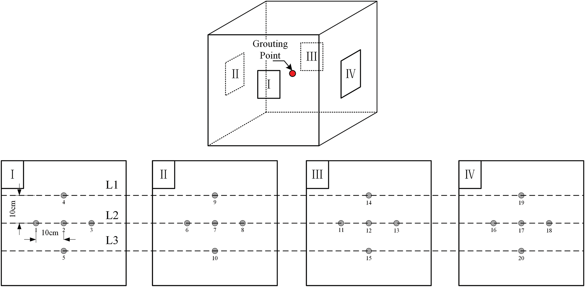
Figure 3: Layout of soil pressure cells for monitoring stress distribution
(3) Grouting System
Considering both the accuracy and operability of the experiment, a mature flow-controlled grouting device was used in this study. After technical adjustments in collaboration with the manufacturer, the system employs a tungsten steel pump, which enhances its resistance to the grouting materials. As shown in Fig. 3, the grouting point is located at the center of the soil box.
The specific experimental procedure is shown in Fig. 4. The side baffle plate of the soil box is installed, and the soil is filled into the soil box in layers, with each layer being compacted. After reaching the specified position, the grouting pipe is buried, and the soil is further filled to the set height. The baffle plate is then removed, and the soil is pushed into the loading system.

Figure 4: Schematic representation of grouting test procedure
After the soil filling is completed, confining pressure loading is applied. The confining pressure is applied to the top-bottom and front-back faces, with a magnitude of 7.5 kPa, simulating the soil pressure at a depth of 10 m underground. Fig. 5 shows the confining pressure loading curve.

Figure 5: Loading curve of the confining pressure
To measure the changes in additional stress during grouting, the principle of “small amounts, multiple injections” [26] should be followed. After the confining pressure loading is completed, 1.5 L of cement grout is injected into the soil in three phases, with 0.5 L injected in each phase and a 200-s interval between each injection.
A total of six different working conditions were conducted in this study. Five groups of Portland cement grouting materials (Working Conditions 1–5) with varying W/C ratios (that is, 0.4, 0.6, 0.8, 1.0, and 1.2) were prepared to establish the baseline relationship between W/C ratio and stress distribution. Additionally, a single group of polyurethane-modified cement-based grout (Working Condition 6*) was tested at a W/C ratio of 0.6 with 6% polyurethane content to evaluate the effects of polymer modification on stress distribution under similar conditions. By comparing a single set of polyurethane-modified cement-based grout with varying conventional cement-based grout compositions, we provide preliminary insights into the potential benefits of polymer modification. This preliminary study used single measurements for each condition; future work will include replicates to assess variability and enhance the robustness of the findings. The selection of W/C ratios was based on the findings by Yang [28], that investigated the effect of W/C ratio on the performance of cement slurries. The specific W/C ratios used are listed in Table 5.

Experimental observations revealed that when the W/C ratio was below 0.4, pipe blockage frequently occurred during the grouting process; whereas when the ratio was greater than or equal to 1.0, slurry loss was prone to occur during the second phase of grouting. Therefore, a W/C ratio of 0.6 was adopted for analyzing the stress distribution pattern and polymer effects to obtain comprehensive results. When examining the effect of W/C ratios, the analysis focused on the additional stresses generated during the first phase of grouting for different ratios. The detailed analysis flowchart is presented in Fig. 6.

Figure 6: Experimental group-based discussion flowchart
3.1 Stress Distribution Pattern
Fig. 7 shows the variation curves of additional stress at different depths during the grouting process when the W/C ratio is 0.6. The solid line represents polymer-modified cement grout, while the dashed line represents ordinary Portland cement grout. After observing the variation over grouting time, it can be seen that the additional stress increases significantly during the first phase of grouting, accounting for approximately 50% of the maximum additional stress. The increases in additional stress during the subsequent two grouting phases are both smaller than that of the first phase, accounting for approximately 30% and 20% of the maximum value, respectively. At the beginning of each grouting phase, the additional stress increases rapidly in an approximately linear fashion, and upon stopping the grouting, the additional stress slightly decreases and then stabilizes. After the third grouting phase, due to grout running, a certain part of the grout is lost, resulting in the additional stress dropping to the stabilized value observed after the second phase. In terms of depth, the maximum additional stress occurs in the middle layer, with the upper layer being about 70% and the lower layer about 40% of that in the middle layer. This is considered to be influenced by the proximity to the grouting point, leading to the preliminary assumption that the closer the soil is to the grouting point, the greater the additional stress induced by the grouting.

Figure 7: Additional stress curves of grouting process at different depths (W/C = 0.6)
Fig. 8 presents the variation curves of horizontal additional stress on surfaces I and III. The solid lines represent polymer-modified cement grout, while the dashed lines represent ordinary Portland cement grout. From the curves, it can be observed that the average additional stress at cells 2# and 12#, which are closer to the grouting point, is approximately twice that at cells 1#, 11#, 3#, and 13#, which are farther from the grouting point. Based on the variation patterns of the curves in both the depth and horizontal directions, it can be concluded that the closer the soil is to the grouting point, the greater the additional stress induced by the grouting. Combining Figs. 7 and 8, it is evident that the incorporation of polyurethane enhances the transmission of additional stress.

Figure 8: The horizontal additional stress curves of I and III surfaces (W/C = 0.6)
3.2 Effect of W/C Ratio and Polymer
This study conducted unit tests under six different working conditions. When the W/C ratio was less than 1.0, the grout loss phenomenon occurred during the third phase of grouting, while for W/C ratios greater than or equal to 1.0, the grout loss phenomenon occurs during the second phase of grouting. These findings are consistent with the results reported by Huang et al. [29], confirming that the W/C ratio significantly influences the diffusion rate of cement-based grout. A higher W/C ratio facilitates rapid grout diffusion due to enhanced fluidity. In silty soil layers, the grout loss phenomenon is more likely to occur in such conditions.
Fig. 9 shows the change in additional stress in the L1 soil layer after the first phase of grouting under different working conditions. When the W/C ratio is 0.4, the peak additional stress caused by grouting in the upper layer is the highest, with a maximum value of 14 kPa. The peak additional stress for W/C ratios between 0.6 and 1.0 does not vary significantly. From the trend in the figure, it can be observed that as the W/C ratio increases, both the peak additional stress and the final stabilized value in the upper layer decrease.

Figure 9: Variation of additional stress in the L1 soil layer after the first phase of grouting under different working conditions
Fig. 10 shows the variation of additional stress in the L2 soil layer after the first phase of grouting under different working conditions. Compared to Fig. 9, the overall trend is similar, with the additional stress caused by grouting being negatively correlated with the W/C ratio. However, from Fig. 10, it can be observed that when the W/C ratio is between 0.8 and 1.2, the peak additional stress caused by grouting is similar, while the final stabilized value is negatively correlated with the W/C ratio. This indicates that, because the L2 soil layer is closer to the grouting point, the effect of the W/C ratio on the peak additional stress is weakened.

Figure 10: Variation of additional stress in the L2 soil layer after the first phase of grouting under different working conditions
Huang [26] suggested that slurry with a low water content is more likely to cause soil particles to densify, resulting in higher stresses. From Figs. 9 and 10, it can be seen that the additional stress after grouting stabilizes decreases with the increase in W/C ratio, while the peak additional stress during the grouting process is more significantly influenced by the distance from the grouting point.
The peak additional soil pressure induced by polyurethane-modified cement-based grouting materials during grouting is approximately 10% higher compared to the baseline grout with the same W/C ratio. The final stable additional soil pressure is slightly higher than that of ordinary cement-based grouting materials. This suggests that polymer modification not only enhances grout compaction and stress transmission but also offers potential for improving long-term stability in tunnel repair applications, likely due to improved rheological properties and interfacial bonding. Due to resource and time constraints, this study includes a single set of polyurethane-modified grout tests. However, the results provide a foundation for future studies investigating a broader range of polymer contents and grouting conditions.
The results show that the smaller the W/C ratio, the greater the additional stress generated by the grout. However, during the experiment, it was observed that a W/C ratio of 0.4 caused blockage in the grouting pipe due to poor flowability.
This study investigated the additional stresses induced by grouting in silty soil layers, focusing on the influence of depth, distance from the grouting point, W/C ratio, and polyurethane modification. The findings provide valuable insights into the stress distribution characteristics and the performance of both conventional and polymer-modified grouts under confined conditions. The achieved conclusions are summarized as follows:
(1) According to the distribution pattern of additional stress induced by grouting in silty soil layers at different depths: The initial grouting phase produces the highest additional stress, accounting for approximately 50% of the total, while the second and third phases account for around 30% and 20%, respectively. As depth increases, the additional stress induced by grouting gradually decreases. The closer the location is to the grouting point, the greater the induced additional stress, and the influence of horizontal distance from the grouting point is more significant than that of depth.
(2) Experimental results indicate that the W/C ratio has a significant effect on the additional stress induced by grouting. As the W/C ratio increases, the fluidity of the grout improves, leading to a faster diffusion rate and consequently lower additional stress. However, when the W/C ratio is greater than or equal to 1, grout loss is more likely to occur.
(3) The selection of an appropriate water-to-cement (W/C) ratio for grouting should balance additional stress performance and grout flowability. A ratio that is too low reduces injectability and may cause pipe blockages, while a high ratio risks grout loss. Based on the results, a W/C ratio of 0.6—especially when combined with polyurethane modification—offers a favorable compromise in silty soils. This provides practical guidance for selecting grouting materials in tunnel reinforcement applications.
(4) Polyurethane-modified cement-based grouting materials can significantly enhance the additional stress induced by grouting, particularly reflected in an approximate 10% increase in peak additional stress. Additionally, it slightly enhances the final stabilized value of the induced additional stress. This behavior suggests that the incorporation of polyurethane contributes to higher stress concentrations near the grouting point, which could potentially influence the long-term stability of tunnel structures.
The interaction between polyurethane and the surrounding materials may involve complex microstructural changes. To gain deeper insights into the internal structure and stress transfer characteristics of the composite material, future studies could employ advanced techniques such as X-ray diffraction (XRD) and computed tomography (CT). It should be noted that this study only examined a single polyurethane content, which is a limitation. Future work is needed to investigate a wider range of polymer dosages and their interactions with various water-to-cement ratios, as well as to assess the performance of polymer-modified grouts in different soil types. Such efforts would help establish a more comprehensive understanding of material behavior and support the development of optimized grouting strategies for complex geotechnical conditions.
Acknowledgement: The authors extend gratitude to all individuals who contributed to the completion of this study.
Funding Statement: This work was supported by the National Natural Science Foundation of China (No. 42477185), Natural Science Foundation of Zhejiang Province (LQ24A020015), Research Achievement Award Cultivation Project of Zhejiang University of Science and Technology (2023JLYB001), the Postgraduate Course Construction Project of Zhejiang University of Science and Technology (2024yjskj05).
Author Contributions: Research conception and design: Qizhi Chen, Baoping Zou, Xu Long; experiments: Wensheng Cheng; results and analysis: Bowen Kong, Yansheng Deng; manuscript preparation: Qizhi Chen, Wensheng Cheng, Xu Long. All authors reviewed the results and approved the final version of the manuscript.
Availability of Data and Materials: The datasets generated and/or analyzed during the current study are available from the corresponding author on reasonable request.
Ethics Approval: Not applicable.
Conflicts of Interest: The authors declare no conflicts of interest to report regarding the present study.
References
1. Ye F, Qin N, Liang X, Ouyang A, Qin Z, Su E. Analyses of the defects in highway tunnels in China. Tunn Undergr Space Technol. 2021;107(8):103658. doi:10.1016/j.tust.2020.103658. [Google Scholar] [CrossRef]
2. Jiang Y, Wang L, Zhang B, Dai X, Ye J, Sun B, et al. Tunnel lining detection and retrofitting. Autom Constr. 2023;152(11):104881. doi:10.1016/j.autcon.2023.104881. [Google Scholar] [CrossRef]
3. Han W, Jiang Y, Wang G, Liu C, Koga D, Luan H. Review of health inspection and reinforcement design for typical tunnel quality defects of voids and insufficient lining thickness. Tunn Undergr Space Technol. 2023;137(16):105110. doi:10.1016/j.tust.2023.105110. [Google Scholar] [CrossRef]
4. Zou B, Chen Y, Bao Y, Liu Z, Hu B, Ma J, et al. Impact of tunneling parameters on disc cutter wear during rock breaking in transient conditions. Wear. 2025;560:205620. doi:10.1016/j.wear.2024.205620. [Google Scholar] [CrossRef]
5. Zou B, Yin J, Liu Z, Long X. Transient rock breaking characteristics by successive impact of shield disc cutters under confining pressure conditions. Tunn Undergr Space Technol. 2024;150:105861. doi:10.1016/j.tust.2024.105861. [Google Scholar] [CrossRef]
6. Liu C, Zhang D, Zhang S, Fang Q, Sun Z. Long-term mechanical analysis of tunnel structures in rheological rock considering the degradation of primary lining. Undergr Space. 2023;10(6):217–32. doi:10.1016/j.undsp.2022.10.005. [Google Scholar] [CrossRef]
7. Liu YK, Deng E, Yang WC, Ni YQ, Zhou Z, Zhang JJ. Aerodynamic intensification effect and dynamic response of cracks on high-speed railway tunnel linings. Tunn Undergr Space Technol. 2023;140:105308. doi:10.1016/j.tust.2023.105308. [Google Scholar] [CrossRef]
8. Zou B, Pei C, Chen Q, Deng Y, Chen Y, Long X, et al. Progress on multi-field coupling simulation methods in deep strata rock breaking analysis. Comput Model Eng Sci. 2025;142(3):2457. doi:10.32604/cmes.2025.061429. [Google Scholar] [CrossRef]
9. He BG, Liu ER, Zhang ZQ, Zhang Y. Failure modes of highway tunnel with voids behind the lining roof. Tunn Undergr Space Technol. 2021;117:104147. doi:10.1016/j.tust.2021.104147. [Google Scholar] [CrossRef]
10. He BG, Liu ER, Zhang ZQ, Zhang Y. Research on workability, mechanics, and durability of cementitious grout: a critical review. Constr Build Mater. 2024;449(3):138374. doi:10.1016/j.conbuildmat.2024.138374. [Google Scholar] [CrossRef]
11. Zou B, Yin J, Cao C. Mechanical performance analysis of rubber elastic polymer-polyurethane reinforced cement-based composite grouting materials. J Polym Mater. 2025;42(1):225. doi:10.32604/jpm.2025.062081. [Google Scholar] [CrossRef]
12. Conde Silva J, Serra C. Injection of discontinuities in concrete dams with cement-based grouts. J Struct Integr Maint. 2022;7(4):252–64. doi:10.1080/24705314.2022.2088070. [Google Scholar] [CrossRef]
13. da Rocha Gomes S, Ferrara L, Sánchez L, Moreno MS. A comprehensive review of cementitious grouts: composition, properties, requirements and advanced performance. Constr Build Mater. 2023;375:130991. doi:10.1016/j.conbuildmat.2023.130991. [Google Scholar] [CrossRef]
14. Wang J, Gao S, Zhang C, Deng Y, Zhang P. Preparation and performance of water-active polyurethane grouting material in engineering: a review. Polymers. 2022;14(23):5099. doi:10.3390/polym14235099. [Google Scholar] [PubMed] [CrossRef]
15. Wang Y, Wu J. Effects of polymer—curing agent ratio on rheological, mechanical properties and chemical characterization of epoxy-modified cement composite grouting materials. Polymers. 2024;16(18):2665. doi:10.3390/polym16182665. [Google Scholar] [PubMed] [CrossRef]
16. Wang Y, Zhang L, Liu M, Yu X. Comparative study on the mechanical properties of solidified silty-fine sand reinforced by permeable polymer and traditional grouting materials. Constr Build Mater. 2024;419(1):135485. doi:10.1016/j.conbuildmat.2024.135485. [Google Scholar] [CrossRef]
17. Yu X, Wang Y, Sun G. Comparative analysis of mechanical properties and fracture characteristics between sodium silicate modified polyurethane and polyurethane materials. Constr Build Mater. 2024;444(8):137917. doi:10.1016/j.conbuildmat.2024.137917. [Google Scholar] [CrossRef]
18. Pan W, Zhang C, Wang C, Fang H, Wang F, Qin Z, et al. Compressive fatigue resistance related microscopic mechanisms in foamed polyurethane grouting materials for roadbed rehabilitation. Int J Fatigue. 2023;171(7):107593. doi:10.1016/j.ijfatigue.2023.107593. [Google Scholar] [CrossRef]
19. Cai J, Murugadoss V, Jiang J, Gao X, Lin Z, Huang M, et al. Waterborne polyurethane and its nanocomposites: a mini-review for anti-corrosion coating, flame retardancy, and biomedical applications. Adv Compos Hybrid Mater. 2022;5(2):641–50. doi:10.1007/s42114-022-00473-8. [Google Scholar] [CrossRef]
20. Hao M, Li X, Zhong Y, Zhang B, Wang F. Experimental study of polyurethane grout diffusion in a water-bearing fracture. J Mater Civ Eng. 2021;33(3):04020485. doi:10.1061/(ASCE)MT.1943-5533.0003612. [Google Scholar] [CrossRef]
21. Wang C, Diao Y, Guo C, Wu H, Guan H, Qin L, et al. Experimental study on the mechanical behaviour of silty soil stabilized with polyurethane. Constr Build Mater. 2024;416:135251. doi:10.1016/j.conbuildmat.2024.135251. [Google Scholar] [CrossRef]
22. Ma M, Yang X, Zhou J, Li L, Tian J. Model tests and numerical simulations of deformation repair effect for operating shield tunnels under horizontal lateral grouting. Transp Geotech. 2024;47(3):101277. doi:10.1016/j.trgeo.2024.101277. [Google Scholar] [CrossRef]
23. Zheng G, Pan J, Cheng XS, Bai RB, Du YM, Diao Y. Passive control and active grouting control of horizontal deformation of tunnels induced neighboring excavation. J Geotech Eng. 2019;41(07):1181–90. doi:10.11779/CJGE201907001. [Google Scholar] [CrossRef]
24. Liang J, Du X, Fang H, Du M, Shi M, Gao X, et al. Numerical and experimental study of diffusion law of foamed polymer grout in fracture considering viscosity variation of slurry. Tunn Undergr Space Technol. 2022;128(8):104674. doi:10.1016/j.tust.2022.104674. [Google Scholar] [CrossRef]
25. Ying K, Ye F, Li Y, Liang X, Su E, Han X. Backfill grouting diffusion law of shield tunnel considering porous media with nonuniform porosity. Tunn Undergr Space Technol. 2022;127:104607. doi:10.1016/j.tust.2022.104607. [Google Scholar] [CrossRef]
26. Huang D, Liu J, Xu C, Luo Z. Experimental study on the influence of slurry diffusion mode on the additional earth pressure of formation. Huazhong Univ Sci Technol. 2023;52(10):20–6. doi:10.13245/j.hust.240297. [Google Scholar] [CrossRef]
27. Manda MS, Rejab MR, Hassan SA, Wahit MU, Binoj JS, Mansingh BB, et al. Tin slag polymer concrete strengthening by basalt aramid fiber reinforced polymer confinement. J Polym Mater. 2022;39(3–4):241–53. doi:10.32381/JPM.2022.39.3-4.5. [Google Scholar] [CrossRef]
28. Yang Y. Study on the diffusion law of grouting slurry and its lifting effect on shield tunnel [master’s thesis]. Shenzhen, China: Shenzhen University; 2019. [Google Scholar]
29. Huang D, Luo Z, Luo W, Zhu B, Liu J, Zhao J. Unit test study on formation and influence factors of additional earth pressure during formation grouting. Chin J Rock Mech Eng. 2024;43(S1):3520–9. doi:10.13722/j.cnki.jrme.2023.0082. [Google Scholar] [CrossRef]
Cite This Article
 Copyright © 2025 The Author(s). Published by Tech Science Press.
This work is licensed under a Creative Commons Attribution 4.0 International License , which permits unrestricted use, distribution, and reproduction in any medium, provided the original work is properly cited.
 Downloads
 Citation Tools