
 Submit a Paper
 Propose a Special lssue
 Open Access
ARTICLE
Bi-Crown-Ether Modified Bi-Piperidinium Anion Exchange Membranes for Fuel Cell Applications
1 State Key Laboratory of Fine Chemicals, Dalian University of Technology, Dalian, 116024, China
2 School of Chemical Engineering, Ocean and Life Sciences, Dalian University of Technology, Panjin, 124221, China
3 Institute of Chemical and Environmental Engineering, Khwaja Fareed University of Engineering and Information Technology (KFUEIT), Abu Dhabi Rd, Rahim Yar Khan, 64200, Pakistan
* Corresponding Authors: Naeem Akhtar Qaisrani. Email: ; Fengxiang Zhang. Email:
Journal of Polymer Materials 2025, 42(4), 893-908. https://doi.org/10.32604/jpm.2025.071240
Received 03 August 2025; Accepted 30 October 2025; Issue published 26 December 2025
 View Full Text
 Download PDF
Abstract
Anion exchange membrane (AEM) fuel cells require membranes with a balance of high conductivity and durability. In this work, a novel bi-crown-ether modified piperidine structure was designed and synthesized, which was then introduced into the side chain of poly(arylene piperidinium), making a unique bi-crown-ether modified bi-piperidinium side chain grafted polymer for AEM fabrication. The double crown ether units enhanced cation–water interactions and promoted microphase separation, thereby forming efficient hydroxide ion transport channels. The resulting membrane exhibited high water uptake, well-defined ion clusters, and a hydroxide conductivity of 123 mS cm−1 at 80°C with an ion exchange capacity (IEC) of 1.56 mmol g−1. After alkaline treatment in 1 M NaOH at 80°C for 960 h, the membrane retained ~85% of its initial conductivity, demonstrating excellent chemical stability. In H2/O2 fuel cell tests at 60°C, the membrane achieved a peak power density of 558 mW cm−2 at 1040 mA cm−2. These findings highlight the potential of bi-crown-ether modified piperidinium side chain grafting as an effective strategy to enhance ion conduction properties of AEMs for fuel cell applications.Keywords
Fuel cells are increasingly gaining popularity as a clean source of energy, particularly with the growing demand for sustainable energy. Among different types of fuel cells, alkaline anion exchange membrane fuel cells (AAEMFCs) have gained consideration owing to their compatibility with low-cost oxygen reduction catalysts. However, their performance is still limited by the properties of the membrane, which needs to have high ionic conductivity, low electron conductivity, and outstanding alkaline and mechanical stability [1,2]. In recent years, there has been an increasing focus on the development of improved anion exchange membranes (AEMs) aimed at boosting the efficiency of AAEMFCs. [3–5]. However, AEMs suffer from several limitations, including low hydroxide conductivity, poor chemical and mechanical stability, and water management issues. To overcome these limitations, researchers have focused on modifying the structure of the polymer, such as introducing hydrophilic groups, to enhance the membrane’s properties [6–8].
Various materials have been explored to develop AEMs, including PPO [9,10], PEEK [11], PAEK [12] and PSF [6], because of their ease of structure modification and good membrane-forming ability. Nonetheless, the chain scission reaction of these polymers’ backbone is likely to occur in an alkaline medium as a result of hydroxide ion attack [8,13]. Recently, there has been a focus on developing chemically and thermally stable arylene-based polymers for use in AEMs. These polymers are synthesized through acid-catalyzed polycondensation and have shown good alkaline stability. For instance, Chen et al. [14] testified that AEM poly(fluorenyl aryl piperidinium) could endure 80°C treatment in 1 molar NaOH solution for 2000 h. To enhance alkaline stability, introducing long side-chains hanging the ion conducting clusters and optimizing the hydration level of cationic groups have been proposed. Furthermore, studies have demonstrated that the alkali confrontation of these materials is influenced by the level of hydration surrounding their cationic groups [15,16]. The more heavily hydrated cations are believed to degrade at a slower rate in alkaline environments as a result of steric hindrance caused by the solvent cage effect [17–19].
Ensuring that AEM-based devices deliver a high power output requires not only stability but also the attainment of high hydroxide conductivity. Typically, the superior conductivity of AEMs is a result of their greater ion exchange capacity, which can be increased by attaching more cations onto the polymer. However, having too many cationic groups can result in excessive water uptake and reduced stability of the AEMs [20]. Creating rapid ion transport pathways through the construction of a suitable microphase-separated structure in AEMs has been identified as a more effective method for achieving high conductivity at a suitable ion exchange capacity level [21,22].
According to reported literature, the use of block copolymers [23], densely functionalized polymers [24] and long side chain grafted polymers [25], has been found to be beneficial in promoting microphase separation. Additionally, interactions between molecules, including electrostatic attractions and hydrogen bonding, have been employed to encourage the accumulation of cationic groups, resulting in the creation of uninterrupted ion channels [26,27]. Moreover, it has been demonstrated that incorporating a bulky 3D structure into AEMs is an easier technique to increase their conductivity [28]. Kim et al. [29] have observed that the inclusion of segments (triptycene) in the polymer backbone can promote the creation of clearly separated microphase morphology by increasing the free volume of the membranes. The nanochannels within AEMs that contain quaternary ammonium (QA) [30], guanidinium [31], phosphonium [32], imidazolium [30], and pyrrolidinium [33] groups are believed to be essential for transporting hydroxyl ions (OH−). The easy preparation and low cost of QA make it the most commonly used anion exchange group, but it is susceptible to decomposition in a strong basic environment through nucleophilic substitution or Hofmann elimination. Several strategies have been implemented to enhance the chemical durability of AEMs, including altering the position of cationic groups [34] and crosslinking the structure. However, it is still challenging to reconcile the trade-off between alkaline stability and conductivity. Therefore, developing design strategies that simultaneously enhance ionic conductivity and chemical durability remains a critical challenge. Promoting microphase separation at moderate IEC values has emerged as a promising pathway, but new structural approaches are required to overcome the inherent trade-off.
Promoting microphase separation at a comparatively low IEC is an effective strategy to address the above issue. In this regard, a proper combination of crown ether and a suitable cation may be a good choice. Crown ethers are a type of macrocyclic compounds that contain multiple ether groups, and are extensively utilized in drug delivery, bioengineering, and metal extraction applications [35–37]. Due to the electronegativity present within their rings, crown ethers display a robust affinity and great selectivity towards specific metal cations [38]. An example of this is the strong complexes that can be formed between K+ ions and dibenzo-18-crown-6 [39]. In the complexation type of AEMs, which rely on metal ions associated with the membrane for anion exchange, the K+-crown ether complex can act as a site enabling the transfer of OH− ions [40]. Additionally, the presence of the hydrophilic and bulky crown ether ring can improve water uptake and adjust the microphase structure of the AEMs, as demonstrated by Wang and coworkers. Piperidine is a cyclic amine that has been used as a cation precursor in AEMs due to its stability and high hydroxide conductivity [41]. Several studies have been carried out on the preparation and characterization of piperidine-based AEMs [42]. Although crown ethers have been incorporated into other AEM systems [43], such AEMs are based on single crown ether incorporation into the polymer backbone, and meanwhile, their integration with arylene-based piperidinium polymers has not been reported.
In this work, we explore grafting the double-crown-ether-modified piperidinium side chain onto a poly(arylene piperidine) backbone for AEM fabrication, and the resulting AEMs feature a bi-piperidinium structure bearing bi-crown-ether units on the side chains. This structural design simultaneously enhances hydrophilicity, promotes microphase separation, and improves alkaline stability, enabling the membrane to achieve high conductivity at a moderate IEC. Unlike prior studies that either used crown ethers in isolation [42] or piperidinium-based AEMs without such functionalization, our approach combines the advantages of di-crown-ether units, piperidinium cation and side chain grafting in a single polymer system. This integration establishes a new pathway for balancing ionic conductivity and durability in next-generation AEMs toward fuel cell applications.
1-Methyl-4-piperidinone, 1,1,1-trifluoroacetone (TFAc, 99%), 1,1,1-trifluoroacetic acid (TFA, 99%), biphenyl (99%), trifluoromethanesulfonic acid (TFSA, 99%), N-methylpiperidine (98%), potassium iodide (KI, 98%) and 1,8-dibromooctane, were acquired from Aladdin Chemical Co., Ltd. (Shanghai, China). Commercially available dimethyl sulfoxide (DMSO) and dichloromethane (CH2Cl2) were acquired from Kermel Chemical Co., Ltd. (Tianjin, China).
2.2 Synthesis of Poly (Biphenyl Piperidinium) Polymer (PBP)
To synthesize a poly (biphenyl piperidinium) polymer (PBP), 1-methyl-4-piperidone and diphenyl were added to dichloromethane and stirred in an ice bath until completely dissolved. Then, 1,1,1-trifluoroacetone (TFAC) was added to the reaction system to adjust the amount of attachment sites of the PBP backbone by changing the amount of TFAC and N-methyl-4-piperidone to adjust the ion exchange capacity (IEC). After that, a mixture of trifluoromethanesulfonic acid (TFSA) and trifluoroacetic acid (TFA) was slowly dropped into the reaction mixture through a constant pressure dropping funnel. As the reaction proceeded, the viscosity of the reaction mixture gradually rose. When the viscosity became too high for the mixture to move freely, it was transferred into water to precipitate and obtain a white solid. The resulting product was splashed repetitively with deionized water (DI) till the pH value of the solution was 7, resulting in the PBP polymer. Finally, the product was vacuum dried at 60°C for 24 h.
2.3 Preparation of Bromooctanyl Poly (Biphenyl Piperidinium) Polymer (PBP-Br)
The procedure to obtain PBP-Br started with the dissolution of 1.0 g PBP in 30 mL DMSO at room temperature. This solution was added drop-wise to a mixture of 1,8-dibromooctane (10 equiv.) and 10 mL DMSO with the addition of a certain amount (1.2 g (≈8.7 mmol)) of K2CO3. The reaction was allowed to proceed at 50°C for 72 h. Subsequently, the mixture was centrifuged and the supernatant was poured into a large amount of ethyl acetate to precipitate the yellow solid. PBP-Br was obtained by washing the solid with ethyl acetate and deionized water, followed by vacuum drying at 60°C for 24 h.
2.4 Synthesis of Crown Ether Modified Piperidine (BCPIP)
The benzo15-crown-5 and 1-methyl-4-piperidinone were liquefied in methylene chloride in an ice immersion, and then the mixture of TFA and TFSA was added drop-wise through a constant pressure dropping funnel. As the reaction proceeded, the reaction system gradually changed color to green. After continuous reaction for 10 h, a diluted K2CO3 solution was used to neutralize the acid until the pH value of the reaction system reached 7. The solvent was evaporated with a rotovap, and then the obtained product was recrystallized twice with anhydrous ethanol. Finally, the white solid was splashed with dichloromethane and vacuum dried for 24 h at 60°C to obtain BCPIP. The reaction involved in BCPIP synthesis is shown in Scheme 1.
Scheme 1: Synthesis of the crown ether modified piperidine
2.5 Preparation of Anion Exchange Membrane Using Crown Ether Modified Piperidine as Cation (PBP-BCPIP)
The synthesis of PBP-BCPIP is shown in Scheme 2. First, 1.0 g PBP-Br was dissolved in 20 mL DMSO at room temperature, subsequently KI, K2CO3, and excessive BCPIP (3 equiv.) were added. The reaction was kept for 48 h at 80°C; the supernatant was transferred into ethyl acetate to give a yellow precipitate, which was cleaned repeatedly with DI water and then dried in vacuum at 60°C for 24 h. For comparison, the poly(arylene piperidine) membrane without crown ether (PBP-mPIP) was synthesized using a similar process, but N-methylpiperidine was added instead of BCPIP. To prepare membranes, 5 wt% DMSO solution of PBP-BCPIP or PBP-mPIP was poured onto a clean glass plate and heated for 24 h at 60°C. The membrane was cast off, soaked in 1 mol L−1 NaOH for 48 h, and cleaned repetitively with DI water.
Scheme 2: Synthesis of anion exchange membrane (AEM) with and without crown ether modified piperidine as cation (PBP-BCPIP)
2.6 Characterization of the Membranes
The 1H NMR spectrum was obtained using a Bruker AVANCE III HD 500 spectrometer functioning at a resonance frequency of 500 MHz and under standard room temperature conditions. The NMR solvents employed were CDCl3 and DMSO-d6, and the internal reference utilized was tetramethylsilane.
To investigate the microscopic morphology of the membrane, a Tecnai G2F30 (FEI) transmission electron microscope (TEM) was employed. A copper mesh was utilized, to which a membrane solution (0.3%) in DMSO was applied, and then subjected to vacuum drying for 24 h at 60°C. [6]. The copper mesh was then submerged for 12 h in deionized water and then treated for another 12 h with 1 M NaOH solution. Finally, it was rinsed and submerged for 12 h in deionized water and then tainted with KI. The copper mesh (carrying the membrane material) was further dehydrated for 24 h at 60°C in an oven prior to the TEM test.
2.6.1 Ion Exchange Capacity (IEC)
To measure the experimental IEC of the membranes, the simple titration technique was employed. To completely neutralize the membrane from hydroxide ions, the membrane was submerged in 20 mL of 0.01 M solution of HCl for 24 h. The remaining non-reacted HCl was titrated using phenolphthalein as an indicator with a 0.01 M NaOH solution. The Eq. (1) was employed to compute the IEC.
The variables V and C in Eq. (1) represent the volume and concentration of the NaOH and HCl solutions, respectively, while Wdry refers to the weight of the membrane sample after it has been dried.
2.6.2 Water Uptake (WU) and Swelling Ratio (SR)
To ensure accurate measurements of WU and SR, it is necessary to fully hydrate the membrane sample. This was achieved by immersing a hydroxide form membrane sample in water for 48 h, allowing it to fully absorb the water. The sample was then carefully removed and excess surface water was detached using filter paper. The sample membrane was then measured for its size and weight. After this, the sample was dried for 24 h at 60°C to remove any excess water. Its size and weight were then measured again, and Eqs. (2) and (3) were used to compute WU and SR, respectively.
The impedance (spectroscopy) was utilized with electro-chemical solartronel (S1260/1287A) equipment to measure the hydroxide conductivity (σ) of membranes. To minimize carbonation, all conductivity and IEC measurements were performed using freshly prepared membranes. The 4-probe method was employed to measure conductivity at frequencies ranging from 5 MHz to 0.01 Hz. To ensure fully wet conditions, 1 cm × 5 cm pieces of samples were held in a PTFE cell and measurements were taken longitudinally with the cell immersed in DI water. Using the readings of impedance, the membrane conductivity was computed employing Eq. (4), where L represents the distance among reference electrodes, R denotes membrane resistance, and W and d represent sample width and thickness, respectively.
2.6.4 Alkaline Stability Measurement
The prepared membranes were tested for their resistance to alkaline conditions by subjecting them to 1 M NaOH at a temperature of 80°C for 960 h. Subsequently, the membranes were washed multiple times with deionized water to eliminate any remaining NaOH. After that, the conductivity of the membranes was measured to observe any changes that occurred following the alkaline treatment. Additionally, we utilized 1H NMR to monitor any structural modifications in the membrane during the same time period.
2.6.5 Mechanical Thermal Properties
The prepared membrane samples were tested for tensile strength under wet conditions at a testing speed of 5 mm min−1, using the SANS CMT8102 mechanical testing instrument. Moreover, thermogravimetric analysis (TGA) was carried out on the membrane samples using the Mettler thermogravimetric analyzer, with a heating rate of 10°C min−1, under a nitrogen atmosphere. Before the tests, the membrane samples were dried in a vacuum oven at 60°C for 24 h.
The MEAs for evaluating fuel cell performance were prepared using the catalyst coated membrane (CCM) method. To produce the catalyst ink, 70 wt% Pt/C was mixed and sonicated with a few drops of deionized water, solvent (iso-propanol), and 5 wt% self-made ionomer solution. The resulting ink was then sprayed with an air spray gun onto both sides of the membranes (around 60 μm thick) to obtain a CCM. According to the calculation, the catalyst layer had a Pt loading and ionomer content of 0.5 mg cm−2. The MEA had an electrode area of 5 cm2, and hot-pressing was not employed during its manufacture. Instead, the CCM was assembled and inserted between two bits of AvCarb GD3250 carbon paper. The MEA underwent single-cell testing at Scribner Associates multirange fuel cell system, with H2 and O2 fed into the cell at 500 cm3 min−1 while being wetted at 60°C (100% RH) and with zero back pressure. The testing was conducted at 60°C.
The 1H NMR spectra of PBP, BCPIP, PBP-BCPIP, and PBP-mPIP are shown in Fig. 1. The characteristic signal at 1.93 ppm (3) corresponds to the (TFAc) methyl proton, while the signal at 2.74 ppm (6) results from the methyl proton of the pyridine ring. The signals at 2.88 ppm (4) and 3.67 ppm (5) are ascribed to the methylene proton on the pyridine ring. The presence of these characteristic peaks signifies the successful synthesis of the PBP polymer. The characteristic signals at 3.67 ppm (f), 3.75 ppm (e), and 4.11 ppm (d) correspond to the signal on the crown ether ring of the dibenzo-15-crown-5. Their appearance indicates the successful synthesis of the crown ether-modified pyridinium cation and its successful grafting onto the main chain. The desired synthesis of the PBP-BCPIP and PBP-mPIP membranes is supported by the appearance of broader peaks between 1 and 2 ppm and a broad peak near 4 ppm, as well as broader peaks at 3 ppm and between 7 and 8 ppm, respectively.
Figure 1: The 1H NMR spectra of (a) BCPIP (b) PBP (c) BCPIP-PBP (d) and PBP-mPIP
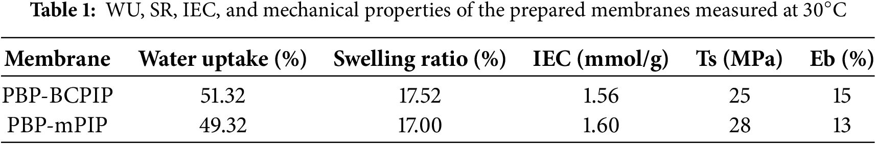
Water uptake (WU) is an essential constraint for assessing the capability of AEMs as it influences the conduction of hydroxide ions and mechanical robustness of the prepared membrane. Too much water uptake can lead to a decline in mechanical properties, which is undesirable. As shown in Fig. 2a, the WU of the PBP-BCPIP is higher than that of the PBP-mPIP membrane at 30°C, the former being 51% while the latter 49%. With elevated temperature, the WU of PBP-BCPIP membrane increases and reaches 76% at 80°C. However, the WU of the PBP-mPIP membrane does not change with temperature. This difference can be attributed to the presence of crown ether modified cation in the PBP-BCPIP membrane, which enhances its ability to absorb and store water and the polymer matrix is relatively rigid, limiting water uptake at low temperature. Although the high WU benefits conductivity, it may compromise mechanical robustness under long-term cycling. Optimizing hydration control strategies, such as partial crosslinking or blending, should be considered in future work.
Figure 2: The (a) WU and (b) SR of PBP-BCPIP and PBP-mPIP membranes
Despite a significantly higher water uptake as discussed above, the PBP-BCPIP membrane shows a swelling ratio only slightly higher than that of PBP-mPIP; this is observed in Fig. 2b and the reason may lie in the hollow structure of crown ether, which can help to store water and thus does not lead to increased spacing between polymer chains; water molecules may also be stored in the free volume in the membrane caused by the bulky crown ether moieties. Furthermore, the PBP-BCPIP membrane shows a slight change in swelling with temperature, as seen in Fig. 2b. The results demonstrate that the PBP-BCPIP membrane has better water uptake properties compared to PBP-mPIP, and have good resistance to swelling. These findings are crucial for developing efficient AEMs with improved performance.
The mechanical properties of the hydrated membranes of PBP-mPIP and PBP-BCPIP were evaluated and are summarized in Table 1. The results indicate that both membranes possess good tensile strength, exceeding 25 MPa. However, it is noteworthy that the PBP-BCPIP membrane, which contains crown ether units combined with piperidinium, has a lower tensile strength but greater elongation at break related to PBP-mPIP. This can be ascribed to the higher water absorption of PBP-BCPIP, which leads to water plasticization. While elongation improvement is desirable, the reduced tensile strength suggests a trade-off that must be balanced. These results suggest that the combination of crown ether units into cationic groups can effectively regulate the WU and SR of AEMs, giving better membrane ductility without much sacrifice of mechanical strength.
The microstructure of AEMs is an vital factor determining their ionic conductivity and stability [44]. TEM was used to analyze the phase separation morphology of the prepared PBP-BCPIP and PBP-mPIP membranes. As revealed in the Fig. 3, PBP-BCPIP membrane has a distinct microphase separation morphology compared to PBP-mPIP. This morphology is mainly due to the strong polarity difference between hydrophobic and hydrophilic structure [4]. The crown ether group and the ionic group in PBP-BCPIP membrane have hydrophilicity, while the floride containing main chain has hydrophobicity. The strong polarity difference between the two phases results in a high driving force for ion aggregation, leading to significant phase separation behavior. The dark regions observed in Fig. 3 represent the hydrophilic regions that form large and interconnected ion clusters. These clusters create continuous and orderly ion passage pathways, which are essential for the efficient transport of ions in the AEM. The well-defined microstructure of PBP-BCPIP membrane is expected to enhance its ionic conductivity and durability in AEMFCs.
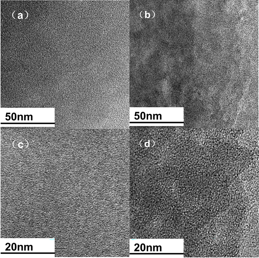
Figure 3: TEM images of PBP-mPIP (a,c) and PBP-BCPIP (b,d)
In order to examine how the crown ether modified piperidine affects ion transport, a comparison was made between the hydroxide conductivity of PBP-BCPIP and PBP-mPIP. Fig. 4 shows the correlation between the hydroxide conductivity and temperature of PBP-BCPIP and PBP-mPIP. As ions are more active and move faster at high temperatures, all membranes exhibit a quick increase in conductivity as the temperature increases from 30°C to 80°C. Specifically, the conductivity of PBP-BCPIP increases from 59 to 123 mS cm−1, which is much higher than that of PBP-mPIP and also better than or comparable with literature results [19,21]. This can be ascribed to the fact that the high WU brought about by the crown ether group can effectively assist in ion conduction [45], and the introduction of crown ether enhances the microphase separation within the membrane [46]. The evolution of ionic conductivity at high temperatures is controlled by the Arrhenius law. The obvious activation energy of PBP-BCPIP for conducting OH− ion is 13.05 kJ mol−1, while that of PBP-mPIP is 14.44 kJ mol−1. The lower activation energy of PBP-BCPIP indicates that it requires less energy to conduct OH− ions, which makes it more favorable for use in AEMFCs.
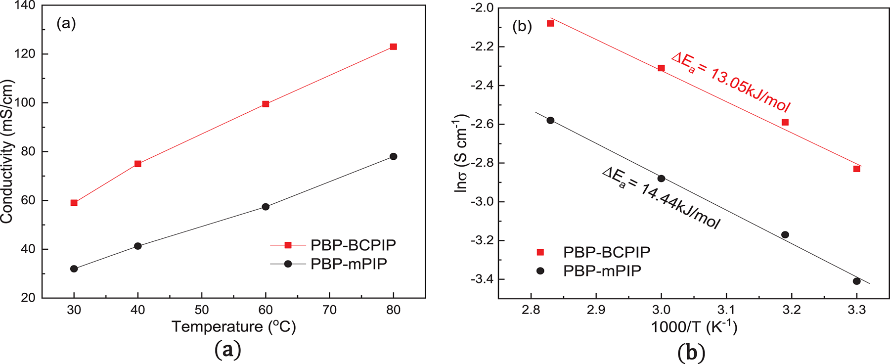
Figure 4: (a) Hydroxide ion conductivity and (b) Arrhenius plots of the PBP-BCPIP and PBP-mPIP membranes
The thermal decomposition of the membrane is investigated by TGA. The results are shown in the Fig. 5, which indicates that the thermal decomposition of the membrane can be divided into three phases. In the first stage, the weight loss occurs below 120°C, which is ascribed to the evaporation of residual solvent and water in the membrane. The second stage occurs at a temperature range of 170°C–400°C, where the mass loss represents the thermal decomposition of crown ether and piperidine groups. Finally, in the third stage, the mass loss occurs at a temperature higher than 400°C, resulting from the decomposition of the PBP polymer. It is worth pointing out that the working temperature of AEMFC is typically below 100°C [44,47], thus the thermal strength of PBP-BCPIP membrane meets the normal working requirements of fuel cells. Overall, the authors provide important insights into the thermal stability of the PBP-BCPIP membrane, which is a crucial property for its potential application in fuel cells.
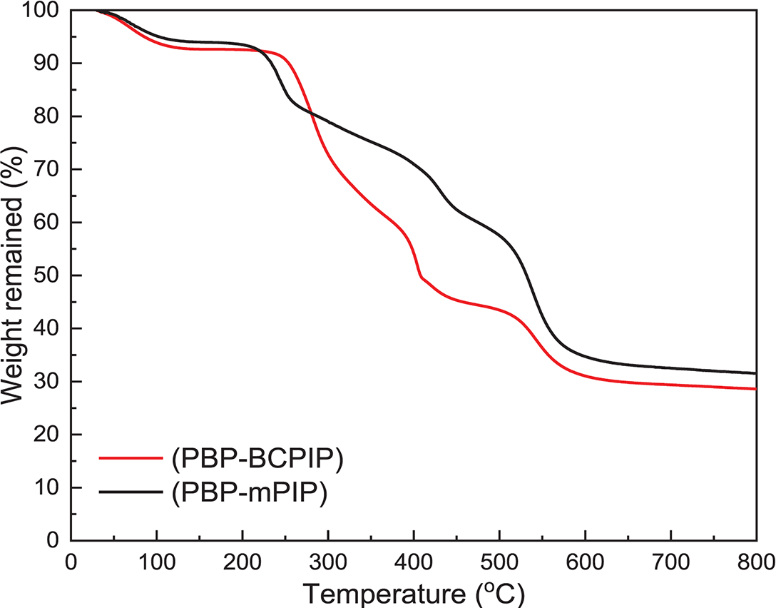
Figure 5: Thermogravimetric analysis (TGA) of the PBP-BCPIP and PBP-mPIP
Evaluation of the long term stability of AEMs in alkaline fuel cells is crucial for their practical application. The alkaline stability of the prepared PBP-BCPIP and PBP-mPIP membranes was examined by submerging them in 1 mol L−1 NaOH solution at 80°C. As shown in Fig. 6, the conductivity retention rates of PBP-BCPIP and PBP-mPIP membranes after 960 h alkali treatment were 86% and 83%, respectively, indicating that the membrane with the crown ether modified piperidinium cation had better alkali stability.
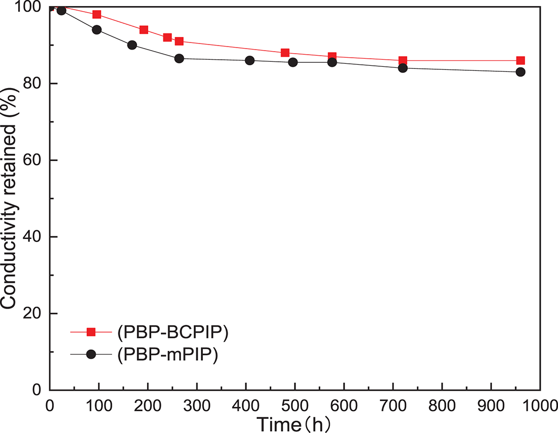
Figure 6: Conductivity retention of the PBP-BCPIP and PBP-mPIP membranes after treatments in 1 mol L−1 NaOH solution at 80°C for 960 h
The microphase separation structure of the PBP-BCPIP membrane plays a crucial role in its alkali stability. The hydrophilic phase crown ether can make the ionic group combine with more water molecules, thus diluting the concentration of OH− and decreasing the attack on the cationic group. In addition, the hydrophobic phase can reduce the attack of OH− to a certain extent [27,48]. The conductivity of the PBP-BCPIP membrane also depends on the assistance of the crown ether group. Although the crown ether group will not be degraded, the hydroxyl radical can attack the α-C or β-H, leading to the degradation of cation on the main chain. This can cause the tail piperidium ion and crown ether as degradation products to fall off with the spacer chain. Despite these potential degradation pathways, the PBP-BCPIP membrane still demonstrated good alkali stability. The membrane structure was analyzed using the 1H NMR spectra before and after undergoing alkaline treatment. The results depicted in Fig. 7 indicate that there was slight change observed before and after alkali treatment. The high intensity of the peaks at 1.2 and 0.8 ppm are attributed to the degradation of the pyridine ring via Hofmann degradation. Additionally, the new peak appeared at 3 ppm can be attributed to an increase in nucleophilic substitution degradation. This type of substitution produces minor hydroxylated or demethylated fragments, which have been reported as a typical degradation pathway in poly(arylene piperidinium) and related membranes under alkaline conditions. Importantly, the very low intensity of this peak compared with the main polymer signals indicates that only a small fraction of sites is affected. This observation is consistent with the high conductivity retention (~85%) and stable IEC values after long-term alkaline exposure [49].
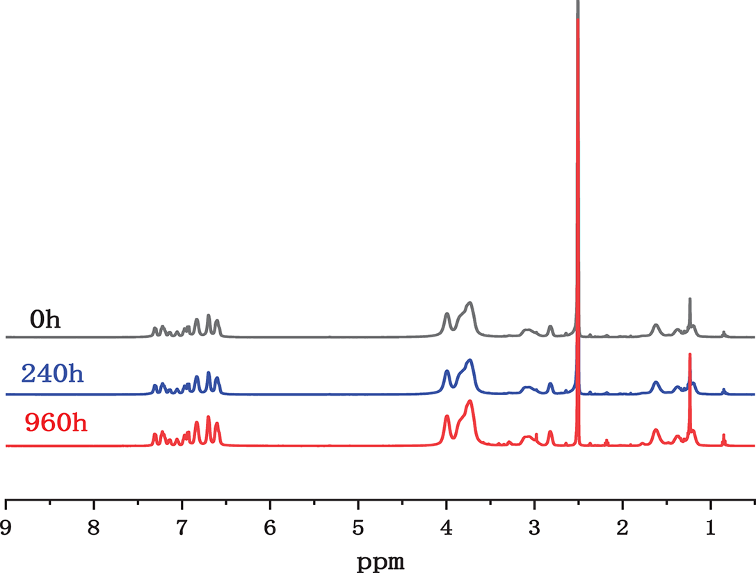
Figure 7: The 1H NMR spectra of the PBP-BCPIP membranes after 0, 240 and 960 h of alkali-treatment at 80°C in 1 molar NaOH solution
The H2-O2 fuel cell performance of PBP-BCPIP membrane was evaluated owing to its excellent conductivity and alkali stability. Fig. 8 presents the polarization curve and power density results of the fuel cells assembled with PBP-BCPIP and PBP-mPIP. It is seen that PBP-BCPIP fuel cell yielded a maximum power density of 558 mW cm−2 at 60°C with a current density of 1040 mA cm−2. In contrast, the PBP-mPIP cell only attained a peak power density of only 320 mW cm−2. The open circuit voltage of PBP-BCPIP based fuel cell was found to be 0.98 V, reasonably close to theoretical potential of the cell, indicating good ability of the membrane to prevent fuel crossover. The non-linear iR region arises from a combination of membrane resistivity and interfacial resistance between the membrane and electrodes. The two-slope behavior may reflect different regimes: partial saturation of ion transport channels at intermediate current densities (250–600 mA cm−2) and additional mass transport limitations at higher current densities (>600 mA cm−2). It is worth noting that the performance of fuel cells is influenced by multiple components in addition to the membrane, and thus cannot be directly correlated with membrane performance. Nevertheless, the results suggest that PBP-BCPIP has great potential as an AEM in fuel cells due to its high power density and good H2-O2 tightness.
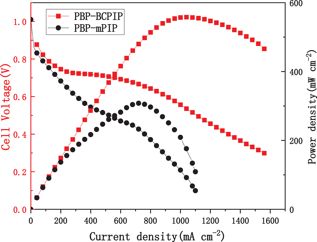
Figure 8: The fuel cell performance of PBP-BCPIP membrane at 60°C (100% relative humidity) and with zero backpressure
The use of bi-crown-ether modified piperidinium cation in enhancing the performance of AEMs has been demonstrated in this work. The combination of bi-crown-ether with piperidinium can enhance the hydrophilicity of the resulting side chains, and promote microphase separation for constructing hydroxide ion pathway. As a result, the PBP-BCPIP membrane exhibited a high water uptake (51% at 30°C) but reasonable swelling (17% at 30°C) and mechanical strength of 25 MPa; its hydroxide conductivity can reach 124 mS cm−1 at 80°C with a low IEC of 1.56 mmol g−1. The membrane also displayed good alkaline stability, retaining 85% of its hydroxide conductivity after soaking in 1 mol L−1 NaOH solution at 80°C for 960 h. This work provides a novel and effective strategy for high-performance anion exchange membrane design and may benefit the development of alkaline membrane fuel cells.
Acknowledgement: The authors would like to express their sincere gratitude to Dalian University of Technology, Panjin Campus, for providing the infrastructure, laboratory facilities, and characterization instruments utilized in this research.
Funding Statement: This work was supported by the following research grant. The Creative Group Fund of National Natural Science Foundation of China (Grant no. 22021005), the Fund of National Natural Science Foundation of China (Grant no. 22075037), and HEC for National Research Program for Universities (NRPU) Project no. 14840.
Author Contributions: Minghao Yuan: methodology, investigation, writing—original draft. Lingling Ma, Lv Li and Shoutao Gong: writing—review & editing, conceptualization, formal Analysis. Fengxiang Zhang: project administration, funding acquisition, investigation. Lei Bai, Yanzhen Ren, Xinli Zhang: data curation, investigation. Naeem Akhtar Qaisrani: supervision, review & editing, investigation. All authors reviewed the results and approved the final version of the manuscript.
Availability of Data and Materials: The authors confirm that the data supporting the findings of this study are available within the article.
Ethics Approval: This article does not contain studies with human or animal participants.
Conflicts of Interest: The authors declare no conflicts of interest to report regarding the present study.
References
1. Gong S, Bai L, Li L, Qaisrani NA, Ma L, He G, et al. Block copolymer anion exchange membrane containing polymer of intrinsic microporosity for fuel cell application. Int J Hydrogen Energy. 2021;46(2):2269–81. doi:10.1016/j.ijhydene.2020.10.068. [Google Scholar] [CrossRef]
2. Chu X, Liu J, Miao S, Liu L, Huang Y, Tang E, et al. Crucial role of side-chain functionality in anion exchange membranes: properties and alkaline fuel cell performance. J Membr Sci. 2021;625:119172. doi:10.1016/j.memsci.2021.119172. [Google Scholar] [CrossRef]
3. Yang B, Zhang C. Progress in constructing high-performance anion exchange membrane: molecular design, microphase controllability and in-device property. Chem Eng J. 2023;457(3):141094. doi:10.1016/j.cej.2022.141094. [Google Scholar] [CrossRef]
4. Ozawa Y, Shirase Y, Otsuji K, Miyatake K. Tuning hydrophobic composition in terpolymer-based anion exchange membranes to balance conductivity and stability. Mol Syst Des Eng. 2022;7(7):798–808. doi:10.1039/d2me00027j. [Google Scholar] [CrossRef]
5. Zhang X, Yu Z, Tang J, Huang J, Tang X, Chen Y, et al. Advances in composite anion-exchange membranes for fuel cells: modification approaches and synthesis strategies. Mater Today Chem. 2025;43:102496. doi:10.1016/j.mtchem.2024.102496. [Google Scholar] [CrossRef]
6. Qaisrani NA, Ma L, Hussain M, Liu J, Li L, Zhou R, et al. Hydrophilic flexible ether containing, cross-linked anion-exchange membrane quaternized with DABCO. ACS Appl Mater Interfaces. 2020;12(3):3510–21. doi:10.1021/acsami.9b15435. [Google Scholar] [PubMed] [CrossRef]
7. Ma W, Tian L, Zhang Q, Shangguan L, Wang F, Zhu H. Hydrophilic and hydrophobic dual-side-linked poly(carbazole-butanedione) anion exchange membranes for water electrolysis and fuel cells applications. J Membr Sci. 2025;722(39):123840. doi:10.1016/j.memsci.2025.123840. [Google Scholar] [CrossRef]
8. Song W, Zhang X, Yang C, Yang Z, Wu L, Ge X, et al. Alkaline membranes toward electrochemical energy devices: recent development and future perspectives. ACS Cent Sci. 2023;9(8):1538–57. doi:10.1021/acscentsci.3c00597. [Google Scholar] [PubMed] [CrossRef]
9. Chu X, Miao S, Zhou A, Liu S, Liu L, Li N. A strategy to design quaternized poly(2,6-dimethyl-1,4-phenylene oxide) anion exchange membranes by atom transfer radical coupling. J Membr Sci. 2022;649:120397. doi:10.1016/j.memsci.2022.120397. [Google Scholar] [CrossRef]
10. Sui Z, Wang Z, Wang S, Wang Y. Side-chain type PPO based anion exchange membrane with steric hindrance containing dual conduction sites. Electrochim Acta. 2024;496:144511. doi:10.1016/j.electacta.2024.144511. [Google Scholar] [CrossRef]
11. Ren J, Xu J, Ju M, Chen X, Zhao P, Meng L, et al. Long-term durable anion exchange membranes based on imidazole-functionalized poly(ether ether ketone) incorporating cationic metal-organic framework. Adv Powder Mater. 2022;1(2):100017. doi:10.1016/j.apmate.2021.11.004. [Google Scholar] [CrossRef]
12. Ayaz S, Yao ZY, Chen YJ, Yu HY. Preparation of poly(arylene ether ketone) based anion exchange membrane with pendant pyrimidinium and pyridazinium cation derivatives for alkaline fuel cell. J Membr Sci. 2022;659:120778. doi:10.1016/j.memsci.2022.120778. [Google Scholar] [CrossRef]
13. Miyanishi S, Yamaguchi T. Ether cleavage-triggered degradation of benzyl alkylammonium cations for polyethersulfone anion exchange membranes. Phys Chem Chem Phys. 2016;18(17):12009–23. doi:10.1039/c6cp00579a. [Google Scholar] [PubMed] [CrossRef]
14. Chen N, Wang HH, Kim SP, Kim HM, Lee WH, Hu C, et al. Poly(fluorenyl aryl piperidinium) membranes and ionomers for anion exchange membrane fuel cells. Nat Commun. 2021;12(1):2367. doi:10.1038/s41467-021-22612-3. [Google Scholar] [PubMed] [CrossRef]
15. Cha MS, Park JE, Kim S, Han SH, Shin SH, Yang SH, et al. Poly(carbazole)-based anion-conducting materials with high performance and durability for energy conversion devices. Energy Environ Sci. 2020;13(10):3633–45. doi:10.1039/d0ee01842b. [Google Scholar] [CrossRef]
16. Fan J, Willdorf-Cohen S, Schibli EM, Paula Z, Li W, Skalski TJG, et al. Poly(bis-arylimidazoliums) possessing high hydroxide ion exchange capacity and high alkaline stability. Nat Commun. 2019;10(1):2306. doi:10.1038/s41467-019-10292-z. [Google Scholar] [PubMed] [CrossRef]
17. Willdorf-Cohen S, Mondal AN, Dekel DR, Diesendruck CE. Chemical stability of poly(phenylene oxide)-based ionomers in an anion exchange-membrane fuel cell environment. J Mater Chem A. 2018;6(44):22234–9. doi:10.1039/c8ta05785k. [Google Scholar] [CrossRef]
18. Dekel DR, Willdorf S, Ash U, Amar M, Pusara S, Dhara S, et al. The critical relation between chemical stability of cations and water in anion exchange membrane fuel cells environment. J Power Sources. 2018;375:351–60. doi:10.1016/j.jpowsour.2017.08.026. [Google Scholar] [CrossRef]
19. Xu S, Wei W, Su X, He R. Crown-ether block copolymer based poly(isatin terphenyl) anion exchange membranes for electrochemical energy conversion devices. Chem Eng J. 2023;455(10):140776. doi:10.1016/j.cej.2022.140776. [Google Scholar] [CrossRef]
20. Pan J, Chen C, Li Y, Wang L, Tan L, Li G, et al. Constructing ionic highway in alkaline polymer electrolytes. Energy Environ Sci. 2014;7(1):354–60. doi:10.1039/c3ee43275k. [Google Scholar] [CrossRef]
21. Zhang H, Zhang Y, Zhang F, Ge X, Song W, Wei C, et al. Enhancing side chain swing ability by novel all-carbon twisted backbone for high performance anion exchange membrane at relatively low IEC level. J Membr Sci Lett. 2021;1(2):100007. doi:10.1016/j.memlet.2021.100007. [Google Scholar] [CrossRef]
22. Li J, Li W, Wang X, Pan D, Sa R, Xiao M, et al. A microphase separation anion exchange membrane based on poly(terphenyl piperidinium)/cationic polyelectrolyte for high-performance AEMWEs. J Membr Sci. 2025;730(13):124206. doi:10.1016/j.memsci.2025.124206. [Google Scholar] [CrossRef]
23. Lai AN, Ni L, Wang WJ, Wang QX, Hu PC, Zhou SF. Improved property of block copolymer-based anion exchange membranes by attaching multi-ion flexible strings. Int J Hydrogen Energy. 2024;94:331–40. doi:10.1016/j.ijhydene.2024.11.123. [Google Scholar] [CrossRef]
24. Liu L, Huang G, Kohl PA. Anion conducting multiblock copolymers with multiple head-groups. J Mater Chem A. 2018;6(19):9000–8. doi:10.1039/c8ta00753e. [Google Scholar] [CrossRef]
25. Ahmed Mahmoud AM, Miyatake K. Optimization of the pendant chain length in partially fluorinated aromatic anion exchange membranes for alkaline fuel cells. J Mater Chem A. 2018;6(29):14400–9. doi:10.1039/c8ta04310h. [Google Scholar] [CrossRef]
26. Chen W, Wang X, Li T, Yan X, Wu X, Zhang Y, et al. Amphiphilic cone-shaped cationic calix[4]arene composite anion exchange membranes with continuous ionic channels. J Membr Sci. 2021;640:119815. doi:10.1016/j.memsci.2021.119815. [Google Scholar] [CrossRef]
27. Du X, Zhang H, Yuan Y, Wang Z. Constructing micro-phase separation structure to improve the performance of anion-exchange membrane based on poly(aryl piperidinium) cross-linked membranes. J Power Sources. 2021;487:229429. doi:10.1016/j.jpowsour.2020.229429. [Google Scholar] [CrossRef]
28. Ma L, Qaisrani NA, Hussain M, Li L, Jia Y, Ma S, et al. Cyclodextrin modified, multication cross-linked high performance anion exchange membranes for fuel cell application. J Membr Sci. 2020;607:118190. doi:10.1016/j.memsci.2020.118190. [Google Scholar] [CrossRef]
29. Kim Y, Moh LCH, Swager TM. Anion exchange membranes: enhancement by addition of unfunctionalized triptycene poly(ether sulfone)s. ACS Appl Mater Interfaces. 2017;9(49):42409–14. doi:10.1021/acsami.7b13058. [Google Scholar] [PubMed] [CrossRef]
30. Zhang X, Guo J, Chu X, Fang C, Huang Y, Liu L, et al. Mechanically flexible bulky imidazolium-based anion exchange membranes by grafting PEG pendants for alkaline fuel cells. J Membr Sci. 2022;659:120820. doi:10.1016/j.memsci.2022.120820. [Google Scholar] [CrossRef]
31. Xue B, Wang Q, Zheng J, Li S, Zhang S. Bi-guanidinium-based crosslinked anion exchange membranes: synthesis, characterization, and properties. J Membr Sci. 2020;601:117923. doi:10.1016/j.memsci.2020.117923. [Google Scholar] [CrossRef]
32. Kumari M, Douglin JC, Dekel DR. Crosslinked quaternary phosphonium-functionalized poly(ether ether ketone) polymer-based anion-exchange membranes. J Membr Sci. 2021;626:119167. doi:10.1016/j.memsci.2021.119167. [Google Scholar] [CrossRef]
33. Duan X, Zhu X, Li G, Xia R, Qian J, Ge Q. Pyrrolidinium-based hyperbranched anion exchange membranes with controllable microphase separated morphology for alkaline fuel cells. Macromol Rapid Commun. 2023;44(3):e2200669. doi:10.1002/marc.202200669. [Google Scholar] [PubMed] [CrossRef]
34. Tang W, Yang Y, Liu X, Dong J, Li H, Yang J. Long side-chain quaternary ammonium group functionalized polybenzimidazole based anion exchange membranes and their applications. Electrochim Acta. 2021;391(13):138919. doi:10.1016/j.electacta.2021.138919. [Google Scholar] [CrossRef]
35. Chehardoli G, Bahmani A. The role of crown ethers in drug delivery. Supramol Chem. 2019;31(4):221–38. doi:10.1080/10610278.2019.1568432. [Google Scholar] [CrossRef]
36. Kazemabad M, Verliefde A, Cornelissen ER, D’Haese A. Crown ether containing polyelectrolyte multilayer membranes for lithium recovery. J Membr Sci. 2020;595(16):117432. doi:10.1016/j.memsci.2019.117432. [Google Scholar] [CrossRef]
37. Li J, Yim D, Jang WD, Yoon J. Recent progress in the design and applications of fluorescence probes containing crown ethers. Chem Soc Rev. 2017;46(9):2437–58. doi:10.1039/c6cs00619a. [Google Scholar] [PubMed] [CrossRef]
38. Christy FA, Shrivastav PS. Conductometric studies on cation-crown ether complexes: a review. Crit Rev Anal Chem. 2011;41(3):236–69. doi:10.1080/10408347.2011.589284. [Google Scholar] [CrossRef]
39. Li N, Chen F, Shen J, Zhang H, Wang T, Ye R, et al. Buckyball-based spherical display of crown ethers for de novo custom design of ion transport selectivity. J Am Chem Soc. 2020;142(50):21082–90. doi:10.1021/jacs.0c09655. [Google Scholar] [PubMed] [CrossRef]
40. Yuan Y, Du X, Zhang H, Wang H, Wang Z. Poly(isatin biphenylene) polymer containing ferrocenium derivatives for anion exchange membrane fuel cell. J Membr Sci. 2022;642:119986. doi:10.1016/j.memsci.2021.119986. [Google Scholar] [CrossRef]
41. Hu C, Park JH, Kim HM, Wang HH, Bae JY, Liu ML, et al. Robust and durable poly(aryl-co-aryl piperidinium) reinforced membranes for alkaline membrane fuel cells. J Mater Chem A. 2022;10(12):6587–95. doi:10.1039/d2ta00196a. [Google Scholar] [CrossRef]
42. Chen N, Park JH, Hu C, Wang HH, Kim HM, Kang NY, et al. Di-piperidinium-crosslinked poly(fluorenyl-co-terphenyl piperidinium)s for high-performance alkaline exchange membrane fuel cells. J Mater Chem A. 2022;10(7):3678–87. doi:10.1039/d1ta10178a. [Google Scholar] [CrossRef]
43. Zheng X, Song S, Yang J, Wang J, Wang L. 4-formyl dibenzo-18-crown-6 grafted polyvinyl alcohol as anion exchange membranes for fuel cell. Eur Polym J. 2019;112:581–90. doi:10.1016/j.eurpolymj.2018.10.020. [Google Scholar] [CrossRef]
44. Xu F, Su Y, Lin B. Progress of alkaline anion exchange membranes for fuel cells: the effects of micro-phase separation. Front Mater. 2020;7:4. doi:10.3389/fmats.2020.00004. [Google Scholar] [CrossRef]
45. Zhang J, Zhang K, Liang X, Yu W, Ge X, Shehzad MA, et al. Self-aggregating cationic-chains enable alkaline stable ion-conducting channels for anion-exchange membrane fuel cells. J Mater Chem A. 2021;9(1):327–37. doi:10.1039/d0ta11011f. [Google Scholar] [CrossRef]
46. Liu D, Lin L, Xie Y, Pang J, Jiang Z. Anion exchange membrane based on poly(arylene ether ketone) containing long alkyl densely quaternized carbazole derivative pendant. J Membr Sci. 2021;623:119079. doi:10.1016/j.memsci.2021.119079. [Google Scholar] [CrossRef]
47. Douglin JC, Varcoe JR, Dekel DR. A high-temperature anion-exchange membrane fuel cell. J Power Sources Adv. 2020;5:100023. doi:10.1016/j.powera.2020.100023. [Google Scholar] [CrossRef]
48. Xue J, Liu X, Zhang J, Yin Y, Guiver MD. Poly(phenylene oxide)s incorporating N-spirocyclic quaternary ammonium cation/cation strings for anion exchange membranes. J Membr Sci. 2020;595:117507. doi:10.1016/j.memsci.2019.117507. [Google Scholar] [CrossRef]
49. Long C, Wang Z, Zhu H. High chemical stability anion exchange membrane based on poly(aryl piperidiniumeffect of monomer configuration on membrane properties. Int J Hydrogen Energy. 2021;46(35):18524–33. doi:10.1016/j.ijhydene.2021.02.209. [Google Scholar] [CrossRef]
Cite This Article
 Copyright © 2025 The Author(s). Published by Tech Science Press.
This work is licensed under a Creative Commons Attribution 4.0 International License , which permits unrestricted use, distribution, and reproduction in any medium, provided the original work is properly cited.
 Downloads
 Citation Tools