
 Submit a Paper
 Propose a Special lssue
 Open Access
ARTICLE

Optimized General Uniform Quantum State Preparation
University of Maryland, College Park, Maryland, 20742, USA
* Corresponding Author: Mark Ariel Levin. Email:
Journal of Quantum Computing 2024, 6, 15-24. https://doi.org/10.32604/jqc.2024.047423
Received 05 November 2023; Accepted 16 January 2024; Issue published 24 April 2024
 View Full Text
 Download PDF
Abstract
Quantum algorithms for unstructured search problems rely on the preparation of a uniform superposition, traditionally achieved through Hadamard gates. However, this incidentally creates an auxiliary search space consisting of nonsensical answers that do not belong in the search space and reduce the efficiency of the algorithm due to the need to neglect, un-compute, or destructively interfere with them. Previous approaches to removing this auxiliary search space yielded large circuit depth and required the use of ancillary qubits. We have developed an optimized general solver for a circuit that prepares a uniform superposition of any N states while minimizing depth and without the use of ancillary qubits. We show that this algorithm is efficient, especially in its use of two wire gates, and that it has been verified on an IonQ quantum computer and through application to a quantum unstructured search algorithm.Keywords
All quantum unstructured search algorithms begin with a uniform superposition representing the search space that is then gradually modified through interference to arrive at a superposition of only correct answers. Typically, uniform state preparation is performed using Hadamard gates, which put a wire into equal superposition of 0 and 1. However, using Hadamard gates to create a uniform superposition means that the size of the search space can only be
As mentioned in [1], there is need in some cases for a restricted search space. Mukherjee describes a process to find a potential unitary of an initializer for such a restricted search space, namely the Gram-Schmidt procedure. While this works to run this process on a simulator, it cannot be run on an actual quantum computer without first implementing a sequence of gates for this unitary. He gives [2–4] as examples to implement the unitary but these do not leverage what is known about the search space and thus do not maximize depth efficiency. In searching for an implementation, we discovered that another potential unitary for the initializer is a Quantum Fourier Transform with an
We developed an algorithm that accomplishes this while minimizing 2-wire gate complexity.
The current optimal solver for general non-uniform state-preparation is [5]. For a state represented by d wires, the depth of circuits created by this solver is
As an example of an unstructured search application of our solver, we will focus hereafter specifically on Graph Coloring Problems. A graph G consists of a set of vertices/nodes V and a set of edges E. Each vertex v has a set of
We have implemented a Grover’s Algorithm [7] based approach to such problems as described in [1] to demonstrate an application of our algorithm. For this implementation, each vertex
Using Hadamard gates for state preparation means a search space that is
which is significantly greater than or equal to the restricted search space
Consequently, using Hadamard gates for state preparation can mean a significant reduction in efficiency, as the number of repetitions needed is proportional to the square root of the size of the search space. If instead we create a restricted superposition of any given number of states, we can significantly decrease the number of repetitions of Grover’s Algorithm that are needed.
This optimization is applicable not only for Graph Coloring Problems, but (at minimum) all applications of Grover’s Algorithm. Previously, Grover’s Algorithm has been successfully employed to obtain quantum speedup for various combinatorial optimization problems ([8–12]) all of which can potentially be further optimized via this modification. One thing to note for Grover’s Algorithm in particular, is that the sub-circuit for generating the restricted superposition is needed not only for the initializer but for the mirror of the diffuser in each repetition, making it very important to minimize the number of inefficient 2 wire gates. We believe we have developed an optimal general case solver for the uniform state preparation circuit of any possible N.
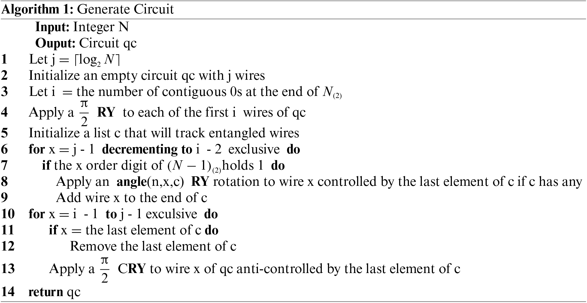
The circuit for the uniform superposition of N states needs j =
A subsequent “downward arc” back-fills the remaining elements. First the lowest order wire outside of the first i wires is put into equal superposition anti-controlled by the next lowest order wire that was rotated in the upward arc (recorded in line 9). This is because among the states in the superposition where that control wire holds 0 at this point in the process, half should hold 1 in the target wire. This is repeated on each wire in order of increasing magnitude, excluding the highest order wire, each controlled by the next lowest order wire that was entangled in the upward arc.
The desired probability of observing 1 on the highest order wire is the proportion of states in the desired superposition that have 1 on that bit, thus p =
The number of 2-wire gates required to create a uniform superposition for any given N is equal to count1(N − 1) – 2 maxp(N) +
which is
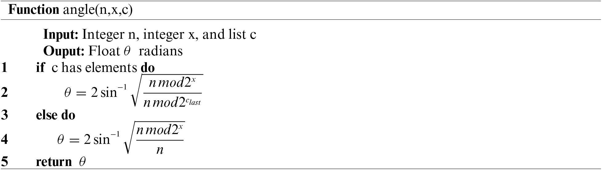
Suppose we wanted a superposition of 7 states, see Fig. 1. This superposition consists of elements 0 through 6, which are represented in binary as 000, 001, 010, 011, 100, 101, and 110. The wires that represent the value of each bit are labeled in order of decreasing magnitude,
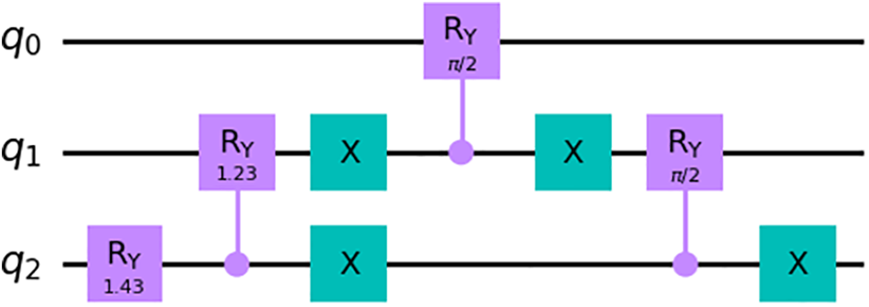
Figure 1: Circuit to initialize a uniform superposition of 7 states
Suppose instead that we wanted a superposition of 22 states, see Fig. 2. We follow the same general process with a few modifications. First, because 22 is even, the superposition has an even distribution of 1 and 0 in
Figure 2: Circuit to initialize a uniform superposition of 22 states
3.1 Simulator vs. Quantum Computer
All results in this section come from the circuit for N = 27, see Fig. 3.
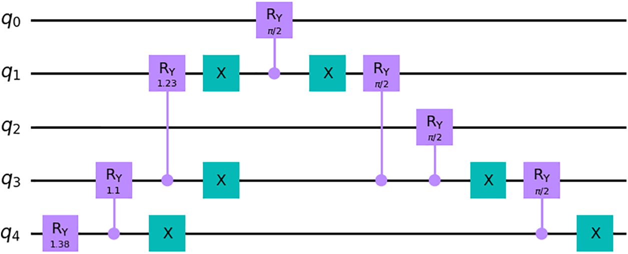
Figure 3: Circuit to initialize a uniform superposition of 27 states
When run on a noiseless simulator, the algorithm creates a perfect superposition of N states, however, each noisy simulator has a different consistent bias when running, see Fig. 4a, likely stemming from inexact rotation angles. Each quantum computer also has a different bias that is consistent across runs in the same calibration, see Fig. 4b. However, when a histogram for the frequency of each output is constructed with all of the results from the simulators and the machines, see Fig. 4c, the mean bias is very small, though the variance varies greatly between them. This indicates that the bias results from flaws in the hardware, and that the algorithm is sound in principle.
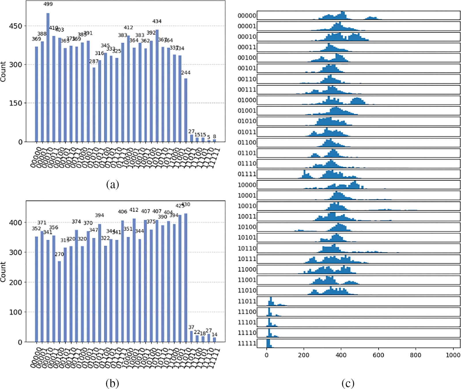
Figure 4: Frequency of each state in the superposition for N = 27 with 10,000 shots when run on (a) IonQ’s aria noise simulator and (b) their aria machine. (c) Histogram for each state in the superposition for N = 27 with 10,000 shots and results combined from IonQ’s harmony and aria noise simulators, their harmony machine, and two different calibrations of their aria machine across 100 runs of each
It may be of note that the bias when run on a quantum computer is not consistent across calibrations. This was discovered when a group of identical runs on IonQ’s harmony machine were spread out over the course of 2 weeks and thus were run under different calibrations, see Fig. 5. In this way, the circuits generated by this solver can incidentally be used as a test of the fidelity of a calibration including 2-wire gates.
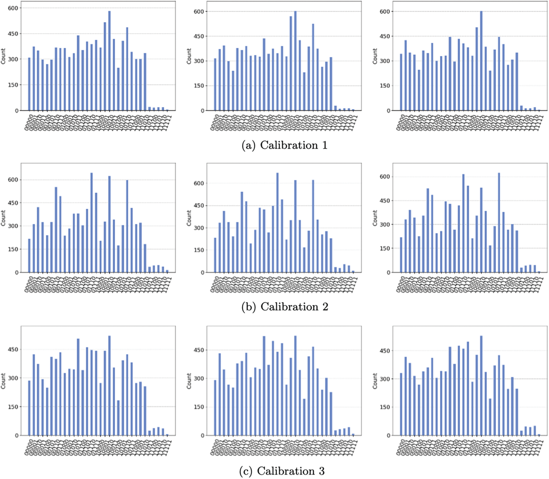
Figure 5: Consistent bias across consecutive runs of N = 27 on IonQ harmony but not across calibrations
3.2 Simulated Modified Grover’s Algorithm
When applying this process to Grover’s Algorithm for Graph Coloring problems, we saw a remarkable improvement in efficiency that was polynomially proportional to
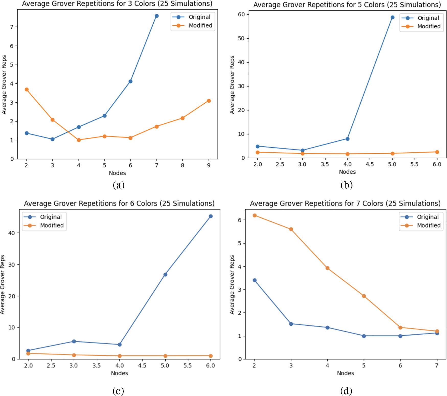
Figure 6: Average number of Grover repetitions needed to observe correct answers via a stochastic iterative stepping process as suggested in [13] for a line graph with (a) 3, (b) 5, (c) 6, and (d) 7 colors. These results were simulated on the qiskit Aer simulator with the qiskit FakeVigo noise model. Other approaches to estimate repetitions include [14–16]
Unfortunately, trivial graphs predominate in these experiments because of the limitations of the simulator on which they were conducted. When more nodes were attempted than shown in the datapoints, the simulator failed either due to time out, or simply being unable to handle the number of wires required, see Eq. (2). It is notable that timeout always occurred with fewer or equal nodes for the original version than for the modified version. Graphs where
With this modified version of Grover’s Algorithm, the initializer and the mirror of the diffuser both have increased depth in each iteration. We have already discussed how we limit the depth of our circuits so that this increased depth is minimized, but the increase in depth is also negligible in comparison to the depth of the oracle and the decomposition of the multi-controlled CNOT in the diffuser, both of which are unchanged by our modification. The data in Fig. 6 demonstrate that as a trade-off for this slight increase in the depth of each iteration, we can significantly reduce the number of iterations required to reach a correct solution. Overall, this balances out to significantly decrease the overall depth of Grover’s Algorithm.
We were able to accomplish a significant improvement in the efficiency of quantum unstructured search by eliminating the auxiliary search space created by traditional methods of state preparation while minimizing the number of 2-wire gates required to do so. Although we have only provided the example of a Grover’s Algorithm approach to graph coloring problems as a viable application, colleagues of ours have already begun making use of these state preparations to improve the efficiency of quantum walk, machine learning, and other applications. This solver can be used to varying degrees of effect to modify any algorithm that requires a uniform state preparation that is unattainable via simple Hadamard superposition.
Acknowledgement: Thank you to Dr. Franz Klein from University of Maryland for his advisory role, helping me to consider potential applications of my work and for his advice and revisions during the writing of this paper.
Funding Statement: The author received no specific funding for this work.
Author Contributions: Mark Levin was the sole researcher and author of this work.
Availability of Data and Materials: All data in this work can be generated using https://github.com/TheMLevin/GroverGraphSolver.
Conflicts of Interest: The authors declare that they have no conflicts of interest to report regarding the present study.
References
1. S. Mukherjee, “A grover search-based algorithm for the list coloring problem,” arXiv:2108.09061, 2022. [Google Scholar]
2. R. Roberts, C. K. Li, and X. Yin, “Decomposition of unitary matrices and quantum gates,” Int. J. Quantum. Inf., vol. 11, no. 1, pp. 1350015, 2013. doi: 10.48550/arXiv.1210.7366. [Google Scholar] [CrossRef]
3. Mikko Mött önen et al., “Quantum circuits for general multiqubit gates,” Phys. Rev. Lett., vol. 93, no. 13, pp. 130502, 2004. doi: 10.1142/S0219749913500159. [Google Scholar] [CrossRef]
4. Mikko Mött önen Juha, J. J. Vartiainen, and M. M. Salomaa, “Efficient decomposition of quantum gates,” Phys. Rev. Lett., vol. 93, no. 13, pp. 130502, 2004. doi: 10.1103/PhysRevLett.92.177902. [Google Scholar] [PubMed] [CrossRef]
5. X. M. Zhang, T. Li, and X. Yuan, “Quantum state preparation with optimal circuit depth: Implementations and applications,” Phys. Rev. Lett., vol. 129, pp. 230504, 2022. doi: 10.1103/PhysRevLett.129.230504. [Google Scholar] [PubMed] [CrossRef]
6. F. Yan et al., “Tunable coupling scheme for implementing high-fidelity two-qubit gates,” Phys. Rev. Appl., vol. 10, no. 5, pp. 054062, 2018. doi: 10.1103/PhysRevApplied.10.054062. [Google Scholar] [CrossRef]
7. L. K. Grover, “A fast quantum mechanical algorithm for database search,” in Proc. Twenty-Eighth Annu. ACM Symp. Theory Comput., 1996, pp. 212–219. [Google Scholar]
8. S. Jeffery, R. Kothari, F. L. Gall, and F. Magniez, “Improving quantum query complexity of boolean matrix multiplication using graph collision,” Algorithmica, vol. 76, no. 1, pp. 1–16, 2016. doi: 10.48550/arXiv.1112.5855. [Google Scholar] [CrossRef]
9. K. Khadiev and A. Ilikaev, “Quantum algorithms for the most frequently string search, intersection of two string sequences and sorting of strings problems,” in Theory and Practice of Natural Computing, Cham: Springer, 2019, pp. 234–245. [Google Scholar]
10. D. Kravchenko, K. Khadiev, and D. Serov, “On the quantum and classical complexity of solving subtraction games,” in Computer Science—Theory and Applications, Cham: Springer, 2019, pp. 228–236. [Google Scholar]
11. T. Lee, F. Magniez, and M. Santha, “Improved quantum query algorithms for triangle detection and associativity testing,” Algorithmica, vol. 77, no. 2, pp. 459–486, 2017. doi: 10.48550/arXiv.1210.1014. [Google Scholar] [CrossRef]
12. A. Shukla and P. Vedula, “Trajectory optimization using quantum computing,” J. Global. Optim., vol. 75, no. 1, pp. 199–225, 2019. doi: 10.1007/s10898-019-00754-5. [Google Scholar] [CrossRef]
13. M. Boyer et al., “Tight bounds on quantum searching,” arXiv:quant-ph/9605034, 1996. [Google Scholar]
14. C. Durr and P. Hoyer, “A quantum algorithm for finding the minimum,” arXiv: quant-ph/9607014, 1996. [Google Scholar]
15. S. Aaronson and P. Rall, “Quantum approximate counting, simplified,” in Symp. Simpl. Algorithms, SIAM, 2020, pp. 24–32. [Google Scholar]
16. M. Mosca, “Counting by quantum eigenvalue estimation,” Theor. Comput. Sci., vol. 264, no. 1, pp. 139–153, 2001. doi: 10.1016/S0304-3975(00)00217-6. [Google Scholar] [CrossRef]
Cite This Article
 Copyright © 2024 The Author(s). Published by Tech Science Press.
This work is licensed under a Creative Commons Attribution 4.0 International License , which permits unrestricted use, distribution, and reproduction in any medium, provided the original work is properly cited.
 Downloads
 Citation Tools