
 Submit a Paper
 Propose a Special lssue
 Open Access
ARTICLE

In-Situ Growing of Branched CNFs on Reusable RCFs to Construct Hierarchical Cross-Linked Composite for Enhanced Microwave Absorption
College of Mechanical Engineering, Hunan University of Technology, Zhuzhou, 412008, China
* Corresponding Author: Lei Liu. Email:
Journal of Renewable Materials 2023, 11(11), 3891-3906. https://doi.org/10.32604/jrm.2023.028192
Received 04 December 2022; Accepted 23 March 2023; Issue published 31 October 2023
 View Full Text
 Download PDF
Abstract
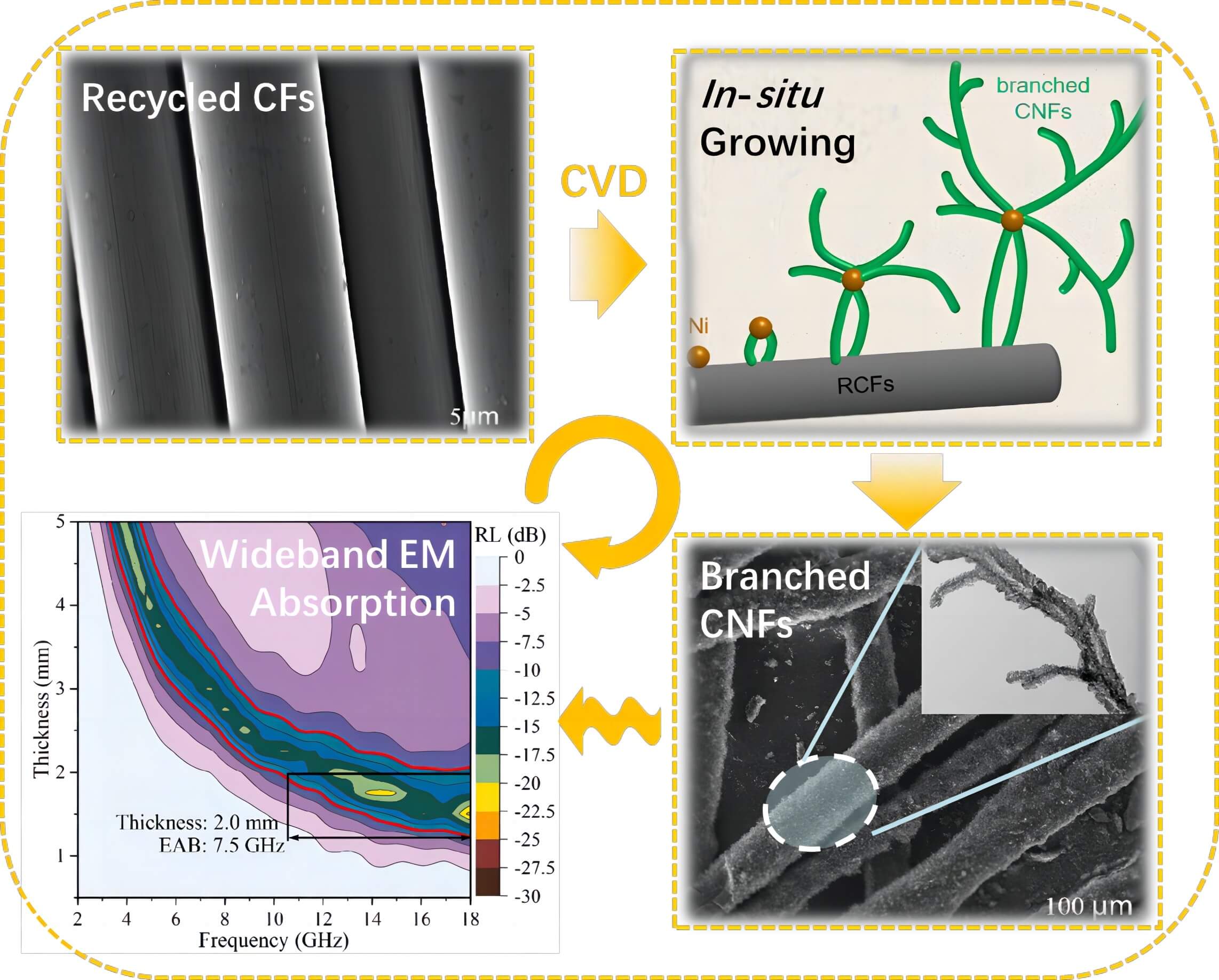
The recycling of carbon fibers and protection from unwanted microwave radiation are two important environmental issues that need to be addressed in modern society. Herein, branched carbon nanofibers (CNFs) were grown in-situ on recycled carbon fibers (RCFs) through the chemical vapor deposition method using nickel as catalysts and thiophene as aided-catalysts. The effect of thiophene on the growth morphology of CNFs was investigated. Correspondingly, branched CNFs-RCFs and straight CNFs-RCFs were respectively obtained in the presence and absence of thiophene. The microstructure and electromagnetic behaviour investigations have shown that the branched CNFs possess a typical multi-branched structure, with more defects, pores and a larger specific surface area than the straight CNFs, which lead to better impedance matching and adequate dielectric loss ability for the branched CNFs-RCFs. The reflection loss (RL) results show that the branched CNFs-RCFs exhibit an optimum RL of −23.6 dB at 1.5 mm and a best effective absorption bandwidth (EAB) of 7.5 GHz at 2.0 mm. This research provides an innovative microwave absorbing material with adequate absorbing strength and outstanding EAB, while also promoting the sustainable reuse of the RCFs resources.Graphic Abstract
Keywords
Nowadays, carbon fiber reinforced polymer (CFRP) is used in a wide range of applications such as aerospace, automotive, sports equipment, civil engineering, etc. Due to its low-density, outstanding mechanical performance, excellent fatigue and corrosion resistance properties. Nevertheless, this extensive use of CFRP has also produced a tremendous quantity of CFRP waste, creating serious waste management and environmental problems. Therefore, recycling the CFRP waste materials and putting them back on the track of a circular economy has attracted more and more attention from industrialists and researchers, especially for high-value carbon fibers [1,2]. Recycled carbon fibers (RCFs) are often reused as reinforcing phases in structural materials such as polymer and cement composites [3,4], but with a weaker strength than fresh fibers. It is also meaningful to look for applications of RCFs in functional materials with lower strength requirements [5,6].
Referring to functional materials, microwave absorption materials are urgently needed in today’s society where electronic devices are prevalent and electromagnetic pollution is a growing concern. Recently, a great deal of research has been devoted to the development of lighter, thinner, stronger and more cost-effective microwave absorption materials [7–9]. Carbon fiber is considered one of the most potentially advanced microwave absorption materials owing to its inherent properties of mechanical and electrical. However, as carbon fibers are not magnetic and have good electrical conductivity, their characteristic impedance differs significantly from that of free space, i.e., the impedance is poorly matched, which results in their interaction with microwaves being mainly reflected rather than absorbed [10]. For enhancing the microwave absorption performance, traditional approaches are to incorporate the carbon fibers with magnetic materials, for instance, Fe@carbon fibers [11], FeCo-coated carbon fibers [12], carbon fiber embedded with FeCo/CoFe2O4 [13], and FeIII-MOF-5 [14] were prepared. In this case, weight-increasing, mechanical and heat-resistance weakening, and complicated interface issues are usually inevitable, which are contrary to developments in advanced microwave absorption materials.
It is accepted that, in addition to components, micromorphology, including shapes, sizes, and pores, is another important factor affecting microwave absorption properties. Fortunately, carbon is such a mysterious and wonderful element that its nanomaterials can exist in many forms, such as carbon nanotubes (CNTs) [15], carbon nanofibers (CNFs) [16], branched CNFs [17], carbon coils [18], etc. which provide the flexibility to tailor their electromagnetic properties. Most recently, Zhang et al. [16] designed a hybrid architecture by directly growing porous carbon nanotubes on carbon fibers, the optimal reflection loss (RL) is −44.5 dB with a thickness of 2.0 mm. Singh et al. [19] synthesized a hybrid material of CNT-coated carbon fiber, and found that the composite of only 0.35 wt% CNT-coated carbon fiber filled in the epoxy matrix achieved −42.0 dB of RL and 2.7 GHz of effective absorption bandwidth (RL < −10 dB) at 2.5 mm thickness. It is believed that the bent carbon nanotubes formed hollow gaps which facilitate multiple reflections and scattering, leading to further loss of electromagnetic energy. Compared with straight carbon nanotubes/nanofibers, branched CNFs are easier to form hollow gaps between the individual nanofibers. Moreover, the branched CNFs induced by pentagons, heptagons, or other defects in the carbon lattices, might present special electronic properties and have potential applications in microwave absorption. However, as far as we know, the branched CNFs as microwave-absorbing materials have not been reported. In the present work, branched CNFs were in-situ grown on the surface of RCFs to form a hybrid of branched CNFs-RCFs, by chemical vapor deposition (CVD) method, using Ni nanoparticles as catalysts. For the selective growth of branched CNFs, thiophene as an assistant catalyst has been applied during CVD. The influence of thiophene on the morphology of CNFs, as well as the dependence of microwave absorption ability on the morphology were investigated. It is demonstrated that benefiting from the multi-branched morphology, large surface area, and porous and defective structure, the branched CNFs-RCFs exhibits excellent microwave absorption property. This research will also help to facilitate the sustainable development and advancement of RCFs resources.
The wast CRFP sheets were provided by Zhuzhou Times New Material Co., Ltd., China. Nickel nitrate and urea with a purity of analytical grade were obtained from Tianjin Kemiou Chemical Reagent Co., Ltd. Thiophene (C4H4S) with a purity of 99.0% was purchased from Tianjin Guangfu Technology Development Co., Ltd., China. Acetylene and hydrogen gas with a purity of 99.9% were supplied by Zhuzhou Hualong specialty gases Co., Ltd., China. All the chemicals were used after purchase without further purification.
2.2 Recycling Carbon Fibers from the Waste Materials of CFRP
RCFs were obtained by the pyrolysis method with two steps [20]. Firstly, the wast CFRP sheets were thermally decomposed at 750°C for 2 h under the N2 atmosphere in a quartz tube furnace. Secondly, the char on the surface of carbon fibers was oxidized at 400°C for 60 min by introducing the air gas.
2.3 Loading Ni Catalysts on the Surface of the RCFs
A simple method of urea precipitation was used to load the Ni catalysts on the surface of RCFs. Firstly, 0.02 mol nickel nitrate and 0.06 mol urea were dissolved into 200 mL deionized water to form a catalyst precursor solution. Secondly, an adequate amount of RCFs (being cut into about 2 mm) was impregnated in the catalyst precursor solution and followed by heating at 120°C for 3 h within an airtight container to precipitate Ni hydroxide. After that, these RCFs were washed, dried and finally calcined at 400°C under the N2 atmosphere for 3 h and reduced by H2 at 450°C for 1 h. Finally, Ni catalysts-coated RCFs were obtained.
The growth of CNFs was performed in a vertical CVD furnace system. First, the furnace was heated under N2 atmospheric protection at a ramp rate of 5°C/min until the growth temperature of 740 ± 5°C. Then the temperature was maintained for 60 min. Meanwhile, a gas mixture of acetylene (1.0 L/min) and hydrogen (2.0 L/min) was introduced into the reactor. Thereinto, 0.6 L/min of hydrogen was bubbled through thiophene to introduce thiophene into the CVD furnace (For comparison, experiments without thiophene and with more thiophene during the CVD process were also conducted.). Finally, the vertical furnace was cooled down naturally and CNFs-RCFs hybrid materials were obtained. The complete process of the hybrid material preparation is shown in Fig. 1.
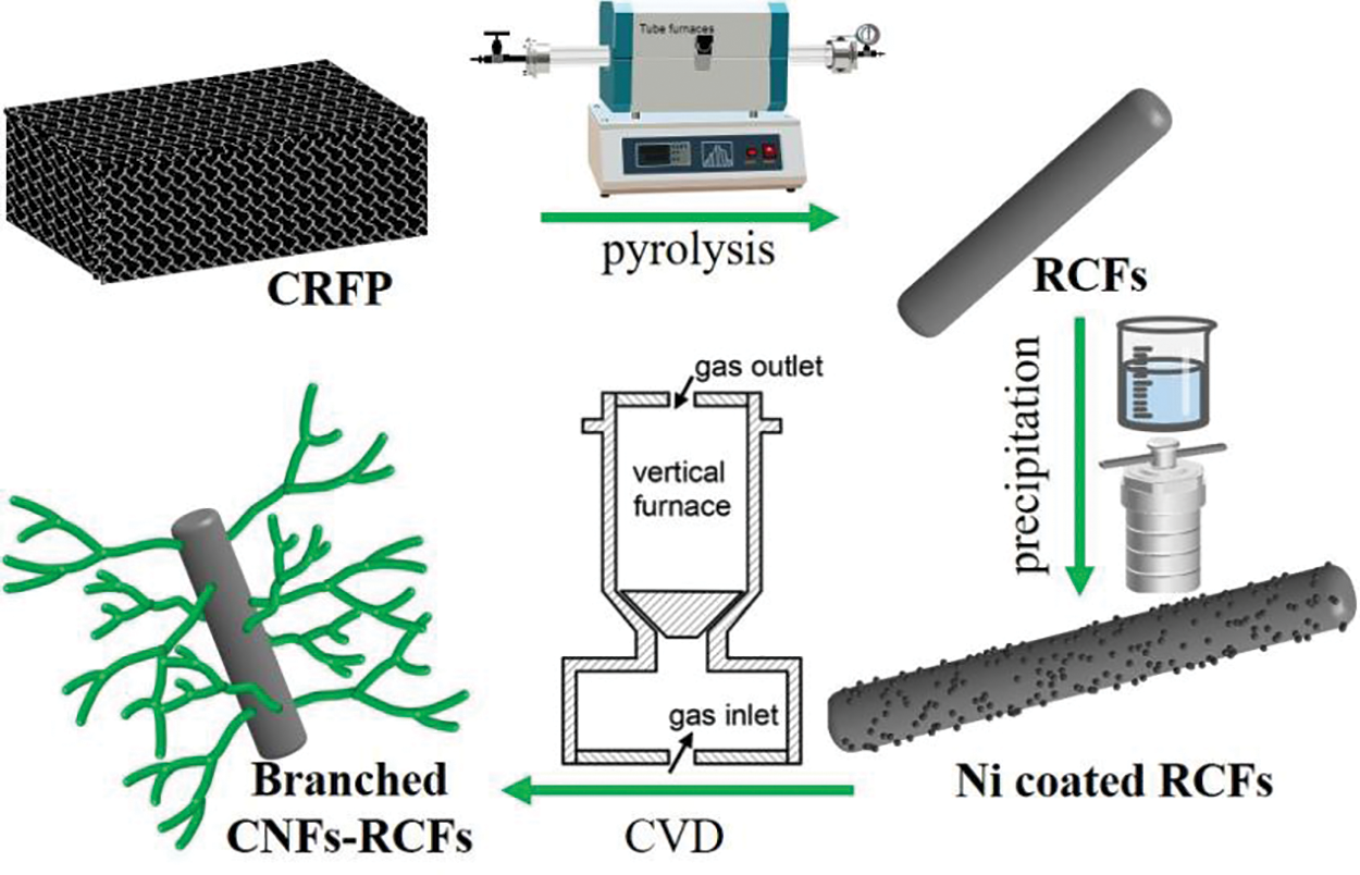
Figure 1: Schematic illustration of the material preparation process
The morphology and structure of samples were investigated by field emission scanning electron microscopy (SEM, Nova Nano230), transmission electron microscopy (TEM, Japan FEM-2100F), X-ray diffraction (XRD, D/max 2550) and Raman spectra (LabRAM ARAMIS, France HORIBA Jobin Yvon, taken with 514.5 nm incident radiation). The porosity of samples was analyzed by N2 adsorption/desorption measurements using a Quantachrome instrument (Quabrasorb SI-3MP) at 77.35 K. The electromagnetic parameters, i.e., the relative complex permittivity (
The attenuation constant (α) was calculated by the following formula [21]:
The RL values were calculated according to the transmission line theory [22], as follows:
where Zin is the input impedance of the absorber and Z0 is the nature impedance of free space, f is the frequency of the electromagnetic wave, d is the thickness of the absorber and c is the velocity of light.
3.1 Characterization of RCFs and Ni-Coated RCFs
Figs. 2a and 2b show the SEM images of the recycled carbon fibers and the Ni-coated RCFs, respectively. It can be seen that after the recycling treatment, the surface of the RCFs is smooth and clean, with very little char residue. While after coating with Ni catalysts, Ni particles with diameters of 150–300 nm are densely dispersed on the surface of RCFs. The EDS pattern (inset, Fig. 2c) shows the presence of C, Ni, and O in the Ni-coated RCFs. Compared with the Ni-coated fresh carbon fibers prepared under the same condition in our previous works, the relative intensity of the oxygen peak in the Ni-coated RCFs is higher [23], which can be ascribed to the introduction of oxygen-functional groups during the oxidation process [6]. The surface of RCFs activated by the oxygen-functional groups would facilitate the Ni particle anchoring, and the weight of RCFs increased by 2.8% after Ni coating, which is higher than that of the Ni-coated fresh carbon fibers (2.3%) [24].
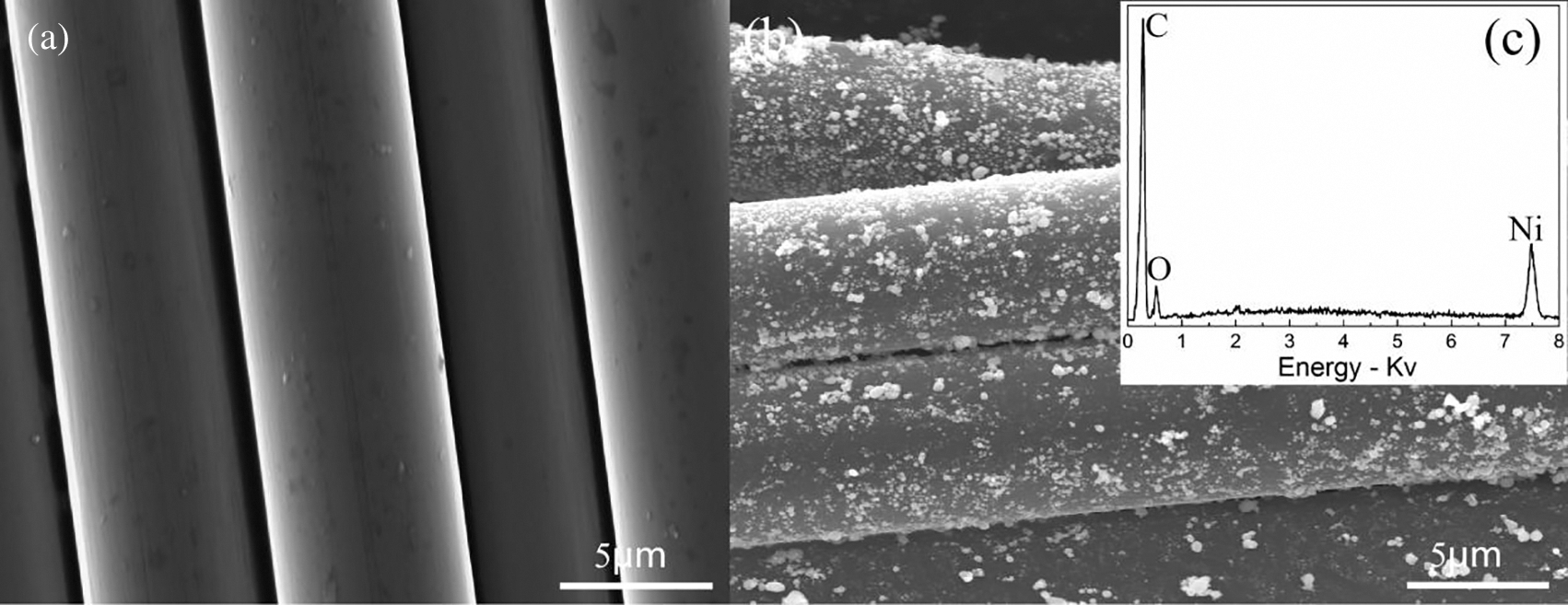
Figure 2: SEM images of (a) RCFs and (b) Ni-coated RCFs; EDS pattern of the Ni-coated RCFs (c)
3.2 Morphologies and Microstructures of CNFs Grown on RCFs
Fig. 3 shows SEM images of branched CNFs grown on the surface of RCFs for 60 min in the presence of thiophene-assisted catalysts. The general morphology of the product (Fig. 3a) indicates that a villous coating of dense CNFs on the surface of RCFs formed a hybrid fiber (named as CNFs-RCFs), and the diameter of the hybrid fibers is about ten times as large as that of the RCFs (6–7 μm). The carbon yield, which is the weight of growth CNFs divided by the weight of loading Ni catalyst, is about 320, 00% indicating that CNFs are grown fast and the efficiency of Ni catalysts is ultrahigh. Figs. 3b and 3c show enlarged views of the CNFs, they are mainly composed of multi-branched CNFs, although their diameters and branching morphologies are various. In detail, CNFs with crowded branching arms (indicated by black arrow), and CNFs with dense and small bumps on their surface like a sea cucumber (indicated by white arrow) are presented in Fig. 3b, respectively, while branched CNFs with relatively small diameters (about 50 nm) are shown in Fig. 3c. A remarkable characteristic of these branched CNFs is a large number of nano-tips on their surface, which would give them special electrical properties, such as electron hopping under strong electromagnetic fields [25]. It can also be found that numerous hollow gaps were formed between the stacking branched CNFs, which would facilitate impedance matching, multiple reflections and scattering of incident microwaves [19].
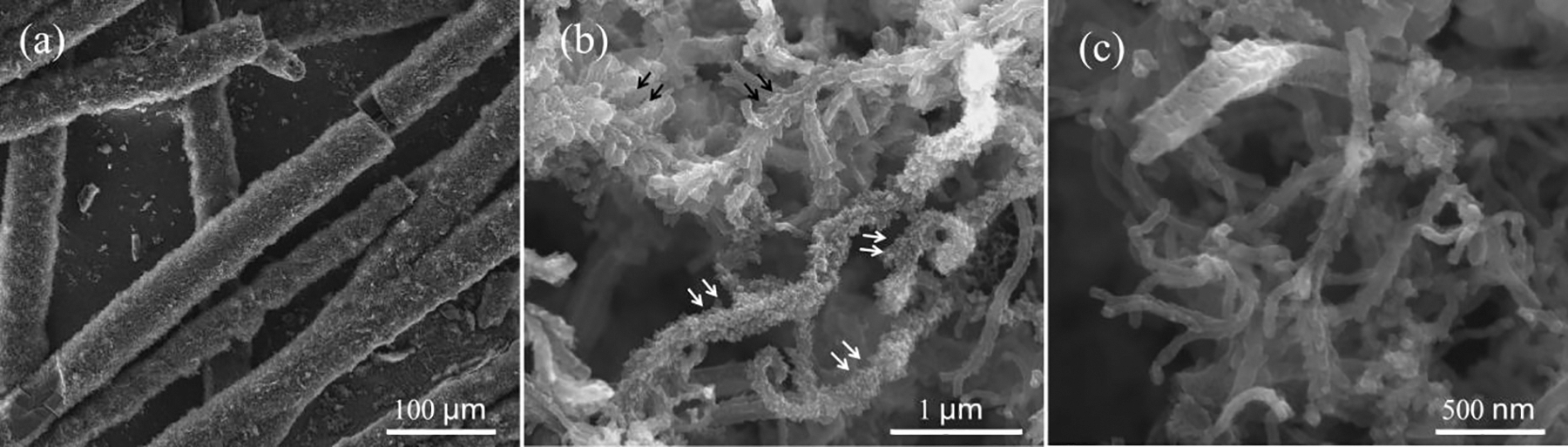
Figure 3: SEM images of branched CNFs growth on RCFs: (a) general morphology, (b) magnified image displaying the nanofibers with bulky branches (indicated by black arrow), and nanofibers with dense and small bumps like a sea cucumber (indicated by white arrow), (c) magnified image displaying the branched CNFs with a small diameter
Shown in Fig. 4 are TEM images of typical branched CNFs. Nanofibers with rough surfaces divided into multi-branches are visible in Fig. 4a. Fig. 4b corresponds to the high-resolution structure of the branched arm (the white circle zone marked in Fig. 4a), displaying a stacking of graphite layers basically parallel to the radial direction but with lots of distortion defects, especially in the area of branching interface. Fig. 4c shows the TEM image of CNFs with sea cucumber-like structures. And shown in Fig. 4d is the branched carbon nanofiber with a hollow core structure.
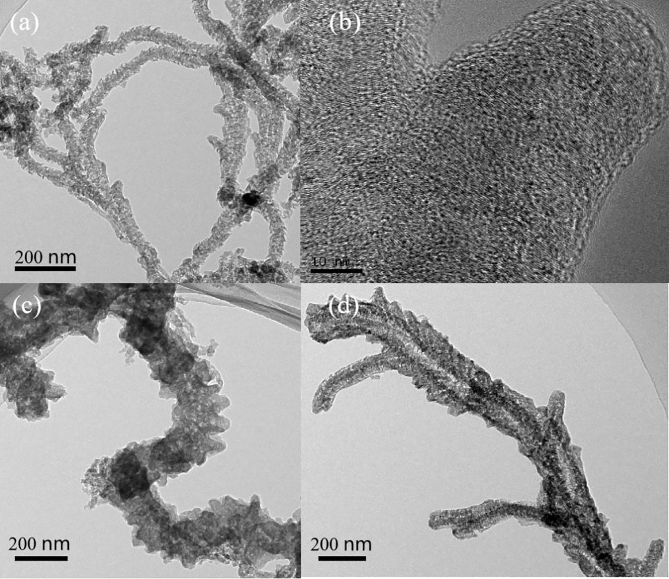
Figure 4: TEM images of typical branched CNFs: (a) single nanofibers divided into branches, (b) HRTEM of the branched arm, (c) CNFs with sea cucumber-like structure, (d) branched CNFs with hollow core structure
For comparison, SEM images of the product prepared under the CVD without thiophene are shown in Figs. 5a and 5b. Fig. 5a is the general morphology of the product, indicating CNFs grown uniformly on the surface of RCFs, while the magnified image (Fig. 5b) demonstrates that these CNFs are the straight type with diameters of 100–200 nm. The product prepared under the CVD with more thiophene (1.2 L/min of hydrogen was bubbled through thiophene to introduce thiophene into the CVD furnace) are shown in Figs. 5c, 5d and 5e. It can be seen that CNFs obtained under this condition have more irregular branches, and the HRTEM image (Fig. 5e) also shows that the orientation of their graphite layers is more disordered than the branched CNFs prepared in the appropriate thiophene case (Fig. 4b). These results indicate that thiophene as a sulfur-containing additive plays a critical role in the growth of branched CNFs.
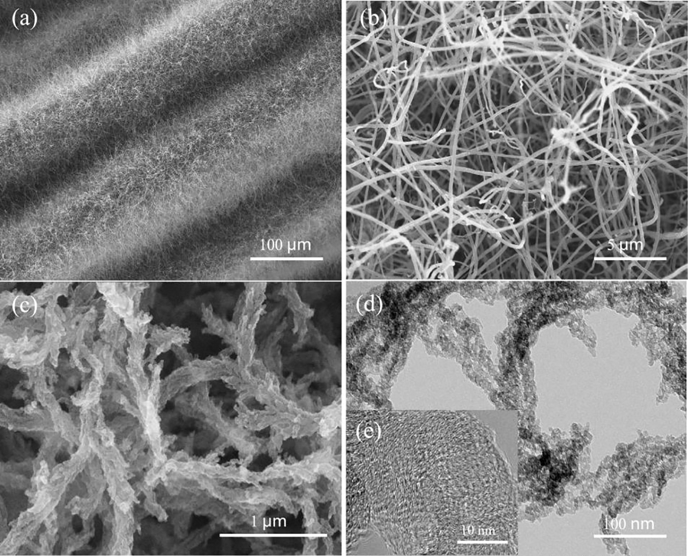
Figure 5: SEM and TEM images of products prepared under the CVD without (a, b) and with more (c, d, e) thiophene: (a) straight CNFs-RCFs, (b) enlarged view of the image (a), (c) branched CNFs, TEM (d) and HRTEM (e) images of the branched CNFs
To further understand the growth mode of branched CNFs, SEM images of their early growing stages are presented in Fig. 6. As shown in Fig. 6a (after growing 30 s) that these CNFs followed a tip growth mode, i.e., the CNFs have Ni catalyst particles at the tip and are attached to the RCFs substrate at the end. It is interesting to note that more than one CNF was grown on a single Ni catalyst particle since multiple crystalline surfaces of the Ni catalyst particle can act as growth points for the CNFs [26]. Increasing the growth time to 5 min (Fig. 6b), it is clear that 4 to 6 CNFs grew differentiated from the individual Ni catalyst particle, some of which were detached from the RCFs substrate with the ends hanging free (as shown by white arrows in Fig. 6b). The higher magnification image (Fig. 6c) shows that the surface of CNFs is very rough with a large number of pits and cracks. These defects combined with heterogeneous atomic of sulfur would be very convenient to form new growth points for the branched arms. Actually, the role of sulfur in the controlled synthesis of branched carbon nanomaterials has been widely demonstrated. Romo-Herrera et al. systematically studied the role of sulfur during branched carbon nanostructure growth and found that the sulfur not only acts on the catalyst but also can be detected in the carbon lattice at the branching point [27]. They suggested that minute amounts of sulfur are sufficient to induce the creation of heptagons and pentagons in the sp2 carbon network which promotes the formation of bumps during the carbon nanotube growth, and the bumps promote the formation of the second and third arms that eventually develop into carbon nanotube junctions [28]. In this study, the CNFs were grown at a lower temperature (740 ± 5°C) with more disorder and defects in their graphite layers. This, coupled with the help of sulfur atoms, greatly facilitated the change in the stacking angle of the graphite layers, resulting in the formation of dense bumps on the surface of CNFs, which ultimately developed into multi-branched CNFs. Based on the above analysis, a schematic illustration of the growth of branched CNFs on the surface of RCFs is shown in Fig. 6d. However, further investigation should be carried out to clarify the growth mechanism of the branched CNFs.
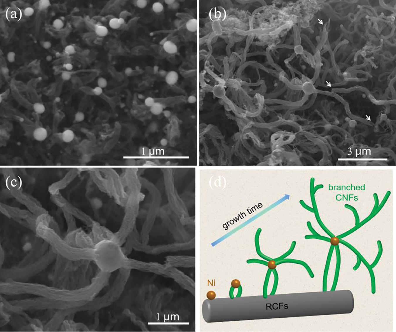
Figure 6: SEM images of CNFs growth for 30 s (a) and 5 min (b); the enlarged view of CNFs growth from the Ni catalyst particle (c); schematic illustration of the growth of branched CNFs on the RCFs (d)
Fig. 7a shows Raman spectra of the straight CNFs and branched CNFs, two characteristic peaks around 1340 and 1580 cm−1 corresponding to disordered D- and graphitic G-bands of carbon nanofibers, respectively. A strong peak of D-band and a broad peak of G-band appear in each spectrum, indicating the presence of numerous disorders and distorted defects in both straight CNFs and branched CNFs. However, the full width at half-maximum (FWHM) of branched CNFs is significantly wider than that of the straight CNFs and the ID/IG ratio (obtained from the Lorentzian fit of the peaks) of the branched CNFs is also slightly above that of the straight CNFs, suggesting that the branched CNFs have more disorder and distortion defects. Such difference can be attributed to the introduction of thiophene during the growth of branched CNFs, where the sulfur atoms from the thiophene would increase the defective degree in the carbon plane [29]. These defects can be expected to become dipole polarization centers when stimulated by alternating fields, thereby enhancing the polarization loss of incident microwaves [30,31]. The XRD patterns of straight CNFs-RCFs and branched CNFs-RCFs also demonstrate their disordered structure feature. As can be seen in Fig. 7b, both samples exhibit two broad diffraction peaks located at 2θ of 24.5o and 42.5o, corresponding to the (002) and (100) lattice planes of graphitic carbon, respectively. And very weak diffraction peaks of Ni can be found only in the straight CNFs-RCFs, indicating the Ni catalyst content in the sample is too low to be detected. Although about 2.8% of Ni catalysts were loaded on the surface of RCFs during the preparation of Ni-coated RCFs, after growing CNFs, the Ni content in the as-prepared hybrid is actually very low (less than 0.27%).
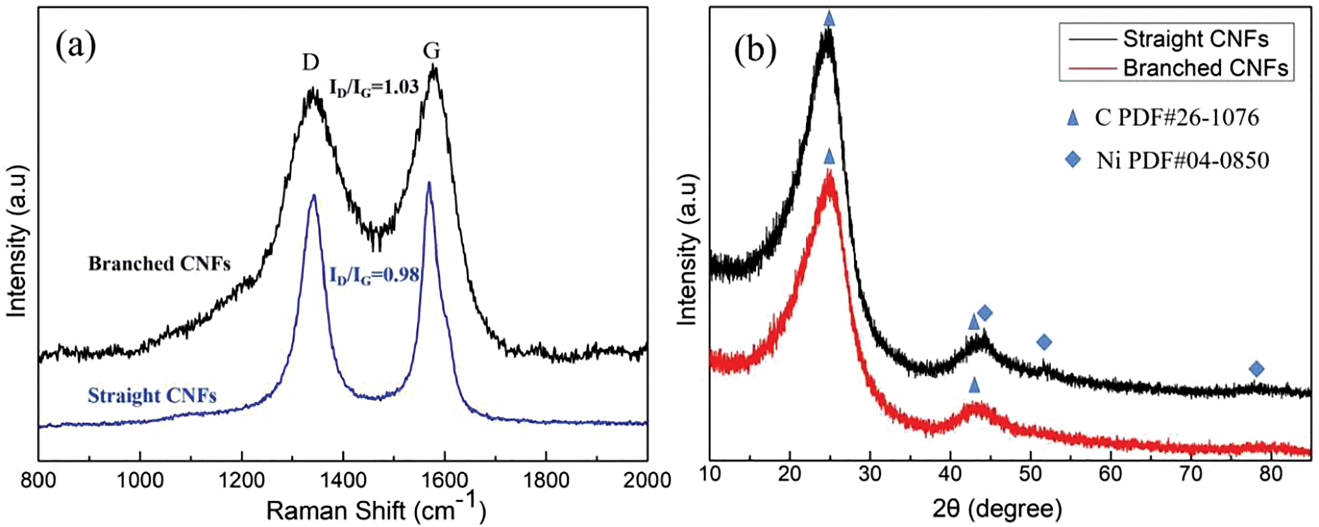
Figure 7: Raman spectra (a) and XRD (b) of the straight CNFs and branched CNFs
The nitrogen adsorption-desorption isotherms of the straight CNFs-RCFs and branched CNFs-RCFs have been shown in Fig. 8. It is found that their absorption process can be classified type IV in the IUPAC, with similar B-type hysteresis loop, indicating that the pores on the surface of the branched CNFs are mainly slit-shaped mesopores. However, the adsorption capacity of branched CNFs-RCFs is much higher than that of straight CNFs-RCFs due to the larger specific surface area. The calculated BET surface area of branched CNFs-RCFs and straight CNFs-RCFs are 104.6 and 32.3 m2/g, respectively. The inset view in Fig. 8 presents the pores distribution of the branched CNFs-RCFs (calculated by density functional theory), indicating that the branched CNFs possess primarily mesopores with sizes of 3–4 nm and some micropores with sizes about 1.5 nm. The results of the BET and pores distribution signify the rough surface of branched CNFs, which is confirmed by the above SEM and TEM analysis. It also implies that the branched CNFs-RCFs would have a strong interfacial polarisation for microwave absorption.

Figure 8: N2 adsorption/desorption isotherms of straight CNFs-RCFs and branched CNFs-RCFs. The inset represents the DFT pore-size distribution plot of branched CNFs-RCFs
3.3 Microwave Absorption Properties of the CNFs-RCFs
The electromagnetic parameters testing samples with cylindrical toroidal shape (out = 7 mm, in = 3 mm) were fabricated by uniformly dispersing 10 wt% of the CNFs-RCFs into the paraffin matrix. Among them, the sample containing the straight CNFs-RCFs is named s-1 and the sample containing the branched CNFs-RCFs is named s-2. Fig. 9 shows the frequency (2–18 GHz) dependence of complex permittivity (
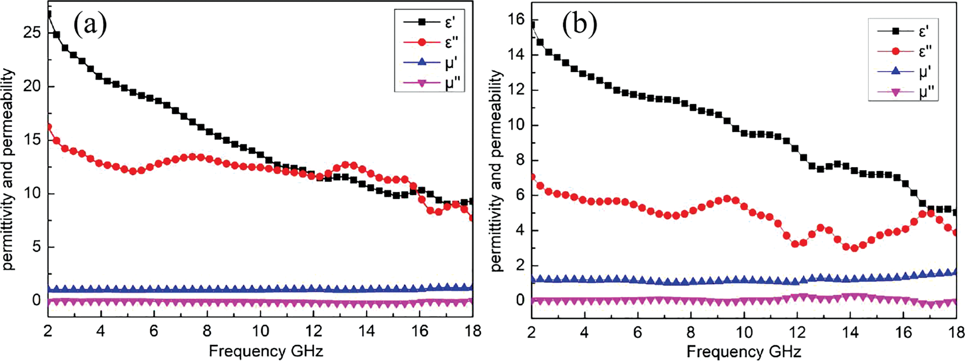
Figure 9: Frequency dependences of real and imaginary parts of complex permittivity and permeability of s-1 (a) and s-2 (b)
Fig. 10a shows the dielectric loss tangent (tanδe=ε"/ε′) for s-1 and s-2 samples in the measured frequency range (2–18 GHz), which usually be used to evaluate the attenuation capability of dielectric absorbing materials. It is observed that the tangent value of the s-1 sample gradually increases from 0.45 to 1.1 in 2–14 GHz, and then shakes down to about 0.8 in the range of 14–18 GHz. The tangent value of the s-2 sample is lower than that of the s-1 sample, indicating a weaker dielectric loss ability, which corresponds with the lower values of the real and imaginary parts of its complex permittivity. In addition, the tangent value curve of the s-2 sample has more resonant peaks than that of the s-1 sample, implying their difference in dielectric loss mechanisms. As we all know, the dielectric loss capability depends mainly on the conductive and polarization losses, and in the test frequency range the polarization loss principally consists of dipole polarization and interfacial polarization. To explain the difference in dielectric loss mechanism between the s-1 sample and the s-2 sample, the curves of ε′′ vs. ε′ are plotted (Figs. 10b and 10c), where a nearly linear trailing indicates the presence of conduction loss and a semicircle (so-called Cole-Cole semicircle) generally corresponds to a relaxation process according to the Debye theory [32]. Two obvious semicircles are observed in s-1, which could be attributed to interfacial polarization from the straight CNFs/RCFs interface and the straight CNFs/wax interface. Four semicircles can be found in s-2, indicating the increase of relaxation processes, which could correspond to interfacial polarization from the branched CNFs/RCFs interface and the branched CNFs/wax interface, as well as dipolar polarization induced by plentiful defects and slight S-doping in branched CNFs. Additionally, a long trailing that existed in s-1 suggests its strong conductive loss, however, a short trailing presented in s-2 indicates the conductive loss is weaker than that of s-1. As mentioned above, the branched CNFs have abundant defects of cracks, micropores and lattice distortions, and are more likely to form hollow gaps than that of the straight carbon nanofibers, thus it is not surprising that the s-2 sample performs weaker conductivity loss due to the poorer conductivity. The absorption coefficient (α) is a more comprehensive characterization of the attenuation ability of the absorbing materials [21]. As shown in Fig. 10d, the α values for both samples basically increase with increasing frequency, but there are some fluctuations in the higher frequency range. In the range of 2–10 GHz, the α values of sample s-1 are slightly higher than those of s-2, while between 10–16 GHz, the α values of sample s-2 are largely higher than that of s-1, indicating the better attenuating ability of s-2 in this range.
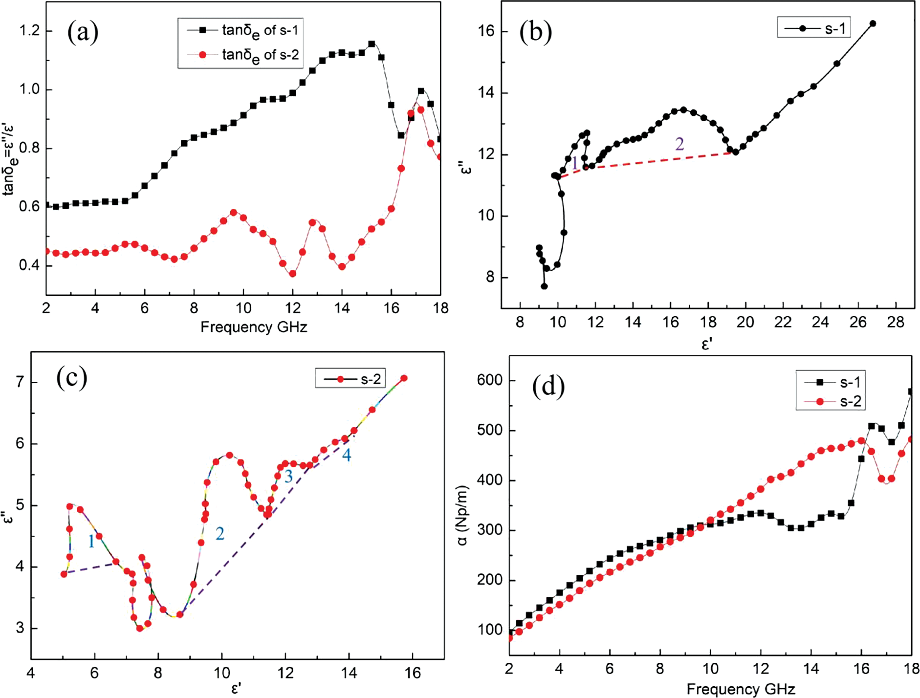
Figure 10: Dielectric loss tangent (a), ε′′-ε′ curves of s-1 (b) and s-2 (c), attenuation coefficient (d)
The calculated reflection loss (RL) curves and 3D contour maps for the two samples are shown in Figs. 11a−11d. It can be noticed that the peak of the RL value shifts towards the lower frequency with increasing thickness, which can be explained by the one-quarter wavelength theory [30]. As displayed in Figs. 11a and 11b, at a thickness of 3.5 mm, the s-1 sample has the best RL value of only −9.3 dB, and its RL value is above −10 dB for almost the full range of tested frequency and thickness. Generally, −10 dB is regarded as the threshold for the microwave absorber in practical applications, and the frequency range of RL < −10 dB is considered to be the effective absorption bandwidth (EAB). It is clear that the microwave absorption performance of the s-1 sample containing the straight CNFs-RCFs is not satisfactory. By contrast, the s-2 sample containing the branched CNFs-RCFs shows much better microwave absorption properties. Its optimal RL value reaches −23.6 dB when the thickness is only 1.5 mm, and its maximum EAB is 7.5 GHz (in the frequency range of 10.5–18 GHz) at a thickness of 2.0 mm (Figs. 11c and 11d).
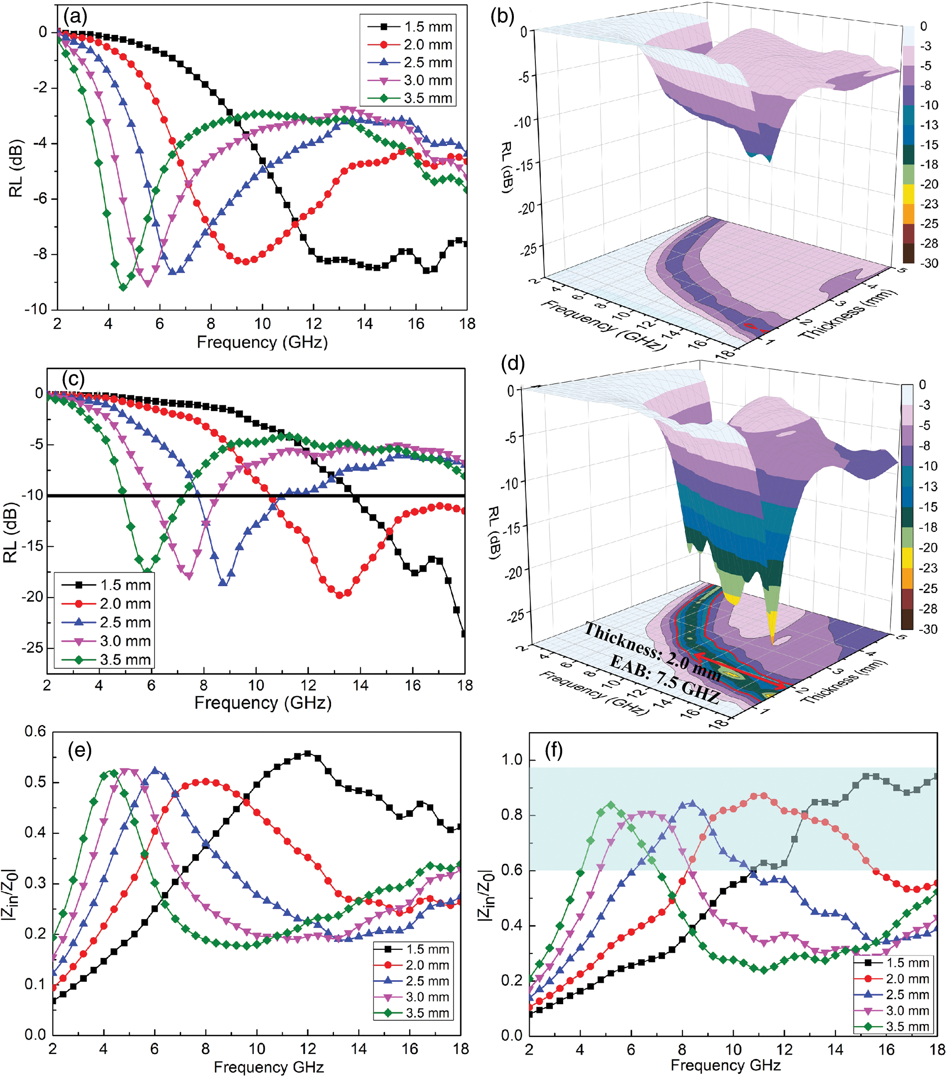
Figure 11: RL curves, 3D contour maps of s-1 (a), (b); s-2 (c), (d); and impedance matching |Zin/Z0| values of s-1 (e) and s-2 (f)
As we all know, microwave absorption materials not only need to have strong attenuation capability, but also optimal impedance matching [33]. The impedance matching can be characterized by the value of |Zin/Z0|, the closer the value is to 1, the easier the electromagnetic waves enter into the absorbers, otherwise, the electromagnetic energy will be reflected directly back from the surface. Figs. 11c and 11d display the impedance matching values of s-1 and s-2 samples, respectively. At different thicknesses, the maximum impedance matching values of the s-1 sample are all lower than 0.6, while the impedance matching value of the s-2 sample is between 0.6 and 1 for a certain frequency range, indicating a better impedance matching. In particular, when the thickness of the s-2 sample is 2.0 mm, the bandwidth of the impedance matching value that lies between 0.5 and 1 exceeds 11 GHz, which can be very advantageous for the broadband absorption and explains exactly the widest bandwidth of below −10 dB at this thickness. Therefore, the excellent microwave absorption performance of the branched CNFs-RCFs is attributed to their good impedance matching characteristic combined with appropriate dielectric loss.
On the basis of the above discussion, as illustrated in Fig. 12, the microwave absorption mechanisms of branched CNFs-RCFs can be concluded as follows: (1) the multi-scale and hollow gaps structure of the branched CNFs-RCFs allow easier access to the incident microwaves (excellent impedance matching) and cause multiple reflection and scattering of electromagnetic waves inside; (2) the interface polarization generated by the large specific surface area of the branched CNFs-RCFs and multiple heterointerfaces of branched CNFs/RCFs, branched CNFs/paraffin, etc.; (3) the conductive loss produced by electron hopping among branched nanofiber tips and electron migration in the three-dimensional conductive networks formed between stacked branched CNFs-RCFs; (4) the dipolar polarization caused by defects of abundant cracks and distortions in branched CNFs, and the dipolar polarization induced by heteroatoms, such as slight S-doping in the surface of branched CNFs.
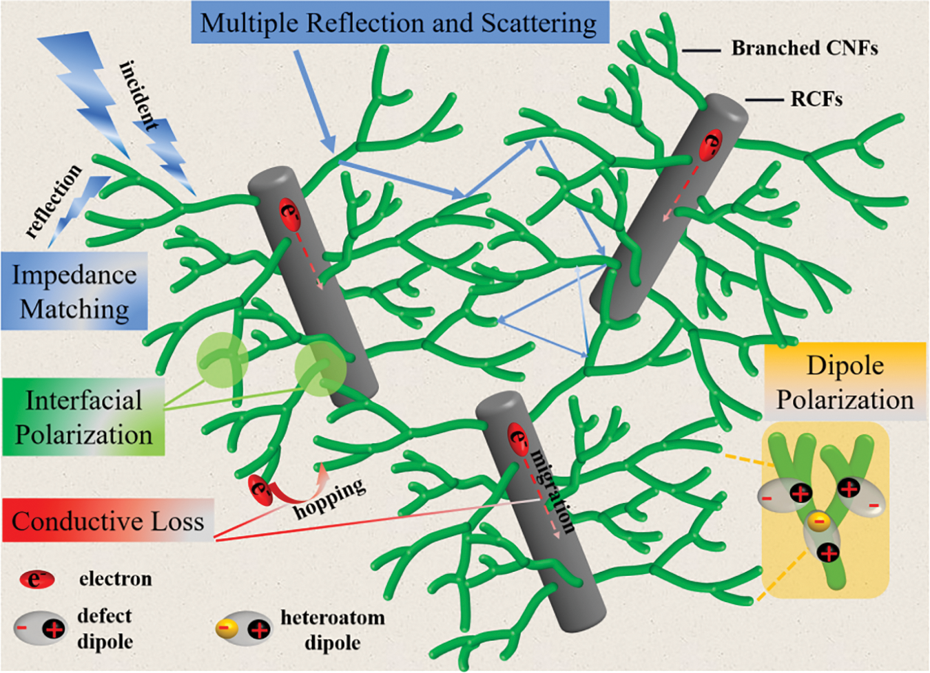
Figure 12: Schematic diagram of microwave absorption mechanisms for the branched CNFs-RCFs
Table 1 summarizes the effective absorption bandwidth of some microwave-absorbing materials reported recently. It can be seen that the s-2 sample prepared in this work shows superior wide-band absorption ability at thinner thickness compared to these reported absorbers. Therefore, the branched CNFs-RCFs (absorber in s-2 sample) is expected to be an ideal microwave-absorbing material with lightweight, wide-band absorption and good chemical stability.

In summary, branched CNFs were in situ grown on the surface of RCFs by the CVD method using Ni nanoparticles as catalysts. Thiophene as assistant catalysts play a critical role in the selective growth of branched CNFs. Without thiophene, only straight CNFs were obtained. Benefiting from the multi-branched morphology, large surface area, and porous and defective structure, the branched CNFs-RCFs possess optimal impedance matching characteristics and adequate dielectric loss ability from multiple reflection and scattering, interface polarization and dipolar polarization as well as conductive loss. Thus, the branched CNFs-RCFs exhibit an optimum RL of −23.6 dB at 1.5 mm and a maximum EAB of 7.5 GHz at 2.0 mm, which is much better than that of straight CNFs-RCFs as well as other microwave absorbers. This research provides a novel microwave absorbing material with lightweight, wide-band absorption and good chemical stability, and will contribute to the sustainable development and advancement of the RCFs resources.
Funding Statement: This work was supported by the Natural Science Foundation of Hunan Province, China (2021JJ40175), the Science Research Project of Hunan Provincial Department of Education (20C0630).
Conflicts of Interest: The authors declare that they have no conflicts of interest to report regarding the present study.
References
1. Balaji, A. B., Rudd, C., Liu, X. (2020). Recycled carbon fibers (rCF) in automobiles: Towards circular economy. Materials Circular Economy, 2(1), 1–8. https://doi.org/10.1007/s42824-020-00004-0 [Google Scholar] [CrossRef]
2. Butenegro, J. A., Bahrami, M., Abenojar, J., Martínez, M. Á. (2021). Recent progress in carbon fiber reinforced polymers recycling: A review of recycling methods and reuse of carbon fibers. Materials, 14(21), 6401. https://doi.org/10.3390/ma14216401 [Google Scholar] [PubMed] [CrossRef]
3. Li, Y. F., Li, J. Y., Ramanathan, G. K., Chang, S. M., Shen, M. Y. et al. (2021). An experimental study on mechanical behaviors of carbon fiber and microwave-assisted pyrolysis recycled carbon fiber-reinforced concrete. Sustainability, 13(12), 6829. https://doi.org/10.3390/su13126829 [Google Scholar] [CrossRef]
4. Bledzki, A. K., Seidlitz, H., Krenz, J., Goracy, K., Urbaniak, M. et al. (2020). Recycling of carbon fiber reinforced composite polymers—Review—Part 2: Recovery and application of recycled carbon fibers. Polymers, 12(12), 3003. https://doi.org/10.3390/polym12123003 [Google Scholar] [PubMed] [CrossRef]
5. May, D., Goergen, C., Friedrich, K. (2021). Multifunctionality of polymer composites based on recycled carbon fibers: A review. Advanced Industrial and Engineering Polymer Research, 4(2), 70–81. https://doi.org/10.1016/j.aiepr.2021.01.001 [Google Scholar] [CrossRef]
6. Wang, K., Chen, C., Zheng, Q., Xiong, J., Liu, H. et al. (2022). Multifunctional recycled carbon fiber-Ti3C2Tx MXene paper with superior electromagnetic interference shielding and photo/electro-thermal conversion performances. Carbon, 197, 87–97. https://doi.org/10.1016/j.carbon.2022.06.026 [Google Scholar] [CrossRef]
7. Lv, H., Yang, Z., Liu, B., Wu, G., Lou, Z. et al. (2021). A flexible electromagnetic wave-electricity harvester. Nature Communications, 12(1), 834. https://doi.org/10.1038/s41467-021-21103-9 [Google Scholar] [PubMed] [CrossRef]
8. Lv, H., Zhou, X., Wu, G., Kara, U. I., Wang, X. (2021). Engineering defects in 2D g-C3N4 for wideband, efficient electromagnetic absorption at elevated temperature. Journal of Materials Chemistry A, 9(35), 19710–19718. https://doi.org/10.1039/D1TA02785A [Google Scholar] [CrossRef]
9. Zhuo, L., Cai, Y., Shen, D., Gou, P., Wang, M. et al. (2023). Anti-oxidation polyimide-based hybrid foams assembled with bilayer coatings for efficient electromagnetic interference shielding. Chemical Engineering Journal, 451, 138808. https://doi.org/10.1016/j.cej.2022.138808 [Google Scholar] [CrossRef]
10. Ding, D., Wang, Y., Li, X., Qiang, R., Xu, P. et al. (2017). Rational design of core-shell Co@C microspheres for high-performance microwave absorption. Carbon, 111, 722–732. https://doi.org/10.1016/j.carbon.2016.10.059 [Google Scholar] [CrossRef]
11. Zhang, X., Qi, S., Zhao, Y., Wang, L., Fu, J. et al. (2020). Synthesis and microwave absorption properties of Fe@ carbon fibers. RSC Advances, 10(54), 32561–32568. https://doi.org/10.1039/D0RA03547E [Google Scholar] [PubMed] [CrossRef]
12. Wan, Y., Xiao, J., Li, C., Xiong, G., Guo, R. et al. (2016). Microwave absorption properties of FeCo-coated carbon fibers with varying morphologies. Journal of Magnetism and Magnetic Materials, 399, 252–259. https://doi.org/10.1016/j.jmmm.2015.10.006 [Google Scholar] [CrossRef]
13. Cheng, Z., Cao, Y., Wang, R., Xia, L., Ma, S. et al. (2021). Hierarchical surface engineering of carbon fiber for enhanced composites interfacial properties and microwave absorption performance. Carbon, 185, 669–680. https://doi.org/10.1016/j.carbon.2021.09.053 [Google Scholar] [CrossRef]
14. Chen, J., Zheng, J., Wang, F., Huang, Q., Ji, G. (2021). Carbon fibers embedded with FeIII-MOF-5-derived composites for enhanced microwave absorption. Carbon, 174, 509–517. https://doi.org/10.1016/j.carbon.2020.12.077 [Google Scholar] [CrossRef]
15. Han, Y., Yuan, J., Zhu, Y., Wang, Q., Li, L. et al. (2022). Implantation of WSe2 nanosheets into multi-walled carbon nanotubes for enhanced microwave absorption. Journal of Colloid and Interface Science, 609, 746–754. https://doi.org/10.1016/j.jcis.2021.11.079 [Google Scholar] [PubMed] [CrossRef]
16. Zhang, T., Xiao, B., Zhou, P., Xia, L., Wen, G. et al. (2017). Porous-carbon-nanotube decorated carbon nanofibers with effective microwave absorption properties. Nanotechnology, 28(35), 355708. https://doi.org/10.1088/1361-6528/aa7ae9 [Google Scholar] [PubMed] [CrossRef]
17. He, Z. B., Maurice, J. L., Lee, C. S., Cojocaru, C. S., Pribat, D. (2014). Growth mechanisms of carbon nanostructures with branched carbon nanofibers synthesized by plasma-enhanced chemical vapour deposition. Crystengcomm, 16(14), 2990–2995. https://doi.org/10.1039/c3ce42241k [Google Scholar] [CrossRef]
18. Li, D. W., Pan, L. J., Wu, Y. K., Peng, W. (2012). The effect of changes in synthesis temperature and acetylene supply on the morphology of carbon nanocoils. Carbon, 50(7), 2571–2580. https://doi.org/10.1016/j.carbon.2012.02.015 [Google Scholar] [CrossRef]
19. Singh, S. K., Akhtar, M. J., Kar, K. K. (2018). Hierarchical carbon nanotube-coated carbon fiber: Ultra lightweight, thin, and highly efficient microwave absorber. ACS Applied Materials & Interfaces, 10(29), 24816–24828. https://doi.org/10.1021/acsami.8b06673 [Google Scholar] [PubMed] [CrossRef]
20. Pimenta, S., Pinho, S. T. (2014). Recycling of carbon fibers. In: Handbook of recycling, pp. 269–283. Netherlands: Elsevier. [Google Scholar]
21. Gu, W., Ong, S. J. H., Shen, Y., Guo, W., Fang, Y. et al. (2022). A lightweight, elastic, and thermally insulating stealth foam with high infrared-radar compatibility. Advanced Science, 9(35), 2204165. https://doi.org/10.1002/advs.202204165 [Google Scholar] [PubMed] [CrossRef]
22. Zhu, Y., Guan, X., Yang, Z. (2021). One-pot synthesis of Carbon nanotube reinforced graphene aerogels and their applications in electromagnetic wave attenuation. Journal of Physics and Chemistry of Solids, 159, 110279. https://doi.org/10.1016/j.jpcs.2021.110279 [Google Scholar] [CrossRef]
23. Liu, L., He, P. G., Zhou, K. C., Chen, T. F. (2014). Microwave absorption properties of carbon fibers with carbon coils of different morphologies (double microcoils and single nanocoils) grown on them. Journal of Materials Science, 49(12), 4379–4386. https://doi.org/10.1007/s10853-014-8137-z [Google Scholar] [CrossRef]
24. Liu, L., Zhou, K. C., He, P. G., Chen, T. F. (2013). Synthesis and microwave absorption properties of carbon coil-carbon fiber hybrid materials. Materials Letters, 110, 76–79. https://doi.org/10.1016/j.matlet.2013.07.131 [Google Scholar] [CrossRef]
25. Cao, M., Han, C., Wang, X., Zhang, M., Zhang, Y. et al. (2018). Graphene nanohybrids: Excellent electromagnetic properties for the absorbing and shielding of electromagnetic waves. Journal of Materials Chemistry C, 6(17), 4586–4602. https://doi.org/10.1039/C7TC05869A [Google Scholar] [CrossRef]
26. Motojima, S., Chen, Q. (1999). Three-dimensional growth mechanism of cosmo-mimetic carbon microcoils obtained by chemical vapor deposition. Journal of Applied Physics, 85(7), 3919–3921. https://doi.org/10.1063/1.369765 [Google Scholar] [CrossRef]
27. Romo-Herrera, J. M., Cullen, D. A., Cruz-Silva, E., Ramirez, D., Sumpter, B. G. et al. (2009). The role of sulfur in the synthesis of novel carbon morphologies: From covalent Y-junctions to sea-urchin-like structures. Advanced Functional Materials, 19(8), 1193–1199. https://doi.org/10.1002/adfm.200800931 [Google Scholar] [CrossRef]
28. Romo-Herrera, J. M., Sumpter, B. G., Cullen, D. A., Terrones, H., Cruz-Silva, E. et al. (2008). An atomistic branching mechanism for carbon nanotubes: Sulfur as the triggering agent. Angewandte Chemie International Edition, 47(16), 2948–2953. https://doi.org/10.1002/(ISSN)1521-3773 [Google Scholar] [CrossRef]
29. Fan, H., Wang, T., Gong, H., Jiang, C., Sun, Z. et al. (2021). Heteroatom sulfur-induced defect engineering in carbon nanotubes: Enhanced electrocatalytic activity of oxygen reduction reaction. Carbon, 180, 31–40. https://doi.org/10.1016/j.carbon.2021.04.072 [Google Scholar] [CrossRef]
30. Yin, P., Wu, G., Tang, Y., Liu, S., Zhang, Y. et al. (2022). Structure regulation in N-doping biconical carbon frame decorated with CoFe2O4 and (Fe,Ni) for broadband microwave absorption. Chemical Engineering Journal, 446, 136975. [Google Scholar]
31. Liu, J., Zhang, L., Zang, D., Wu, H. (2021). A competitive reaction strategy toward binary metal sulfides for tailoring electromagnetic wave absorption. Advanced Functional Materials, 31(45), 2105018. https://doi.org/10.1002/adfm.202105018 [Google Scholar] [CrossRef]
32. Sun, X., Wang, Z., Wang, S., Ning, Y., Yang, M. et al. (2021). Ultrabroad-band and low-frequency microwave absorption based on activated waxberry metamaterial. Chemical Engineering Journal, 422, 130142. https://doi.org/10.1016/j.cej.2021.130142 [Google Scholar] [CrossRef]
33. Guan, X., Yang, Z., Zhou, M., Yang, L., Peymanfar, R. et al. (2022). 2D MXene nanomaterials: Synthesis, mechanism, and multifunctional applications in microwave absorption. Small Structures, 3(10), 2200102. https://doi.org/10.1002/sstr.202200102 [Google Scholar] [CrossRef]
34. Wu, R., Yang, Z., Fu, M., Zhou, K. (2016). In-situ growth of SiC nanowire arrays on carbon fibers and their microwave absorption properties. Journal of Alloys and Compounds, 687, 833–838. https://doi.org/10.1016/j.jallcom.2016.06.106 [Google Scholar] [CrossRef]
35. Guo, R., Su, D., Chen, F., Cheng, Y., Wang, X. et al. (2022). Hollow beaded Fe3C/N-doped carbon fibers toward broadband microwave absorption. ACS Applied Materials & Interfaces, 14(2), 3084–3094. https://doi.org/10.1021/acsami.1c21272 [Google Scholar] [PubMed] [CrossRef]
36. Wu, F., Liu, Z., Xiu, T., Zhu, B., Khan, I. et al. (2021). Fabrication of ultralight helical porous carbon fibers with CNTs-confined Ni nanoparticles for enhanced microwave absorption. Composites Part B: Engineering, 215, 108814. https://doi.org/10.1016/j.compositesb.2021.108814 [Google Scholar] [CrossRef]
37. Zheng, S., Zeng, Z., Qiao, J., Liu, Y., Liu, J. (2022). Facile preparation of C/MnO/Co nanocomposite fibers for high-performance microwave absorption. Composites Part A: Applied Science and Manufacturing, 155, 106814. https://doi.org/10.1016/j.compositesa.2022.106814 [Google Scholar] [CrossRef]
38. Wang, S., Wang, Y., Sun, C., Qi, S., Wang, B. et al. (2023). Multifunctional carbon nanofibers coated Co-Zn alloy nanoparticles composite for efficient energy conversion and microwave absorption. Journal of Alloys and Compounds, 932, 167458. https://doi.org/10.1016/j.jallcom.2022.167458 [Google Scholar] [CrossRef]
Cite This Article
 Copyright © 2023 The Author(s). Published by Tech Science Press.
This work is licensed under a Creative Commons Attribution 4.0 International License , which permits unrestricted use, distribution, and reproduction in any medium, provided the original work is properly cited.
 Downloads
 Citation Tools