
 Open Access
ARTICLE

CFD Study on Hemodynamic Characteristics of Inferior Vena Cava Filter Affected by Blood Vessel Diameter
1 School of Energy and Power Engineering, Shandong University, Jinan, 250061, China
2 Department of Ultrasound, Jinan Central Hospital, Jinan, 250000, China
3 The First Affiliated Hospital of Chongqing Medical University, Chongqing, 400042, China
4 School of Aeronautic Science and Engineering, Beihang University (BUAA), Beijing, 100191, China
* Corresponding Authors: Jingying Wang. Email: ; Wen Huang. Email:
Molecular & Cellular Biomechanics 2023, 20(2), 81-94. https://doi.org/10.32604/mcb.2023.044445
Received 30 July 2023; Accepted 27 September 2023; Issue published 01 November 2023
 View Full Text
 Download PDF
Abstract
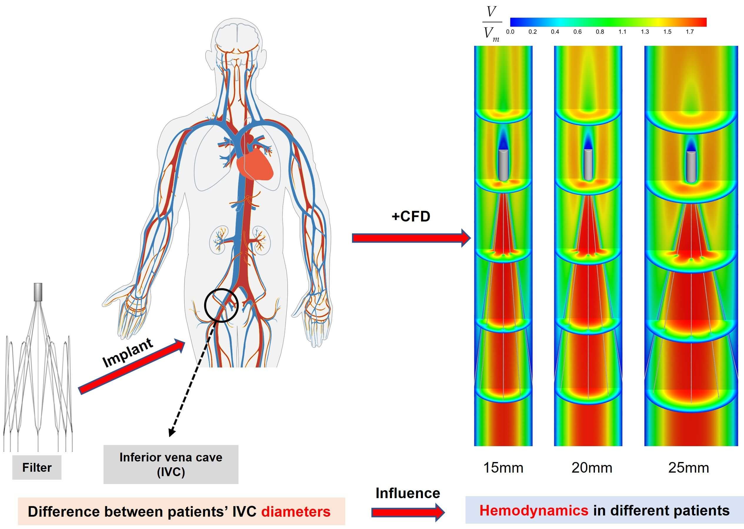
Pulmonary embolism (PE), caused by deep venous thrombosis (DVT), is a disease with high morbidity and mortality. Implantation of inferior vena cava filters is an important method for the clinical prevention of PE. The hemodynamic characteristics of filters implanted in the inferior vena cava (IVC) have a significant impact on their performance. However, IVC diameters vary among patients. This may have a direct impact on the hemodynamic properties of the filter. At present, there is no research on this kind of problem to be investigated. In this paper, the hemodynamic properties of the VenaTech convertible filter were simulated in three different IVC models of 15, 20 and 25 mm diameters, using computational fluid dynamics (CFD) as a control variable (only the IVC diameter is varied). The results showed that the diameter has a significant impact on the hemodynamic characteristics after filter implantation. The IVC diameter has a great influence on the stagnation zone of the blood flow, the maximum wall shear stress (WSS) on the upstream side along the filter wire, and the flow resistance. The case of 15 mm diameter was the most prone to thrombus formation downstream of the filter head in the IVC, but the larger WSS on the upstream along the filter wire may facilitate thrombus lysis. Therefore, the change in vessel diameter should be considered when performing filter implantation for patients.Graphic Abstract
Keywords
Venous thromboembolism (VTE), which presents as deep vein thrombosis (DVT) or pulmonary embolism (PE), is an extremely common vascular disease that can occur alone or as a complication of other diseases [1,2]. DVT and PE are in essence manifestations of the same disease in different locations and stages [3]. After myocardial infarction and stroke, PE is the third most frequent life-threatening cardiovascular disease [4]. PE is characterized by blood flow restriction in the pulmonary arteries, which usually comes on by thrombus in the inferior vena cava (IVC) [5].
The incidence of PE is high. In the United States, the number of new cases is about 300,000–600,000 per year, with about 60,000–100,000 deaths due to it [6]. The main therapeutic measure for PE is anticoagulation [7–9]. When anticoagulation is contraindicated or ineffective in patients with PE, implantation of an inferior vena cava filter (IVCF) in their IVC has become an effective means of preventing PE [10–12].
Filters have been widely used in clinical practice for more than 50 years now [13], and are mainly categorized into permanent and temporary types from a clinical use perspective [14]. Temporary filters have a lower incidence of adverse events than permanent filters [15]. The VenaTech Convertible Filter (B. Braun, Melsungen, Germany) is a commonly used temporary IVCF, which is a modification of the permanent VenaTech LP filter [8]. The VenaTech is a typical umbrella-shaped filter consisting of a head, eight filter wires and eight stabilizers, as shown in Fig. 1. The VenaTech filter is an IVCF with more flexible time limit for preventing PE, simpler conversion operation and positive effect, and is suitable for use in IVC diameters of up to 28 mm [13,16,17]. Therefore, the VenaTech filter is the most commonly used, and was chosen as the subject of this study.
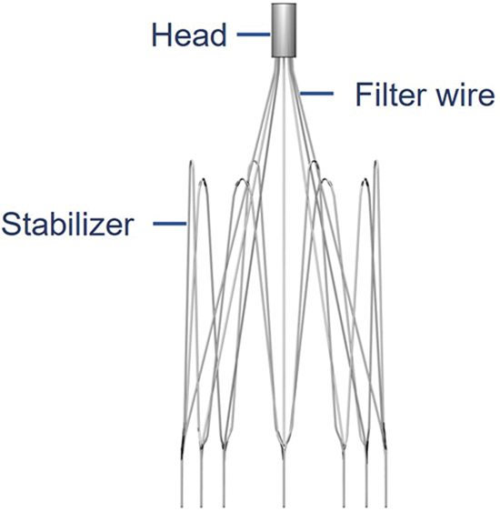
Figure 1: The VenaTech convertible filter model
After the filter is implanted, it will have a great impact on the hemodynamics in the IVC, and can even affect its therapeutic effect. Given the adverse events related to the implantation of IVCFs, the evaluation of filters is critical. Due to technical and ethical limitations, vivo studies have been limited to animals [18,19], and these studies have allowed the feasibility and efficacy of filters to be assessed, advancing the progress of filter research. However, in vivo and in vitro experiments are costly, experimental cycles are long, and animal models do not truly reflect the flow patterns within the human vasculature. In recent years, computational fluid dynamics (CFD) techniques have improved our understanding of the hemodynamics in the vasculature as a complementary tool, allowing an increasingly rich presentation of the hemodynamic properties in the IVC after filter implantation. Calculations in previous studies have shown that the stagnation zone downstream of the filter head may be a potential factor in thrombosis [20]; appropriately high WSS on the filter surface can help dissolve larger clots [20,21]. CFD also calculated the resistance to flow exerted by blood flow on the filter, which not only reflected the force of the filter in obstructing blood flow, but also balanced it with the combined force exerted by the filter on the IVC [22].
Currently, the majority of hemodynamic analyses of filter implantation in the IVC using CFD methods have been performed using a single IVC diameter. Singer et al. investigated the hemodynamic effect of Celect filter tilt on conditions of 23 mm diameter IVC [23]; Stewart et al. studied under the conditions of 20 mm diameter and compared the effect of thrombus on blood flow after implantation of three different filters in the IVC [20]. However, in clinical practice, the diameter of the IVC in different patients has significant differences [24], and the trapping rate of thrombus and the safety of the filter in the IVC of different diameters are changed [25]. The ability of IVCFs to capture thrombus is reduced when the diameter is greater than 28 mm [13]; the IVC diameter may be a potential factor influencing filter migration, thus affecting the safety of the filter after implantation in the patient [26]. Dowell et al. modeled the Celect filter under different IVC diameter conditions and investigated the effect of IVC diameter on the deformation of the Celect filter and the risk of subsequent IVC perforation using finite element analysis, which showed that the filter was more likely to deform and generate greater normal support and combined forces within the smaller diameter IVC, with a greater risk of IVC perforation [25]. However, this study did not analyze the flow field after filter implantation at different vessel diameters. When designing an IVCF, several factors need to be considered, including the geometry and hemodynamic characteristics of the filter after implantation in different human bodies [10,23,27]. The flow state of the blood flow after the filter is implanted into the IVC of different diameters not only affects the patency of the IVC blood flow, but also determines the capture rate of the filter for thrombus [27]. Therefore, exploring the hemodynamic characteristics of the filter in the IVC of different diameters can provide theoretical and technical references for the clinical use of the filter.
This paper aimed to assess the effect of IVC diameter variation on the hemodynamic properties of IVCF using CFD modeling. Computer models of the VenaTech convertible filter implanted in three different IVC diameters were constructed for comparative studies. Blood flow around the filter was simulated in Fluent (ANSYS, Inc., Canonsburg, PA, USA) for three different IVC diameters and the distribution of velocity and WSS and the flow resistance of the filter to blood flow in the different IVC diameters were discussed. The effect of IVC diameter variation on the blood flow field around the filter was discussed in depth by comparing the CFD results under three different diameter conditions.
A study of IVC geometry in 65 patients implanted with an IVCF showed that the patients’ IVC diameter ranged from 13 to 30 mm, with a mean diameter of 20 mm [24]. Therefore, in this paper, three models with 15, 20 and 25 mm diameters of the IVC implanted with VenaTech convertible filters were studied.
This study focused on the effect of vessel diameter variation on filter hemodynamics, temporarily ignoring some complex physiological factors, such as iliac and renal veins, and the IVC contractile deformation [28]. It was assumed that the IVC was a rigid straight tube with uniform wall thickness and a circular cross-section [20,29,30]. The filter was implanted normally into the IVC without considering undesirable conditions such as tilting and displacement of the filter. After implantation of the VenaTech filter into the IVC, the stabilizers of the filter are completely embedded in the wall of the IVC [16], so the stabilizers were ignored in the creation of the filter model. To achieve adequate development of blood flow in the IVC and to avoid boundary effects, flow extensions were added before and after the segment of the tube containing the filter, which was approximately 20 times the length of the IVC diameter. The VenaTech convertible filter was placed in a straight circular tube of different diameters, and detailed dimensions were obtained by projection measurements of the filter after implantation into the tube. The filter was modeled in three cases. x, y and z axes were oriented as shown in Fig. 2, with the z-axis set at the center of the IVC longitudinal section and the origin of the coordinates at the center of the filter head bottom. The grid refinement study was performed in our previous research [29] by analyzing in detail the flow properties of the 20 mm diameter case. The total number of nodes for this grid setup condition was approximately 2,410,000. The grids of the 15 and 25 mm cases were also validated using the same method.
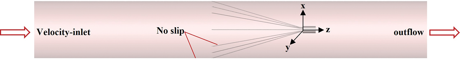
Figure 2: Filter in an inferior vena cava (IVC) model and boundary conditions
2.2 Numerical Methods and Boundary Conditions
Blood has the property of shear thinning and is a non-Newtonian fluid. Previous studies have shown that Newtonian models underestimate the predicted values of WSS when applied to blood flow and do not accurately describe the blood rheological properties of blood [31]. In contrast, the Carreau non-Newtonian model has been shown to accurately describe blood flow in humans [22,32] and is now widely used in the simulation of blood flow in the IVC. Therefore, in this paper, the Carreau model was chosen to describe the flow rheological properties of blood with the following expressions [22,33,34]:
In the above equation, μ is the blood viscosity; γ is the local shear rate; λ is the time constant with a value of 3.313 s; n is the power exponent with a value of 0.3568; μ0 is the zero shear viscosity with a value of 0.056 Pa⋅s; μ is the infinite shear viscosity with a value of 0.00345 Pa⋅s.
Compared to arteries, clinical observations show less pulsatility and pressure of IVC blood flow [10], therefore, the flow in the IVC was assumed to be constant flow [29,30] and the corresponding governing equation was the three-dimensional constant viscous incompressible Navier-Stokes equation of the following form [10,35]:
where “
where “
The setting of boundary conditions in numerical simulation directly affects the accuracy of simulation results. In this paper, the boundary conditions were set as shown in Fig. 2, one end of the IVC was used as the inlet of blood flow, and the velocity-inlet boundary condition was used; the other end was the outlet of blood flow, and the outflow boundary condition was used; both the IVC wall surface and the filter surface were used with no-slip boundary conditions. Referring to Cheng et al.’s measurements of the IVC inlet flow in 11 healthy subjects at rest [36], the IVC inlet flow for all three diameter cases was set to the mean of the measurements (1.2 L/min). The mean IVC inlet flow rates were calculated to be 0.113, 0.063, and 0.0407 m/s for 15, 20, and 25 mm diameters, respectively.
The Reynolds number was used to determine the flow state of the blood in the IVC, and the expression is as follows:
where u is the mean blood velocity; D is the IVC diameter; and
According to the Newtonian model, taking the average viscosity of blood as 0.0035 Pa⋅s [20,26], the initially calculated Reynolds numbers in the three cases were 513, 381 and 308, respectively, which were much lower than the Reynolds number of laminar to turbulent transition [22]. Since the Reynolds number calculated by the non-Newtonian model is much smaller than the Newtonian model, it can be further judged that the blood flow in the inferior vena cava is laminar.
Despite using the suitable mesh, experimental validation of the simulation results is still needed before the formal conduct of the study to obtain simulation data that more closely matches the real blood flow [37]. However, there is a lack of reliable clinical and experimental data to validate CFD results. Therefore, in this study, in vitro measurements of the TrapEase filter in a rigid, homogeneous circular tubular IVC model derived from the study of Leask et al. were used to validate the accuracy of the numerical simulations in this paper [27]. The reliability of the CFD method used in this paper has been confirmed by our previous studies [30]. The results showed that the simulated data were in high agreement with the experimental data, with an overall average deviation within 15%. Therefore, the CFD calculation method used in this paper was able to reliably reproduce the laminar flow of blood in a homogeneous straight circular tube.
Figs. 3 and 4 show the flow field distribution in the IVC for the three vessel diameters with velocities normalized by the mean flow velocity. Overall, the velocity distribution characteristics were basically the same for the three IVC diameter cases. In the conical region surrounded by the filter wires, there was a more obvious high-speed region, which was called the “acceleration region” in this paper. Due to the obstructive effect of the wires, the blood flow in all three diameters showed a clear “bifurcation” when flowing through the wires, and Fig. 3b only shows the flow in the cross-axis section of the 15 mm diameter IVC. Downstream of the filter head, there was a zone of almost zero blood flow velocity, as shown in Fig. 4, which extended in blue from the downstream of the filter head and was referred to as the “stagnation zone”. Fig. 4 shows an example of reflow in a 15 mm diameter IVC, showing the combined presence of a reflow zone and a stagnant zone downstream of the IVC filter head for all three diameter cases.
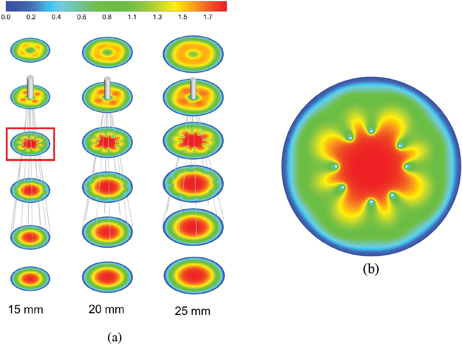
Figure 3: The velocity distribution in the cross-section, all velocities were normalized by mean flow speed, (a) shows the overall distribution at the three diameters IVC, (b) shows the details of the velocity distribution of 15 mm IVC blood flow influenced by the filter
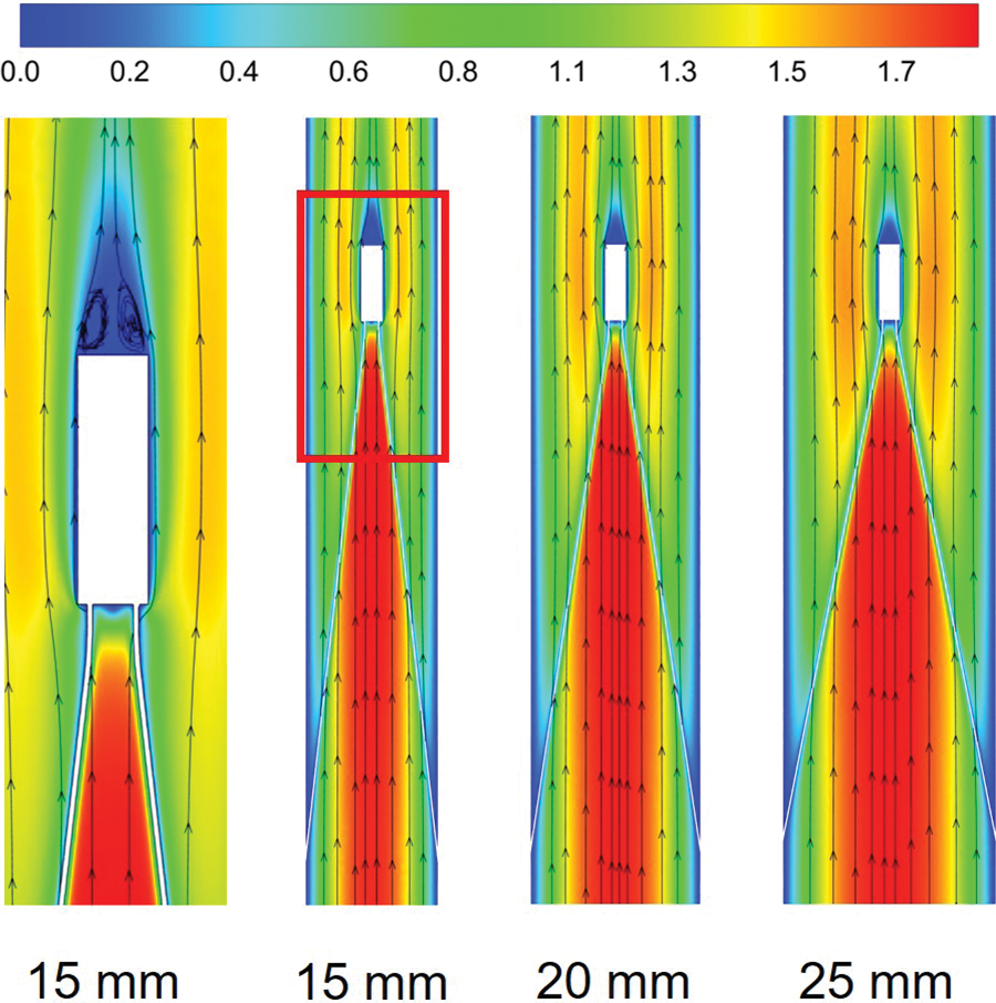
Figure 4: The velocity distribution of the long-axis section, all velocities were normalized by mean flow speed
Fig. 5 further shows the acceleration and stagnation zones in the centerline of the IVC after filter implantation, also normalized by the mean flow speed and compared to the IVC situation without filter implantation (IVC-only). The results showed that the smaller the IVC diameter, the greater the intensity of the acceleration zone, and the velocity in the accelerated zone of 15 mm diameter IVC remained maximum after normalization. Define the distance downstream from the central axis of the IVC where the blood flow velocity is higher than the IVC-only velocity of the corresponding vessel diameter as the length of the acceleration zone. The length of the acceleration zone was almost the same for all three vessel diameters of the IVC, using IVC-only as the reference. However, there were significant differences in the stagnation zone under the three diameters. Similarly, the length of the stagnation zone was defined as the distance where the velocity was lower than the IVC-only velocity. Fig. 5 shows that the smaller the diameter, the longer the length of the stagnation zone. 15 mm diameter IVC stagnation zone length was approximately 20 times its diameter, which was significantly greater than the values for 20 and 25 mm diameter. 20 and 25 mm diameter IVC stagnation zones were approximately 10 and 6 times their corresponding diameters. After the velocity was normalized, the lowest flow velocity was found in the 15 mm diameter IVC stagnation zone and the highest in the 25 mm diameter IVC stagnation zone between the downstream side of the filter head and z = 0.10 m. Therefore, the stagnation phenomenon was most pronounced in the 15 mm diameter IVC.
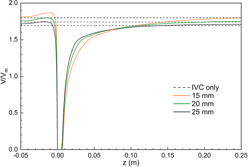
Figure 5: Distribution of central axis flow velocity in different diameters IVC, all normalized by mean velocity
The WSS distributions on the filter surface under different vessel diameters are shown in Figs. 6 and 7, all of which were normalized by the mean WSS of the corresponding diameter of the IVC-only. The form of WSS distribution on the filter surface under the three diameters was almost the same. The WSS on the upstream side along the filter wire was much higher than that on the downstream side; the WSS on the upstream and downstream sides of the filter wires both increased and reached a peak and then gradually decreased near the filter head. Fig. 7 shows that the WSS of the downstream side along the filter wire was the largest for the 25 mm diameter IVC and the smallest for the 15 mm diameter IVC. The downstream peak of WSS was almost the same for the three diameters cases, which was about 8 times the average WSS of the corresponding IVC-only diameter.
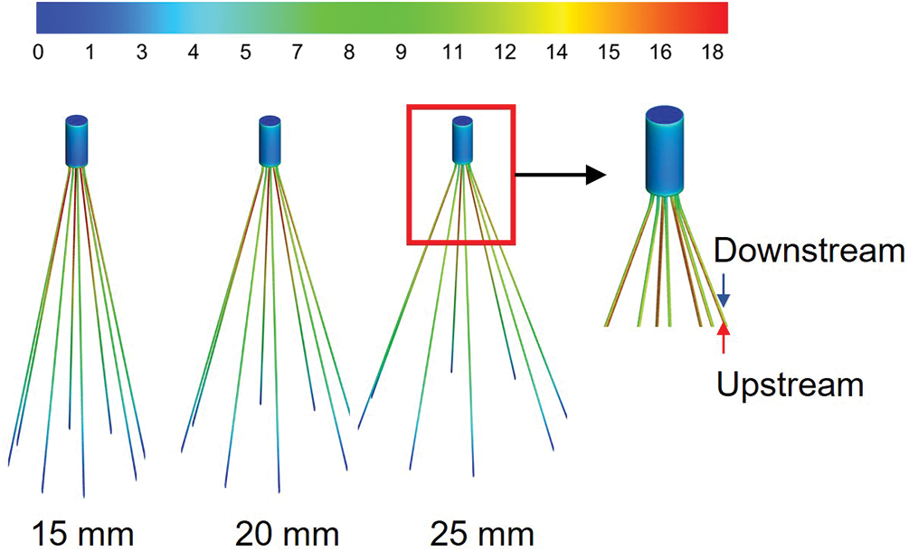
Figure 6: The WSS distribution of filters with different diameters was normalized by the average WSS of the IVC without filters implanted (IVC-only) in the corresponding diameters
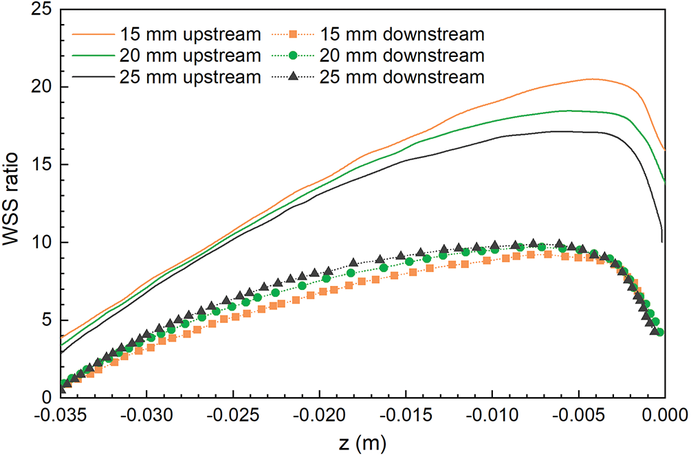
Figure 7: The WSS distribution of the filters under different IVC diameters was normalized by the mean WSS of the IVC-only in the corresponding diameters
However, the effect of diameter on the WSS of the upstream side along the filter wire was more obvious than that on the downstream side (Fig. 7). As the diameter increased, the upstream WSS decreased gradually. The upstream WSS peak at different cases was different, and the peak of upstream WSS at 15 mm IVC diameter was the largest, almost 20 times the average WSS at 15 mm IVC-only. The upstream WSS peak at 20 and 25 mm IVC diameters were 18 times and 17 times of the average WSS at the corresponding IVC-only, respectively.
Fig. 8 shows the distribution of WSS in the IVC of different diameters, all of which were normalized by the mean WSS of the corresponding IVC-only diameters. The WSS in the area of contact between the filter wires and the IVC was lower than that of IVC-only at all three tube diameters, and the decrease in WSS was most obvious at 15 mm diameter, and the change in WSS was more pronounced as the IVC diameter decreased.
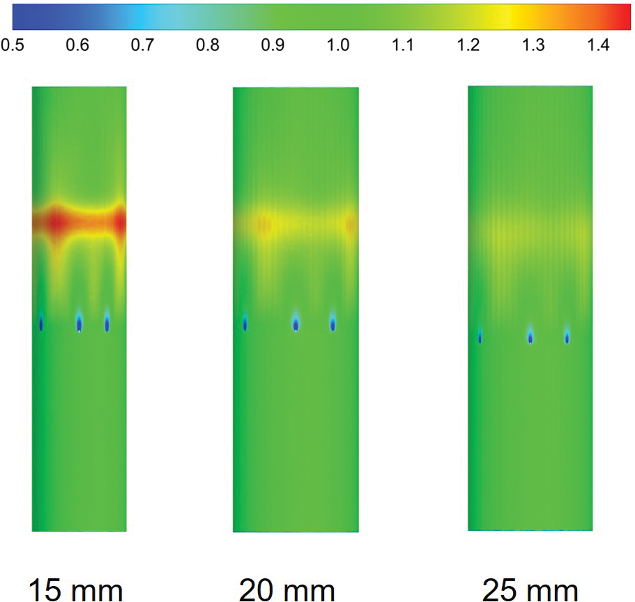
Figure 8: IVC wall WSS distribution with different diameters was normalized based on the average WSS of the IVC-only in the corresponding diameters
Due to the presence of the filter, blood flow exerts a force on the filter surface. The flow resistance Fd exerted by the blood flow on the filter includes differential pressure resistance Fp and viscous resistance Ff. Fig. 9 shows the forces exerted by the blood flow on the filter. The ratio of pressure difference resistance to total resistance was less than 10% for all three cases. The total flow resistance was mainly caused by viscous resistance, and the pressure force had little effect on the total flow resistance. With the increase in diameter, the total flow resistance, pressure resistance and viscous resistance gradually decreased, in which the pressure resistance had the smallest variation, varying from 3 to 9 dyne. 15 mm diameter IVC flow resistance and viscous resistance were significantly larger than 20 and 25 mm diameter values, almost 2 to 3 times of the 15 and 25 mm diameter cases flow resistance and viscous resistance.
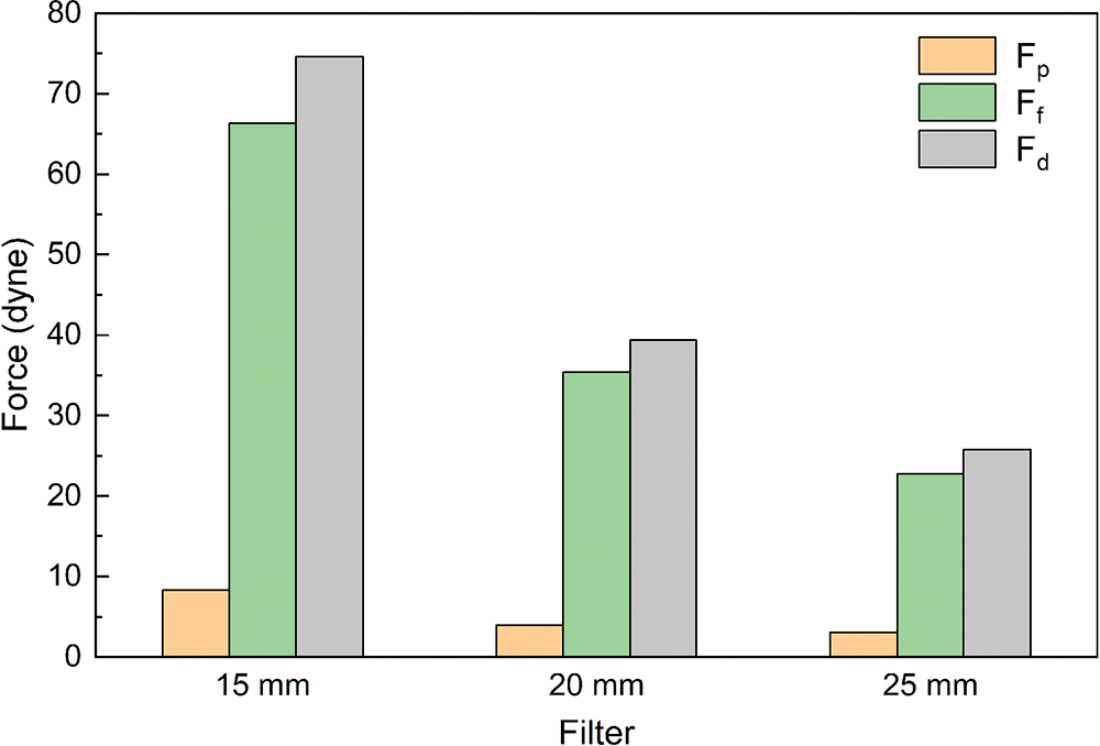
Figure 9: Viscous resistance, pressure difference resistance and flow resistance of filters
Wang et al. introduced relative flow resistance (RF) to evaluate the IVC patency [29]. The smaller the relative flow resistance, the better the IVC patency. The definition of relative flow resistance is as follows:
where ΔP is the pressure drop in the blood flow direction of the IVC segment with filter from z = −0.05 m to z = 0.01 m, ΔP0 is the pressure drop in the same length as ΔP when the filter is not implanted. Table 1 lists the pressure drop and relative flow resistance of filters with three diameters implanted in IVC. The filter with a diameter of 15 mm produced a large pressure drop, which was more than 70% of the 15 mm IVC-only case. With the decrease in IVC diameter, the pressure drop and relative flow resistance gradually increased.

The thrombus capture rate of the IVCF mainly depends on how the thrombus passes through the IVC, that is, depends on the hemodynamics in the IVC [38]. Both in vivo and in vitro experiments showed that the existence of the filter will cause disturbance to the blood flow [20]. The use effect of the filter depends on the IVC diameter of the patient, but its hemodynamics in IVC with different diameters has not been discussed. In this paper, the CFD method was used to compare the hemodynamic characteristics of three different diameter cases with IVCF implantation, including velocity distribution, WSS distribution and flow resistance. From the perspective of fluid mechanics, the impact of IVC diameter on the use of filters was explored.
Due to the influence of the filter wire with no-slip boundary conditions, the flow velocity of blood was low in the locality of the wire. At the same time, the wire guided the blood flow to converge in the conical area of the filter center, which had an accelerating effect on the blood flow. As a result, a “petal-shaped” blood flow distribution appeared in the cross-section of the filter, and an acceleration zone existed in the center of the filter, as shown in Fig. 3b. Wang et al. referred to the acceleration effect of the filter on blood flow as the “viscous block” effect [29].
The presence of a “petal-shaped” blood flow distribution in all three diameters indicated that the filter accelerated blood flow. In clinical practice, the high velocity flow in the accelerated zone of the filter can impact the blood near the filter head, thereby capturing the thrombus. The acceleration was most pronounced in the 15 mm diameter IVC under the same flow conditions and decreased with increasing diameter, which was closely related to the blood flow velocity in the IVC and was caused by the diameter difference. However, the difference in the length of the acceleration zone between the three diameters was not conspicuous when compared with the respective diameters of IVC-only, so the effect of the diameters on the length of the acceleration zone in the implanted filtered IVC was not significant.
4.2 Stagnation and Recirculation Zone
The stagnation and reflow zones occur in areas with large velocity differences, and both occur almost simultaneously, which is an ideal environment for thrombus growth [20]. Leask et al. found that stagnation and reflow zones occur downstream of the filter through in vitro experiments with TrapEase [27]; Aycock et al. reconstructed patient-specific IVC models from computed tomography (CT) data and performed CFD simulations, which showed the same stagnation and reflow zones downstream of the filter [26]. The experiments and simulations further confirmed the presence of stagnation and reflow areas downstream of the filter. Blood stagnation, endothelial damage and blood hypercoagulability are known as the three elements in Vichrow’s Triad [39]. Therefore, the stagnation and recirculation zones caused by filter implantation in the IVC may prevent thrombus lysis and even promote platelet deposition and fibrin mesh formation, leading to thrombosis [40,41].
Stagnation and reflow zones were present in all three sizes of the IVC, and the effect of IVC diameter on the length of the stagnation zone was more pronounced. The length of the stagnation zone in the 15 mm diameter IVC was the longest, almost 20 times its diameter, under the same flow; the length of the stagnation zone in the 20 and 25 mm diameter IVC was about 10 and 6 times its corresponding diameter. Accordingly, the filter in 15 mm diameter IVC had a higher risk of thrombotic regeneration downstream. However, the length downstream of a real IVC implanted filter is much less than the length demonstrated here. Therefore, the measurement of stagnation zone length as a potential factor in thrombosis was too simplistic and should be evaluated cautiously in the clinic.
Figs. 3–5 show that due to the rapid change in the blood flow velocity layer around the filter wire near the filter head, the WSS on the filter surface increased rapidly, as shown in Figs. 6 and 7. The area around the filter is divided into an upstream side and a downstream side, with the upstream side being the side facing the incoming flow. The upstream side is in direct contact with the incoming flow, which facilitates the dissolution of thrombi carried by the blood flow. The high WSS of the filter has a better effect on the prevention of PE [20,21]. The filter in 15 mm diameter IVC had a higher WSS peak along the upstream side, and the WSS distribution characteristics indicated that the 15 mm diameter case may have a better effect on the dissolution of thrombi compared to 20 and 25 mm diameter cases. However, in vitro experiments have also shown that higher WSS may also activate intravascular platelets, which in turn may lead to thrombus accumulation [42]. Further studies are required to confirm the clinical impact of the filter WSS.
Low WSS at the contact site between the IVC and the filter may lead to endothelial hyperplasia [26]. Endothelial hyperplasia has been found near the area of filter contact with the IVC in thromboembolic patients and animals [42]. Fig. 8 shows that the contact site between the 15 mm IVC and the filter had the lowest WSS, with a higher risk of endothelial hyperplasia in the IVC. Although the filter support filaments were ignored in the simulations of this study, it can be inferred from the WSS distribution at the contact point between the filter and the IVC that the risk of endothelial hyperplasia gradually increased as the IVC diameter decreased.
The ideal IVCF should not only have a high thrombus capture rate, but also maintain the IVC patency and reduce the obstruction to blood flow. This paper analyzed the flow resistance and relative flow resistance of filters with different diameter cases to comprehensively analyze the influence of the IVC diameter effect on flow resistance and IVC patency. The force exerted by blood flow on the filter surface not only reflects the force of the filter impeding blood flow, but also balances with the total force exerted by the filter on the IVC wall. The relative flow resistance can reflect the IVC patency and can further reflect the effect of different diameters on the resistance within the IVC.
The effect of diameter on the flow resistance and relative flow resistance is larger. Flow resistance and relative flow resistance were greatest in the case of 15 mm. The smaller the IVC diameter, the greater the resistance and the more pronounced the obstruction of blood flow by the filter, and therefore the poorer the IVC patency. Pressure resistance and viscous resistance together constitute the total resistance of the filter, in which viscous resistance made the greatest contribution to the total resistance. The pressure resistance is mainly related to the surface structure of the filter [22,32], and the vessel diameter effect has little effect on the differential pressure resistance.
Since the flow resistance can be balanced by the combined force of the filter fixed in the IVC wall, it can reflect the potential tendency of filter fracture and displacement. Filter fracture is a common complication [43]. The smaller the vessel diameter, the greater the flow resistance, and it can be inferred that the possibility of deformation or even fracture and displacement of the filter was greater. When a filter captures a thrombus in the IVC, the flow resistance of blood flow increases and the filter exerts a greater force on the IVC wall than it would in the absence of a thrombus [32], which may make it more likely that the filter will tilt, fracture, or even displace.
In this paper, CFD methods were used to investigate the effect of different IVC diameters on the IVC hemodynamics after filter implantation. Due to the limitations of the CFD model used, this study had several shortcomings. Firstly, due to the lack of clinical data and more comprehensive patient information, a simplified homogeneous circular tube model was used in this study, whereas the patient has an IVC with iliac and renal veins and an irregular cross-section of the IVC [10,22,26]. Due to the low pulsatility and pressure of the blood flow, this study ignored the elasticity of the vessel, considered the IVC as a rigid vessel, and set the flow as steady flow. However, when the filter implantation is successful and the cardiac cycle does not have a significant effect on the shape of the IVC, with the vessel not being overly flattened, the applicability of the conclusions is still relatively well established. Secondly, this study did not model the process of thrombus interception in the IVC, however, thrombus can have a large impact on the flow in the IVC [32]. Thirdly, in this paper, only one type of filter which is most commonly used in the clinic was simulated to investigate the effect of IVC diameter effect on blood flow after filter implantation, while the flow characteristics vary significantly among different filters, and further studies are needed to confirm this. Finally, in section “Stagnation and Recirculation Zone”, the stagnation zone length was proposed to act as a direct factor in thrombosis. According to this indicator, it was clearly seen that thrombosis was most likely to accumulate downstream of the 15 mm filter head. However, this did not balance that higher velocity in blood flow downstream of the 15 mm IVC filter head will delay thrombus growth, which needs to be rigorously tested for clinical use.
In this study, CFD simulations were used to assess the IVC hemodynamic effects. The effect of vessel diameter on the flow field distribution, WSS distribution and flow resistance in the IVC after the filter implantation was investigated using 15, 20 and 25 mm diameters based on the VenaTech convertible filter. The main findings are as follows:
(1) Changes in IVC diameter have little effect on the flow velocity distribution pattern around the filter, and acceleration, stagnation and recirculation zones appeared around the filter at all three IVC diameters. The decrease of the diameter could enhance the “viscous block” effect in the IVC, while the diameter has little effect on the length of the flow acceleration zone. The stagnation zone downstream of the filter head after implantation is significantly affected by the IVC diameter, and it becomes more severe as the diameter decreases. 15 mm diameter case had a stagnation zone almost 20 times longer than the IVC diameter. The stagnation and reflow zone may be the area of thrombus formation, and the smaller the diameter, the higher the possibility of thrombus regeneration.
(2) Under the condition of different diameters, the WSS peak along the upstream side filter is significantly different. The smaller the IVC diameter, the greater the WSS peak. However, the WSS distribution on the downstream side of the filter has little difference. The WSS peak exceeded 20 times that of the IVC-only at 15 mm diameter, which requires to be confirmed in further clinical studies whether this is beneficial to patients. IVC diameter also affects IVC WSS, with the degree of effect gradually increasing as the IVC diameter decreases, with the most significant effect occurring at 15 mm diameter case. Low WSS at the contact between the IVC and the filter may lead to intimal hyperplasia.
(3) With the same flow rate, viscous resistance and flow resistance increase as the IVC diameter decreases, and relative flow resistance increases gradually. The results showed that the flow resistance and relative flow resistance under 15 mm diameter case were significantly higher than those under 20 and 25 mm diameter. Therefore, the 15 mm IVC patency is the worst among the three tube diameters and may be more prone to filter tilting, fracture or even displacement.
Acknowledgement: None.
Funding Statement: This research was funded by Young Scholar’s Future Plan of Shandong University, Grant Number 31380082164048.
Author Contributions: The authors confirm contribution to the paper as follows: study conception and design: J.W. and W.H.; data collection: S.Z., J.W., X.S. and Y.Z.; analysis and interpretation of results: S.Z., J.W., X.S. and M.L.; draft manuscript preparation: S.Z. and W.H. All authors reviewed the results and approved the final version of the manuscript.
Availability of Data and Materials: The data and materials of this study are available from the corresponding author.
Conflicts of Interest: The authors declare that they have no conflicts of interest to report regarding the present study.
References
1. Licha, C. R. M., McCurdy, C. M., Maldonado, S. M., Lee, L. S. (2020). Current management of acute pulmonary embolism. Annals of Thoracic and Cardiovascular Surgery, 26(2), 65–71. [Google Scholar]
2. Duffett, L., Castellucci, L. A., Forgie, M. A. (2020). Pulmonary embolism: Update on management and controversies. British Medical Journal, 370, M2177. [Google Scholar] [PubMed]
3. Wenger, N., Sebastian, T., Engelberger, R. P., Kucher, N., Spirk, D. (2021). Pulmonary embolism and deep vein thrombosis: Similar but different. Thrombosis Research, 206, 88–98. [Google Scholar] [PubMed]
4. Choi, J. H., Lee, S. Y., Park, Y. H., Park, J. H., Kim, K. H. (2020). In-hospital outcome in patients underwent extracorporeal membrane oxygenation in life-threatening high-risk pulmonary embolism. International Journal of Heart Failure, 2(3), 187–194. [Google Scholar] [PubMed]
5. Jamil, A., Johnston-Cox, H., Pugliese, S., Nathan, A. S., Fiorilli, P. et al. (2021). Current interventional therapies in acute pulmonary embolism. Progress in Cardiovascular Diseases, 69, 54–61. [Google Scholar] [PubMed]
6. Freund, Y., Cohen-Aubart, F., Bloom, B. (2022). Acute pulmonary embolism: A review. The Journal of the American Medical Association, 328(13), 1336–1345. [Google Scholar] [PubMed]
7. Ortel, T. L., Neumann, I., Ageno, W., Beyth, R., Clark, N. P. et al. (2020). American society of hematology 2020 guidelines for management of venous thromboembolism: Treatment of deep vein thrombosis and pulmonary embolism. Blood Advances, 4(19), 4693–4738. [Google Scholar] [PubMed]
8. Klok, F. A., Piazza, G., Sharp, A. S., Ainle, F. N., Jaff, M. R. et al. (2022). Ultrasound-facilitated, catheter-directed thrombolysis vs anticoagulation alone for acute intermediate-high-risk pulmonary embolism: Rationale and design of the HI-PEITHO study. American Heart Journal, 251, 43–53. [Google Scholar] [PubMed]
9. He, J., Wang, Z., Zhou, Y. X., Ni, H., Sun, X. et al. (2022). The application of inferior vena cava filters in orthopaedics and current research advances. Frontiers in Bioengineering and Biotechnology, 10, 1045220. [Google Scholar] [PubMed]
10. Chen, Y., Zhang, P., Deng, X., Fan, Y., Xing, Y. et al. (2017). Improvement of hemodynamic performance using novel helical flow vena cava filter design. Scientific Reports, 7(1), 40724. [Google Scholar] [PubMed]
11. Déan, C., Kim, Y. I., Sanchez, O., Martelli, N., Sapoval, M. et al. (2022). Safety and efficacy of the VenaTech retrievable inferior vena cava filter: A first-in-man single-center prospective study. CVIR Endovascular, 5(1), 1–8. [Google Scholar]
12. Gillespie, D. L., Spies, J. B., Siami, F. S., Rectenwald, J. E., White, R. A. et al. (2020). Predicting the safety and effectiveness of inferior vena cava filters study: Design of a unique safety and effectiveness study of inferior vena cava filters in clinical practice. Journal of Vascular Surgery: Venous and Lymphatic Disorders, 8(2), 187–194. [Google Scholar] [PubMed]
13. Winokur, R. S., Bassik, N., Madoff, D. C., Trost, D. (2019). Radiologists’ field guide to retrievable and convertible inferior vena cava filters. American Journal of Roentgenology, 213(4), 768–777. [Google Scholar] [PubMed]
14. Law, Y., Chan, Y. C., Cheng, S. W. K. (2018). Epidemiological updates of venous thromboembolism in a Chinese population. Asian Journal of Surgery, 41(2), 176–182. [Google Scholar] [PubMed]
15. Wang, S. L., Siddiqui, A., Rosenthal, E. (2016). Long-term complications of inferior vena cava filters. Journal of Vascular Surgery Venous & Lymphatic Disorders, 5(1), 33–41. [Google Scholar]
16. Hohenwalter, E. J., Stone, J. R., O’Moore, P. V., Smith, S. J., Selby, J. B. et al. (2017). Multicenter trial of the VenaTech convertible vena cava filter. Journal of Vascular and Interventional Radiology, 28(10), 1353–1362. [Google Scholar] [PubMed]
17. Sheahan, K. P., Tong, E., Lee, M. J. (2023). A review of inferior vena cava filters. The British Journal of Radiology, 96(1141), 20211125. [Google Scholar] [PubMed]
18. Huang, S. Y., Damasco, J. A., Tian, L., Lu, L., Melancon, M. P. (2020). In vivo performance of gold nanoparticle-loaded absorbable inferior vena cava filters in a swine model. Biomaterials Science, 8(14), 3966–3978. [Google Scholar] [PubMed]
19. Shahid, M. U., Nirgudkar, N., Chandra, V., Gonzales, S., Kumar, A. (2022). Influence of exercise on inferior vena cava wall interaction with inferior vena cava filters: Results of a pilot in vivo porcine study. The Arab Journal of Interventional Radiology, 6(2), 72–75. [Google Scholar]
20. Stewart, S. F. C., Robinson, R. A., Nelson, R. A., Malinauskas, R. A. (2008). Effects of thrombosed vena cava filters on blood flow: Flow visualization and numerical modeling. Annals of Biomedical Engineering, 36(11), 1764–1781. [Google Scholar] [PubMed]
21. Turitto, V. T., Hall, C. L. (1998). Mechanical factors affecting hemostasis and thrombosis. Thrombosis Research, 92(6), S25–S31. [Google Scholar] [PubMed]
22. Lopez, J. M., Fortuny, G., Puigjaner, D., Herrero, J., Marimon, F. (2018). A comparative CFD study of four inferior vena cava filters. International Journal for Numerical Methods in Biomedical Engineering, 34(7), e2990. [Google Scholar] [PubMed]
23. Singer, M. A., Wang, S. L. (2011). Modeling blood flow in a tilted inferior vena cava filter: Does tilt adversely affect hemodynamics? Journal of Vascular and Interventional Radiology, 22(2), 229–235. [Google Scholar] [PubMed]
24. Prince, M. R., Novelline, R. A., Athanasoulis, C. A., Simon, M. (1983). The diameter of the inferior vena cava and its implications for the use of vena caval filters. Radiology, 149(3), 687–689. [Google Scholar] [PubMed]
25. Dowell, J. D., Castle, J. C., Schickel, M., Andersson, U. K., Zielinski, R. et al. (2015). Celect inferior vena cava wall strut perforation begets additional strut perforation. Journal of Vascular and Interventional Radiology, 26(10), 1510–1518. [Google Scholar] [PubMed]
26. Aycock, K. I., Campbell, R. L., Manning, K. B., Sastry, S. P., Shontz, S. M. et al. (2014). A computational method for predicting inferior vena cava filter performance on a patient-specific basis. Journal of Biomechanical Engineering, 136(8), 081003. [Google Scholar]
27. Leask, R. L., Johnston, K. W., Ojha, M. (2004). Hemodynamic effects of clot entrapment in the TrapEase inferior vena cava filter. Journal of Vascular & Interventional Radiology, 15(5), 485–490. [Google Scholar]
28. Tedaldi, E., Montanari, C., Aycock, K. I., Sturla, F., Redaelli, A. et al. (2018). An experimental and computational study of the inferior vena cava hemodynamics under respiratory-induced collapse of the infrarenal IVC. Medical Engineering & Physics, 54, 44–55. [Google Scholar]
29. Wang, J., Huang, W., Zhou, Y., Han, F., Ke, D. et al. (2020). Hemodynamic analysis of VenaTech convertible vena cava filter using computational fluid dynamics. Frontiers in Bioengineering and Biotechnology, 8, 556110. [Google Scholar] [PubMed]
30. Li, M., Wang, J., Huang, W., Zhou, Y., Song, X. (2022). Evaluation of hemodynamic effects of different inferior vena cava filter heads using computational fluid dynamics. Frontiers in Bioengineering and Biotechnology, 10, 1034120. [Google Scholar] [PubMed]
31. Amiri, M. H., Keshavarzi, A., Karimipour, A., Bahiraei, M., Goodarzi, M. et al. (2019). A 3-D numerical simulation of non-Newtonian blood flow through femoral artery bifurcation with a moderate arteriosclerosis: Investigating Newtonian/non-Newtonian flow and its effects on elastic vessel walls. Heat and Mass Transfer, 55, 2037–2047. [Google Scholar]
32. Lopez, J. M., Fortuny, G., Puigjaner, D., Herrero, J., Marimon, F. (2020). Hemodynamic effects of blood clots trapped by an inferior vena cava filter. International Journal for Numerical Methods in Biomedical Engineering, 36(7), e3343. [Google Scholar] [PubMed]
33. Boniforti, M. A., Magini, R., Orosco Salinas, T. (2023). Hemodynamic investigation of the flow diverter treatment of intracranial aneurysm. Fluids, 8(7), 189. [Google Scholar]
34. Hassan, M., Issakhov, A., Khan, S. U. D., Assad, M. E. H., Hani, E. H. B. et al. (2020). The effects of zero and high shear rates viscosities on the transportation of heat and mass in boundary layer regions: A non-Newtonian fluid with carreau model. Journal of Molecular Liquids, 317, 113991. [Google Scholar]
35. Baraikan, A. A., Czechowicz, K., Morris, P. D., Halliday, I., Gosling, R. C. et al. (2023). Modelling the hemodynamics of coronary ischemia. Fluids, 8(5), 159. [Google Scholar]
36. Cheng, C. P., Herfkens, R. J., Taylor, C. A. (2003). Inferior vena caval hemodynamics quantified in vivo at rest and during cycling exercise using magnetic resonance imaging. American Journal of Physiology-Heart & Circulatory Physiology, 284(4), H1161–H1167. [Google Scholar]
37. Gallagher, M. B., Aycock, K. I., Craven, B. A., Manning, K. B. (2018). Steady flow in a patient-averaged inferior vena cava—Part I: Particle image velocimetry measurements at rest and exercise conditions. Cardiovascular Engineering and Technology, 9(4), 641–653. [Google Scholar] [PubMed]
38. Selimli, S. (2022). Investigation the helical strut attached vena cava filter hemodynamic performance. Journal of Engineering Research, 10(2B), 174–183. [Google Scholar]
39. Lurie, J. M., Png, C. M., Subramaniam, S., Chen, S., Chapman, E. et al. (2019). Virchow’s triad in “silent” deep vein thrombosis. Journal of Vascular Surgery: Venous and Lymphatic Disorders, 7(5), 640–645. [Google Scholar] [PubMed]
40. Lowe, G. D. (2003). Virchow’s triad revisited: Abnormal flow. Pathophysiology of Haemostasis and Thrombosis, 33(5–6), 455–457. [Google Scholar] [PubMed]
41. Bovill, E. G., Vliet, A. V. D. (2011). Venous valvular stasis–associated hypoxia and thrombosis: What is the link? Annual Review of Physiology, 73(1), 527–545. [Google Scholar] [PubMed]
42. McCowan, T. C., Ferris, E. J., Carver, D. K. (1990). Inferior vena caval filter thrombi: Evaluation with intravascular US. Radiology, 177(3), 783–788. [Google Scholar] [PubMed]
43. Li, X., Haddadin, I., McLennan, G., Farivar, B., Staub, D. et al. (2020). Inferior vena cava filter–comprehensive overview of current indications, techniques, complications and retrieval rates. European Journal of Vascular Medicine, 49(6), 449–462. [Google Scholar] [PubMed]
Cite This Article
 Copyright © 2023 The Author(s). Published by Tech Science Press.
This work is licensed under a Creative Commons Attribution 4.0 International License , which permits unrestricted use, distribution, and reproduction in any medium, provided the original work is properly cited.
 Downloads
 Citation Tools