
 Submit a Paper
 Propose a Special lssue
 Open Access
ARTICLE

Study on the Application of Vibration Isolation by Using a Trench in Frame Structures
1 Zhengzhou University, Zhengzhou, 450002, China
2 Henan Xixi Expressway Construction Co., Ltd., Nanyang, 450015, China
* Corresponding Author: Shizhan Xu. Email:
Structural Durability & Health Monitoring 2023, 17(1), 23-36. https://doi.org/10.32604/sdhm.2023.011383
Received 05 May 2020; Accepted 20 November 2020; Issue published 02 March 2023
 View Full Text
 Download PDF
Abstract
An isolation trench is a simple and effective method to isolate structural vibrations originating from sources of vibration other than earthquakes (machines, traffic, explosions, etc.); however, there is still not a conclusive depth of the isolation trench for frame structures. To investigate the isolation effect of a trench in the frame structure designed for ground vibration, both a field test and finite element analysis were conducted to analyze the reduced effect of the vibration. The vibration reduction analysis was based on the dynamic equation and wave theory. Considering the vibration control of an industrial plant frame, a soil-trench-building finite element model was built to analyze the vibration characteristics of the floor before and after the open isolation trench structure was used. According to the model, a dynamic test was carried out on the frame structure to assess the effect of the vibration reduction by introducing the trench. The results showed that the depth of the trench was the dominating factor in vibration isolation. When the depth of the trench reached 1~1.3 times the wavelength of the Rayleigh wave, the damping effect was the strongest. the width of the trench has little effect on the vibration isolation efficiency, and the trench must be maintained at a certain distance from the building to ensure the vibration damping efficiency. The vibration of each floor was obviously reduced after the trench was built. The vibration damping effect of the trench was significant.Keywords
With the rapid development of social economy, the scale of urban infrastructure construction was constantly expanding. However, the situation also brought a lot of issues. For example, Vibrations originating from vibrating machines, traffic, and blasting often have a negative influence on our daily lives, not only on nearby buildings, but on high-precision equipment. A frame structure is prone to resonance with ground vibration because of its small lateral stiffness. At present, the installation of vibration isolation barrier is one of the methods to solve this environmental vibration. Compared with the traditional vibration isolation method, the barrier isolation method has many advantages, including low cost, firmness, high durability, back filling easily after construction and not affecting the normal use of the building during the entire construction process. Much literature can be found about isolation trenches; however, the cost of field test of isolation trenches is so high, and the reliable data can be obtained is very limited, that it is important to use these data to conduct further study on seismic effect of isolation trenches on frame structure. Therefore, it is of great significance to simulate the vibration process by numerical simulation method and compare it with field experiment.
In order to know the influence mechanism of vibration damping effect of the trench, Barkan [1] researched the effect of vibration isolation using barriers at first, such as vibration reduction by a trench and pile wall; however, the effect was not adequate. Subsequently, Woods et al. [2] proposed the concept of the amplitude attenuation coefficient through a series of in situ field tests on active vibration isolation and passive vibration isolation of the trench method, established the foundation of attenuation coefficient research. Later, there are more and more researches on isolation trench. A numerical model composed of a train-track dynamics sub-model and a track-soil-building finite element sub-model was developed by Zou et al. [3] to study the vibration isolation efficiency of various wave barriers including trenches and concrete walls. The finite element analysis and the model test were carried out by Haupt et al. [4,5] to study the effects of filled trenches on the scattering of waves, and the results showed that the bright scattering effect is related to the cross-sectional area of the barrier but not to the shape of the barrier. Rigidity barriers are much more effective than flexible barriers. Bose et al. [6] and Lei et al. [7] researched the key factors affecting the vibration isolation efficiency of open and infill trenches. Eskandarighadi et al. [8,9] investigated the isolation efficacy of geocell-reinforced foundation beds infilled with different materials through a series of block resonance tests. Sarka et al. [10] investigated the efficiency of using sand crumb rubber mixture for vibration isolation. Zhou et al. [11] found that the vibration isolation performance of the open trench–wave impedance block barrier system can reduce the vibration generated by a vibration source. 3D FEM model was constructed by Kontoni et al. [12] to study the train-induced vibrations on a nearby high-rise building. The attenuation response from a series of block vibration tests performed on a model square machine foundation at a site near IIT Kanpur, India, is studied by Surapreddi et al. [13]. A finite-element method based on a partial differential equation is introduced by Meng et al. [14] to study the propagation and attenuation of plane waves in single-phased soil by pile barriers. Majumder et al. [15] studied the performance of intermittent geofoam in-filled trench as a passive vibration screening when a reinforced concrete lining tunnel is subjected to internal blast load. Hegde et al. [16] studied the performance of the barriers created using geosynthetics in mitigating the vibrations. Jazebi et al. [17–19] proposed a novel approach which is considering the effect of Rayleigh wavelength on the efficiency of open and in-filled trenches coupled with regular specific normalized dimensions was implemented . Çelebi et al. [20] and Sivakumar Babu et al. [21] conducted field experiments on wave propagation and vibration isolation using wave barriers.
In summary, the research about vibration damping effect of the trench was still insufficient, for the reason that the high cost of field test of isolation trenches, it is of great significance to simulate the vibration process by numerical simulation method. This paper compared the result of finite element analysis and the result of field test about isolation trenches and analyzed best depth of the isolation trench. Besides, the paper analyzed the locations and widths of the isolation trenches to provide a theoretical basis for the scope of building protection.
2 Vibration Isolation Mechanism of Barriers
A vibration generated by the external environment is propagated out of the vibration source in waves. When a wave propagates to the interface of two layers, reflection and refraction will occur at the interface. The mechanism of the barrier isolation is to reduce the energy of the wave reaching the target building. One part of the wave will be reflected according to the reflection theory in optics and acoustics while it propagates to the interface of two different elastic media, and the other part of the wave is transmitted to another medium. The barrier isolation mechanism has been discussed further based on the reflection of the longitudinal wave and shear wave. When the P wave propagates to the interface of the two layers, two reflection waves and two refracted waves are produced (see Fig. 1), according to Snell’s law [22]:
where Vp1 and Vs1 are the longitudinal wave velocity and the shear wave velocity in the first medium, respectively, and Vp2 and Vs2 are the longitudinal wave velocity and the shear wave velocity in the second medium, respectively. If the amplitude of the incident wave is shown as A1, then the amplitudes of the reflected and transmitted waves are shown as A2 and A3; the propagation of the waves at different media interfaces is assumed by the boundary condition [23] in the case of the vertical incidence (α1 = 0) characteristic:
Because the shear wave is perpendicular to the propagation surface of the wave, the SH wave does not produce the P wave in reflection or transmission. However, the SV wave is accompanied by a P wave when it is reflected and transmitted, and it also produces four waves because the vibration direction of the SV wave is consistent with the propagation direction of the wave. The waves satisfy the following relationship:
ρV is defined as the wave impedance of the medium where ρ is the density and V is the wave velocity. Eq. (2) shows that the amplitudes of the reflected and transmitted waves depend on the wave impedance ratio and angle of incidence. The greater the difference in wave impedance between the two interfaces is, the smaller the total energy of the refraction. Thus, the reduction effect of the barrier is better.
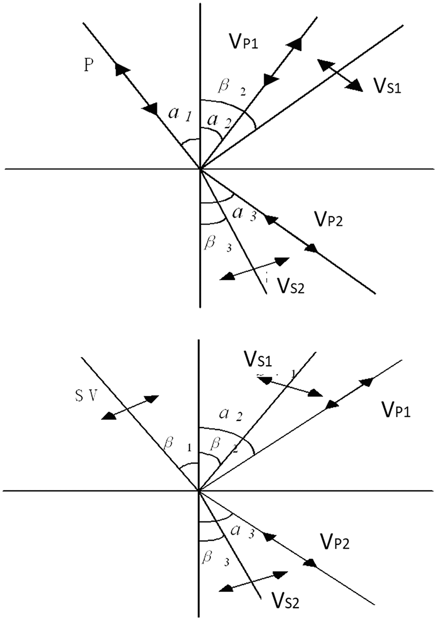
Figure 1: Incident and refraction of different waves
3 Numerical Analysis of Reduction Effect of Trench
The analysis is carried out by ANSYS 17.2 software. Plane 182 is chosen to simulate the main soil body, and the field is regarded as a semi-infinite body. This unit has 4 nodes, each with two degrees of freedom: displacement in the x and y directions. This unit has plasticity, superelasticity, stress stiffness, large deformation and large strain capability. The solid was analyzed and calculated based on the plane strain [24]. In addition, to avoid the impact of wave reflection on the simulation results, a visco-elastic artificial boundary was applied to the model. The visco-elastic boundary can not only overcome the problem of low-frequency drift caused by a viscous boundary but also simulate the elastic recovery performance and scattered wave radiation of the semi-infinite foundation of an artificial boundary. Both the low-frequency and high-frequency stability [24] of this method are good. Two-dimensional models that were 100 m × 50 m in size with a graticule mesh were adopted in this study. The vibrating source was 3 m away from the left edge of the trench, the initial elastic modulus was 2.6 × 10² MPa, the soil density was 2000 kg/m3, the Poisson’s ratio was 0.495, the Raleigh damping was 0.025, and the main body was meshed by 0.5 m. The load was an impact load with a magnitude of 10 kN, which was achieved by a step load in ANSYS; the time step was 0.005 s. The finite element dynamic model is shown in Fig. 2.
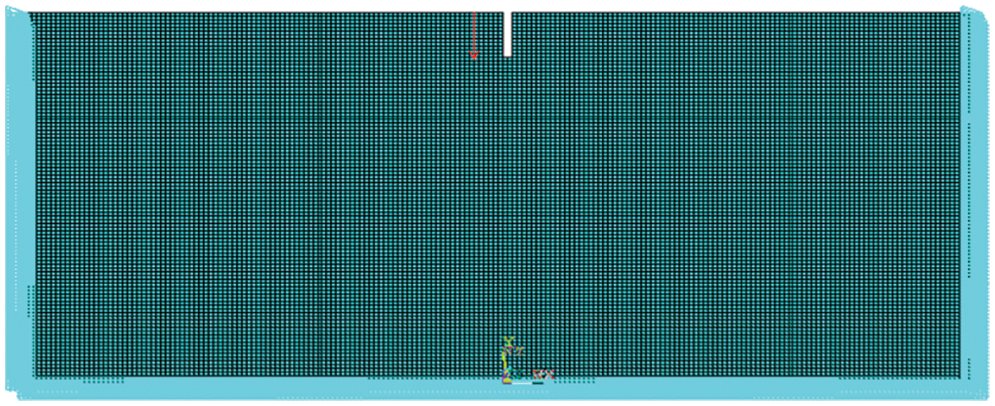
Figure 2: Finite element model of the soil trench
3.1 Vibration Reduction Effect of the Trench Depth
When fixing the width of the trench as 0.5 m, the depth of the trench was described as a dimensionless parameter d*, d* = d/λR, where λR was the Rayleigh wavelength. The normalized depths of each trench were assumed to be 0, 0.1, 0.3, 0.5, 0.7, 0.9, 1, 1.1, 1.3, 1.5, 2 and 2.5. Instantaneous dynamic analysis was used to calculate the time-history response from 0–1 s at the target point. The amplitude attenuation coefficient ARF (acceleration amplitude with the barrier/ acceleration amplitude without the barrier), was proposed by Woods [2], which is used to measure the reduction effect of the trench for the frame structures. The distances of A, B, C, D, E and F from the edge of the trench are 1, 3, 5, 7, 10, and 20 m, respectively.
The acceleration attenuation coefficients are shown in Fig. 3.
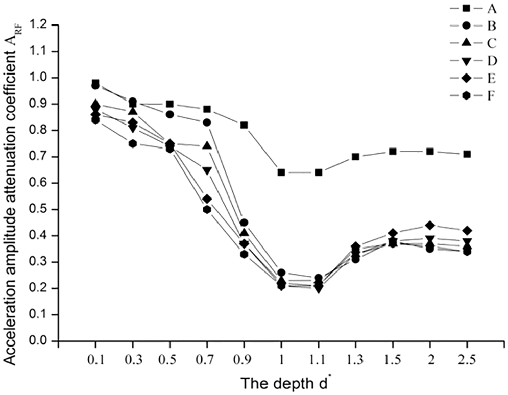
Figure 3: ARF of different trench depths
The ARF of each measuring point is shown to first decrease, and then increase with increasing trench depth, but the ARF of A curve decreased significantly less than other curves. When the depth is 0.1λR~0.5λR, The attenuation of acceleration amplitude of each curve are between 10% and 20%. At this time, the ARF attenuation of A and B curves is about 10%, and the ARF attenuation C, D, E and F curves is about 20%. With the increase of trench depth, the amplitude of acceleration decreases gradually. When the depth reaches 0.7λR, the ARF attenuation of A and B curves is still about 10%, and the ARF attenuation of C, Dcurve are 20% and 30%, respectively, and the ARF attenuation of E and F curves are 50% lower than compared with them in 0.1λR. When the depth reaches 0.9λR, the ARF attenuation of A curve is still 10%, and the ARF of B, C, D, E and F curves decreases rapidly by 45%, 40%, 35% and 30% respectively. When the depth reaches 1λR~1.1λR, the amplitude acceleration of every measuring point decreases most, B-F measuring point can reduce 80% and a measuring point can reduce 35%. However, when the depth is lower than 1.3λR, ARF increases and the reduction effect of trench decreases, but the degree of reduction is very small. ARF attenuation of B-F measuring point rises to about 40%, and ARF of measuring point a rises to 35%. In conclusion, deeper trench does not result in better reduction effect.
3.2 Vibration Reduction Effect of the Trench Width
The depth d* was fixed to 0.9; the distance from the vibration source was constant. The normalized widths of each trench were assumed to be 0.5, 1, 1.5, and 2 m. Instantaneous dynamic analysis was used to calculate the time-history response from 0–1 s at the target point. The results are shown in Fig. 4.
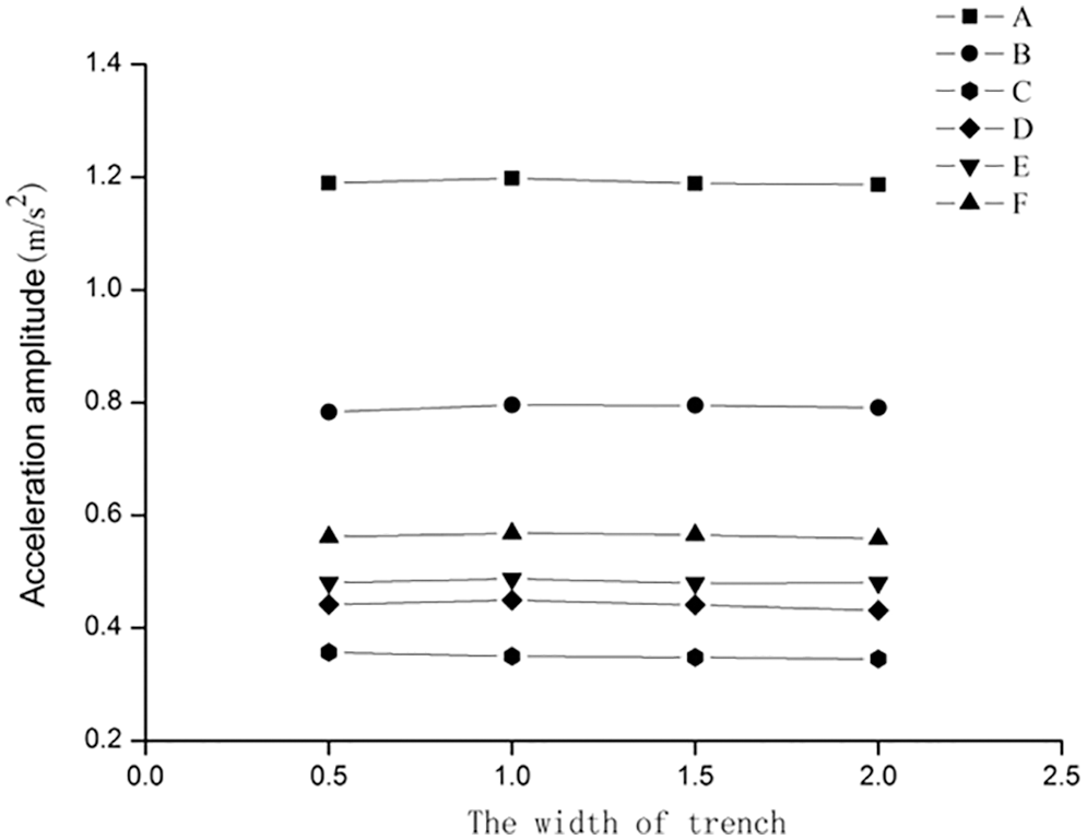
Figure 4: Graph of acceleration amplitude for different widths
No significant difference was observed in the maximum acceleration response when the width was increased. The results indicate that the width has no impact on the reduction effect of the trench. This is because the width of the trench was relatively small compared with the wavelength in the soil, which generates minor energy loss caused by the vibration wave through the barrier; the reduction effect did not change with increasing width. Therefore, the width of the trench can be estimated from the principle of convenient construction, and construction cost can be estimated based on the actual conditions of the building.
3.3 Vibration Reduction Effect of the Trench’s Position
When the trench was constructed, its depth and width were restricted to construction conditions, construction safety, building influences, etc. However, when the depth was insufficient, a low-frequency vibration with a large wavelength would pass through from the bottom of the trench and continue to vibrate in the back region; therefore, the position of the trench (distance from the building) was the main factor affecting the vibration wave diffraction.
To determine the vibration reduction region of the trench, the normalized depths d* of each trench are assumed to be 0.9, 1, 1.1, 1.3 and 1.5. Instantaneous dynamic analysis was used to calculate the time-history response from 0–1 s at the target point. The results are shown in Fig. 5.
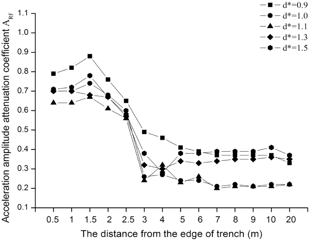
Figure 5: Graph of ARF
The attenuation coefficient of the acceleration first increases, then decreases and finally stabilizes following the increase in the distance from the trench’s edge. When the distance from the trench’s edge is small, the acceleration amplitude attenuation is small and the vibration reduction effect is weak. Because the wave passed through the bottom of the trench, ARF shows a certain increasing trend when the point is close to the trench’s edge but the effect is weak. Therefore, in order to ensure the reduction effect of the trench, the building must maintain a certain distance from the trench’s edge. With the increased distance from the trench’s edge, ARF began to decrease, and the vibration-reduction effect of the trench was obviously enhanced. Then, the attenuation coefficient of the acceleration was slightly floating; however, the range was small. The reduction effect was basically the same; the acceleration amplitude attenuation was reduced by 60%, and the vibration-reduction effect was good.
4 Study on Vibration Control of a Frame Structure
In this study, an industrial workshop, which is built by frame structure and located in Shenzhen Industrial Park, is taken as the analysis object. The frame structure has five floors, the first floor is 5.4 meters high, the other floors are 2.4 m high. The frame structure is 40 m in length and 20 m in width. The total floor area is about 800 m2, and the indoor and outdoor height difference is 0.3 m. The seismic fortification intensity of frame structure workshop is 7 degree [25], and the reasonable service life of the building is 50 years. The floor vibration of a five-story frame structure was too strong as a result of the vibration caused by machines in the surrounding plant. The production staff could clearly feel the vibration, and the study found in dynamic testing, the vertical vibration acceleration amplitude was too large. Therefore, in order to ensure normal use of the production workshop and effectively control the floor vibration, the trench was designed around the industrial plant.
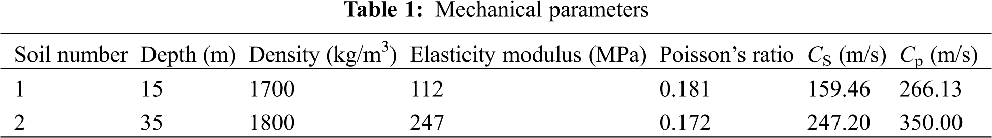
The dynamic strain amplitude in the soil caused by mechanical production, forging and other surrounding environment vibration is small, generally less than 10−5, so the soil can be considered an elastic medium. The soil can be regarded as a homogeneous isotropic elastomer for the calculations in this research. The soil should be calculated as the plane strain, ignoring the influence caused by temperature. Plane182 is chosen to simulate the main soil body. The soil site type was the same as the actual frame structure type, whose soil site type was the second site type defined in the Chinese design code as seismic; however, it can also be based on similar soil data to determine the specific soil dynamic parameters when the means necessary to survey the reference are lacking [26,27]. The soil dynamic parameters are shown in Table 1; the site boundary was consistent with the previous model, and the site damping ratio was 0.05.
The upper structure model was simulated by the plane frame, and the frame beam and column were simulated by the two-dimensional elastic beam element BEAM3. The main structural properties were as follows: the grade of the concrete strength was C30, the density was 2500 kg/m3, the concrete elastic modulus was 3.0 × 10⁴ MPa, and the Poisson’s ratio was 0.2. The upper beam element and the soil plane element were connected by the constraint equation method.
Former finite element analysis results showed that depth is the main factor affecting the vibration reduction effect of the trench. When the depth reaches 1~1.1λR, the amplitude acceleration of the measuring point decreases the most, indicating that the reduction effect is the best. By continuing to increase the depth, the reduction effect will be slightly reduced, so when the vibration is controlled, the depth should not continue to increase. Otherwise, it will not only cause difficulty in the construction but also waste manpower and material resources. When the depth is large, the stability of the trench’s sidewall will be influenced. Research from some scholars has shown that when the depth is larger than 1.33 times the Rayleigh wave wavelength in the base, the trench can achieve a better reduction effect. In this paper, the embedded depth of the foundation was chosen to be 3 m, the maximum shear wave velocity was 247 m/s, and the Rayleigh wave velocity was approximately 0.95 times the shear wave velocity. Therefore, the Rayleigh wave velocity was 234.7 m/s, and the Rayleigh wave’s frequency was taken to be 100 Hz; thus, the wavelength of the Rayleigh wave is 2.4 m. Therefore, the depth of the trench was taken as 3–4 m, meeting the vibration reduction requirements. The depth of the model was set to 3.0, 3.5 and 4.0 m to define the optimal depth of the trench; this was used to further analyze the relationship between the trench’s depth and the depth of the foundation.
Because the width had a minimal effect on the trench’s vibration reduction effect, the width can be estimated from convenient construction and cost based on the actual conditions of the building. Therefore, the width was defined as 1.0 m. The isolation trench should maintain a certain distance from the building to ensure the vibration reduction effect. Therefore, according to the actual depth of the trench, the position is determined to be 1~2 times the depth away from the building, so the distance is set to 7 m from the edge of the building. The soil-trench-building finite element model is shown in Fig. 6.
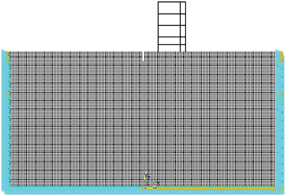
Figure 6: Finite element model of the soil-trench-building
4.2.2 Analysis and Evaluation of Vibration Reduction Effect
Based on the transient dynamic analysis in the ANSYS software structural analysis, the vertical acceleration amplitude of each floor was used to analyze and evaluate the vibration reduction effect after the trench was constructed. The five-floor acceleration-time curve is shown in Fig. 7. The variable d represents the depth of the trench in Fig. 7.
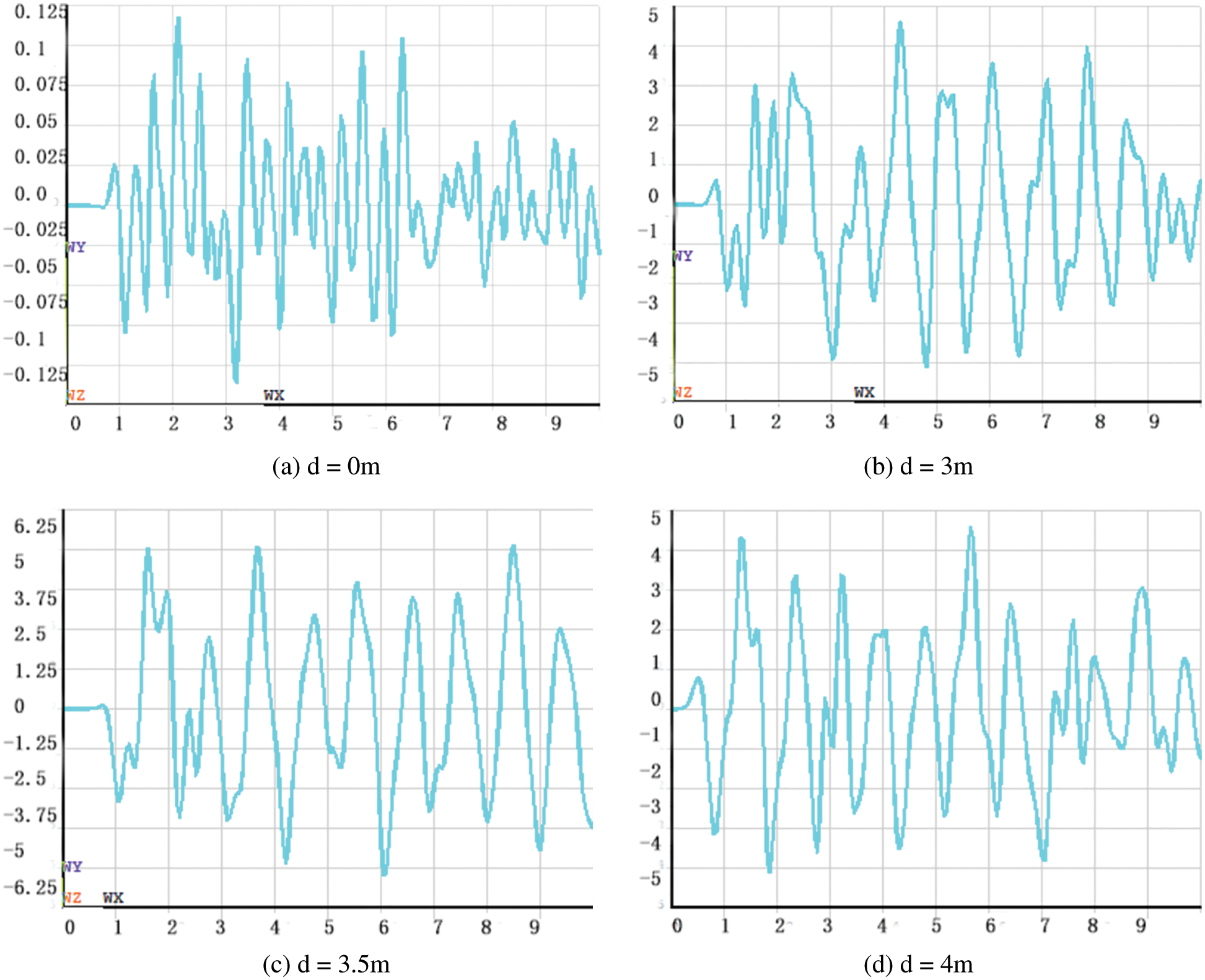
Figure 7: The five floor acceleration-time curve
The acceleration amplitude of each floor for different depths is shown in Table 2 and Fig. 8.
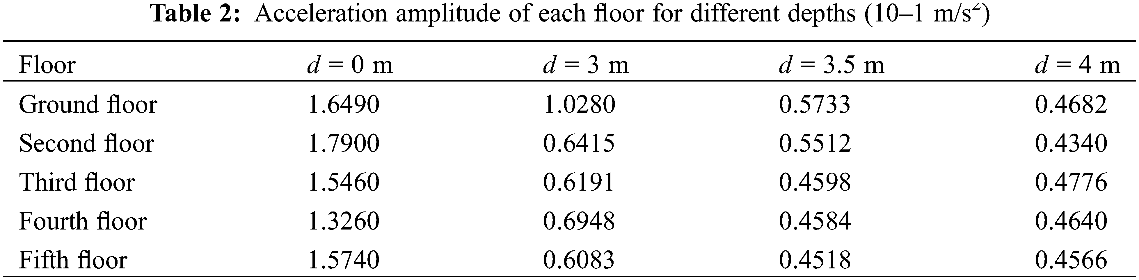
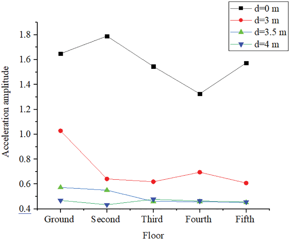
Figure 8: Acceleration amplitude of each floor for different depths (10–1 m/s2)
The vertical vibration acceleration amplitude of each floor was significantly reduced after the trench was constructed, the vibration of the upper floor was effectively reduced and the vibration reduction effect was significant. In addition, when the depth of the trench was the same as the embedded depth of the foundation, the vibration acceleration amplitude attenuation of the ground was reduced by 40%; however, when the depth was larger than the embedded depth of the foundation, it was reduced by 70%. Therefore, when the depth of the trench was the same as the embedded depth of the foundation, the decrease was relatively smaller than the depth that was larger than the embedded depth, although the acceleration of each floor had a certain degree of reduction. Therefore, the trench depth should be larger than the embedded depth of the foundation in order to achieve a better vibration reduction effect.
According to the finite element analysis results, a vibration reduction trench was constructed around the frame structure with a width of 0.9 m and a depth of 3.4 m. The vibration characteristics of each floor of the main frame structure were measured using a pulsating method when the trench is constructed. A 941B ultralow-frequency passive servo absorber and one amplifier are used. The main test quantities were accelerations, and the passband frequency was 0.5–100 Hz. The floor measuring points were arranged on the quality center of each floor, as shown in Fig. 9.
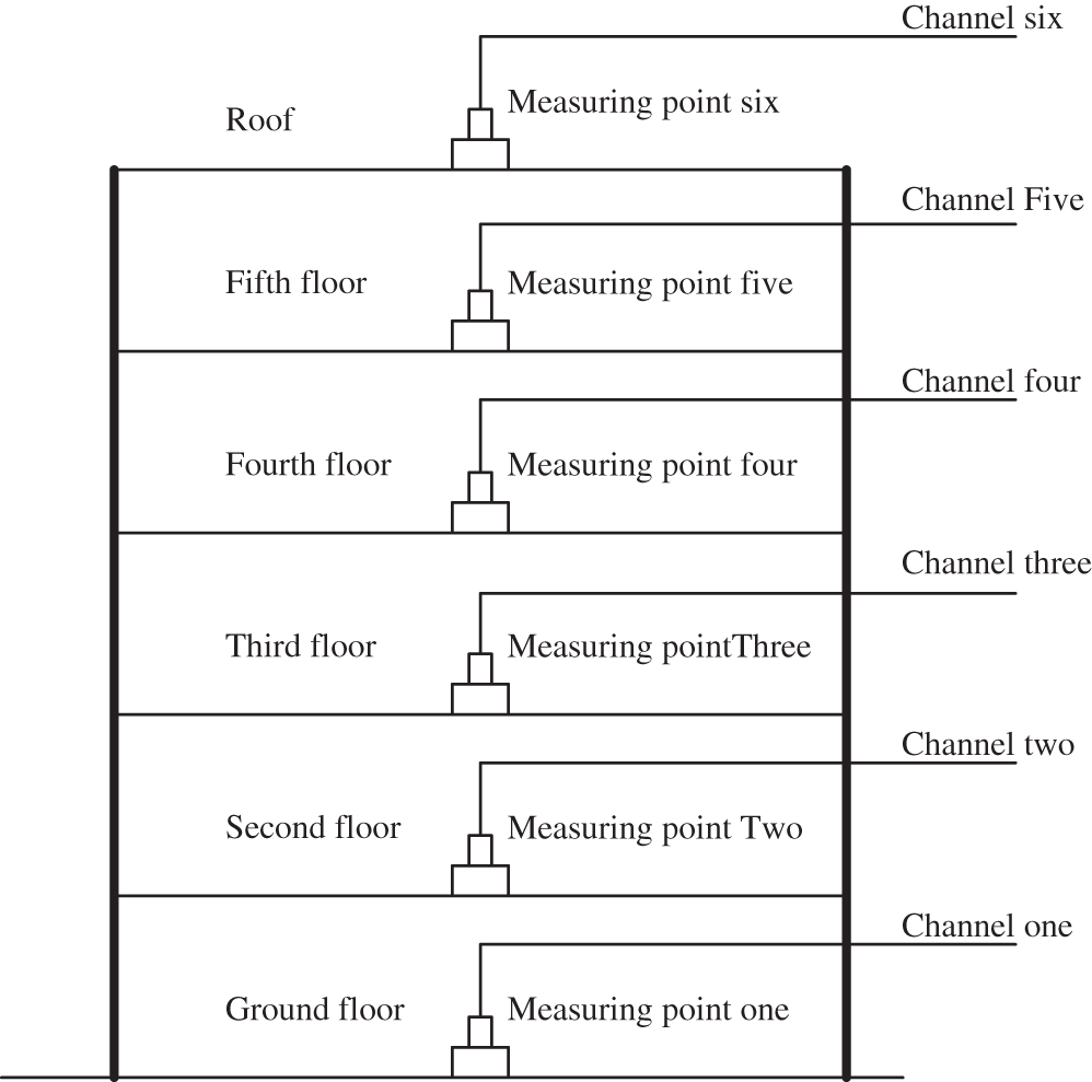
Figure 9: Arrangement graph for each measuring point
The five-floor acceleration time curve is shown as an example in Fig. 10. Fig. 10 shows that the vertical vibration of the five floors was significant before the trench was constructed; the vertical acceleration amplitude was up to 16.67 m/s2. However, the vertical acceleration amplitude of the measuring point was obviously reduced after the trench was constructed. The vertical amplitude vibration acceleration of each measuring point is shown in Table 3.
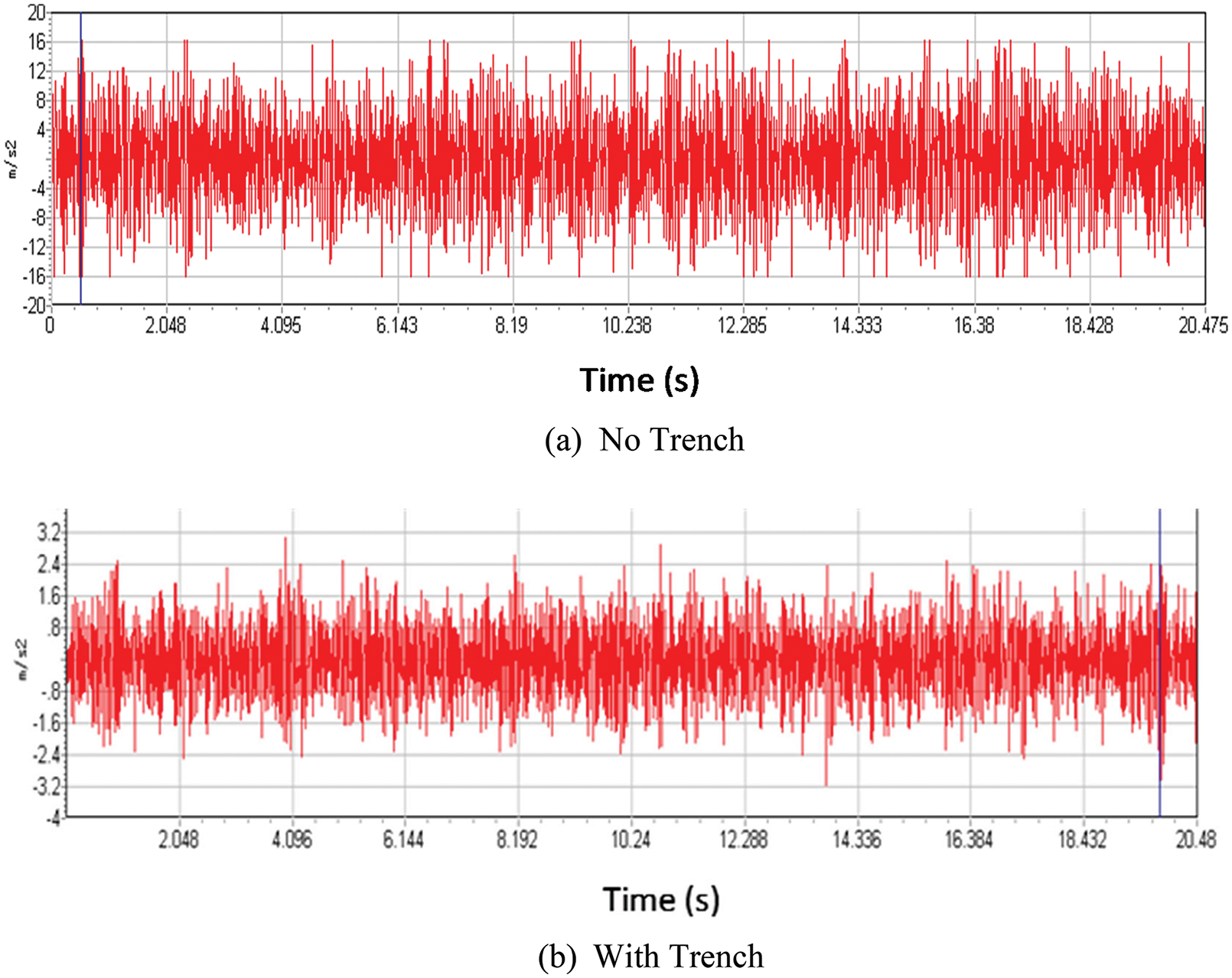
Figure 10: Five-floor acceleration-time curve
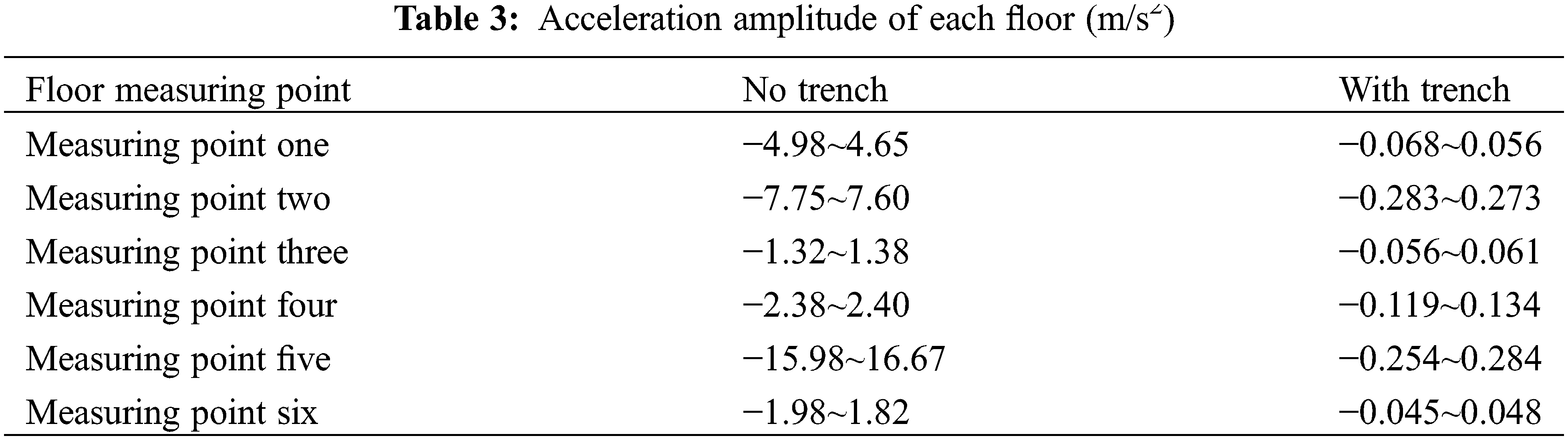
As seen from Table 3, the vertical vibration acceleration amplitudes of the second and fifth floors were significantly large before the trench was constructed but were significantly reduced after the trench was constructed. To define the main energy distribution points of each floor and the vibration of different frequency band attenuations when the trench was constructed, the Fourier transform of the acceleration curve of each floor (the time domain equation is transformed into the frequency domain equation [28–30]) was performed. The Fourier spectrum of the five-story floor is shown in Fig. 11.
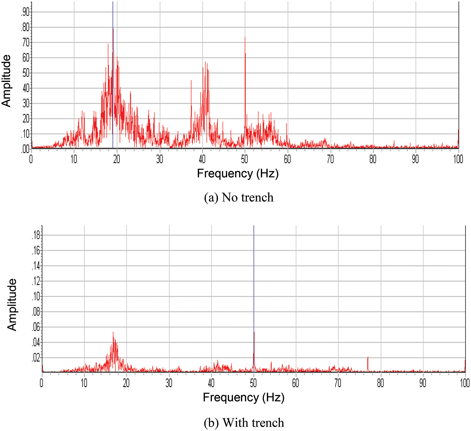
Figure 11: Five-floor frequency spectrum curve
The list of the main energy distribution points of the five-story floor (measuring point 5) and the second floor (measuring point 2) are shown in Table 4.
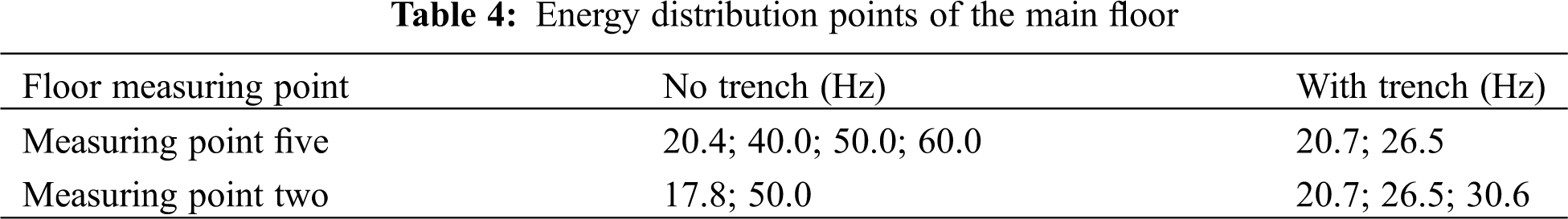
As seen from Table 4, the high-frequency part of the vibration energy of the floor is significantly attenuated, while the low-frequency part of the attenuation is smaller. The 50 Hz energy part of the vibration caused by the surrounding environment was significantly attenuated when the trench was constructed; the vibration wave in the higher frequency part can be effectively reduced by constructing the trench. However, the low-frequency vibration wave cannot be effectively attenuated because of its large wavelength. In this case, the structural vibration caused by the low-frequency wave should be avoided by improving the frequency of the structure.
(1) The depth of the trench is the dominating factor, and the vibration control effect of the trench gradually increases with increasing depth. When the depth of the trench reached 1~1.1 times the wavelength of the Rayleigh wave, the vibration reduction effect was the greatest. However, when the depth is more than 1.3 times the wavelength of the Rayleigh wave, increasing the depth resulted in a reduction of the vibration reduction effect, although the reduction was smaller.
(2) The width of the trench has little effect on the vibration isolation efficiency, and the trench must be maintained at a certain distance from the building to ensure the vibration damping efficiency.
(3) The vibration of each floor of the frame structure was obviously reduced after the trench was built. Using a trench as a vibration reduction measure is especially effective for high-frequency vibration.
(4) The higher frequency part of the vibration wave can be effectively reduced by using the trench method. However, the low-frequency part of the vibration wave cannot be effectively attenuated because of its own large wavelength.
Funding Statement: The research was funded by the National Natural Science Foundation of China (U1904177), Key R&D Projects of the Ministry of Transport (2018-MS5-136), Henan Province Transportation Science and Technology Plan Project (2018J2, 2019J-2-10).
Conflicts of Interest: The authors declare that they have no conflicts of interest to report regarding the present study.
References
1. Barkan, D. D. (1962). Dynamics of bases and foundations. New York: McGraw-Hill Companies. [Google Scholar]
2. Woods, R. D. (1968). Screening of suface waves in soils. Journal of the Soil Mechanics and Foundations Division, 94(4), 951–979. https://doi.org/10.1061/JSFEAQ.0001180 [Google Scholar] [CrossRef]
3. Zou, C., Wang, Y., Zhang, X., Tao, Z. (2020). Vibration isolation of over-track buildings in a metro depot by using trackside wave barriers. Journal of Building Engineering, 30(18), 101270. https://doi.org/10.1016/j.jobe.2020.101270 [Google Scholar] [CrossRef]
4. Haupt, W. A. (1978). Surface waves in nonhomogeneous half-space. In: Dynamical methods in soil and rock mechanics, pp. 335–367. PRANGE. [Google Scholar]
5. Haupt, W. A. (1995). Wave propagation in the ground and isolation measures. Third International Conference on Recent Advances in Geotechnical Earthquake Engineering and Soil Dynamics, Missouri S&T (formerly the University of Missouri--Rolla). [Google Scholar]
6. Bose, T., Choudhury, D., Sprengel, J., Ziegler, M. (2018). Efficiency of open and infill trenches in mitigating ground-borne vibrations. Journal of Geotechnical and Geoenvironmental Engineering, 144(8). https://doi.org/10.1061/(ASCE)GT.1943-5606.0001915 [Google Scholar] [CrossRef]
7. Lei, L., Miao, L., Li, C., Liang, X., Wang, J. (2021). Locally resonant periodic wave barriers for vibration isolation in subway engineering. KSCE Journal of Civil Engineering, 25(4), 1239–1251. https://doi.org/10.1007/s12205-021-1097-3 [Google Scholar] [CrossRef]
8. Eskandarighadi, M., Yarmohammadi, F., Rafiee-Dehkharghani, R. (2022). Vibration isolation of machine foundations by topology optimization of wave barriers. International Journal of Geotechnical Engineering, 16(8), 1–13. https://doi.org/10.1080/19386362.2022.2080946 [Google Scholar] [CrossRef]
9. Venkateswarlu, H., Hegde, A. (2022). Behavior of geocell reinforced bed subjected to vibration loading: Insights from 3D numerical studies. Geosynthetics International, 1–20. https://doi.org/10.1680/jgein.21.00050 [Google Scholar] [CrossRef]
10. Sarkar, A., Barman, R., Bhowmik, D. (2022). Estimation and prediction of screening efficiency of sand crumb rubber (SCR) mix infill trench. International Journal of Geotechnical Engineering, 16(8), 1013–1031. https://doi.org/10.1080/19386362.2021.1964784 [Google Scholar] [CrossRef]
11. Zhou, F., Zhou, Z., Ma, Q. (2022). Study on the vibration isolation performance of an open trench-wave impedance block barrier using perfectly matched layer boundaries. Journal of Vibration and Control, 28(3–4), 329–338. https://doi.org/10.1177/1077546320976962 [Google Scholar] [CrossRef]
12. Kontoni, D. P. N., Farghaly, A. A. (2020). Mitigation of train-induced vibrations on nearby high-rise buildings by open or geofoam-filled trenches. Journal of Vibroengineering, 22(2), 416–426. https://doi.org/10.21595/jve.2019.20523 [Google Scholar] [CrossRef]
13. Surapreddi, S., Ghosh, P. (2022). Experimental and numerical investigations on attenuation response of machine foundations under vertical excitation. Geomechanics and Geoengineering, 17(6), 1865–1886. https://doi.org/10.1080/17486025.2021.1980231 [Google Scholar] [CrossRef]
14. Meng, Q. J., Shi, Z. F. (2018). Propagation attenuation of plane waves in single-phased soil by periodic pile barriers. International Journal of Geomechanics, 18(6), 04018035. https://doi.org/10.1061/(ASCE)GM.1943-5622.0001157 [Google Scholar] [CrossRef]
15. Majumder, M., Bhattacharyya, S. (2021). An alternate arrangement of geofoam blocks and air pocket to mitigate confined blast induced vibration. International Journal of Geotechnical Engineering, 15(1), 52–65. https://doi.org/10.1080/19386362.2019.1698219 [Google Scholar] [CrossRef]
16. Hegde, A., Venkateswarlu, H. (2022). Vibration isolation of foundation systems using geosynthetics barriers. In: Civil engineering for disaster risk reduction, pp. 317–328. Singapore: Springer. [Google Scholar]
17. Jazebi, M., Ahmadi, M. M., Saberian, M., Li, J., Sahebalzamani, P. (2022). Performance of open and in-filled (geofoam) trenches in mitigating ground-borne vibrations induced by impact loading. International Journal of Pavement Research and Technology, 122(110), 1–13. https://doi.org/10.1007/s42947-022-00159-w [Google Scholar] [CrossRef]
18. Zhou, F. X., Liang, Y. W., Ma, Q. (2022). Analysis of the scattering of plane SH waves by multiple open trenches and its vibration isolation performance. Arabian Journal of Geosciences, 15(13), 1–11. [Google Scholar]
19. Al-Jubair, H. S., Ali, J. K., Ajel, H. A. (2021). Finite element analysis of wave barriers used to reduce train induced vibrations. Basrah Journal for Engineering Science, 21(3), 81–89. https://doi.org/10.33971/bjes.21.3.10 [Google Scholar] [CrossRef]
20. Çelebi, E., Fırat, S., Beyhan, G., Çankaya, İ., Vural, İ. et al. (2009). Field experiments on wave propagation and vibration isolation by using wave barriers. Soil Dynamics and Earthquake Engineering, 29(5), 824–833. https://doi.org/10.1016/j.soildyn.2008.08.007 [Google Scholar] [CrossRef]
21. Sivakumar Babu, G., Srivastava, A., Nanjunda Rao, K., Venkatesha, S. (2011). Analysis and design of vibration isolation system using open trenches. International Journal of Geomechanics, 11(5), 364–369. https://doi.org/10.1061/(ASCE)GM.1943-5622.0000103 [Google Scholar] [CrossRef]
22. Kexu, Z., Junfei, X. (1989). Soil dynamics. Beijing, China: Seismological Press. [Google Scholar]
23. Luo, K., Lei, X. (2012). Numerical analysis of railway vibration isolation of new style trenches. Noise and Vibration Control, 2(1), 67–71. [Google Scholar]
24. Liu, J. B., Wang, Z. Y., Du, X. L., Du, Y. X. (2005). Three-dimensional visco-elastic artificial boundaries in time domain for wave motion problems. Engineering Mechanics, 22(6), 46–51. [Google Scholar]
25. Ministry of Housing and Urban-Rural Development of the People’s Republic of China (2010). GB-50011-2010, Code for Seismic Design of Buildings. [Google Scholar]
26. Lei, X. (2006). Analyses of track vibration and track critical velocity for high-speed railway with fourier transform technique. Современные технологии. Системный анализ. Моделирование, 2(7), 59–69. [Google Scholar]
27. Lanmin, W. (2003). Loess dynamics. Beijing, China: Seismological Press. [Google Scholar]
28. Zhang, L. (1992). Vibration testing and dynamic analysis. China: Aviation Industry Press. [Google Scholar]
29. Xu, J. (2002). Building vibration engineering manual. Beijing, China: China Architecture & Building Press. [Google Scholar]
30. Soyoz, S., Taciroglu, E., Orakcal, K., Nigbor, R., Skolnik, D. et al. (2013). Ambient andforced vibration testing of a reinforced concrete building before and after its seismic retrofitting. Journal of Structural Engineering, 139(10), 1741–1752. https://doi.org/10.1061/(ASCE)ST.1943-541X.0000568 [Google Scholar] [CrossRef]
Cite This Article
 Copyright © 2023 The Author(s). Published by Tech Science Press.
This work is licensed under a Creative Commons Attribution 4.0 International License , which permits unrestricted use, distribution, and reproduction in any medium, provided the original work is properly cited.
 Downloads
 Citation Tools