
 Submit a Paper
 Propose a Special lssue
 Open Access
ARTICLE

An Analysis of the Dynamic Behavior of Damaged Reinforced Concrete Bridges under Moving Vehicle Loads by Using the Moving Mesh Technique
Department of Civil Engineering, University of Calabria, Via P. Bucci, Cubo39B, Rende, Cosenza, 87030, Italy
* Corresponding Author: Fabrizio Greco. Email:
Structural Durability & Health Monitoring 2023, 17(6), 457-483. https://doi.org/10.32604/sdhm.2023.030075
Received 01 March 2023; Accepted 15 June 2023; Issue published 17 November 2023
 View Full Text
 Download PDF
Abstract
This work proposes a numerical investigation on the effects of damage on the structural response of Reinforced Concrete (RC) bridge structures commonly adopted in highway and railway networks. An effective three-dimensional FE-based numerical model is developed to analyze the bridge’s structural response under several damage scenarios, including the effects of moving vehicle loads. In particular, the longitudinal and transversal beams are modeled through solid finite elements, while horizontal slabs are made of shell elements. Damage phenomena are also incorporated in the numerical model according to a smeared approach consistent with Continuum Damage Mechanics (CDM). In such a context, the proposed method utilizes an advanced and efficient computational strategy for reproducing Vehicle-Bridge Interaction (VBI) effects based on a moving mesh technique consistent with the Arbitrary Lagrangian-Eulerian (ALE) formulation. The proposed model adopts a moving mesh interface for tracing the positions of the contact points between the vehicle’s wheels and the bridge slabs. Such modeling strategy avoids using extremely refined discretization for structural members, thus drastically reducing computational efforts. Vibrational analyses in terms of damage scenarios are presented to verify how the presence of damage affects the natural frequencies of the structural system. In addition, a comprehensive investigation regarding the response of the bridge under moving vehicles is developed, also providing results in terms of Dynamic Amplification Factor (DAFs) for typical design bridge variables.Keywords
Nomenclature
| B | Width of the bridge |
| BD | Width of the damaged region of the bridge |
| Iv,x | Second moment of area of the vehicle body with respect to the x-axis |
| Iv,y | Second moment of area of the vehicle body with respect to the y-axis |
| L | Length of the bridge |
| LD | Length of the damaged region of the bridge |
| | Longitudinal distance between the center of gravity and the front axle of the vehicle |
| | Longitudinal distance between the center of gravity and the rear axle of the vehicle |
| Mv | Mass of the vehicle body |
| b | Width of the pedestrian lane |
| bL | Base of the longitudinal beam section |
| bT | Base of the transverse beam section |
| bq | Transversal distance between the center of gravity and left/right axle of the vehicle |
| hT | Height of the transverse beam section |
| hL | Height of the longitudinal beam section |
| iL | Longitudinal beam spacing |
| iT | Transverse beam spacing |
| l | Longitudinal distance between the slab edge and the axle of the transverse beam |
| m | Number of longitudinal beams |
| | Mass of the front wheel |
| | Mass of the rear wheel |
| n | Number of transverse beams |
| s | Thickness of the slab |
| ξ | Damage factor |
| | Dynamic amplification factors |
Concrete bridges account for the most diffused infrastructure among highway, railway, and urban transportation networks worldwide [1–3]. In recent years, it is becoming increasingly apparent that several in-service bridge structures are reaching the end of their original design life. In particular, many of these are in a state of degradation because of the adverse effect of dangerous natural agents (e.g., weathering, earthquakes) and severe human-induced actions (e.g., the transit of over-loaded vehicles) [4,5].
The deterioration of material components is of particular concern. As it is well known, concrete suffers from a progressive decline of its mechanical properties because of damage phenomena. Damage phenomena alter the behavior of the bridge, leading to a structure considerably different from that configured during the design phase. Indeed, many studies have highlighted that damage in primary material components changes the structure’s modal properties (i.e., natural frequencies) [6–8]. Besides, damage phenomena introduce local flexibility that negatively impact the response of a bridge under traffic loads because structural deflections increase significantly [9–11].
During the last decades, there has been an urgent need to assess the health status of existing concrete bridges mainly for two leading reasons. First, bridges are a key driver of socioeconomic activities. Unusable or less efficient structures lead to considerable economic losses; second, assessing the vulnerability is vital to avoid safety hazards induced by potential collapse events [12].
Bridge health monitoring has been traditionally conducted through visual inspections. However, the large size of bridge structures and the difficulty of visually inspecting load-bearing members limit the applicability of these methods [13,14]. More refined on-site strategies rely on sensor-based approaches, which consist of installing several sensors on the bridge structure to collect its dynamic response over a certain time. The collected bridge response is subsequently analyzed to assess the bridge conditions, thus detecting the presence, location, and severity of potentially damaged regions [15–18]. In this context, evaluated modal parameters, such as natural frequencies of vibration, natural modes, and modal damping factors, are often adopted as indicators of the levels of structural integrity [19–21]. Through the variations of the modal parameters measured experimentally and using appropriate mathematical models of the structural system, it is possible to ascertain in a non-destructive manner the presence of the damage, its position as well as its level of severity.
However, to be effective, these approaches, usually referred to as “direct methods” of Structural Health Monitoring (SHM), require a considerable number of sensors to be installed on the bridge. Installing many sensors on a bridge structure is often costly. Moreover, it is often an unsafe operation, especially when sensors are placed into critical zones of the structure [22,23].
To overcome the main weaknesses of the direct methods, alternative approaches that identify the bridge status based on the dynamic response of a passing vehicle have been proposed. Specifically, such approaches, known as “indirect methods”, can provide the bridge’s status by processing the dynamic response collected by sensors installed over a vehicle moving on the bridge structure [24–26]. The possibility of identifying the bridge status from the dynamic response of a passing vehicle makes indirect approaches highly attractive for several reasons. First of all, the cheapness. Indeed, indirect methods require fewer sensors than direct ones. Further, the facility of the procedure because dynamic data sampling is straightforward to perform [27,28].
In the framework of indirect methods, numerical models able to reproduce Vehicle-Bridge Interaction (VBI) dynamics represent an essential tool for improving, advancing, and developing such strategies [29–32]. Indeed, most of the studies reported in the literature adopt VBI-based numerical simulations to develop and show the efficiency of the proposed strategies. The main reason relies on the opportunity of setting different damage scenarios, which can be potentially incurred in real applications. Besides, there is the possibility of tuning any of the parameters associated with the bridge structures (e.g., material properties as well as the damage extension and severity) and the moving vehicle.
It should be noted that in order to support the development of SHM, indirect approaches require increasingly reliable and computationally efficient numerical models for reproducing real cases. On the one hand, there is a need to include accurate geometric descriptions for the bridge structures (often formed by articulated geometries) and detailed depictions of damaged regions (i.e., crack patterns). On the other hand, advanced numerical models allow analyzing the behavior of the bridge structure under multiple (even random) traveling vehicles, thus reproducing everyday operative situations.
The analysis of the structural response of a bridge structure under the action of moving loads has been the subject of much research during the last decades [33–35]. In this context, several studies have analyzed the dynamic response of a moving vehicle over a damaged bridge structure [36–38] or just over a damaged beam (see, for instance, [39–41]), proposing different strategies for reproducing damage phenomena. However, many of these studies consist of FE-based numerical investigations (often developed in a two-dimensional setting), which model the structural members through Euler-Bernoulli beam elements. Besides, the adopted transit vehicles are simplified mechanical systems, which are considerably different from real vehicles.
The above simplifications can be justified in view of the computational efforts and complexities associated with numerical models devoted to reproducing VBI problems. Indeed, classic FE-based numerical models developed to simulate VBI problems employ special vehicle-beam elements, in which the degrees of freedom of the vehicle are condensed into those of the beam [42,43]. Such a strategy requires many finite elements to adequately reproduce the interaction phenomena between the vehicle system and the supporting beam, thus involving massive computational efforts in the case of large structures [44]. Besides, the presence of damaged regions in the bridge structure introduces additional complexity to the problem because of the necessity of including special boundary conditions to reproduce local flexibility caused by damage.
To overcome the limitations of the classic FE-based VBI models, as shown in previous author’s works [45,46], an efficient numerical strategy that adopts a moving mesh technique consistent with an Arbitrary Lagrangian-Eulerian (ALE) Formulation has been developed. Precisely, the proposed model consists of moving interfaces that simulate the position of the contact points during the vehicle transit on the bridge structure; this ensures a proper evaluation of the contact forces that account for vehicle-bridge interaction effects. The leading aspect of such an advanced modeling strategy relies on the fact that the bridge structure can be modeled conventionally, thus without the need for special vehicle-beam elements. Besides, it is computationally cheap because there is no need to use refined numerical meshes for the entire computational domain, but only around the domain region of the contact points.
The efficacy of the model proposed by the authors was first assessed in [45] through comparisons with two-dimensional benchmark cases consisting of single-span bridge structures modeled through beam elements. Afterward, the capabilities have also been applied to analyze more general three-dimensional settings in [46] for the vehicle and the bridge structure. In particular, numerical results of 3D straight and curved bridge schemes have been developed, using beam and shell elements for modeling structural members.
However, both studies mentioned above mainly analyzed undamaged bridge structures. The possibility of using the proposed modeling approach also for analyzing the behavior of bridge structures with partially damaged bearing members still needs to be investigated.
This paper proposes an efficient FE numerical model based on the use of ALE formulation for analyzing three-dimensional VBI problems in damaged bridge structures. In particular, this work, which represents an extension of the modeling strategy presented by some of the present authors in [45,46], introduces the following main novelties:
• A refined modeling strategy for the structural members of the bridge structure is adopted by describing longitudinal and transversal beams forming the supporting structure, through solid finite elements, thus providing a more realistic schematization of the structural system; To the authors’ knowledge, such a refined modeling strategy has been scarcely adopted in existing research works available in the literature. In fact, many works propose numerical investigations into a two-dimensional set, in which Euler-Bernoulli beam elements are used for structural elements.
• The use of a moving mesh technique based on the Arbitrarily Lagrangian-Eulerian formulation to accurately trace the position of the contact points between the bridge slab and the vehicle tires, representing an extended version of that proposed in previous Author’s works.
• The presence of damaged regions in the supporting members of the structure (i.e., longitudinal and transversal beams, as well as horizontal slabs); specifically, the model accounts for diffuse damage inside structural elements by a smeared approach consistent with Continuum damage mechanics theory. The leading benefit of such a modeling strategy relies on the fact that the configuration of the damaged zone can be accurately defined since damage develops along longitudinal beams and the afferent portion of the slab, as usually occurs in several practical cases.
Therefore, this paper aims to provide a further contribution to SHM research by proposing an effective numerical tool for supporting the development of more efficient and reliable indirect approaches.
The rest of the paper is arranged as follows: Section 2 reports details on the modeling approach used in the present study. In particular, this section describes the modeling of structural members and damage phenomena, and it provides an overview of the ALE formulation. Section 3 presents the Dynamic Amplification Factors (DAFs) used to quantify the effects induced by the moving vehicle on the damaged bridge structure. Section 4 presents numerical results aimed at assessing the ability of the proposed modeling strategy to simulate the structural response of damaged RC bridge structures. Finally, Section 5 highlights the conclusions of the work also including possible future developments.
Fig. 1 shows a schematic of a single-span Reinforced Concrete (RC) bridge of length L and width B, typically adopted in most road networks worldwide to overcome short-span lengths. The bearing structure consists of m simply supported longitudinal concrete beams, pre-cast or cast-in-place, transversally connected through n stiffening beams.

Figure 1: A schematic view of a single-span Reinforced Concrete (RC) bridge structure
The longitudinal beams have a rectangular section (
The dynamic behavior of a single-span bridge structure largely depends on the degree of integrity of structural members, especially concerning the longitudinal beams. Therefore, reliable predictions of the structural behavior of such structures require (i) adequate schematization of the component members, (ii) refined descriptions of traffic-induced actions, and (iii) valuable strategies to reproduce the degradation of material components. In particular, the latter point represents a leading aspect for reproducing the behavior of existing bridge structures to assess their overall integrity.
To this end, the present study proposes a reliable and efficient numerical model to reproduce the dynamic behavior of damaged single-span RC bridge structures under moving vehicle loads. The sections that follow aim to present the proposed numerical model. In particular, Section 2.1 provides essential information regarding the modeling of the structure components and moving vehicle. Section 2.2 summarizes the ALE formulation adopted in the proposed model to trace the positions of contact points between the bridge’s slab and the vehicle’s tires. These are essential to correctly evaluate the interaction forces defined in the framework of VBI. Finally, Section 2.3 describes the modeling strategy adopted to reproduce structural damage.
2.1 Finite Element Model of the Bridge Structure
The proposed numerical model is implemented within the FE-based commercially available software COMSOL Multiphysics. It consists of three parts: the first is the bridge structure, which includes the main bearing structural elements; the second is a mechanical system schematizing a moving vehicle; finally, the third is an auxiliary computational domain devoted to tracing the position of the contact points between the bridge’s slab and the vehicle’s tires. As introduced previously, the latter component is treated in detail in Section 2.2, while the rest of this section reports information about the bridge structure and moving vehicle implementation.
The bridge structure is idealized by combining plates/shells and three-dimensional solid elements within a three-dimensional setting. In particular, longitudinal and transverse beams are schematized using solid elements, while the deck slab consists of shell elements. Specific kinematic constraints are used to reproduce the rigid mutual connection between the upper boundaries of longitudinal beams and the shell elements schematizing the solid slabs.
The governing equations of the longitudinal and transverse beams of the bridge are the fundamental equations of solid mechanics describing the dynamic equilibrium equation of an infinitesimal three-dimensional solid element. On the other hand, for the shell elements schematizing the slab, the governing equations rely on the thin-plate mechanical model consistent with the Kirchhoff-Love formulation. Both the governing equations of the solids and plate elements are implemented in the FE numerical software in a variational weak form, using the related weak formulations. For brevity, the derivation of the variational forms of solid and shell elements are not reported in the present paper. However, exhaustive details on the topic are available in [46,47].
The moving vehicle consists of a rigid body with four axle sets, each of them comprising a suspension system made of a spring-damper device (Fig. 2).

Figure 2: Generalized dynamic vehicle system. (a) Longitudinal view (b) transverse view
More precisely, the mechanical system of the vehicle comprises an upper sub-system, namely the vehicle body, and a lower sub-system, characterized by the suspension system and tires [48].
With reference to Fig. 2, the displacement range of the mass of the upper body sub-system includes:
• 2 translational components along the vertical (Z) and transverse (Y) directions, respectively, (
• 2 rotation components, with vector axes perpendicular to the X–Z and Y–Z planes, describing the pitch (
In contrast, the displacement field of the i-th mass relative to the lower sub-system comprises only vertical and transverse displacement components for each suspension axis (
The vertical and horizontal relative displacement between the upper end points of the spring-damper systems and the mass of the body vehicle assumes the following form:
For the lower sub-system, the relative displacement between the i-th tire’s mass and the road are expressed as:
where,
The dynamic behavior of the vehicle system is described by the laws of motion derived through Lagrange’s equations of motion as a function of the displacement components and according to the following expression:
in which the terms K, D and Π are the kinetic energy, dissipation potential function, and strain energy of the mechanical system, respectively, equal to:
By substituting the Eqs. (4)–(6) into Eq. (3), the following system of dynamic equilibrium equations is derived in matrix form:
where,
2.2 Fundamentals of the Arbitrary Lagrangian-Eulerian (ALE) Formulation
The ALE formulation is an effective numerical strategy usually adopted to modify the position of the nodes of a two-dimensional computational mesh with great facility while avoiding excessive distortions for the finite elements (see, for instance, [49,50]). The proposed model uses the ALE formulation to move the nodes of computational mesh corresponding to the contact points between the vehicle’s tires and the bridge’s slab. More precisely, the mesh nodes move along the vehicle’s trajectory during the numerical simulation at a constant velocity (c).
To reduce the computational efforts, the proposed model combines two computational domains: the first is that of the bridge structure, in which the solid and shell finite elements are meshed conventionally; the second comprises two parallel lines schematizing the vehicle trajectory on the bridge. This expedient separates the computational meshes so that during the calculation phase, the processed model updates the mesh of the vehicle’s trajectory, without modifying the mesh of the structural elements. The vehicle and bridge domains are linked reciprocally through proper projector functions.
Using the ALE formulation requires the definition of two sets of coordinate systems. The first is the Referential system (
where,
In order to satisfy the previous relations, the mapping function
Fig. 3 shows a representation of the ALE formulation with reference to the case under consideration. The figure depicts the bridge structure and the vehicle crossing with constant speed c, along a travel lane located at a distance ev from the longitudinal centroid axis of the deck. Fig. 3 also shows the contact points between the vehicle and deck in the reference configuration (orange) and in the current configuration (red).

Figure 3: A representation of the use of ALE formulation by the proposed model
Since the reference configuration must be defined at the initial time of the analysis, the structural model of the bridge is enriched by two additional elements schematizing the portions of the ground immediately before and after the deck, with an extension equal to LG.
The two additional portions are implemented as two plates with infinite stiffness, embedded in the ground and disconnected from the bridge slab.
Consequently, their contribution to the numerical calculation model is irrelevant. Their function is exclusively to “house” the vehicle in the initial and final phases of the analysis.
The ALE formulation introduces additional equations to be solved in parallel to those of the structural problem and the vehicle (i.e., Eq. (7)). These are the governing equations of the moving mesh problem and consists of the mesh regularization procedure, based on the solution of the Laplace problem with reference to the displacement of the computational nodes, i.e.:
The Laplace problem is solved by imposing as boundary conditions that the displacements of the computational nodes perpendicular to the traveling direction (nC) and at the end of the moving mesh domain are zero. Furthermore, the speed of the contact points is required to be constant and equal to the speed of the vehicle. By introducing the following nodal mesh displacement function:
The boundary conditions are expressed as follows:
where,
2.3 Modelling of Damage Phenomena
The process of material damage involves the formation and subsequent propagation of a series of defects (such as micro-cracks), which progressively degrade the mechanical characteristics of the material. In existing concrete bridge structures, damage phenomena concentrate inside the most stressed structural regions, thus leading to vulnerable zones where material defects are widespread.
The present investigation adopts an approach consistent with Continuum Damage Mechanics to reproduce the effect of diffuse damage inside circumscribed portions of a structural component. Therefore, the presence of damage is taken into account at the constitutive level by assuming a reduced value of Young’s modulus of the degraded material. In particular, the greater the severity of the damage, the smaller the Young’s Modulus.
The elastic modulus of the material is reduced by a damage factor ξ, which varies from 0 to 1 and defined as follows:
where, ED is the extent of the elastic modulus in the damaged region of the solid (or plate). According to the definition expressed through Eq. (13), the case in which
3 Dynamic Amplification Factors
The structural behavior of a bridge under the action of moving loads is typically analyzed in terms of Dynamic Amplification Factors (DAFs). The most common definition of DAF (
From Eq. (14), it emerges that
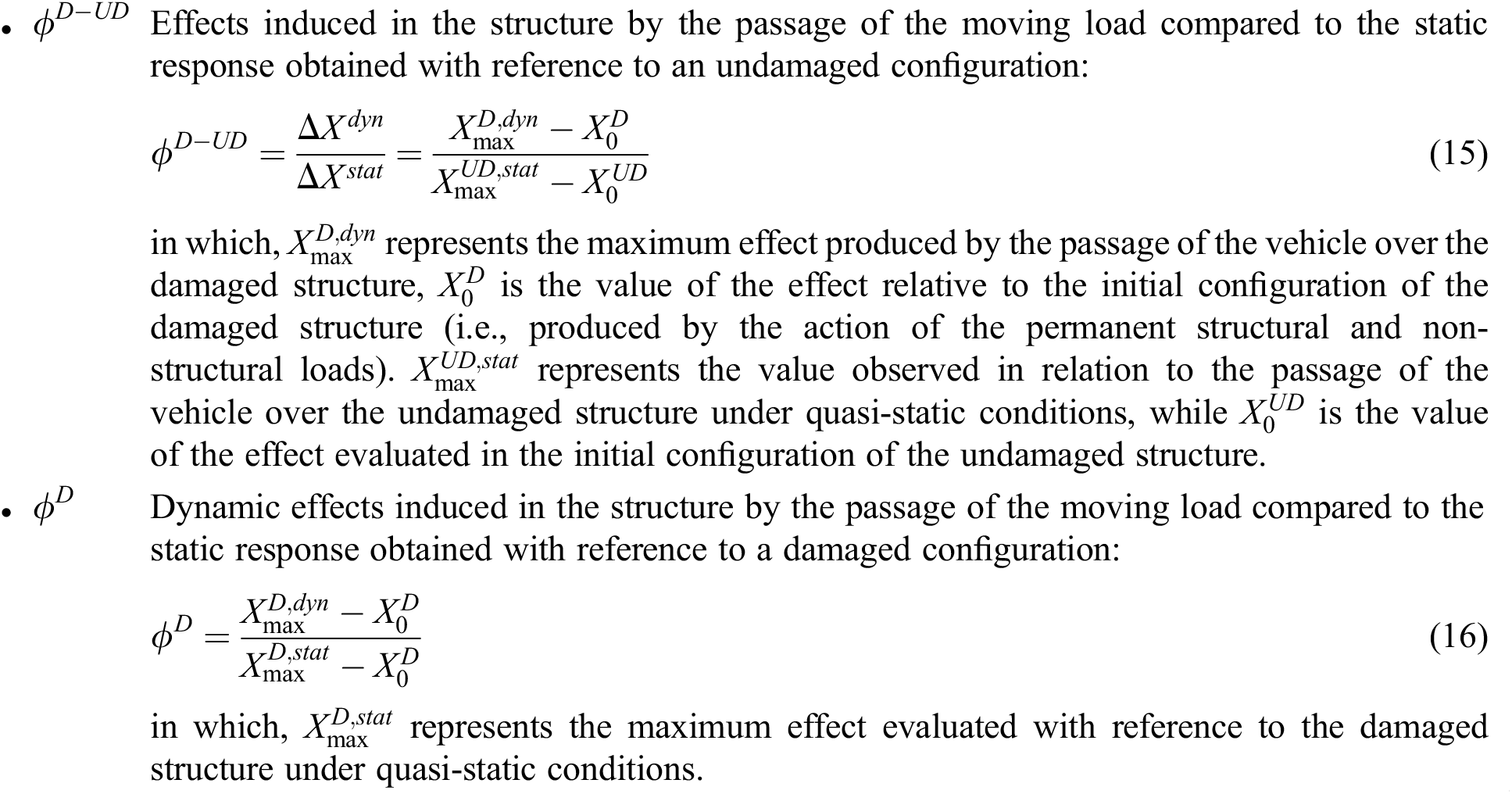
DAFs are typically calculated for intact structures, therefore, without considering the presence of damaged regions inside structural members. Using amplification factors for partially damaged bridge structures requires some preliminary considerations. Indeed, a partially damaged structure’s response differs considerably from an intact one’s. To clarify this concept, Fig. 4 compares the time histories of the mid-span vertical displacement of an undamaged and damaged single-span bridge subject to permanent (structural and non-structural) and moving vehicle loads. In particular, the damage is assumed to occur around the mid-span region.

Figure 4: Time history of vertical displacement of the midspan of a single-span bridge subject to moving loads: comparison of damaged and undamaged structure
Twofold observations can be outlined. First, the presence of the damage affects the configuration of the structure already under the action of permanent loads. In fact, a greater initial deflection (
From the abovementioned considerations, two sets of DAFs should be used to comprehensively describe the dynamic behavior of a damaged bridge structure under moving vehicle loads. One DAF should quantify the amplification of the effects concerning the undamaged configuration. The other serves to quantify the amplification effects induced in the damaged structure by the moving vehicle loads. Therefore, the following DAFs are utilized in the present study:
For the sake of completeness, the DAF for the intact structure (i.e.,
This section reports comprehensive results to show the proposed model’s efficiency and flexibility in simulating the behavior of damaged Reinforced Concrete (RC) bridge structures. More precisely, the results concern a numerical investigation developed regarding a typical single-span bridge scheme adopted in most of the main roadways of the Calabria Region (Italy). To this end, Section 4.1 describes the geometry of the examined bridge structure, the damage scenarios considered, and the moving vehicle selected to reproduce the traffic-induced actions. In addition, this sub-section describes the mesh discretization adopted in the numerical model. Afterward, numerical results are reported. In particular, the proposed study comprises two numerical investigations. The first, reported in Section 4.2, analyzes the bridge structure’s behavior affected by damaged regions presence without considering the effects of moving vehicle loads. Specifically, such an analysis aims to examine the variations of the modal characteristics of the structural system (i.e., natural vibration frequencies and corresponding mode shapes) caused by the damage phenomena, thus assessing the efficacy of the modeling strategy presented in Section 2.3 to account for the damage presence inside structural elements.
The second, reported in Section 4.3, focuses on the bridge’s structural response because of the simultaneous presence of damage and a moving vehicle. The primary aim is to show the ability of the proposed VBI modeling strategy based on the ALE formulation to simulate the dynamic response of damaged bridge structures. However, a detailed validation was developed in previous author’s works [43].
4.1 The Case of Study: The Geometry, the Loads, and the Damage Scenarios
To properly configure a realistic scheme of an existing single-span RC bridge, a preliminary investigation has been conducted by analyzing over 20 existing bridge structures of variable span lengths built in the Region of Calabria in the last few decades. The primary aim is to collect sufficient data to define acceptable ranges of values for the dimensions of the bearing elements of the structure.
Table 1 reports the results of such a preliminary analysis. As one can see, the data are arranged in three groups, which differ reciprocally according to the span length. In particular, Group 1 summarizes the ranges of values for existing bridge structures with a span length from 30 to 35 m, whereas Groups 2 and 3 represent bridge structures with span lengths ranging between [25 ÷ 29] meters and [20 ÷ 24] meters, respectively.

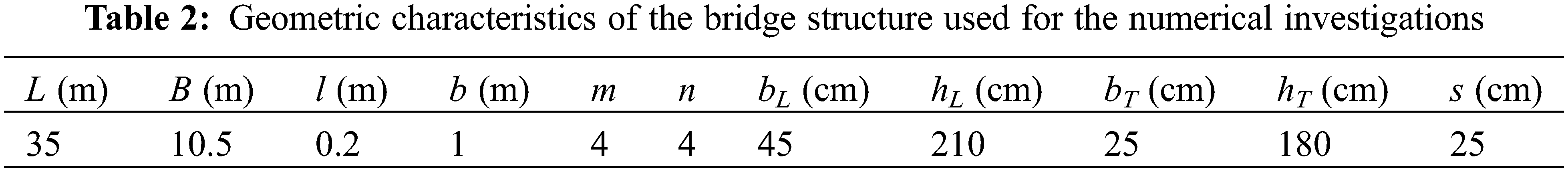
The bridge structure adopted in the present investigation belongs to the Group 1 of Table 1. More precisely, the structure’s geometry consists of four longitudinal beams of length L = 35 m connected transversally through four stiffening beams, equally spaced from each other of
The longitudinal and transverse stiffening beams support a slab of length L = 35 m, width B = 10.5 m, and thickness s = 25 cm. The slab includes several vehicle lanes and two outer cantilevered pedestrian passages of width b = 1 m. In particular, the distance between the longitudinal axes of the two end beams is equal to 8.5 m. Table 2 summarizes the bridge dimensions.
The longitudinal and transversal beams, and the slabs are made of concrete, whose Young’s Modulus, Poisson’s ratio and mass density are equal to E = 30 GPa, ν = 0.3, and ρ = 2500 kg/m3, respectively.
The bridge is subjected to the actions induced by the self-weight of the structural elements and additional permanent loads. In particular, the permanent load consists of a layer of 7 cm asphalt (ρa = 1300 kg/m3), considered in terms of both additional weight and mass.
Concerning the accidental loads, it is assumed that one vehicle crosses the bridge at constant speed along a single roadway eccentrically placed regarding the longitudinal axes of the deck at a distance of 2.8 m (i.e., y = −2.8, see Fig. 1). Table 3 summarizes the geometric and mechanical properties of the considered vehicle, which are identical to that reported in [48].

Fig. 5 shows the numerical model used in numerical simulations. As one can see, it comprises (i) the bridge structure, (ii) two moving interface edges (marked in red), and (iii) two additional side regions (colored in light blue) placed at the beginning and the end of the structure, which serve as auxiliary areas to account for the entry and exit of the vehicle along the bridge. Therefore, they are not connected to the bridge and are modeled as a rigid material. The geometry of the bridge structure is discretized using a fine regular-type mesh.

Figure 5: Computational mesh adopted in numerical simulations
Noting that a preliminary analysis was developed to identify the optimal size of the finite elements for defining an acceptable compromise between computational efforts and the accuracy of numerical results. From such a preliminary mesh sensitivity analysis, it results that a suitable discretization for the geometry domain of the structure is that made of linear parallelepipeds (8 nodes) with a maximum side length of 20 cm for the beams (39,096 elements) and linear quad elements (4 nodes) of side 40 cm for the shells corresponding to the slab (2,340 elements). In contrast, the plates corresponding to the side regions are discretized through a coarse mesh made of rectangular elements with a maximum size of 1.2 m (36 elements). Unlike the geometry of the bridge structure, the mesh of moving interfaces is quite fine near the contact points between the bridge’s slabs and vehicle wheels and relatively coarser elsewhere. This choice is motivated because the ALE formulation does not require fine discretization for the entire domain, but only in the zone of particular interest. Besides, the mesh of moving interfaces moves consistently with the vehicle speed.
The present investigation examines several damage scenarios, for which the damage mainly affects the structure’s center region. Specifically, the assumed damage scenarios differ reciprocally depending on the damage level and extension at the bridge’s mid-span region (Fig. 6). In particular, it is assumed that the damage region extends along the longitudinal direction according to the dimensionless length LD/L. In contrast, in the transverse direction, the damage extension is measured by the dimensionless length BD/B, and it involves an increasing number of longitudinal beams (comprising the afferent portion of the slab) (see Fig. 6). Besides, within the damaged regions, the severity of damage is constant and expressed through the parameter

Figure 6: Representation of a damage scenario for the examined bridge structure
• Damage scenario 1 (DS1): a single damaged longitudinal beam and the afferent portion of the slab, considering the entire cantilevered portion (BD/B = 0.25);
• Damage scenario 2 (DS2): two damaged longitudinal beams and the afferent portion of the slab, considering the entire cantilevered portion (BD/B = 0.50);
• Damage scenario 3 (DS3): three damaged longitudinal beams and the afferent portion of the slab, considering the entire cantilevered portion (BD/B = 0.75);
• Damage scenario 4 (DS4): diffuse damage in all longitudinal beams, including the entire slab (BD/B = 1.00).
It is worth noting that the influence of damage in transversal beams was investigated with a specific analysis, referred, for the sake of brevity, only to the damage scenario DS3.
4.2 Influence of Damage Effects on the Modal Characteristics of the Structure
At first, the investigation examines the variations of the modal characteristics of the structure caused by the damage phenomena. Therefore, the effects induced by moving vehicles are not considered.
Fig. 7 compares the natural frequencies and the corresponding mode shapes evaluated for the intact structure (i.e., undamaged, referred to as UD) and a bridge configuration affected by a DS2-type damage scenario (D) (i.e., BD/B = 0.5). In particular, the damage scenario involves two longitudinal beams and the afferent portion of the slab for an extension LD/L = 0.5 and a damage severity of ξ = 0.5. Note that the analysis focuses only on the frequencies corresponding to vertical bending (symmetrical and anti-symmetrical) and the torsional natural mode shapes. This choice is motivated by the fact that these natural mode shapes typically dominate the dynamic response of three-dimensional simply supported structures. Therefore, they are the most efficacy in highlighting the effects of the assumed damage scenario.

Figure 7: The vertical bending (symmetrical and anti-symmetrical) and the torsional mode shapes for the examined bridge structure: A comparison between the intact structure (UD) and a bridge configuration affected by a damage scenario involving two longitudinal beams and the afferent portion of slab for LD/L = 0.5 and BD/B = 0.5, and a damage severity of ξ = 0.5
The results show that the presence of damage inside a limited portion of the mid-span region of the bridge structure does not significantly alter the natural modal shapes. Indeed, no significant differences exist between the natural mode shapes corresponding to the undamaged and damaged structures. Such a result allows for easy identification of similar mode shapes. In contrast, one observes that the frequencies of the damaged bridge are lower than that of the intact structure. In particular, the reduction is about 23.57%, 15.34%, and 11.64%, for the symmetrical vertical, anti-symmetrical vertical, and torsional mode shapes, respectively. Such results are in line with the outcomes reported in [51–53] which examined the variations of the modal characteristic of damaged RC beams because of flexural cracking (i.e., generated by four-point or three-point bending tests). In particular, these studies report that the main frequencies of the beam (i.e., those associated with the symmetrical and anti-symmetrical vertical bending mode shapes) drastically reduce as the damage increases both in terms of extension and severity. For example, Hamad et al. [52] have investigated the vibration properties of many RC beams damaged through four-point bending tests experimentally and numerically. In particular, they have conducted several analyses considering various levels of damage inside the beam, each caused by increasing values of the applied static forces. Their results show that the maximum reduction of the natural frequency corresponding to the first four mode shapes reaches a value of about 12% (a value associated with the complete failure of the beam). Casas et al. [53] performed damage-identification analyses on RC beams with different, well-defined damage patterns.
In particular, the results achieved for the beams with damage located at the mid-span have revealed that the frequency reduction of the symmetrical vertical bending mode shape ranges between 18% and 21%, depending on the damage’s extension and severity.
A detailed study is now conducted to analyze further the bridge structure’s behavior for different damage configurations. More precisely, the investigation comprises three parametric analyses for which the variations of the natural frequencies corresponding to the vertical bending (symmetrical and anti-symmetrical) and torsional mode shapes are evaluated by varying the severity, the longitudinal (LD/L) and transversal (BD/B) extensions of the damaged region (i.e., for all damage scenario considered). To effectively quantify the variation, the following dimensionless frequency variation variable is introduced.
where,
Figs. 8a–8c show the variation of

Figure 8: Variation of normalized reduction of the natural frequencies (Δf) of the bridge structure associated with the vertical bending (symmetrical and anti-symmetrical) and torsional mode shapes for different damage scenarios: (a) Evolutions for increasing values of the damage severity considering damage scenario with LD/L = 0.5 and BD/B = 0.5. (b) Variability as a function of the longitudinal extension (LD/L) of the damage in two longitudinal beams (DS2-type damage scenario, BD/B = 0.5), assuming ξ = 0.5. (c) Effect of the transversal extension of the damaged region fixing LD/L = 0.5 and ξ = 0.5
Fig. 8b presents the results aimed at highlighting the influence of the longitudinal extension of the damaged region (i.e., for increasing values of LD/L) on the behavior of the structure. In particular, the damage affects two longitudinal beams only with a severity equal to ξ = 0.5. Finally, Fig. 8c focuses attention on the effect caused by the transversal extension of the damaged region (i.e., by varying BD/B). Such a figure illustrates the trend of
The results denote that all the examined natural frequencies manifest a reduction trend as the damage inside the structure increases (both in terms of damage severity and extension). In such a context, Fig. 8a clearly denotes that the damage severity (i.e., ξ) considerably affects the response of the bridge. Indeed, the maximum reductions for Δf occur for increasing values of ξ. In particular, the maximum reduction of the natural frequencies corresponding to the symmetrical vertical bending, torsional and anti-symmetrical vertical bending modes shapes are equal to 37%, 18%, and 25%, respectively. As expected, the frequency corresponding to the symmetrical vertical bending mode shape suffers from the maximum reductions because the damage affects the mid-span of the bridge, thus significantly influencing the overall behavior of the structure, especially concerning the bending stiffness of longitudinal beams.
Twofold observations can be outlined regarding the influence of the extension of the damaged region inside the bridge structure. The longitudinal extension (investigated by varying the dimensionless length LD/L) produces a limited reduction of Δf for the examined frequencies (see Fig. 8b). However, by observing the zoomed view of Fig. 8b, one observes a non-linear decrement of Δf corresponding to the anti-symmetrical vertical bending mode shape. In particular, Δf considerably decreases for values of LD/L larger than 0.3. This result can be motivated by the fact that as the damage zone extends longitudinally, the side portion of the bridge (i.e., the zones at x = L/4 and x = 3/4L) suffers from progressively stiffness losses, which inevitably affect the values of vertical anti-symmetrical frequency. Like the longitudinal extension, the transversal increment of the damage region slightly affects the response of the bridge (see Fig. 8c). However, the reduction of Δf associated with the torsional mode shape manifests a notable non-linear trend (see the zoomed view), for which a more significant decrement manifest once the damage transversally involves all the longitudinal beams (i.e., BD/B = 1–DS4). This condition is likely to produce a considerable reduction of the overall torsional stiffness of the bridge, thereby affecting the values of the associated natural frequency.
It is worth noting that the previous parametric investigation assumes that the transversal stiffening beams are perfectly intact. Then, additional detailed analyses are performed to analyze the influence of damaged transversal beams on the bridge’s structural response.
The analysis refers to damage scenario 3 (DS3) and focuses only on the frequency associated with the torsional mode because the transversal beams mainly influence the torsional stiffness of the structure. Fig. 9 compares the variations of frequency for the torsional mode for different extensions of the damaged region (LD/L) and increasing values of the damage severity (ξ). In particular, for the same bridge structure, the figure compares the results associated with undamaged (case 1) and damaged (case 2) transversal beams to better highlight the effect induced on the structural response by the presence of the damage also in the transversal beams.

Figure 9: Influence of the damaged transverse beams on the variation of the modal characteristics of the structure. (a) Comparison of damage cases relative to damage scenario 3. (b) Variation of the natural frequency relative to the torsional mode shape for different values of LD/L and ξ
The results show that the damage in the transverse beams does not significantly produce frequency variations. Indeed, the curves report comparable values of frequency variations for any value of LD/L and ξ considered. Consequently, it can be assumed that the most significant structural frequency variations occur because of damaged longitudinal beams and the afferent portion of slab.
4.3 Analysis of Structural Response of the Damaged Bridge Structure under the Action of Moving Loads
This section aims to examine the structural response of the bridge structure affected by damage phenomena under the actions induced by a two-axle vehicle, whose properties are summarized in Table 3. Although road roughness may represent an important factor in the interaction response between the bridge and the vehicle (as demonstrated in [54,55]), in the present study the analysis has been conducted under the simplified hypothesis of smooth conditions for the road pavement of the bridge, since the main attention is devoted to investigate the effects of the damage on the bridge dynamical behavior under moving loads.
At first, the behavior of the structure is investigated concerning a DS2-type (i.e., BD/B = 0.5) damage scenario (described in Section 4.1) based on a longitudinal extension for the damaged region at bridge mid-span of LD/L = 0.5 and a damage severity equal to ξ = 0.55. Fig. 10 compares the evolution of the dimensionless mid-span vertical displacement (

Figure 10: Time histories of the vertical displacement of the mid-span point of the longitudinal beam placed at y = −4.475 m for different vehicle transit speeds. A comparison between the response of the intact structure (UD) and a damaged configuration of the bridge consistent with a DS2-type damage scenario, developing along the mid-span of the bridge for an extension of LD/L = 0.5 and characterized by a damage severity of ξ = 0.55
In particular, the figure reports the results for the traveling speeds of the vehicle of 40, 80, and 120 km/h, which can be considered representative of the ranges of low, medium, and high transit speeds. From the results, it transpires that the considered damage scenario (i.e., DS2-type) produces a considerable increment of the vertical deflection of the structure, already under the action of permanent loads only. As one can see, the increment of the vertical deflection because of damage is about 47% (see the dashed lines at
The action induced by the vehicle produces additional increments of the vertical displacement. In this framework, the transit speeds considered generate almost comparable deflections. In particular, by referring to the results corresponding to the transit speed of 80 km/h (marked by the red line), the increment of deflection produced by the moving vehicle and associated with the damaged structure (
To better highlight the effects induced into the structure by the moving vehicle, the results achieved for the transit speeds of 40, 80, and 120 km/h are further investigated by examining the dimensionless deflection increment
in which, vp+v and vp represent the deflection produced by the simultaneous action of permanent and moving loads and permanent loads only, respectively.
Figs. 11a–11c show the time-histories of

Figure 11: Time history and frequency content of
Table 4 reports the values of natural frequencies corresponding to the first vertical bending (symmetrical and anti-symmetrical) and torsional mode shapes concerning the intact structure and the DS2-type damage scenario (i.e., BD/B = 0.5) considered.

The results denote that the vehicle-induced vibrations are relatively small for moderate transit speeds (i.e., c = 40 km/h). Such a condition is confirmed by the results expressed in the frequency domain, where one observes that the frequency content diverges from the natural frequencies for both the intact and damaged bridge structures.
Nevertheless, even though the vibrations are globally small, it is worth noting that the presence of damage along the mid-span of the bridge causes a remarkable increment of the oscillation amplitudes, precisely about 70%.
Next, by referring to the results for the vehicle transit speed of 80 km/h (reported in Fig. 11b), the results show that the intact and damaged structures suffer from relevant dynamic amplification effects. Such behavior is likely to be relayed to the occurrence of resonance conditions affecting both undamaged and damaged bridge structures. Indeed, the results reported in the second of Fig. 11b reveal that the frequency content of vehicle-induced displacements matches the natural frequency corresponding to the first symmetrical vertical bending mode shape for both intact and damaged bridge structures. In addition, what is interesting about the data in this figure is that the presence of the damage causes a considerable increment of vibrations, which can negatively affect the structure’s integrity. The results achieved by assuming a traveling speed of 120 km/h (Fig. 11c) reveal that the vehicle’s passage does not induce relevant vibrations into the structure. Such a condition finds confirmation in the results expressed in the frequency domain, which highlights that the peaks of frequency contents do not match the values of natural frequencies corresponding to the intact and damaged bridge structures. However, dynamic amplification effects manifest in the form of a global increment of the maximum deflection. In particular, a comparison between the traveling speeds of 40 and 120 km/h indicates an increment of the maximum deflection of about 4%.
Further results are proposed concerning the response of the moving vehicle, thus providing additional insights into damage-induced effects on the behavior of the mechanical system and, in turn, on the travelers’ comfort. Figs. 12a–12c show the vertical accelerations of the vehicle for transit speeds of 40, 80, and 120 km/h, respectively. Besides, each figure compares the results achieved for the intact and the damaged structure. As expected, the resonance condition occurring for c = 80 km/h affects considerably also the vehicle’s response because the gained vertical accelerations are generally higher than that achieved for 40 km/h. In particular, regarding the intact structure, the maximum acceleration value for c = 80 km/h is higher than that obtained for c = 40 km/h by 150%. Surprisingly, the vehicle reaches significant acceleration values for the transit speed of 120 km/h, even though the bridge structure is unaffected by significant vibrations (as observed previously in Fig. 11c). The results reveal that the damage also negatively affects the overall response of the vehicle, increasing the entity of the vertical acceleration. Such a trend is quite evident in the results achieved at the transit speeds of 80 and 120 km/h, where the increment of the absolute acceleration values is about 28% and 26%, respectively.

Figure 12: A comparison in terms of vertical acceleration of the moving vehicle on the undamaged (UD) and damaged (D) bridge structures. Vehicle speeds of (a) 40 km/h; (b) 80 km/h; (c) 120 km/h
Finally, the behavior of the structure is analyzed in terms of Dynamic Amplification Factors (DAFs), as introduced in Section 3. In particular, a comprehensive investigation is performed, providing the variation of the DAFs for different traveling speeds of the vehicle and all damage scenarios considered (i.e., DS1, DS2, DS3, and DS4). Figs. 13a–13c show the evolution of DAFs (i.e.,

Figure 13: Evolution of the dynamic amplification factors
In particular, Fig. 13a shows the evolution of
The results reveal that the intact structure suffers from dynamic amplification of the vertical mid-span displacement, whose maximum value (i.e.,
The damage phenomena inside the structure produce an overall increment of dynamic amplification effects. Starting from the results gained for
Because of such variations in the mechanical properties of the materials of the structure, it is probable that resonance conditions do not occur, thus avoiding peaks of values of
By observing the curve associated with the factor
This observation reflects the evolution of
This work has presented an effective FE numerical model capable of accurately reproducing the behavior of damaged Reinforced Concrete (RC) bridge structures under vehicle moving loads. The proposed numerical model is developed in a three-dimensional setting, thus allowing reliable representations of the structural geometry. Besides, it adopts a moving mesh technique, consistent with the Arbitrary Lagrangian-Eulerian (ALE) formulation, to trace accurately the positions of the contact points between the vehicle’s tires and the bridge’s slab during the simulation. The study has analyzed the response of a conventional RC single-span bridge structure, performing two sets of numerical results.
The first set is focused on the behavior of the bridge structure because of the effects induced by the damage phenomena only, thus without considering the actions of moving vehicles. In particular, such a study aimed to evaluate the variation of the modal characteristic of the bridge structure (i.e., natural frequencies and corresponding mode shapes) caused by the damage. The results have revealed that damage phenomena mainly alter the values of the structure’s natural frequency. In particular, all the investigated natural frequencies reduce strictly depending on the severity of the damage and the extension of the damaged region inside the bridge structure. In such a context, the results have shown that the damage severity represents a leading factor in the response of the damaged bridge. Indeed, the maximum decrements of natural frequencies of the structure were associated with the maximum entities of the damage’s severity.
The second set of results is devoted to analyze the dynamic response of the damaged bridge structure under moving vehicle loads. The results have shown that damage negatively affects the structural behavior of the bridge also in presence of permanent loads only, leading to initial deflections much greater than that related to the undamaged structure. This behavior occurs since the damage causes local reduction of the stiffness in the longitudinal beams. Starting from the initial deflections of the structure, a moving vehicle induces dynamic vibrations, whose amplitude varies according to the traveling speed. In particular, for medium traveling speeds, resonance phenomena affect the response of the investigated bridge structure, both for undamaged and damaged configurations. However, the damaged structure suffers higher amplification under resonance conditions than the intact case. Finally, the analysis of the structure in terms of Dynamic Amplification Factors (DAFs) has indicated that damage phenomena produce an overall increment of amplification effects for any traveling speed of the investigated vehicle. In particular, the DAFs assume significant values (larger than those associated with the intact structure) for increasing values of the damage severity.
In conclusion, due to its accuracy and completeness, the proposed model can be adopted as suitable tool for the development of indirect methods in the framework of Structural Health Monitoring (SHM) approaches.
As a possible direction for future investigations, it would be interesting to improve the capability of the proposed model by implementing more refined schematization for the damaged zone inside the structure and to analyze the influence of road conditions on the response of damaged bridge structures. More precisely, the damage could be reproduced more reliably using advanced modeling strategies developed in the framework of fracture mechanics, such as those consistent with the recent diffuse cohesive interface approaches (see, for instance, [56]) or the phase field method [57–59]. Moreover, road roughness may play a significant role in the interaction behavior between the vehicle and the bridge, as shown for instance in [54–55,60].
Acknowledgement: Paolo Lonetti, Arturo Pascuzzo and Giulia Sansone gratefully acknowledge financial support from the Italian Ministry of University and Research (MUR) for the Research Grant on “Opportunities and Challenges of Nanotechnology in Advanced and Green Construction Materials”.
Funding Statement: This research was supported by Ministry of University and Research (MUR) through the Research Grant “PRIN 2020 No. 2020EBLPLS” and “Programma Operativo Nazionale (PON) 2014–2020”.
Author Contributions: The authors confirm contribution to the paper as follows: study conception and design: Fabrizio Greco, Paolo Lonetti; methodology: Arturo Pascuzzo, Giulia Sansone; analysis and interpretation of results: Arturo Pascuzzo, Giulia Sansone; data curation: Giulia Sansone, writing-original draft: Paolo Lonetti, Giulia Sansone; writing-review & editing: Fabrizio Greco, Paolo Lonetti, Arturo Pascuzzo; supervision: Fabrizio Greco, Paolo Lonetti, Arturo Pascuzzo. All authors reviewed the results and approved the final version of the manuscript.
Availability of Data and Materials: To access the data used in the study, it is possible to contact the corresponding author.
Conflicts of Interest: The authors declare that they have no conflicts of interest to report regarding the present study.
References
1. Zhang, B., Qian, Y., Wu, Y., Yang, Y. B. (2018). An effective means for damage detection of bridges using the contact-point response of a moving test vehicle. Journal of Sound and Vibration, 419, 158–172. [Google Scholar]
2. Tan, C., Zhao, H., Uddin, N., Yan, B. (2022). A fast wavelet-based bridge condition assessment approach using only moving vehicle measurements. Applied Sciences, 12(21), 11277. [Google Scholar]
3. Sun, Z., Nagayama, T., Nishio, M., Fujino, Y. (2018). Investigation on a curvature-based damage detection method using displacement under moving vehicle. Structural Control Health Monitoring, 25(1), e2044. [Google Scholar]
4. Zhu, J., Zhang, Y. (2023). Damage detection for bridge structures under vehicle loads based on frequency decay induced by breathing cracks. Structure and Infrastructure Engineering, 19(6), 793–809. [Google Scholar]
5. Xu, H., Liu, Y. H., Wang, Z. L., Shi, K., Zhang, B. et al. (2022). General contact response of single-axle two-mass test vehicles for scanning bridge frequencies considering suspension effect. Engineering Structures, 270, 114880. [Google Scholar]
6. Liu, C., Zhu, Y., Ye, H. (2023). Bridge frequency identification based on relative displacement of axle and contact point using tire pressure monitoring. Mechanical Systems and Signal Processing, 183, 109613. [Google Scholar]
7. Yang, Y. B., Yang, J. P. (2018). State-of-the-art review on modal identification and damage detection of bridges by moving test vehicles. International Journal of Structural Stability and Dynamics, 18(2), 1850025. [Google Scholar]
8. Lieven, N. A. J., Ewins, D. J., Farrar, C. R., Doebling, S. W., Nix, D. A. (2001). Vibration–based structural damage identification. The Royal Society, 359(1778), 131–149. [Google Scholar]
9. Lu, N., Ma, Y., Liu, Y. (2019). Evaluating probabilistic traffic load effects on large bridges using long-term traffic monitoring data. Sensors, 19(22), 5056. [Google Scholar] [PubMed]
10. Lu, N., Beer, M., Noori, M., Liu, Y. (2017). Lifetime deflections of long-span bridges under dynamic and growing traffic loads. Journal of Bridge Engineering, 22(11), 04017086. [Google Scholar]
11. Mao, J. X., Wang, H., Feng, D. M., Tao, T. Y., Zheng, W. Z. (2018). Investigation of dynamic properties of long-span cable-stayed bridges based on one-year monitoring data under normal operating condition. Structural Control Health Monitoring, 25(5), e2146. [Google Scholar]
12. Sun, S., Sun, L., Chen, L. (2016). Damage detection based on structural responses induced by traffic load: Methodology and application. International Journal of Structural Stability and Dynamics, 16(4), 1640026. [Google Scholar]
13. Cha, Y. J., Buyukozturk, O. (2015). Structural damage detection using modal strain energy and hybrid multiobjective optimization. Computer-Aided Civil and Infrastructure Engineering, 30(5), 347–358. [Google Scholar]
14. Omenzetter, P., William Brownjohn, J. M. (2006). Application of time series analysis for bridge monitoring. Smart Materials and Structures, 15(1), 129. [Google Scholar]
15. Salawu, O. S. (1997). Detection of structural damage through changes in frequency: A review. Engineering Structures, 19(9), 718–723. [Google Scholar]
16. Doebling, S. W., Farrar, C. R., Prime, M. B. J. T. S., Digest, V. (1998). A summary review of vibration-based damage identification methods. Shock and Vibration Digest, 30, 91–105. [Google Scholar]
17. Magalhães, F., Cunha, A., Caetano, E. (2012). Vibration based structural health monitoring of an arch bridge: From automated OMA to damage detection. Mechanical Systems and Signal Processing, 28, 212–228. [Google Scholar]
18. Edwins, D. J. (2009). Modal testing: Theory, practice and application. Hoboken: Wiley. [Google Scholar]
19. He, K., Zhu, W. D. (2011). Structural damage detection using changes in natural frequencies: Theory and applications. Journal of Physics: Conference Series, 305(1), 012054. [Google Scholar]
20. Rainieri, C., Fabbrocino, G. (2014). Operational modal analysis of civil engineering structures. New York: Springer New York. [Google Scholar]
21. Xu, G. Y., Zhu, W. D., Emory, B. H. (2007). Experimental and numerical investigation of structural damage detection using changes in natural frequencies. Journal of Vibration and Acoustics, 129(6), 686–700. [Google Scholar]
22. Malekjafarian, A., Corbally, R., Gong, W. (2022). A review of mobile sensing of bridges using moving vehicles: Progress to date, challenges and future trends. Structures, 44, 1466–1489. [Google Scholar]
23. Zhan, J., You, J., Kong, X., Zhang, N. (2021). An indirect bridge frequency identification method using dynamic responses of high-speed railway vehicles. Engineering Structures, 243, 112694. [Google Scholar]
24. Yang, Y. B., Chang, K. C. (2009). Extraction of bridge frequencies from the dynamic response of a passing vehicle enhanced by the EMD technique. Journal of Sound and Vibration, 322(4), 718–739. [Google Scholar]
25. Yang, Y. B., Lin, C. W., Yau, J. D. (2004). Extracting bridge frequencies from the dynamic response of a passing vehicle. Journal of Sound and Vibration, 272(3), 471–493. [Google Scholar]
26. Malekjafarian, A., Obrien, E. J. (2014). Identification of bridge mode shapes using short time frequency domain decomposition of the responses measured in a passing vehicle. Engineering Structures, 81, 386–397. [Google Scholar]
27. Mousavi, M., Holloway, D., Olivier, J. C., Gandomi, A. H. (2020). A spline method based on the crack induced deflection for bridge damage detection. Advances in Engineering Software, 149, 102894. [Google Scholar]
28. An, Y., Chatzi, E., Sim, S. H., Laflamme, S., Blachowski, B. et al. (2019). Recent progress and future trends on damage identification methods for bridge structures. Structural Control and Health Monitoring, 26(10), e2416. [Google Scholar]
29. Li, H., Wang, T., Wu, G. (2023). Nonlinear vibration analysis of beam-like bridges with multiple breathing cracks under moving vehicle load. Mechanical Systems and Signal Processing, 186, 109866. [Google Scholar]
30. Caddemi, S., Caliò, I., Marletta, M. (2010). The non-linear dynamic response of the Euler–Bernoulli beam with an arbitrary number of switching cracks. International Journal of Non-Linear Mechanics, 45(7), 714–726. [Google Scholar]
31. Fu, C. (2015). The effect of switching cracks on the vibration of a continuous beam bridge subjected to moving vehicles. Journal of Sound and Vibration, 339, 157–175. [Google Scholar]
32. Nguyen, K. V. (2013). Comparison studies of open and breathing crack detections of a beam-like bridge subjected to a moving vehicle. Engineering Structures, 51, 306–314. [Google Scholar]
33. Aloisio, A., Rosso, M. M., Alaggio, R. (2022). Experimental and analytical investigation into the effect of ballasted track on the dynamic response of railway bridges under moving loads. Journal of Bridge Engineering, 27(10), 04022085. [Google Scholar]
34. De Salvo, V., Muscolino, G., Palmeri, A. (2010). A substructure approach tailored to the dynamic analysis of multi-span continuous beams under moving loads. Journal of Sound and Vibration, 329(15), 3101–3120. [Google Scholar]
35. Muscolino, G., Palmeri, A., Sofi, A. (2009). Absolute versus relative formulations of the moving oscillator problem. International Journal of Solids and Structures, 46(5), 1085–1094. [Google Scholar]
36. Zhan, Y., Au, F. T. K., Zhang, J. (2021). Bridge identification and damage detection using contact point response difference of moving vehicle. Structural Control Health Monitoring, 28(12), e2837. [Google Scholar]
37. Zhu, J., Zhang, Y. (2019). Damage detection in bridge structures under moving vehicle loads using delay vector variance method. Journal of Performance of Constructed Facilities, 33(5), 04019049. [Google Scholar]
38. Yin, X., Liu, Y., Deng, L., Kong, X. (2017). Dynamic behavior of damaged bridge with multi-cracks under moving vehicular loads. International Journal of Structural Stability and Dynamics, 17(2), 1750019. [Google Scholar]
39. Chondros, T. G., Dimarogonas, A. D., Yao, J. (2001). Vibration of a beam with a breathing crack. Journal of Sound and Vibration, 239(1), 57–67. [Google Scholar]
40. Law, S. S., Zhu, X. Q. (2004). Dynamic behavior of damaged concrete bridge structures under moving vehicular loads. Engineering Structures, 26(9), 1279–1293. [Google Scholar]
41. Nguyen, K. V., Tran, H. T. (2010). Multi-cracks detection of a beam-like structure based on the on-vehicle vibration signal and wavelet analysis. Journal of Sound and Vibration, 329(21), 4455–4465. [Google Scholar]
42. Raftoyiannis, I. G., Avraam, T. P., Michaltsos, G. T. (2012). A new approach for loads moving on infinite beams resting on elastic foundation. Journal of Vibration and Control, 18(12), 1828–1836. [Google Scholar]
43. Yang, Y. B., Yau, J. D. (1997). Vehicle-bridge interaction element for dynamic analysis. Journal of Structural Engineering, 123(11), 1512–1518. [Google Scholar]
44. Rieker, J. R., Lin, Y. H., Trethewey, M. W. (1996). Discretization considerations in moving load finite element beam models. Finite Elements in Analysis and Design, 21(3), 129–144. [Google Scholar]
45. Greco, F., Lonetti, P. (2018). Numerical formulation based on moving mesh method for vehicle–bridge interaction. Advances in Engineering Software, 121, 75–83. [Google Scholar]
46. Greco, F., Lonetti, P., Pascuzzo, A. (2020). A moving mesh FE methodology for vehicle–bridge interaction modeling. Mechanics of Advanced Materials and Structures, 27(14), 1256–1268. [Google Scholar]
47. Reddy, J. N. (2005). An introduction to the finite element method. New York: McGraw-Hill. [Google Scholar]
48. Cai, C. S., Chen, S. R. (2004). Framework of vehicle–bridge–wind dynamic analysis. Journal of Wind Engineering and Industrial Aerodynamics, 92(7), 579–607. [Google Scholar]
49. Greco, F., Leonetti, L., Nevone Blasi, P. (2012). Non-linear macroscopic response of fiber-reinforced composite materials due to initiation and propagation of interface cracks. Engineering Fracture Mechanics, 80, 92–113. [Google Scholar]
50. Pascuzzo, A., Greco, F., Lonetti, P., Ammendolea, D. (2022). Dynamic fracture analysis in quasi-brittle materials via a finite element approach based on the combination of the ALE formulation and M-integral method. Engineering Failure Analysis, 141, 106627. [Google Scholar]
51. Pranno, A., Greco, F., Lonetti, P., Luciano, R., De Maio, U. (2022). An improved fracture approach to investigate the degradation of vibration characteristics for reinforced concrete beams under progressive damage. International Journal of Fatigue, 163, 107032. [Google Scholar]
52. Hamad, W. I., Owen, J. S., Hussein, M. F. M. (2015). Modelling the degradation of vibration characteristics of reinforced concrete beams due to flexural damage. Structural Control Health Monitoring, 22(6), 939–967. [Google Scholar]
53. Casas, J. R., Aparicio, A. C. (1994). Structural damage identification from dynamic-test data. Journal of Structural Engineering, 120(8), 2437–2450. [Google Scholar]
54. Lei, S., Ge, Y., Li, Q., Thompson, D. J. (2023). Frequency-domain method for non-stationary stochastic vibrations of train-bridge coupled system with time-varying characteristics. Mechanical Systems and Signal Processing, 183, 109637. [Google Scholar]
55. Aloisio, A., Contento, A., Alaggio, R., Quaranta, G. (2023). Physics-based models, surrogate models and experimental assessment of the vehicle–bridge interaction in braking conditions. Mechanical Systems and Signal Processing, 194, 110276. [Google Scholar]
56. Greco, F., Leonetti, L., Luciano, R., Pascuzzo, A., Ronchei, C. (2020). A detailed micro-model for brick masonry structures based on a diffuse cohesive-frictional interface fracture approach. Procedia Structural Integrity, 25, 334–347. [Google Scholar]
57. Steinbach, I. (2009). Phase-field models in materials science. Modelling and Simulation in Materials Science and Engineering, 17(7), 073001. [Google Scholar]
58. Qin, R. S., Bhadeshia, H. K. (2010). Phase field method. Materials Science and Technology, 26(7), 803–811. [Google Scholar]
59. Wu, J. Y., Nguyen, V. P., Nguyen, C. T., Sutula, D., Sinaie, S. et al. (2020). Phase-field modeling of fracture, Cambridge, USA: Elsevier. [Google Scholar]
60. Li, J., Zhu, X., Law, S. S., Samali, B. (2020). A two-step drive-by bridge damage detection using dual kalman filter. International Journal of Structural Stability and Dynamics, 20(10), 2042006. [Google Scholar]
Cite This Article
 Copyright © 2023 The Author(s). Published by Tech Science Press.
This work is licensed under a Creative Commons Attribution 4.0 International License , which permits unrestricted use, distribution, and reproduction in any medium, provided the original work is properly cited.
 Downloads
 Citation Tools