
 Submit a Paper
 Propose a Special lssue
 Open Access
ARTICLE
Seismic Vibration Control of Wind Turbine Towers with Bidirectional Tuned Bellow Liquid Column Damper
1 Institution of Earthquake Protection and Disaster Mitigation, Lanzhou University of Technology, Lanzhou, 730050, China
2 International Research Base on Seismic Mitigation and Isolation of GANSU Province, Lanzhou University of Technology, Lanzhou, 730050, China
3 Disaster Prevention and Mitigation Engineering Research Center of Western Civil Engineering, Lanzhou University of Technology, Lanzhou, 730050, China
* Corresponding Author: Wanrun Li. Email:
Structural Durability & Health Monitoring 2025, 19(5), 1241-1263. https://doi.org/10.32604/sdhm.2025.063736
Received 22 January 2025; Accepted 10 March 2025; Issue published 05 September 2025
 View Full Text
 Download PDF
Abstract
To address the vibration issues of wind turbine towers, this paper proposes a bidirectional tuned bellow liquid column damper (BTBLCD). The configuration of the proposed BTBLCD is first described in detail, and its energy dissipation mechanism is derived through theoretical analysis. A refined dynamic model of the wind turbine tower equipped with the BTBLCD is then developed. The vibration energy dissipation performance of the BTBLCD in multiple directions is evaluated through two-way fluid-structure coupling numerical simulations. Finally, a 1/10 scaled model of the wind turbine tower is constructed, and the energy dissipation performance of the BTBLCD is validated using a shaking table test. The results show that the vibration energy dissipation performance of the BTBLCD outperforms that of the bidirectional tuned liquid column damper (BTLCD) in multiple directions. The shaking table test and dynamic response analysis demonstrate a maximum reduction of 61.0% in acceleration and 47.9% in displacement response. Furthermore, the vibration control and energy dissipation performance of the BTBLCD are influenced by the direction and amplitude of vibrations. This study contributes to the development of more effective and versatile vibration mitigation strategies for wind turbine tower structures in various engineering scenarios.Keywords
As a mature renewable energy source, wind energy plays a crucial role in clean energy, and there has been significant growth in global wind power installations over the past two decades [1]. A key challenge in the development of taller wind turbines is reducing the structural dynamic response to environmental loads. Specifically, wind turbine structures may experience excessive vibrations due to dynamic excitations, which can ultimately compromise the turbine survivability, stability, and fatigue lifespan. Numerous studies have highlighted seismic activity as a significant factor contributing to damage in wind turbine structures, especially when compared to wind loads during routine turbine operation [2,3]. To address these challenges, various structural damping methods have been proposed, categorized into three groups based on the level of energy dissipation: active, semi-active, and passive control methods [4]. Active and semi-active control methods reduce vibrations by monitoring structural responses in real-time and adjusting damper parameters accordingly. However, the implementation of these two control strategies depends on a continuous power supply and control systems, which may result in delayed system responses and an increased risk of failure. In contrast, passive control systems do not require external power for operation; instead, control forces are generated through the motion of the structure. Consequently, many researchers have identified passive control methods as the most feasible approach for vibration control in wind turbines [5–8]. Traditional passive dampers, such as Tuned Mass Dampers (TMD) [5], Tuned Liquid Damper (TLD) [6], and Tuned Liquid Column Damper (TLCD) [7,8], have been extensively studied and implemented to enhance the stability of wind turbine towers.
The frequency of the TMD is tuned to match the controlled frequency of the main structure. This tuning ensures resonance between the TMD and the structure, effectively transferring and dissipating a significant portion of the vibrational energy. Extensive research has been conducted on the application of TMDs in wind turbine structures. Si et al. [9] analyzed the parameters of TMDs and concluded that smaller stiffness and damping coefficients enhance the damping effectiveness. Wang et al. [10] investigated the influence of seismic excitations on the control effectiveness of TMDs. Although the damping effect of the TMD is significant, the oscillation of the mass may impose impacts or pressures on the tower inner wall, increasing the risk of local instability in the tower structure. In contrast to the TMD, the TLD consists of a tube partially filled with liquid, and the sloshing liquid helps to dissipate and absorb vibrational energy [11–14]. Since the tube remains stationary during damper operation, it eliminates the risk of impacting the tower internal wall. Many studies have explored different geometric shapes of TLDs for wind turbines, such as spherical [11], annular [12], and rectangular [13], and experimentally or numerical simulations [14] have verified the effectiveness of these TLDs in reducing wind turbine tower vibrations. Achieving effective damping with a TLD often requires a large size and mass. This design alters the tower mass distribution and can significantly impact the stability and fatigue life of the tower structure. To address the challenges posed by the excessive size and mass of TLDs, researchers have proposed the TLCD, which modifies the tube shape to a U-shaped tube partially filled with liquid. Buckley et al. [15] developed a TLCD method that incorporates soil-structure interaction, effectively suppressing structural vibrations in wind turbine towers through theoretical modeling, parametric numerical simulations, and scale model experimental validation. Ding et al. [16] employed real-time hybrid simulation (RHS) techniques to demonstrate that the experimental scale of toroidal tuned liquid column dampers (TTLCDs) has a negligible influence on control efficiency, whereas increasing the length ratio significantly enhances performance. Lu et al. [17] conducted shaking table tests to verify the vibration mitigation effectiveness of TLDs and TLCDs on offshore wind turbine support structures, achieving up to 70% reduction in acceleration response. Colwell et al. [18] were the first to propose using a single TLCD to mitigate tower vibrations caused by varying wind speeds. Mensah et al. [19] divided a single TLCD into two smaller-volume TLCDs to control vibrations of wind turbine tower structures. Hemmati et al. [20] observed that in the shutdown state of wind turbines, the TLCD system outperforms the TMD. In real engineering scenarios, seismic forces applied in a single direction cause multi-directional vibrational responses at the tower top due to the coupled dynamic characteristics of the structure [21,22]. For highly flexible wind turbine tower structures, resonance may occur when the seismic frequency matches the tower natural frequency, significantly amplifying vertical responses [23]. Rozas et al. [24] proposed a Bidirectional Tuned Liquid Column Damper (BTLCD) to provide damping in both directions and mitigate seismic responses. While theoretical and numerical studies indicate that TLCDs are effective in reducing undesirable vibrations in wind turbine tower structures, conventional tuning methods for TLCDs are often limited and may fail to meet the requirements under complex conditions.
This study introduces a novel passive vibration control device, the Bidirectional Tuned Bellow Liquid Column Damper (BTBLCD), which is based on the design concept of the BTLCD [23] and incorporates bellow structures. The bellow structure increases the surface area and friction between the liquid and the tube, generating turbulence at the crest of the structure during operation. This turbulence enhances the additional damping effect and improves the overall vibration control performance. The BTBLCD offers superior energy dissipation, flexible frequency tuning, and increased adaptability due to its design. Compared to the TMD [25], the BTBLCD utilizes liquid column head loss and turbulence dissipation, has a smaller mass, covers a broader frequency range, and eliminates the risk of mechanical collisions. In contrast to the traditional BTLCD, which relies on the oscillation of the U-shaped tube liquid column and whose energy dissipation efficiency is limited by laminar friction, the BTBLCD improves displacement vibration reduction by 2.0%–12.6% and the acceleration vibration reduction by 2.5%–15.2% through the bellow design. Although active-passive hybrid systems (e.g., semi-active TLCD) can achieve dynamic frequency tuning, they rely on external energy and control systems, resulting in high maintenance costs. As a passive system, the BTBLCD offers superior reliability in harsh environments [26,27]. Additionally, the bellow structure facilitates the adjustment of the damper natural frequency, enabling a more precise match with the structure vibration frequency, thereby further enhancing the damping effect. This paper provides a comprehensive analysis of the BTBLCD structure and damping mechanism, validating its energy dissipation performance through dynamic response analysis and shaking table testing.
This study is organized into six sections. Section 2 describes the structure of the proposed BTBLCD and its damping mechanism. Section 3 develops a kinetics model of the wind turbine tower structure equipped with the BTBLCD and conducts dynamic response analysis. Section 4 analyzes the dynamic response results. Section 5 validates the effectiveness of the BTBLCD through shaking table testing. Finally, Section 6 presents the concluding remarks.
2 Description of the Bidirectional Tuned Bellow Liquid Column Damper
The diagram of the wind turbine structure equipped with the proposed BTBLCD is presented in Fig. 1. The device consists of two vertically intersecting U-shaped bellows partially filled with viscous fluid. To prevent the pressure from affecting the sloshing amplitude of the fluid, the tube remains unsealed. The bellows structure improves the energy dissipation performance of the device while enabling vibration control in both horizontal and vertical directions. The displacement and acceleration responses at the top of the wind turbine tower are most pronounced during seismic events due to the coupled dynamic characteristics of the flexible structure. To optimize vibration control, the BTBLCD is designed to be mounted on a platform using high-strength bolts. The platform is positioned 2 m below the top of the wind turbine tower structure.
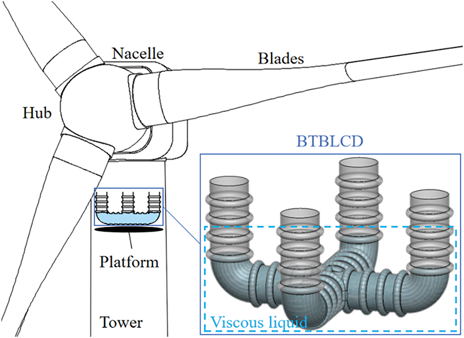
Figure 1: BTBLCD and installation position
The BTBLCD is an enhancement of the BTLCD, incorporating the bellow structure. Fig. 2 illustrates the sectional views of both the BTBLCD and BTLCD. The inclusion of the bellow structure enhances the frequency tuning flexibility and energy dissipation capability of the BTBLCD compared to the BTLCD, allowing it to adapt to various wind turbine tower structures and environmental conditions.
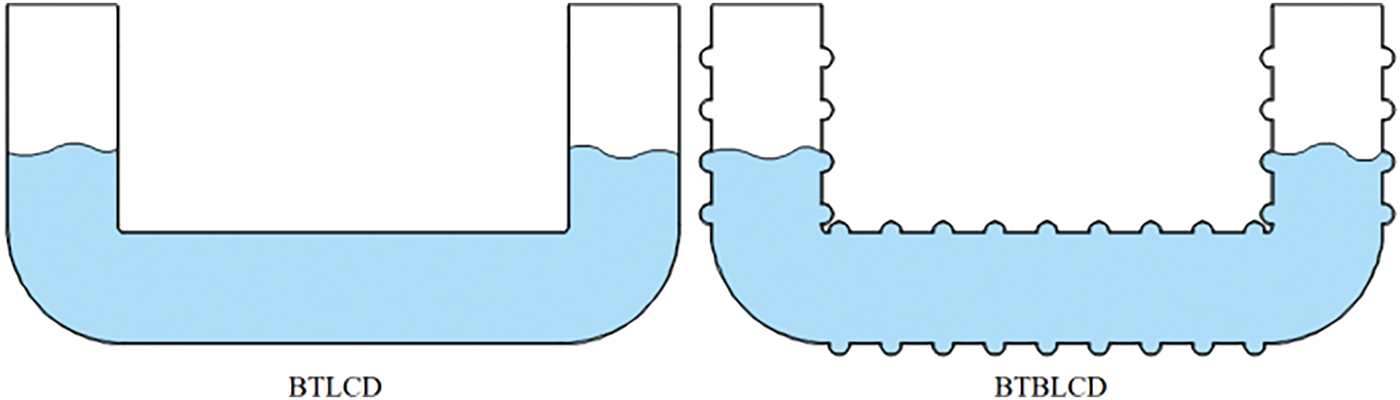
Figure 2: Section views of BTLCD and BTBLCD
The bidirectional vibration control structure of the BTBLCD features a maintenance access passage within the wind turbine tower, as shown in Fig. 3, with dimensions of 800 mm, meeting the specified requirements [28].
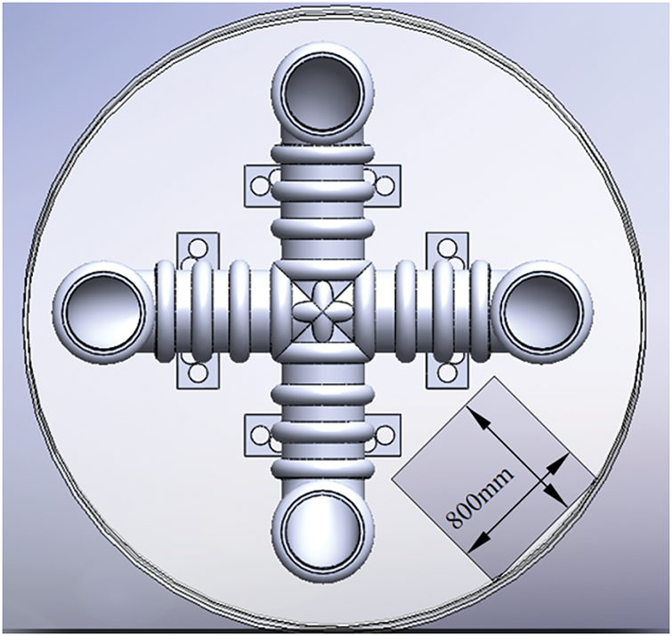
Figure 3: Maintenance channel of wind turbine
Initially, the maintenance access passage may have been designed at the center of the tower structure. However, as the BTBLCD is installed on a platform approximately 2 m below the top of the tower, maintenance personnel can access the BTBLCD or enter the wind turbine nacelle by utilizing detour ladders or other means.
2.2 Derivation of Damping Mechanism
The energy dissipation in the BTBLCD can be categorized into three primary components. The first component is the energy dissipation associated with the BTLCD. The second component arises from the increased contact area between the liquid and the tube, which is a result of the bellow structure of the BTBLCD, leading to higher viscous friction energy dissipation. The third component is the energy dissipation caused by turbulence in the liquid at the crests of the bellows within the BTBLCD.
The motion of the liquid within the BTBLCD is defined by
where
Assuming the fluid is incompressible and that the transverse velocity distribution of the liquid is constant, it follows that the fluid flow is turbulent. On the other hand, the dissipative forces associated with the BTBLCD are induced by the flow and can be categorized into three parts. The first and most significant part arises from the orifice or restriction located at the midpoint of the horizontal pipe. The second part is due to frictional resistance, while the third is the result of the abrupt change in flow direction at the corners of the device. These dissipative forces can be expressed as [24]:
where
The bellow structure of the BTBLCD enhances energy dissipation in the second component by expanding the contact area between the liquid and the pipe wall. Assuming that the liquid flow within the pipeline and is in a laminar state (as in when the fluid velocity is low), the frictional force between the pipe wall and the fluid can be described by the Darcy friction factor, with the pressure loss given by:
where
where
Energy dissipation in the third component of the BTBLCD primarily arises from the turbulence generated by the bellow structure during damper operation [30]. According to the generalized Kármán-Howarth equation, this occurs in the absence of assumptions of uniformity and isotropy [31]:
where
where
In summary, during the operation of the BTBLCD, in addition to the energy dissipation of the BTLCD, the bellow structure elongates the flow path of the liquid along the pipe wall, thereby inducing significant viscous friction and variations in flow velocity. Furthermore, turbulence may occur in the vicinity of the bellow regions, contributing to the increased energy dissipation in the second and third components of the BTBLCD. The energy dissipation of the BTBLCD can be expressed as follows:
During operation, the flow pattern of the viscous fluid within the damper is classified into turbulence and laminar flow. Fig. 4 provides a detailed diagram of the bellow structure. Turbulence occurs in the bellow section of the pipe, while laminar flow is observed in the middle sections.
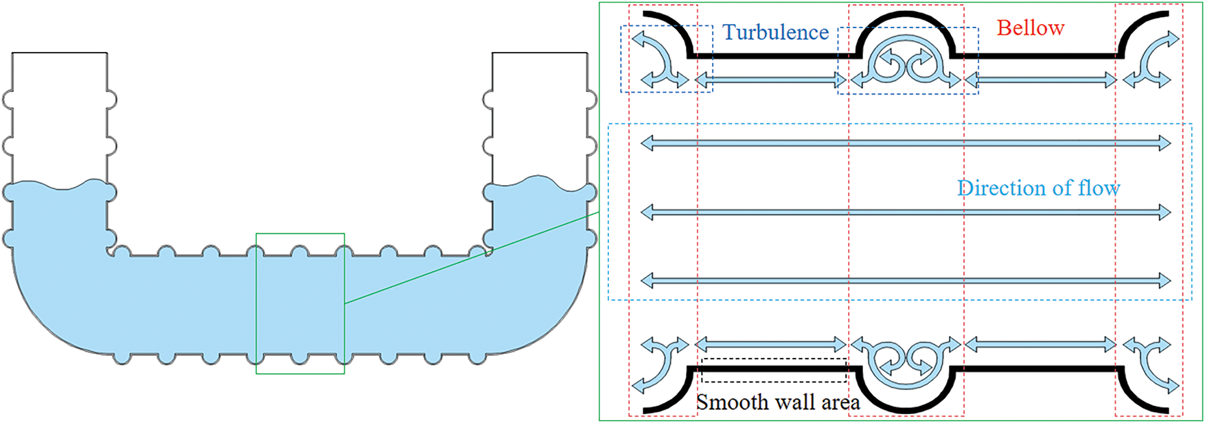
Figure 4: Detail of bellow construction
The natural frequency of the BTBLCD is mainly determined by the length of the liquid column. The natural frequency
where
The stiffness of the liquid column can be expressed as:
where
The mass of the liquid can be expressed as:
The natural frequency of the BTBLCD can be tuned by adjusting the height of the liquid column and its mass. By adjusting the length of the horizontal pipe
3 Dynamic Response of Seismic Excitations
3.1 Kinetics Model of the Wind Turbine with BTBLCD
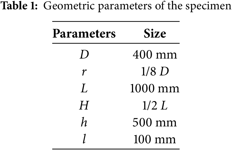
The model used in this study is based on a 2.0 MW wind turbine. As shown in Fig. 5, the tower height is 81.5 m, constructed from a conical hollow steel tube. The bottom diameter of the tower is 4.1 m with a wall thickness of 25 mm, tapering to a top diameter of 2.5 m and a wall thickness of 15 mm. The wall thickness of the tower decreases linearly with height. In the modeling process, the nacelle, hub, and blades were simplified as a concentrated mass of 60 t. The BTBLCD consists of vertical and transverse pipes, containing a viscous fluid. The primary design parameters include the internal pipe diameter
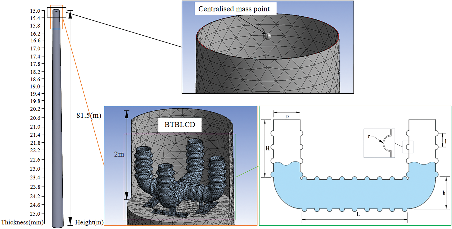
Figure 5: Finite element model diagram
3.2 Boundary Conditions Design
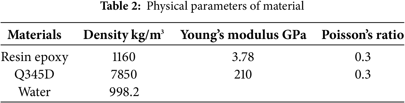
The U-shaped bellows are made of resin epoxy, with water as the viscous fluid and Q345D steel as the material of the tower, as detailed in Table 2.
The device is fixed on the platform 2 m below the top of the wind turbine tower structure in the dynamic response process. Furthermore, three different seismic excitations are applied to the base of the wind turbine tower structure, and the displacement at the base in the Y direction is constrained. Lateral and vertical loads are applied to the base of the wind turbine tower in the dynamic response test to evaluate the energy dissipation performance of the BTBLCD in both main and lateral seismic directions. Given the geometric symmetry of BTBLCD, its energy dissipation performance in both the main seismic direction and the lateral seismic direction can be considered as multi-directional energy dissipation. Additionally, in order to ensure consistency between the test scheme for dynamic response analysis and the subsequent shaking table test where loads are applied in a single direction, the dynamic response analysis in this study omits lateral loads and vertical stresses [34,35]. The BTBLCD and BTLCD are designed with 100% airflow permeability and 0% water permeability at the openings. This design ensures that the water within the liquid column remains contained during vibration, preventing any loss due to damper oscillation, thereby maintaining the stability of the liquid mass within the system. This stability not only prevents frequency drift but also ensures the reliability and consistency of performance comparisons between the BTBLCD and BTLCD.
This paper conducts dynamic response analysis of the uncontrolled wind turbine, as well as the BTBLCD-wind turbine and the BTLCD-wind turbine. Seismic excitations from EI Centro, Kobe, and Taft are applied to the base of the wind turbine tower. The multi-directional dynamic response analysis of the wind turbine is performed by adjusting the installation positions of the devices. As shown in Fig. 6, the vibration control directions of the BTBLCD are defined as the main seismic direction and the lateral seismic direction, based on the seismic loading direction along the X-axis of the coordinate system. The proposed device is capable of controlling bidirectional vibrations under seismic excitations along the X-axis. The bidirectional structure of the BTBLCD allows for optimal vibration control in both the seismic excitation direction and the perpendicular direction when aligned with the main seismic direction. Additionally, the device achieves optimal vibration control at an angle of 45 relative to the seismic excitation direction when aligned with the lateral seismic direction.
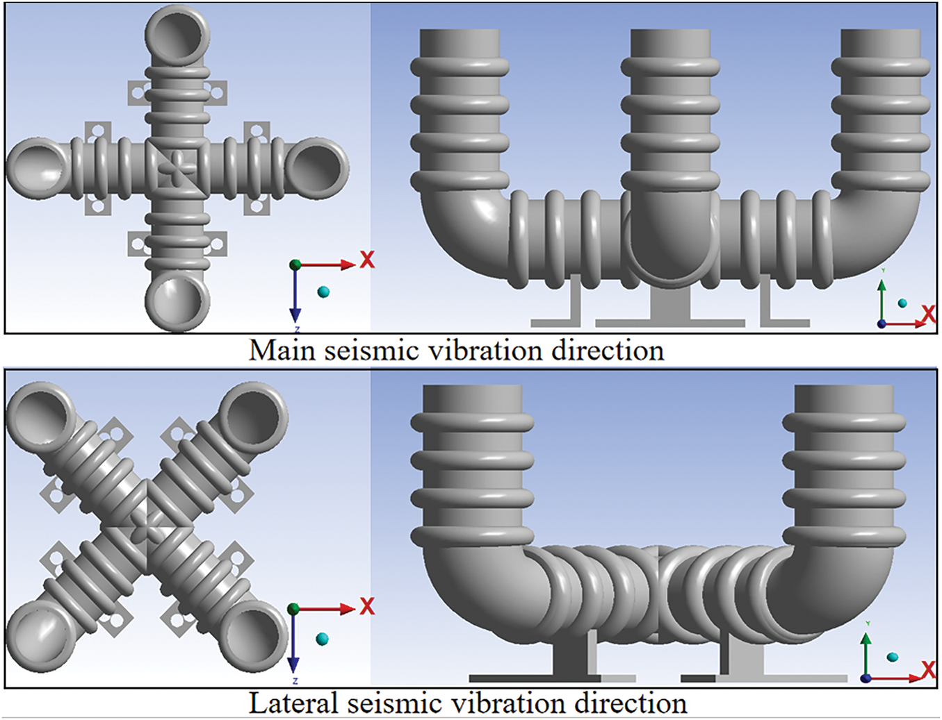
Figure 6: Model directions
4 Dynamic Response Results Analysis
4.1 Effects of Vibration Damping
Displacement and acceleration time histories were monitored at the top of the wind turbine tower structure. The peak vibration reduction rate and standard deviation vibration reduction rate of displacement and acceleration were used as criteria for evaluating energy dissipation performance. The corresponding formulas are presented below:
The standard deviation of displacement and acceleration is calculated using Eq. (14), where
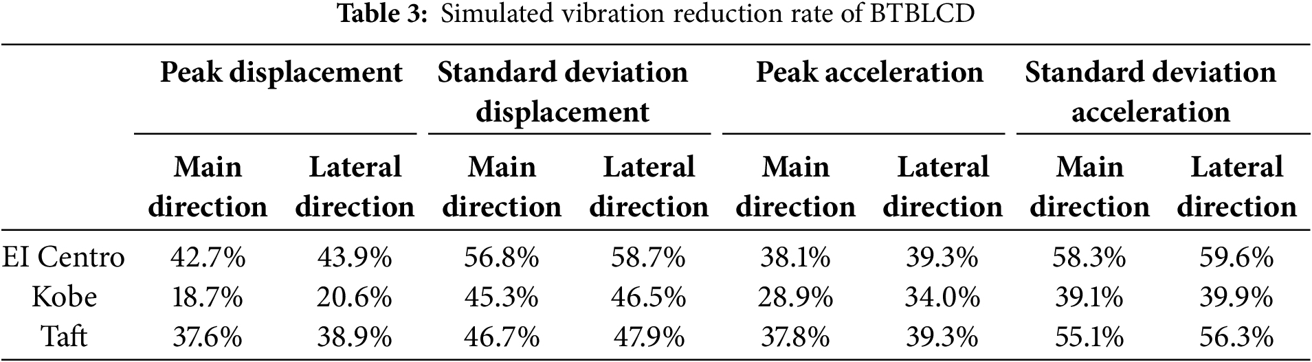
This paper does not focus on parametric studies but primarily investigates the effect of incorporating the bellow structure on energy dissipation performance. Fig. 7 illustrates the dynamic response graphs of peak displacement and standard deviation for wind turbines equipped with BTBLCD and BTLCD under seismic excitations from EI Centro, Kobe, and Taft. As shown in Fig. 7, the BTBLCD-wind turbine demonstrates superior energy dissipation performance in both directions under all three seismic excitations. According to Table 3, compared to the uncontrolled state, BTBLCD reduces the peak displacement of the structure by 18.7%–43.9%, the standard deviation of the displacement is reduced by 45.3%–58.7%, the peak acceleration is reduced by 28.9%–39.3%, and the standard deviation of the acceleration is reduced by 39.1%–59.6%.
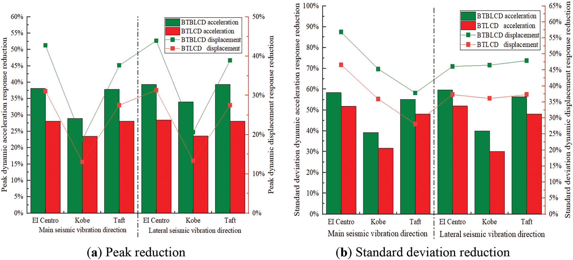
Figure 7: Simulated vibration reduction rate
The increase in the dynamic displacement and acceleration response reduction for the BTBLCD-wind turbine compared to the BTLCD-wind turbine in the lateral seismic direction is more significant than that in the main seismic direction. As shown in Table 3, this may be attributed to the lower number of bellows in the main seismic direction, which limits the full utilization of energy dissipation performance compared to the lateral seismic direction.
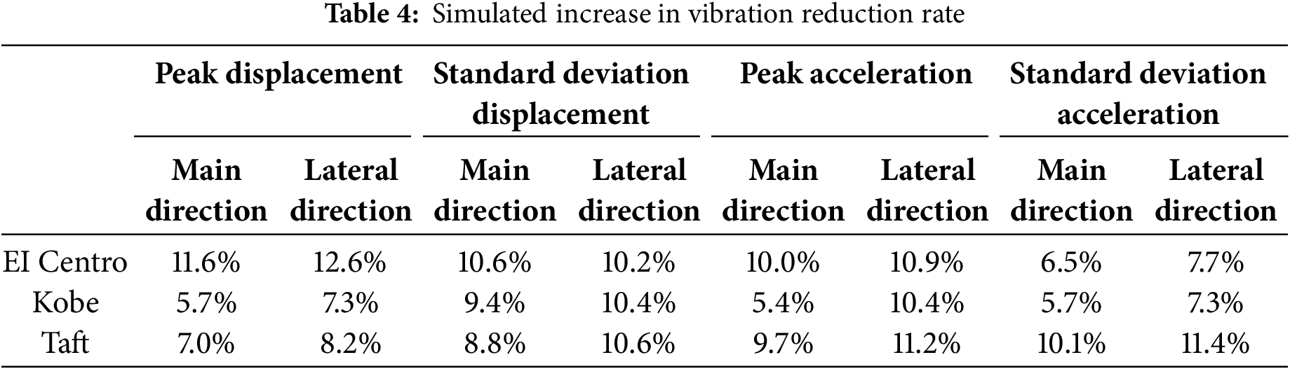
As described in Section 2, BTBLCD provides more energy dissipation mechanisms than BTLCD. Consequently, under all three seismic excitations, the damping effects of the BTBLCD-wind turbine are significantly superior to those of the BTLCD-wind turbine in both the main and lateral seismic directions. Compared to the BTLCD-wind turbine, the displacement vibration reduction rate of the BTBLCD-wind turbine increased by up to 12.6%, while the acceleration vibration reduction rate improved by up to 11.4%, as detailed in Table 4.
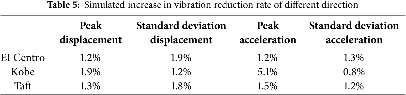
When the excitation is applied along the main seismic direction, the number of bellows along the liquid column flow path of the liquid column in the BTBLCD is reduced compared to the excitation condition in the lateral seismic direction excitation, resulting in leading to a decrease in damping efficiency and a relative weakening of the system’s system energy dissipation performance. Data from in Table 5 indicates indicate that under the lateral seismic excitation, the vibration reduction rate of the BTBLCD-wind turbine shows an increase in the displacement vibration reduction rate by 1.2%–1.9% and in the acceleration vibration reduction rate by 0.8%–5.1%, compared to the excitation of along the main seismic direction. This parameter difference visually clearly reflects the significant impact of different excitation directions direction on the damping effectiveness.
4.2 Analysis of Viscous Liquid
The sloshing of the viscous fluid inside the BTLCD and BTBLCD at the 20th second under the EI Centro in the main seismic direction is illustrated in Fig. 8. The arrows indicate the direction of fluid flow. From Fig. 8, it can be observed that there are significant differences in the sloshing patterns of the viscous fluid inside both systems at the 20th second. Specifically, the geometric features of the bellow structure in the BTBLCD have a significant effect on fluid behavior, especially near the bellow region, where the turbulence effects of the fluid are more pronounced compared to the non-bellow design of the BTLCD. This enhanced turbulence phenomenon complicates the movement pathways of the fluid during the sloshing process and significantly increases the dissipation of mechanical energy within the system.
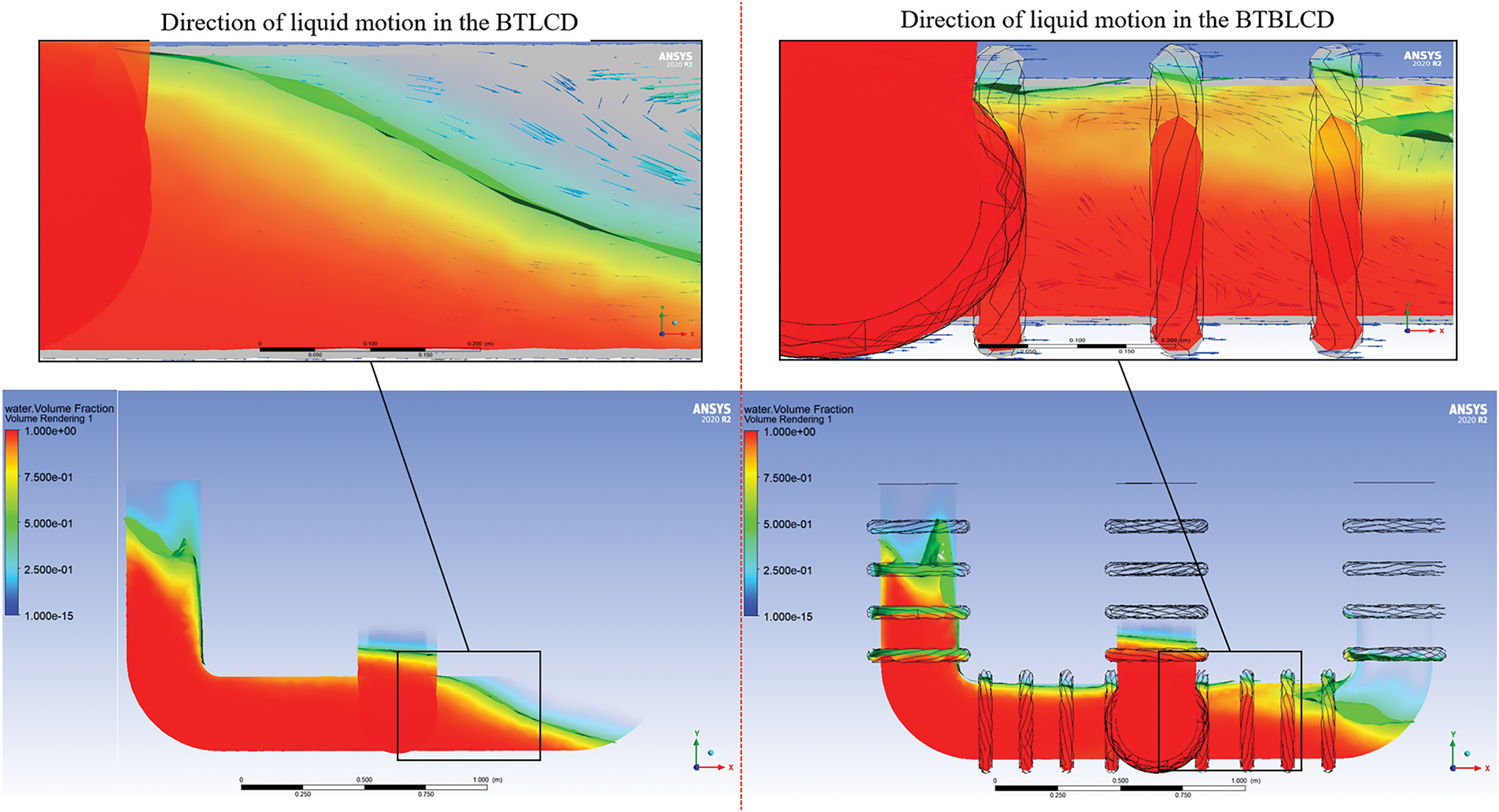
Figure 8: Vibration of viscous fluid at the 20th second under EI Centro
From the perspective of vibration control, this additional energy dissipation mechanism effectively enhances the system’s efficiency in absorbing and converting vibrational energy. The formation of complex fluid pathways and the intensification of turbulence facilitate the conversion of more mechanical energy into thermal energy or other forms of internal dissipation, thereby significantly improving the energy dissipation performance of the system. Consequently, the design of the BTBLCD not only optimizes the energy dissipation process but also demonstrates exceptional performance in suppressing structural vibrations, making it more suitable than the BTLCD for efficient damping applications in complex vibrational environments.
5 Test Vibration and Results Analysis
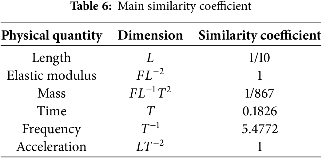
To accurately assess the energy dissipation performance of the BTBLCD, this study conducted a shaking table test. Fig. 9 shows the scaled model for the 81.5 m high wind turbine tower. The geometric similarity ratio of the wind turbine tower model is determined to be 1/10 (model/prototype), based on factors such as dimensions, load capacity, and the maximum allowable acceleration, velocity, and displacement of the shaking table. The top plate has a diameter of 250 mm, the bottom plate has a diameter of 280 mm, and the height is 600 mm. Since the test model uses the same physical parameters as the dynamic analysis model, including the same steel material, the similarity ratio for the elastic modulus is set to 1. Other similarity ratios are derived through dimensional analysis [36], and the primary ratios are provided in Table 6.
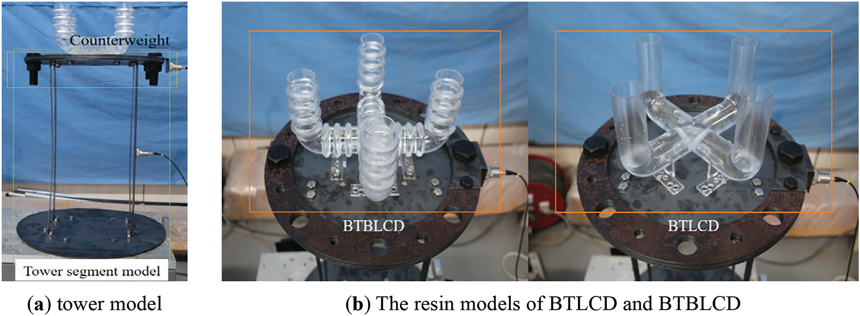
Figure 9: Test device
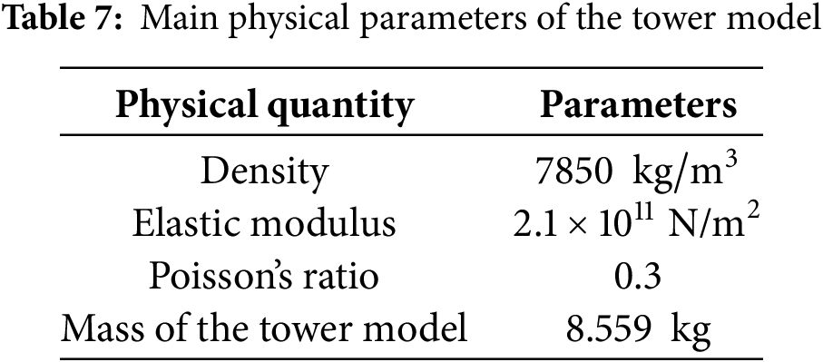
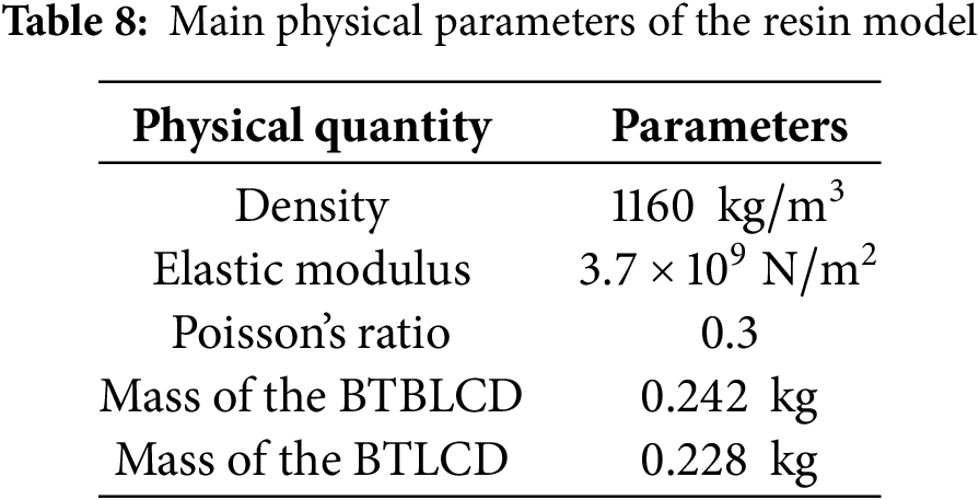
In the shaking table test, the mass of the BTBLCD was approximately 0.6 kg, with a mass ratio of 7.0%, requiring the addition of extra weight. At the start of the test, a 4.0 kg mass block was added to the top of the tower model, resulting in a mass ratio of 4.7%, which meets the required specifications. To achieve a 5% mass ratio between the device and the tower model, additional counterweights were added to the tower model [28]. To objectively and accurately compare the energy dissipation performance of BTBLCD and BTLCD, the liquid column heights for both devices were set to be identical. Furthermore, to prevent the test results from being affected by liquid mass loss due to device vibration, both BTBLCD and BTLCD maintained a liquid column height of 0.4 H throughout the test. After each excitation loading cycle, the liquid was emptied and refilled to 0.4 H to eliminate the effects of evaporation on liquid mass. Fig. 8 shows the physical diagrams of the BTBLCD, BTLCD, and the tower models. The top of the tower model is equipped with eight reserved bolt holes, as shown in Fig. 9b, which allow for switching the devices between the primary seismic direction and lateral seismic direction by altering their installation positions. The tower model is made of Q345D steel, and its main physical parameters are listed in Table 7. The BTBLCD and BTLCD models are fabricated using transparent resin materials through 3D printing, with the physical parameters of the resin models provided in Table 8.
A sweep frequency analysis was performed on the tower model, which revealed that the first-order frequency of the tower model was excited at a vibration frequency of 4.9 Hz, with the amplitude in the X-direction reaching its maximum. To investigate the energy dissipation performance of the BTBLCD under extreme conditions, sine waves within the frequency range of 4–5 Hz were generated using MATLAB and introduced as a third excitation, distinct from the EI Centro and Kobe.
In this test, excitation loads, including two seismic waves (EI Centro and Kobe) and sine waves, were applied in the X-direction at the base of the tower model. The loading intensity for each waveform was uniformly set to 1.5 g. Each set of excitations corresponded to three states: the uncontrolled tower model, the BTLCD-tower model, and the BTBLCD-tower model. After each loading, a waiting period was provided to allow the structure to return to stability before starting the next loading. Once the loading of a waveform set was completed, a white noise sweep frequency analysis was conducted, followed by the replacement of the devices for the next loading [37,38]. Specifically, the loading sequence for each group consisted of: the uncontrolled tower model, the BTLCD-tower model, and the BTBLCD-tower model. In total, six excitation groups were applied, three aligned with the primary seismic direction and three aligned with the lateral seismic direction.
This study investigates seismic control in the X-direction of the tower model. As depicted in Fig. 10, three monitoring points were established for this shaking table test, including both acceleration and displacement monitoring points [39]. These monitoring points were located at the top of the model. The test demonstrated the damping effect of the BTBLCD-tower model in both the primary and lateral seismic directions by modifying the installation positions of the BTBLCD and BTLCD. The WS-Z30-50 series small precision vibration table system used in this test consists of a shaking table, an electromagnetic vibrator, a data acquisition and control unit, a 500 W power amplifier, a charge amplifier, and control software. During the test, acceleration data were recorded using the INV9821 piezoelectric sensor, and data were collected with the INV3060 series network data collector at a sampling frequency of 100 Hz. Displacement data were monitored using the HG-C1100 micro laser displacement sensor, with data acquisition conducted by the DH5921 dynamic data acquisition instrument, also at a sampling frequency of 100 Hz.
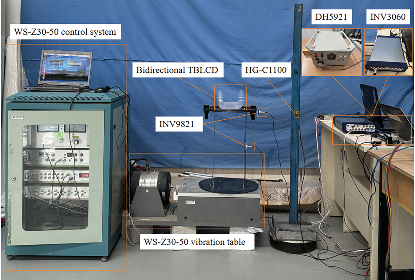
Figure 10: Test equipment
Comparing displacement time histories is a straightforward approach for evaluating vibration control. Since the peak displacement of the BTBLCD-tower model under the EI Centro exceeds that under Kobe, reaching 22.04 mm, the displacement time history under EI Centro was selected to investigate the relationship between the energy dissipation performance of the BTBLCD and the vibration amplitude of the tower model. The displacement time history curve in the primary seismic direction under EI Centro is shown in Fig. 11. It is evident that as the vibration amplitude increases, the damping effect of the BTBLCD becomes more pronounced. This result demonstrates the effectiveness of the BTBLCD in providing damping, especially under larger vibration amplitudes, thus emphasizing its energy dissipation capacity.
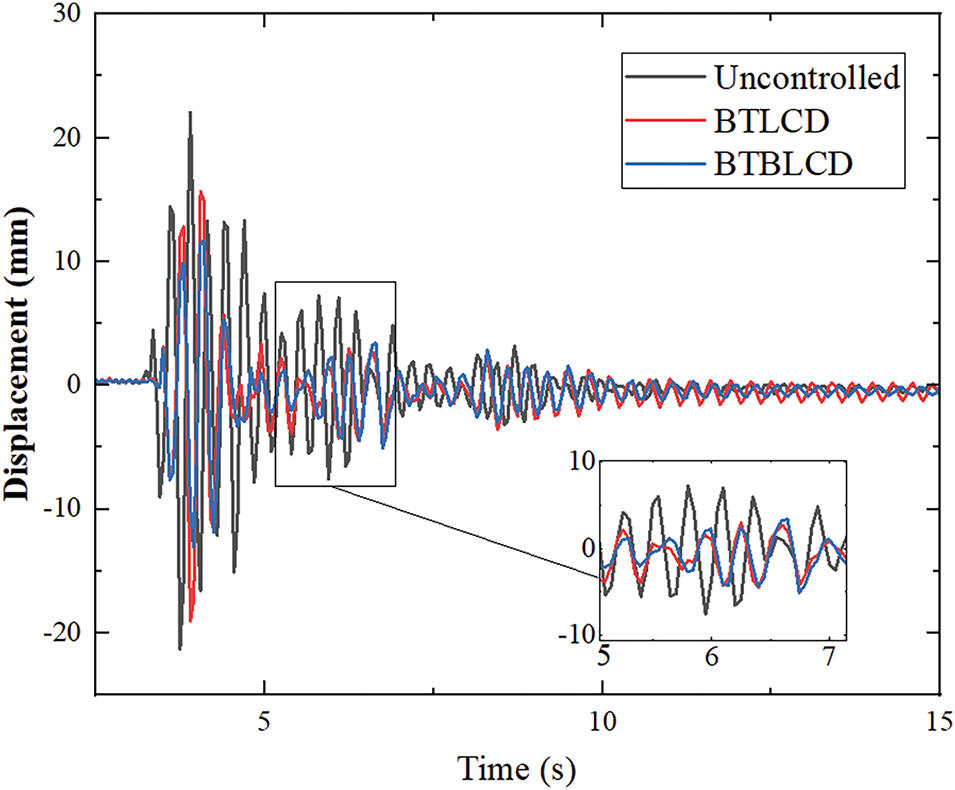
Figure 11: Displacement time history
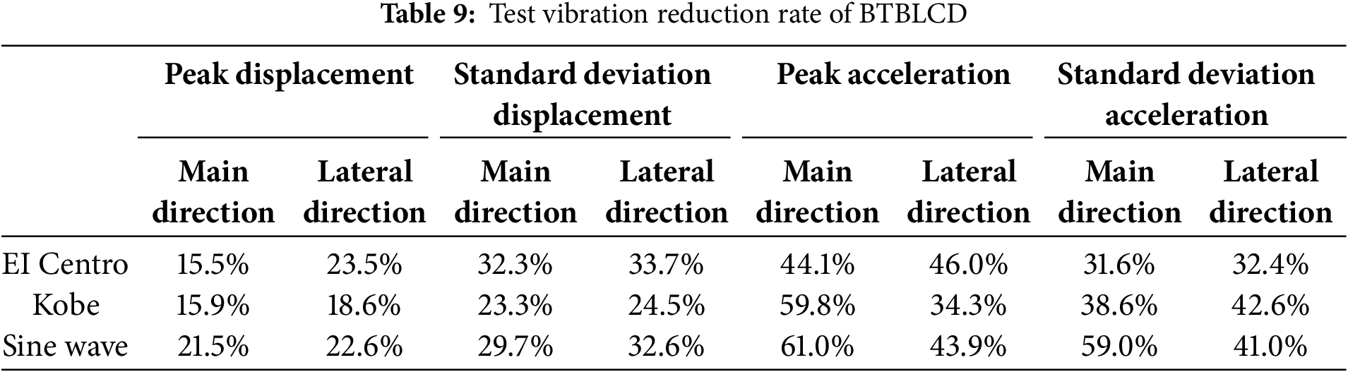
The test data indicate that the BTBLCD-tower model demonstrates superior energy dissipation performance, as shown in Fig. 12. The energy dissipation performance data are summarized in Table 9. Compared to the uncontrolled state, the BTBLCD reduces peak displacement by 15.5%–22.6%, standard deviation of displacement by 23.3%–33.7%, peak acceleration by 34.3%–61.0%, and standard deviation of acceleration by 31.6%–59.0%. Data analysis reveals that the energy dissipation performance of the BTBLCD is more effectively demonstrated under large-amplitude sine wave excitation. Specifically, the dynamic displacement and acceleration responses of the BTBLCD-tower model are reduced more significantly under sine wave excitation than under EI Centro and Kobe. The vibration reduction rates for displacement and acceleration in the BTBLCD-tower model also outperform those in the BTLCD-tower model. As shown in Table 9, under three different excitations, the increase in vibration reduction rate for the lateral seismic direction of the BTBLCD-tower model is generally superior to that in the main seismic direction. The specific increases in the vibration reduction rate of the BTBLCD-tower model are presented in Table 10.
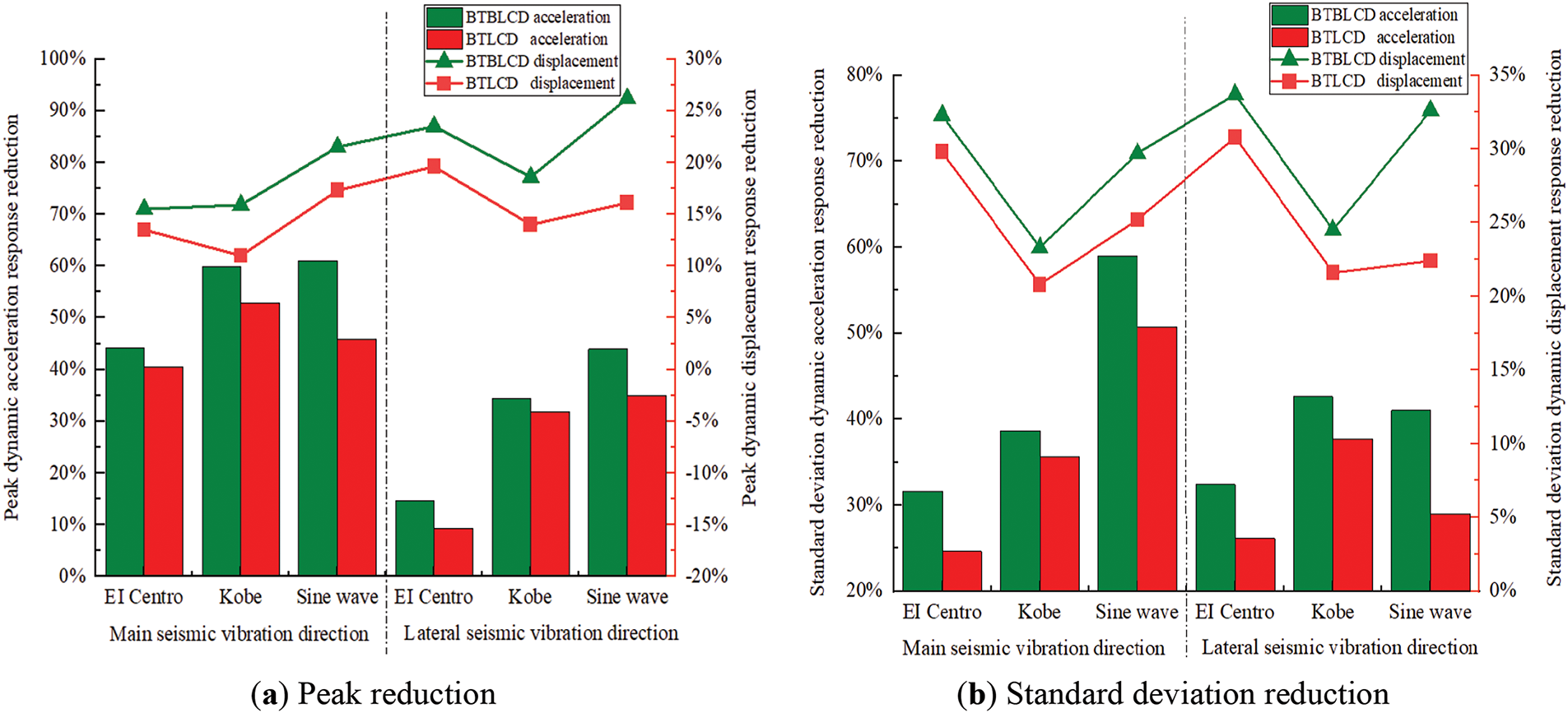
Figure 12: Test vibration reduction rate

The test results confirm that the BTBLCD provides more significant damping effects than the BTLCD under various seismic excitations. This difference is primarily attributed to the larger pipe wall friction coefficient of the BTBLCD and the turbulence effects generated by the bellow structure design, which enhance the longitudinal damping force. These design features enable the BTBLCD to more effectively absorb and dissipate structural vibration energy, leading to superior energy dissipation performance.
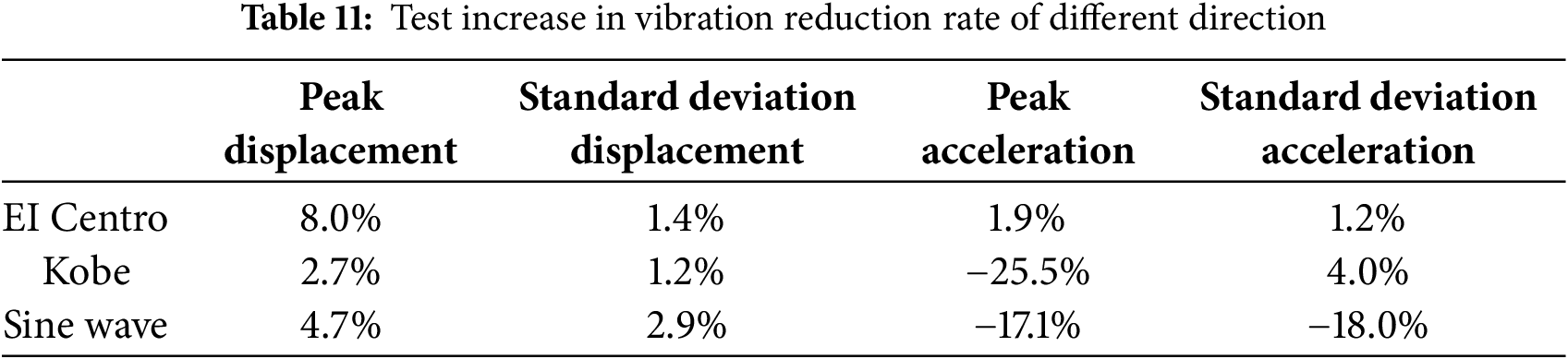
In the shaking table test, when the excitation direction is along the main seismic direction, the number of bellows along the liquid column flow path is fewer than when the excitation direction is along the lateral seismic direction, resulting in relatively weaker energy dissipation performance. As shown in Table 11, the vibration reduction rate of the BTBLCD-tower model under lateral seismic excitation is superior to that under main seismic excitation. The energy dissipation characteristics of the BTBLCD observed in dynamic response analysis differ from those obtained from the shake table test. This discrepancy is primarily due to the significantly larger vibration amplitudes encountered in wind turbine dynamic analyses compared to the scaled tower model tested on the shake table.
Displacement time histories serve as critical diagnostic tools for amplitude evaluation, as demonstrated in Fig. 13. Under the same excitation intensity of EI Centro, the BTBLCD wind turbine exhibited a maximum displacement of 500 mm at the tower top in dynamic response analysis, whereas the BTBLCD tower model demonstrated a peak displacement of 23 mm at its apex during the shake table test. Given the amplitude-dependent nature of the BTBLCD energy dissipation characteristics, the device demonstrates superior energy dissipation performance in large-amplitude dynamic analyses compared to small-amplitude shaking table tests.
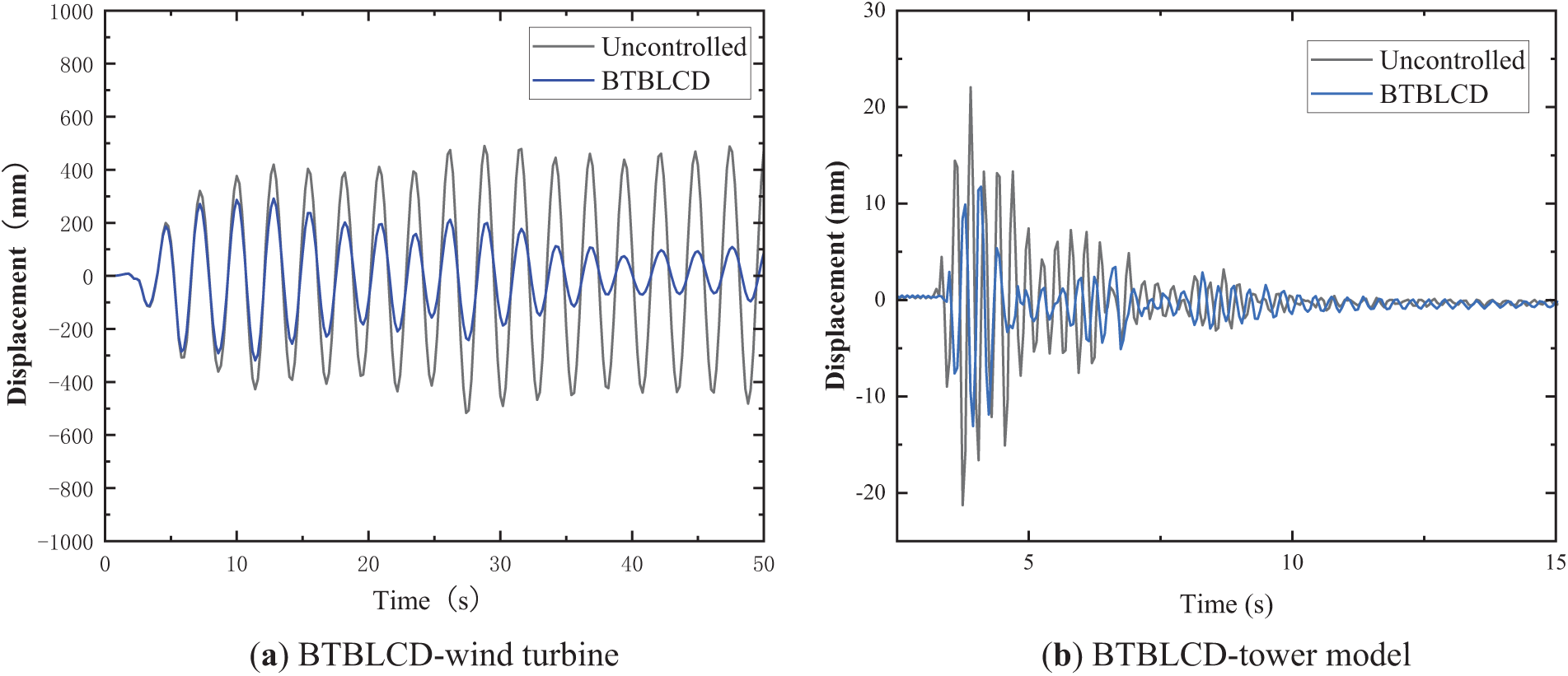
Figure 13: Time history under EI Centro
The time histories under sine wave excitation for the BTBLCD-tower model, BTLCD-tower model, and uncontrolled tower model are shown in Fig. 14. Fig. 14a,b demonstrates that the BTBLCD-tower model exhibits superior displacement energy dissipation performance compared to the BTLCD-tower model under sine wave excitation. Particularly, during the time interval from 5 to 7.5 s, when the vibration amplitude is larger, the bellow structure in the BTBLCD induces more significant turbulent phenomena due to the higher liquid flow velocity, thereby enhancing the damping effectiveness [31]. The BTBLCD-tower model also shows a more pronounced damping effect than the BTLCD-tower model during phases with smaller vibration amplitudes. As shown in Fig. 12c,d, the acceleration energy dissipation performance of the BTBLCD-tower model under sine wave excitation in the lateral seismic direction is superior to that in the main seismic direction. Additional structural elements are involved in the damper’s operation to increase the number of turbulence events, thereby enhancing energy dissipation performance. Specifically, an increase in
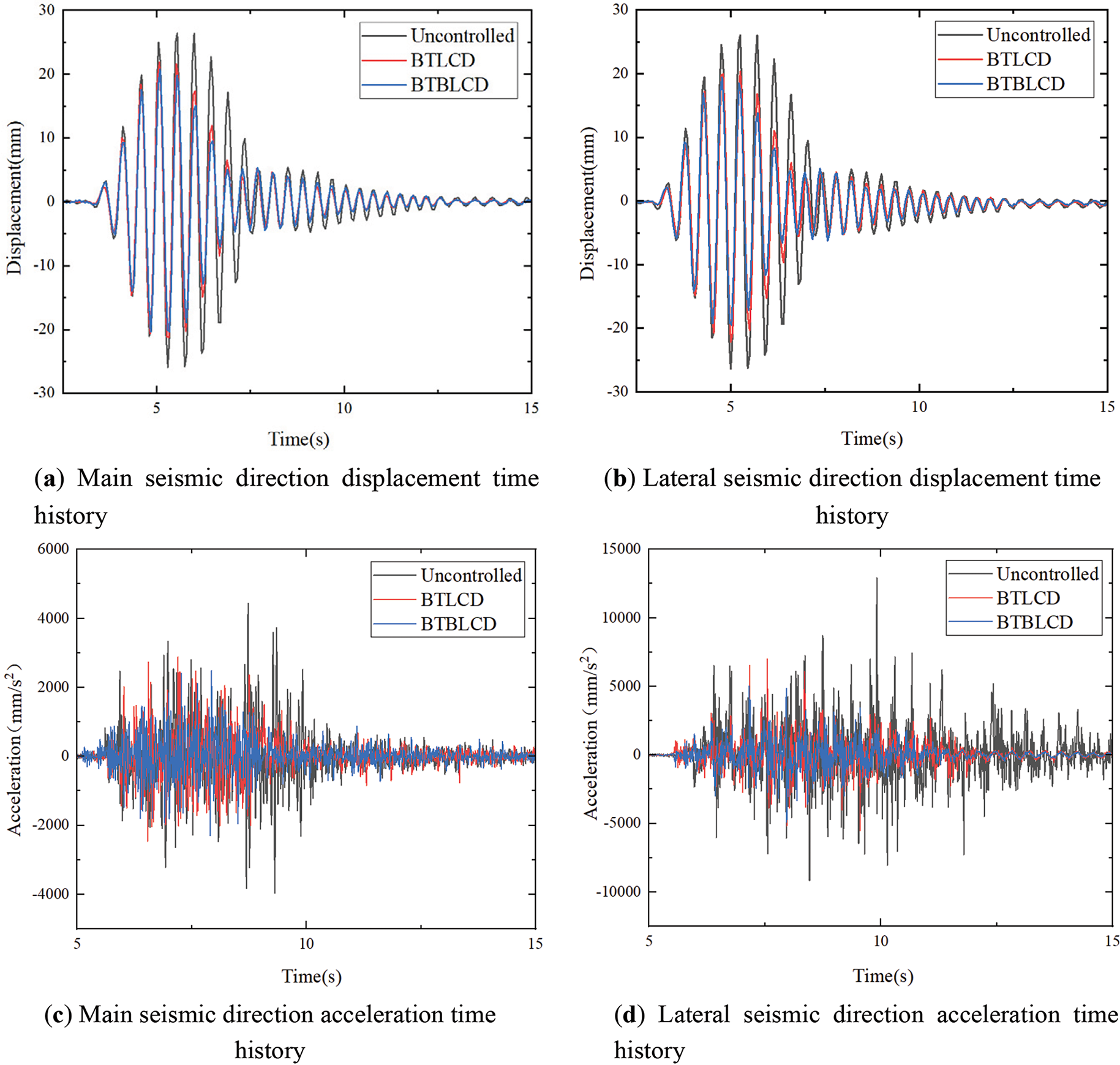
Figure 14: Test time history curve under sine wave
The test results confirmed that the BTBLCD demonstrated reliable and stable energy dissipation performance under three different excitations and both in the direction of the main seismic and in the lateral seismic direction. Firstly, compared to the single energy dissipation mode of BTLCD [24], the BTBLCD exhibited superior energy dissipation performance due to the bellow structure, it can increase energy dissipation in the second and third components of the device during operation. Secondly, under larger amplitude excitation, BTBLCD fully demonstrates its damping superiority as the increased excitation amplitude induces greater liquid flow velocity within the device, which generates enhanced turbulent effects and consequently leads to amplified energy dissipation [31]. Finally, the BTBLCD exhibited better energy dissipation performance in the lateral seismic direction than in the main seismic direction, primarily due to the greater turbulent effects generated in the lateral direction, which increase the energy dissipation in the second and third components.
The reduction in dynamic response observed in the tests was less pronounced than that predicted by the dynamic response analysis in Section 3. As demonstrated in the work by Yalla et al. [33] on nonlinear liquid dampers, the quadratic relationship between flow velocity and energy dissipation provides a theoretical foundation for the turbulence-induced energy dissipation observed in BTBLCD systems. This discrepancy can be attributed to the vibration amplitude of the BTBLCD. Under the same excitation, the amplitude at the top of the wind turbine tower structure is significantly larger than that at the top of the tower model. Therefore, the bellow structure of the BTBLCD can generate more intense turbulent effects at larger amplitudes, leading to better energy dissipation performance.
This study aims at seismic vibration control of slender and flexible wind turbine tower structures, proposing a novel passive control device, the BTBLCD. Initially, the paper introduces the detailed design and energy dissipation mechanism of the BTBLCD. The energy dissipation performance of the BTBLCD is further analyzed through two-way fluid-structure coupling numerical simulations. Finally, the numerical simulation results are validated through shaking table tests. Dynamic response analysis and shaking table tests demonstrate that the device achieves maximum reductions of approximately 59.6% in dynamic acceleration responses and 58.7% in dynamic displacement responses. However, directional differences emerge as a significant characteristic, with comparative results revealing enhanced vibration reduction rates in the lateral seismic direction, specifically showing 8.0% greater displacement reduction and 5.1% higher acceleration mitigation compared to the primary seismic direction. Moreover, under sine wave excitation, the device demonstrates a performance improvement of 6.1% in dynamic displacement control and 27.4% in acceleration, indicating a positive correlation between vibration intensity and energy dissipation efficiency. This comprehensive experimental validation confirms the adaptive dissipation mechanism of the BTBLCD while highlighting its orientation-sensitive and amplitude-modulated operational features.
Additionally, while the BTBLCD demonstrates notable energy dissipation capabilities, there are critical limitations that require further investigation, particularly in parameter optimization and performance validation under extreme operational conditions. Current implementations show sensitivity to geometric parameters such as bellow radius and bellow spacing, where suboptimal configurations may compromise turbulence generation and nonlinear damping effects. Furthermore, while laboratory-scale testing under simulated seismic loads shows promise, there is a lack of full-scale validation under combined wind-wave-earthquake loading. Nevertheless, the device shows significant potential for application in next-generation super-tall wind turbines. Its inherent maintenance-free operation and corrosion resistance further enhance its suitability for offshore environments. Future research should focus on establishing a parametric optimization framework combining computational fluid dynamics and topology optimization to systematically analyze the interdependencies between bellow geometry, liquid viscosity, and dissipation efficiency across operational spectra. Concurrently, hybrid system development must address control algorithm synchronization challenges between the passive damping of the BTBLCD and active mass dampers. These advancements could position the BTBLCD as a transformative solution for gigawatt-class offshore wind energy systems, addressing current technological gaps in adaptive vibration control.
Acknowledgement: The authors appreciate the assistance of the Lanzhou University of Technology Structural Engineering Laboratory in conducting the test.
Funding Statement: The authors disclosed receipt of the following financial support for the research, authorship, and/or publication of this paper: This study is supported by the National Science Foundation of China (Grant No. 52368074), the Science Fund for Distinguished Young Scholars of Gansu Province (No. 21JR7RA267), and Hongliu Outstanding Young Talents Program of Lanzhou University of Technology.
Author Contributions: The authors confirm contribution to the paper as follows: study conception and design: Wanrun Li, Xiwei Wang; data collection: Xiwei Wang, Yining Wang; analysis and interpretation of results: Xiwei Wang, Wanrun Li, Wenhai Zhao, Yongfeng Du; draft manuscript preparation: Xiwei Wang, Wanrun Li, Yongfeng Du. All authors reviewed the results and approved the final version of the manuscript.
Availability of Data and Materials: The data used to support the findings of the study are available from the corresponding author upon request.
Ethics Approval: This study focused on the design and testing of a novel damper. All experiments were conducted in a controlled laboratory environment using non-biological materials. No human or animal subjects were involved in this research. Formal ethics approval was not required for this type of engineering analysis.
Conflicts of Interest: The authors declare no conflicts of interest to report regarding the present study.
References
1. Council GWE. GWEC global wind report. Bonn, Germany: Global Wind Energy Council; 2023. 120 p. Report No.: 1. [Google Scholar]
2. Risi RD, Bhattacharya S, Goda K. Seismic performance assessment of monopile-supported offshore wind turbines using unscaled natural earthquake records. Soil Dyn Earthq Eng. 2018;109(6):154–72. doi:10.1016/j.soildyn.2018.03.015. [Google Scholar] [CrossRef]
3. Patil A, Jung S, Kwon OS. Structural performance of a parked wind turbine tower subjected to strong ground motions. Eng Struct. 2016;120(8):92–102. doi:10.1016/j.engstruct.2016.04.020. [Google Scholar] [CrossRef]
4. Caterino N. Semi-active control of a wind turbine via magnetorheological dampers. J Sound Vib. 2015;345(8):1–17. doi:10.1016/j.jsv.2015.01.022. [Google Scholar] [CrossRef]
5. Liu G, Lei Z, Wang H. Investigation and optimization of a pre−stressed tuned mass damper for wind turbine tower. Structural Control Hlth. 2022;29(3):e2894. doi:10.1002/stc.2894. [Google Scholar] [CrossRef]
6. Zhang Z, Basu B, Nielsen SR. Real−time hybrid aeroelastic simulation of wind turbines with various types of full−scale tuned liquid dampers. Wind Energy. 2019;22(2):239–56. doi:10.1002/we.2281. [Google Scholar] [CrossRef]
7. Khodaie N. Parametric study of wind-induced vibration control of tall buildings using TMD and TLCD systems. Structures. 2023;57(7):105126. doi:10.1016/j.istruc.2023.105126. [Google Scholar] [CrossRef]
8. Ding H, Bi K, Song J, Fang X. Vertical vibration control of structures with tuned liquid column dampers. Int J Mech Sci. 2024;279(7–8):109502. doi:10.1016/j.ijmecsci.2024.109502. [Google Scholar] [CrossRef]
9. Si Y, Karimi HR, Gao H. Modeling and parameter analysis of the OC3−hywind floating wind turbine with a tuned mass damper in nacelle. J Appl Math. 2013;2013(1):679071. doi:10.1155/2013/679071. [Google Scholar] [CrossRef]
10. Wang W, Li X, Pan Z, Zhao Z. Motion control of pentapod offshore wind turbines under earthquakes by tuned mass damper. J Mar Sci Eng. 2019;7(7):224. doi:10.3390/jmse7070224. [Google Scholar] [CrossRef]
11. Chen JL, Georgakis CT. Spherical tuned liquid damper for vibration control in wind turbines. J Vib Control. 2015;21(10):1875–85. doi:10.1177/1077546313495911. [Google Scholar] [CrossRef]
12. Ghaemmaghami A, Kianoush R, Yuan XX. Numerical modeling of dynamic behavior of annular tuned liquid dampers for applications in wind towers. Comput-Aided Civ Inf. 2013;28(1):38–51. doi:10.1111/j.1467-8667.2012.00772.x. [Google Scholar] [CrossRef]
13. Zhang Z, Staino A, Basu B, Nielsen SR. Performance evaluation of full-scale tuned liquid dampers (TLDs) for vibration control of large wind turbines using real-time hybrid testingure. Eng Struct. 2016;126(6):417–31. doi:10.1016/j.engstruct.2016.07.008. [Google Scholar] [CrossRef]
14. Ha M, Cheong C. Pitch motion mitigation of spar-type floating substructure for offshore wind turbine using multilayer tuned liquid damper. Ocean Eng. 2016;116(2):157–64. doi:10.1016/j.oceaneng.2016.02.036. [Google Scholar] [CrossRef]
15. Buckley T, Watson P, Cahill P, Jaksic V, Pakrashi V. Mitigating the structural vibrations of wind turbines using tuned liquid column damper considering soil-structure interaction. Renew Energy. 2018;120(8):322–41. doi:10.1016/j.renene.2017.12.090. [Google Scholar] [CrossRef]
16. Ding H, Wang W, Liu JF, Wang JT, Le ZJ, Zhang J, et al. On the size effects of toroidal tuned liquid column dampers for mitigating wind-and wave-induced vibrations of monopile wind turbines. Ocean Eng. 2023;273(12):113988. doi:10.1016/j.oceaneng.2023.113988. [Google Scholar] [CrossRef]
17. Lu Y, Xie W, He Y, Liang H, Zhang Z, Chen X, et al. Shaking table test of TLD/TLCD vibration control for offshore wind turbine support structure. Appl Ocean Res. 2024;153(7):104207. doi:10.1016/j.apor.2024.104207. [Google Scholar] [CrossRef]
18. Colwell S, Basu B. Tuned liquid column dampers in offshore wind turbines for structural control. Eng Struct. 2009;31(2):358–68. doi:10.1016/j.engstruct.2008.09.001. [Google Scholar] [CrossRef]
19. Mensah AF, Dueñas-Osorio L. Improved reliability of wind turbine towers with tuned liquid column dampers (TLCDs). Struct Saf. 2014;47:78–86. doi:10.1016/j.strusafe.2013.08.004. [Google Scholar] [CrossRef]
20. Hemmati A, Oterkus E, Barltrop N. Fragility damping of offshore wind turbines using tuned liquid column dampers. Soil Dyn Earthq Eng. 2019;125(6):105705. doi:10.1016/j.soildyn.2019.105705. [Google Scholar] [CrossRef]
21. Liu Y, Li X, Shi W, Wang W, Jiang Z. Vibration control of a monopile offshore wind turbines under recorded seismic waves. Renew Energy. 2024;226(1):120455. doi:10.1016/j.renene.2024.120455. [Google Scholar] [CrossRef]
22. James M, Haldar S. Seismic vulnerability of jacket supported large offshore wind turbine considering multidirectional ground motions. Structures. 2022;43(13):407–23. doi:10.1016/j.istruc.2022.06.049. [Google Scholar] [CrossRef]
23. Navdar MB, Çelebi E, Dal H, Yilmaz FC, Engin T. Experimental and numerical study on vibration mitigation of slender structures with TLCD under second-order effects. J Build Eng. 2025;102:111675. doi:10.1016/j.jobe.2024.111675. [Google Scholar] [CrossRef]
24. Rozas L, Boroschek RL, Tamburrino A, Rojas M. A bidirectional tuned liquid column damper for reducing the seismic response of buildings. Struct Control Hlth. 2016;23(4):621–40. doi:10.1002/stc.1784. [Google Scholar] [CrossRef]
25. Xie F, Aly AM. Structural control and vibration issues in wind turbines: a review. Eng Struct. 2020;210(15):110087. doi:10.1016/j.engstruct.2019.110087. [Google Scholar] [CrossRef]
26. Machado MR, Dutkiewicz M. Wind turbine vibration management: an integrated analysis of existing solutions, products, and Open-source developments. Energy Rep. 2024;11:3756–91. doi:10.1016/j.egyr.2024.03.014. [Google Scholar] [CrossRef]
27. Truong HVA, Dang TD, Vo CP, Ahn KK. Active control strategies for system enhancement and load mitigation of floating offshore wind turbines: a review. Renew Sust Energ Rev. 2022;170(6):112958. doi:10.1016/j.rser.2022.112958. [Google Scholar] [CrossRef]
28. IEC. 61400-1: Wind turbines part 1: design requirements. Geneva, Swizterland: International Electrotechnical Commission; 2005. 164 p. Report No.: 1. [Google Scholar]
29. Park S, Glade M, Lackner MA. Multi-objective optimization of orthogonal TLCDs for reducing fatigue and extreme loads of a floating offshore wind turbine. Eng Struct. 2020;209(1):110260. doi:10.1016/j.engstruct.2020.110260. [Google Scholar] [CrossRef]
30. Portela FA, Papadakis G, Vassilicos JC. The turbulence cascade in the near wake of a square prism. J Fluid Mech. 2017;825:315–52. doi:10.1017/jfm.2017.390. [Google Scholar] [CrossRef]
31. Apostolidis A, Laval JP, Vassilicos JC. Turbulent cascade in fully developed turbulent channel flow. J Fluid Mech. 2023;967:A22. doi:10.1017/jfm.2023.487. [Google Scholar] [CrossRef]
32. Shah MU, Usman M. An experimental study of tuned liquid column damper controlled multi-degree of freedom structure subject to harmonic and seismic excitations. PLoS One. 2022;17(6):e0269910. doi:10.1371/journal.pone.0269910. [Google Scholar] [PubMed] [CrossRef]
33. Yalla SK, Kareem A, Kantor JC. Semi-active tuned liquid column dampers for vibration control of structures. Eng Struct. 2001;23(11):1469–79. doi:10.1016/S0141-0296(01)00047-5. [Google Scholar] [CrossRef]
34. Kalfas KN, Amirabad NG, Forcellini D. The role of shear modulus on the mechanical behavior of elastomeric bearings when subjected to combined axial and shear loads. Eng Struct. 2021;248(6):113248. doi:10.1016/j.engstruct.2021.113248. [Google Scholar] [CrossRef]
35. Rastgoo Moghadam S, Konstantinidis D. Experimental and analytical studies on the horizontal behavior of elastomeric bearings under support rotation. J Struct Eng. 2021;147(4):04021024. doi:10.1061/(ASCE)ST.1943-541X.0002962. [Google Scholar] [CrossRef]
36. Al-Hababi T, Alkayem NF, Cui L, Zhang S, Liu C, Cao M. The coupled effect of temperature changes and damage depth on natural frequencies in beam-like structures. Struct Control Hlth. 2022;16(1):15–35. doi:10.32604/sdhm.2022.020418. [Google Scholar] [CrossRef]
37. Zhao J, Wang Y, Ma Z. Response spectrum analysis of 7-story assembled frame structure with energy dissipation system. Struct Control Hlth. 2023;17(2):159. doi:10.32604/sdhm.2023.09601. [Google Scholar] [CrossRef]
38. Tahamouli Roudsari M, Cheraghi K, Aghayari R. Investigating the retrofit of RC frames using TADAS yielding dampers. Struct Control Hlth. 2022;16(4):343. [Google Scholar]
39. Lu Z, Zhao S, Ma C, Dai K. Experimental and analytical study on the performance of wind turbine tower attached with particle tuned mass damper. Eng Struct. 2023;294(2):116784. doi:10.1016/j.engstruct.2023.116784. [Google Scholar] [CrossRef]
Cite This Article
 Copyright © 2025 The Author(s). Published by Tech Science Press.
This work is licensed under a Creative Commons Attribution 4.0 International License , which permits unrestricted use, distribution, and reproduction in any medium, provided the original work is properly cited.
 Downloads
 Citation Tools