
 Submit a Paper
 Propose a Special lssue
 Open Access
ARTICLE

Vision-Based Crack Detection for Wall-Climbing Robot on Building Surface
1 State Key Laboratory of Precision Blasting, Jianghan University, Wuhan, 430056, China
2 School of Intelligent Manufacturing, Jianghan University, Wuhan, 430056, China
3 Dongfeng Special Component Co., Ltd., Shiyan, 442000, China
* Corresponding Author: Fancong Zeng. Email:
(This article belongs to the Special Issue: Non-contact Sensing in Infrastructure Health Monitoring)
Structural Durability & Health Monitoring 2026, 20(2), 20 https://doi.org/10.32604/sdhm.2025.073124
Received 11 September 2025; Accepted 10 November 2025; Issue published 31 March 2026
 View Full Text
 Download PDF
Abstract
The present study proposes an autonomous visual inspection system based on Wall-Climbing Robot (WCR), with a view to addressing the shortcomings of traditional building crack detection methods, namely their low measurement accuracy, high manual dependence and insufficient environmental adaptability. The system has been developed to construct a crack recognition model with robust illumination adaptation by fusing the improved YOLOv5s target detection algorithm with the Canny edge enhancement algorithm. The system has been realized as a lightweight deployment on an embedded device (MaixCAM). The robot platform employs a design scheme integrating a dual-chamber negative pressure adsorption mechanism and a differential drive system, which effectively addresses the key technical challenges of stable motion and real-time image acquisition on the vertical wall. Concurrently, the embedded vision processing module accomplishes efficient data parsing within dynamic environments. The experimental findings demonstrate that the system’s detection accuracy consistently maintains a range of 88.3% to 95.6% under conditions of 1000-50 lux illumination. In comparison with conventional detection methods, the recognition accuracy of various types of building cracks is enhanced by 17.3%. This study proposes a pioneering technical solution for the intelligent detection of complex building surface defects, which holds significant engineering application value.Keywords
The rapid acceleration of global urbanization has led to a marked increase in the prevalence of high-rise and super high-rise structures, which serve as emblematic features of modern urban development. However, these edifices are susceptible to progressive degradation due to multi-factorial stressors, including environmental exposure, material fatigue, and anthropogenic activities, manifesting as structural defects such as crack propagation, corrosion, and deformation [1,2]. Left unmitigated, such deterioration can precipitate catastrophic structural failures, posing significant risks to public safety and infrastructure integrity. Consequently, the development of robust and precise structural health monitoring systems is critical to safeguarding urban infrastructure.
To enhance industrial automation and productivity, governments worldwide have enacted strategic policies to accelerate the adoption of intelligent manufacturing and robotic technologies. These include China’s “14th Five-Year Plan” for the Development of National Strategic Emerging Industries, Germany’s “High-Tech Strategy 2025”, India’s “National Robotics Strategy”, and Japan’s “New Robotics Strategy”. The United States has also introduced the “National Robotics Initiative 3.0”.
Despite the pervasive integration of robotics across industries, high-risk operations, particularly in industrial settings, continue to rely on manual labor, exposing workers to significant occupational hazards. The deployment of robotic systems for tasks such as structural inspections and maintenance in elevated or hazardous environments represents an inevitable paradigm shift in industrial practice. This transition not only mitigates the incidence of workplace accidents but also enhances operational efficiency and diagnostic precision, offering a transformative approach to intelligent infrastructure maintenance.
Wall-climbing robots (WCRs) have emerged as a specialized class of robotic systems capable of navigating three-dimensional vertical and inclined surfaces. Unlike conventional ground-based mobile robots, WCRs rely on advanced adhesion mechanisms, such as vacuum suction, magnetic attachment, and bionic adhesion, to maintain stability while traversing complex structural geometries. Recent advances in robotic autonomy and computer vision have enabled the integration of WCRs with high-precision inspection technologies, allowing for real-time detection and assessment of structural defects, including cracks, corrosion, and material degradation. A key challenge in WCR design is balancing adhesion stability with payload capacity. In a pioneering study, Yangí et al. [3] demonstrated a hybrid robotic system combining an RGB-D camera and ground-penetrating radar for concrete defect detection. Their prototype exhibited robust climbing performance, sustaining a 31.62 kg payload at 50% power output while achieving a crack detection accuracy of 76.41% and a spalling detection rate of 93.88%. Similarly, Choi et al. [4] developed an autonomous bridge inspection robot capable of real-time crack monitoring and structural health assessment. Field validations confirmed the system’s effectiveness in detecting and tracking crack propagation using advanced computer vision algorithms. Current defect detection methodologies leverage: traditional image processing (e.g., edge detection, thresholding) [5–9], machine learning (e.g., support vector machines (SVM), random forests) [10–12], deep learning (e.g., convolutional neural networks, transformer-based models) [13–17]. A comparative summary of surface compatibility and detection approaches is provided in Table 1.
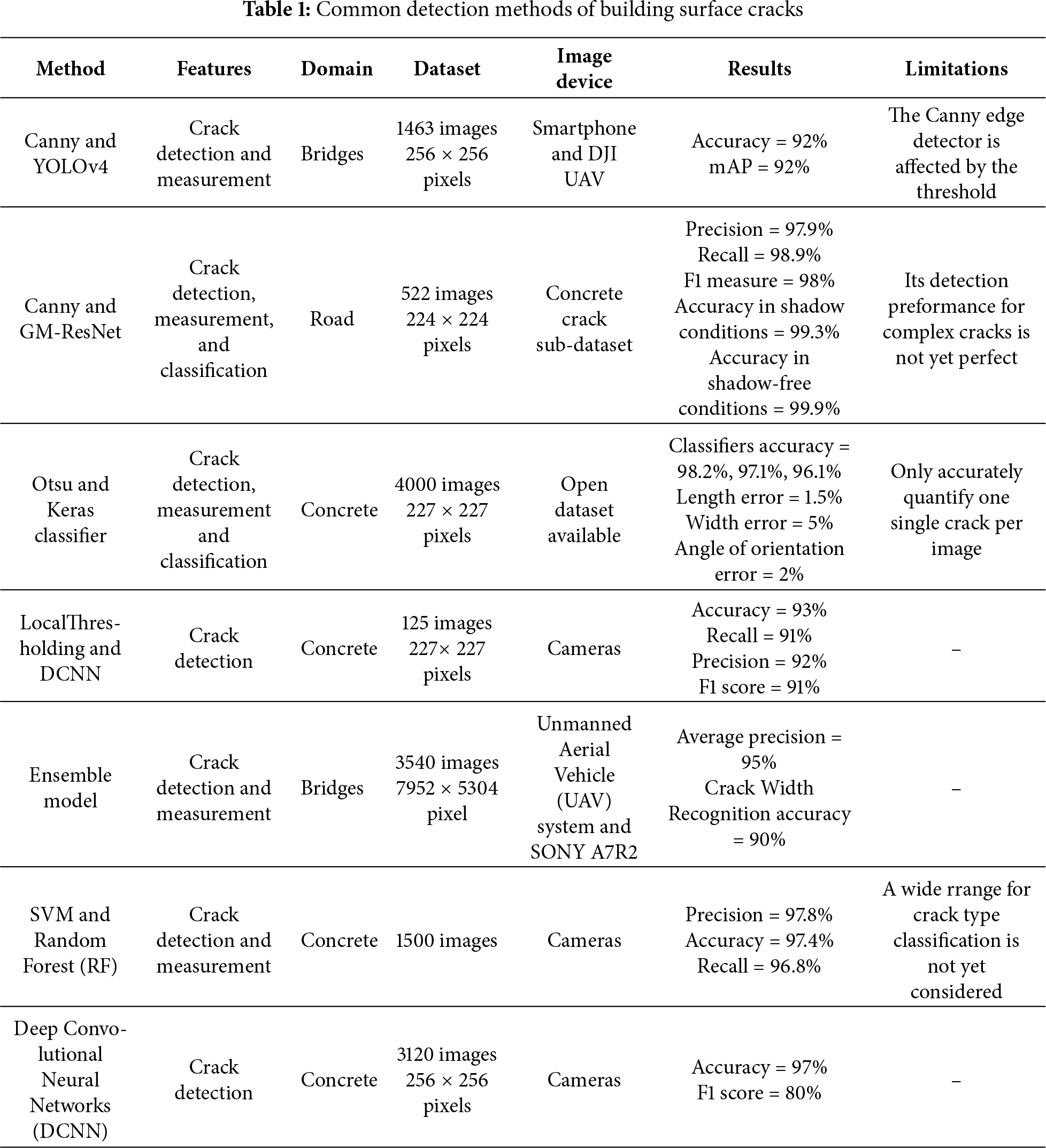
Traditional image processing approaches for crack detection predominantly rely on three core techniques: (i) edge detection [18], (ii) threshold segmentation, and (iii) morphological operations. Among these, edge detection, particularly when enhanced with advanced preprocessing, has demonstrated notable improvements in crack identification. For instance, Li et al. [19] integrated wavelet transform-based denoising with a Canny edge detector, achieving significantly higher accuracy than standalone Canny detection. Furthermore, Ayenu-Prah and Attoh-Okine [20] combined bidimensional empirical mode decomposition (BEMD) with Sobel edge detection, using BEMD for noise suppression before crack feature extraction. However, edge-based methods remain sensitive to illumination artifacts and noise, often necessitating additional preprocessing steps that increase computational overhead. Threshold segmentation techniques, which partition images into distinct regions based on intensity values, offer an alternative for isolating cracks from background textures. Mazni et al. [21] employed Otsu’s thresholding alongside transfer learning to assess concrete degradation, while He and Xu [22] used Otsu preprocessing coupled with YOLOv7 for crack classification, enabling precise detection of repair traces and secondary cracks.
The convergence of conventional crack processing methodologies with deep learning architectures presents a transformative paradigm in structural health monitoring, combining the robustness of engineered feature extraction with the adaptive learning capabilities of neural networks. While traditional methods (e.g., wavelet transforms, edge detection) excel in data preprocessing and preliminary feature identification, deep learning models demonstrate superior performance in learning hierarchical representations of crack morphology through multilayer nonlinear transformations. Recent breakthroughs in sensor fusion technologies have significantly enhanced crack detection reliability. Liu et al. [23] achieved spatiotemporal synchronization of digital photography and Light Detection and Ranging (LiDAR) data through YOLOv5s integration, demonstrating improved accuracy in large-scale structural assessments. Liang et al. [24] developed a dual-modality system combining optical and infrared sensors with C-Net architecture, achieving pixel-level precision in complex environments. Current deep learning implementations fall into three principal categories: (i) image classification [25], (ii) object detection [26], and (iii) semantic segmentation [27]. Gopalakrishnan et al. [28] constructed the CrackFcn model by applying the Fully Convolutional Network to the crack detection task. The model has been shown to enhance crack feature information and improve resolution, thereby enabling effective detection of crack features even in complex backgrounds. Sun et al. [29] enhanced the accuracy of crack detection by improving the DeepLabv3+ model. This was achieved by replacing the standard convolution with a depth-separable convolution, adjusting the convolution expansion rate, assigning channel weights to spatial pyramid modules, and optimizing the feature map selection. The experimental results demonstrate that the method enhances not only the segmentation accuracy and detail retention ability, but also the model’s ability to accurately localize cracks and improve its performance against background interference.
Recent advancements in robotic inspection technology have revolutionized building and infrastructure assessment, driven by improvements in intelligent algorithms, consistent inspection performance, and cost efficiency. Research efforts have focused on developing mobile robotic platforms [30,31] and aerial robotic systems [32] to enhance inspection accuracy and operational efficiency. Since the pioneering introduction of climbing robots for nuclear power plant inspections in 1994 [33], these systems have demonstrated robust adhesion and mobility across diverse surfaces, including vertical, horizontal, curved, and smooth substrates. Among these, vacuum-adsorption climbing robots have gained prominence due to their adaptability to various wall materials, encompassing textured, non-textured, metallic, and glass surfaces [34,35]. Li et al. [36] investigated a vacuum-adsorption climbing robot (Rise-Rover) for structural defect detection in concrete bridge decks. By applying Fast Fourier Transform (FFT) and wavelet transform for feature extraction from impact-echo (IE) signals, they developed a SVM classifier incorporating distance metric learning, achieving reliable defect identification. In a complementary study, Yang et al. [37] introduced an automated inspection system utilizing a climbing robot with foam skirt sealing technology, enabling stable adhesion on both irregular curved surfaces and planar structures. The system’s inspection software facilitates probing, 3D metric reconstruction, and surface measurement, though its computational demands necessitate high-performance hardware. Further applications include Maglietta et al., who deployed a climbing robot with a monocular camera for ship surface corrosion detection via image processing. Zhang et al. [38] employed the YOLOv5s object detection algorithm to train a weld inspection model, enabling weld seam localization and data provision for inspectors. However, this approach is limited to single-type weld recognition and lacks comprehensive defect classification capabilities. A critical challenge in developing cost-effective WCRs lies in optimizing computational efficiency for low-cost hardware while maintaining high detection accuracy. Future research should prioritize the design of lightweight yet robust algorithms to ensure precise crack and defect identification in structural health monitoring applications.
This paper is organized as follows: Section 2 details the WCR system, including prototype and hardware. Section 3 presents the methodology. Section 4 introduces the Canny edge detection method. Section 5 reports experimental results. Section 6 concludes the study.
2 Robotic System Implementation
2.1 Adsorption Principle and Prototype
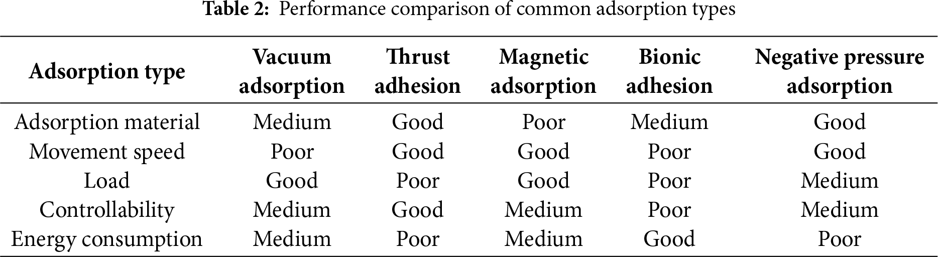
WCRs designed for the detection of surface cracks should possess excellent adsorption properties, ensuring stable operation in high-altitude, complex environments. This would allow it to replace manual structural inspection and maintenance of building surfaces. Table 2 compares common adsorption methods for WCRs [39]. Vacuum adsorption offers simplicity but is limited by poor surface adaptability, control challenges, and vulnerability to air leakage. Magnetic adsorption provides strong attachment but is restricted by the need for magnetically conductive surfaces and heavy magnets. Thrust-based adhesion requires no material-specific building surface but suffers from high noise, low energy efficiency, and weak adhesion. Bionic adhesion is flexible but constrained by surface conditions, reducing speed and load capacity. To meet the diverse needs of WCRs, a negative pressure adsorption system is integrated to ensure reliable attachment to vertical surfaces.
Stable adsorption in WCRs is achieved through a brushless direct current (DC) motor driving a centrifugal impeller, which expels air from the adsorption chamber, creating a pressure differential, as depicted in Fig. 1. This lowers the internal pressure below atmospheric levels, allowing external air to enter through the sealing gap between the sealing skirt and the facade. As the motor continues to operate, an equilibrium is gradually established between the air flow rates of the inlet and outlet air, maintaining stable negative pressure.
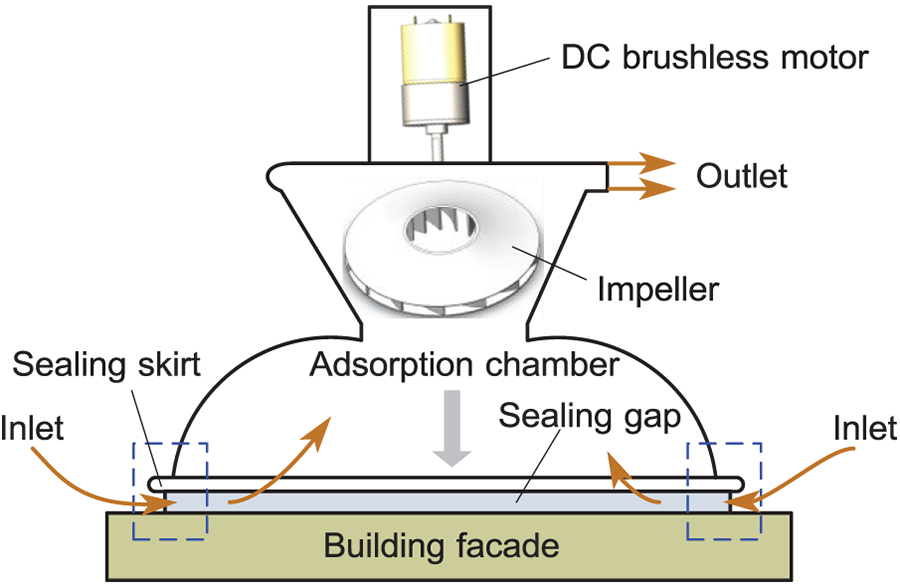
Figure 1: Adsorption principle of WCRs
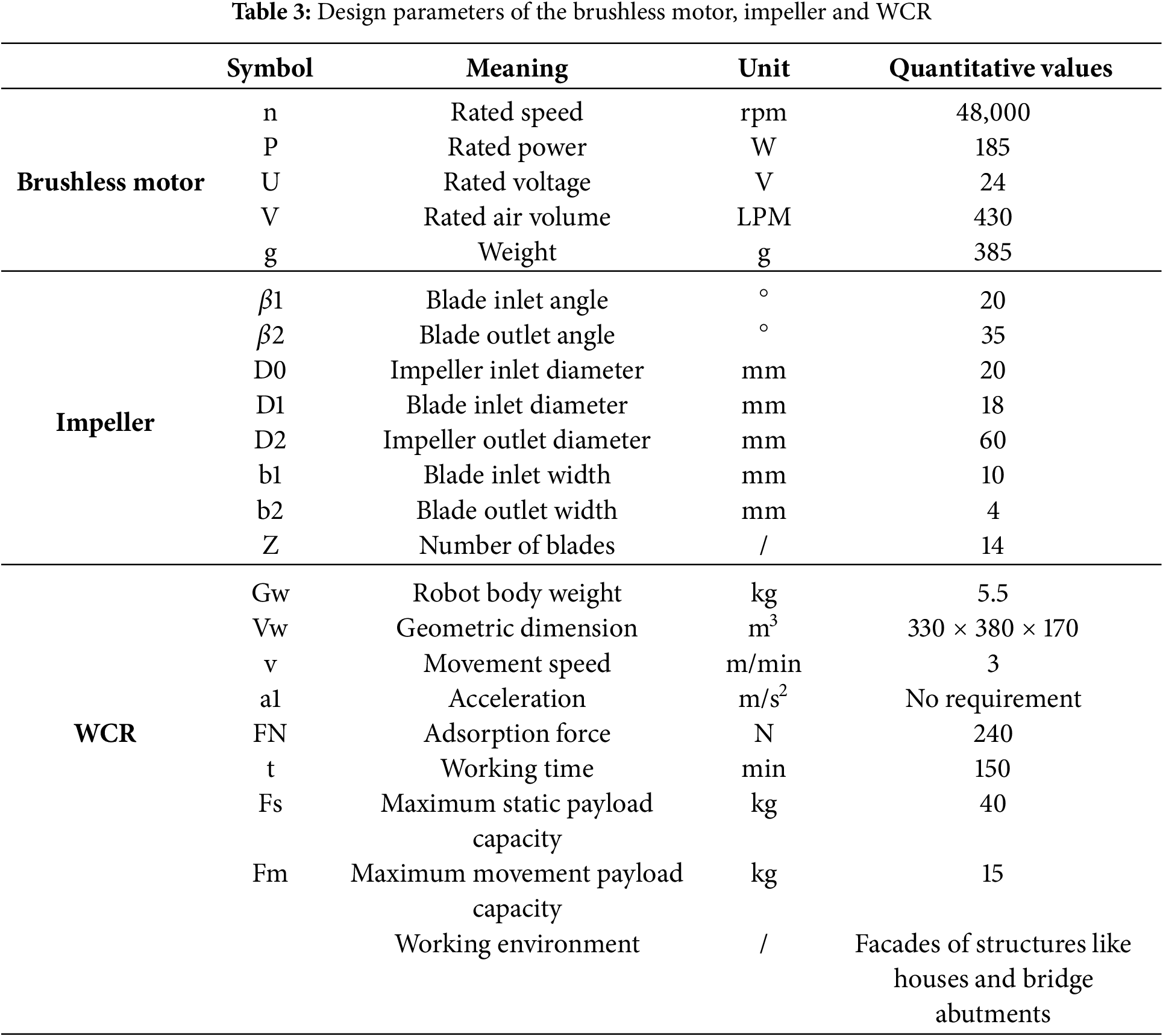
The rated loads of the WCR in this study are set at 40 kg at rest and 15 kg in motion, meeting typical workload requirements. As illustrated in Fig. 2, the WCR prototype consists of two bowl-shaped adsorption chambers, four wheelside motors, four wheels, two DC brushless motors, four height-adjustable motor suspensions, a robot frame, and a housing. Differential steering and movement are achieved by adjusting the four wheelside motors while adhering to the building surface. Additionally, the adsorption system includes a brushless DC motor (purchased from Anchor Drive Technology Co., Ltd., Ningbo, China), centrifugal impeller, air flow housing, adsorption cup support, and flexible adsorption cups. The closed impeller structure prevents air leakage by distributing blades between the front and rear cover plates. The drive system features four drive wheels made of rubber, planetary DC geared motors (12 V, 0.5 A, 18 rpm, 71 kgf·cm torque, 1:369 reduction ratio), and height-adjustable motor suspensions. This suspension system allows for adjustments to the gap between the robot’s adsorption chamber and the facade. Furthermore, the robot frame accommodates batteries, controllers, sensors, cameras, and end actuators. The design parameters of the DC brushless motor, impeller, and WCR technical specifications are summarized in Table 3.
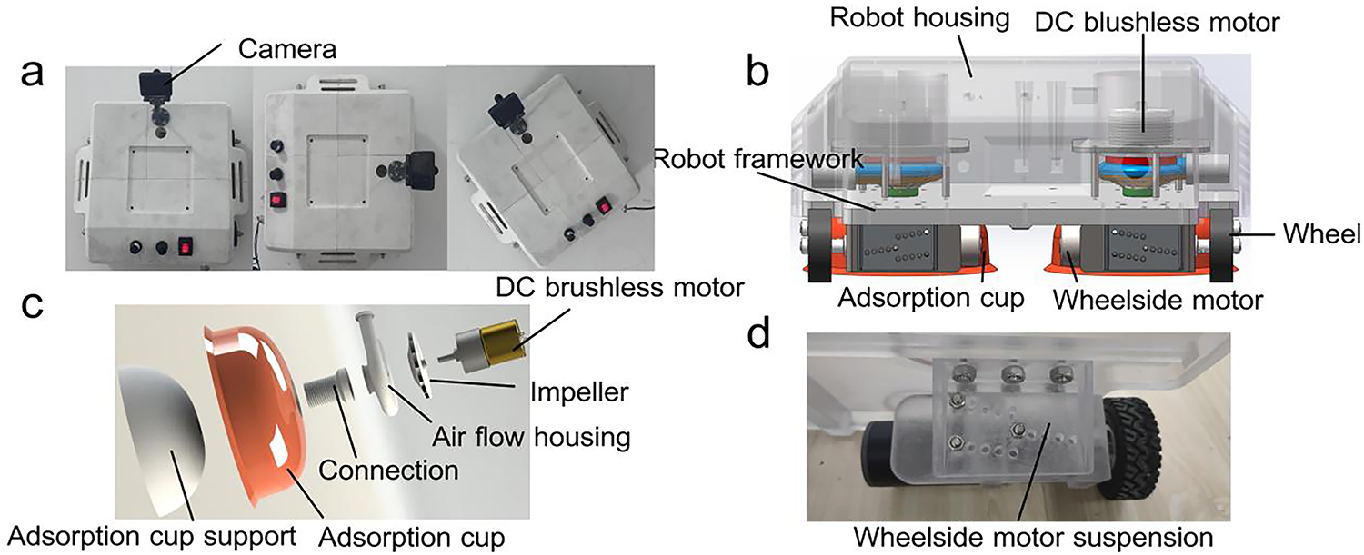
Figure 2: The WCR prototype. (a) WCR in different positions; (b) 3D drawing; (c) Adsorption system; (d) Drive system
The WCR consists of three integrated subsystems: a motion control system, a vision-based crack recognition system, and sensors. One STM32F103C8T6 microcontroller governs locomotion, adhesion, and sensor data fusion, as shown in Fig. 3. Commands from a mobile interface are transmitted via Bluetooth, directing wheel motors for climbing, steering, and bidirectional movement, while a brushless motor regulates adhesive force via real-time pressure feedback. Optical encoders track wheel displacement, an ultrasonic sensor (HC-SR04) maps frontal obstacles, and environmental sensors (DHT11, BMP280) monitor ambient temperature, humidity, and adsorption chamber pressure. Embedded control algorithms dynamically adjust motor speed to stabilize adhesion under varying conditions, enhancing operational robustness and terrain adaptability.
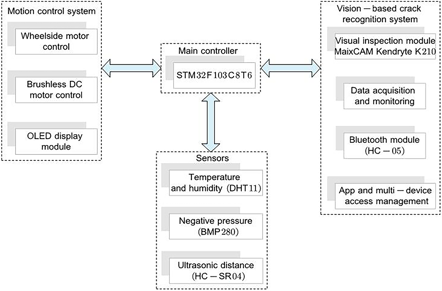
Figure 3: Overall frame diagram of the system
The vision-based crack recognition system is designed to autonomously detect and localize surface fractures in building facades through computational image analysis. By acquiring high-resolution image data and applying advanced processing algorithms, the system enables real-time identification of structural defects, enhancing early damage detection and structural safety assurance.
At the core of this system lies the MaixCAM module, an embedded AIoT vision processor equipped with the Kendryte K210 system-on-chip. This edge-Artificial Intelligence (AI)-optimized chip integrates a dual-core 64-bit RISC-V CPU with a convolutional neural network (CNN) accelerator, enabling efficient execution of lightweight deep learning models. The on-device processing capability eliminates dependency on cloud-based computation, ensuring low-latency, privacy-preserving crack detection without remote server reliance.
This study designs a vision-based crack detection system for wall-climbing robots (WCR) to inspect building surfaces, enabling integrated control of robot locomotion, crack marking, fan speed adjustment, and alarm functions via an upper computer interface. As shown in Fig. 4, the upper computer interface adopts a modular layout with three core functional areas: (1) Image Detection Module: featuring “Crack Marking” and “Alarm” buttons for real-time bounding box annotation and threshold-triggered alerts. (2) Motion Control Module: equipped with four-directional control buttons—forward, left turn, right turn, backward—to achieve precise displacement on vertical walls. (3) Fan Speed Module: offering three speed levels—Speed 1 to Speed 3—to adapt adsorption force to surface roughness. The right section displays dual real-time windows: raw images and detection results with annotated crack boundaries and width parameters, ensuring operability and real-time responsiveness during autonomous inspection.
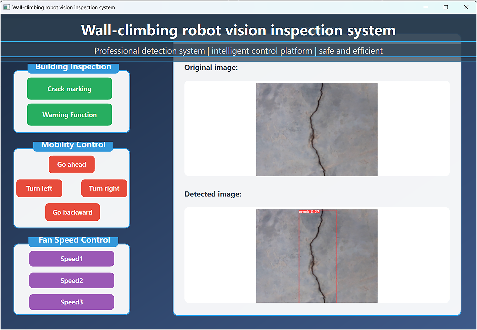
Figure 4: Upper computer control interface of the wall-climbing robot
3.1 Dataset Acquisition and Preparation
Image data were collected from multiple buildings in Wuhan, China, using the MaixCAM equipped with an OS04A10 4-megapixel CMOS sensor, mounted on the WCR for vertical wall imaging. To standardize the dataset, raw images were cropped and resized to 320 × 240 pixels, corresponding to a physical coverage of 150 × 150 mm2 per image, achieving a spatial resolution of 3.0 × 3.0 mm2/pixel.
The final annotated dataset consists of 1453 images, partitioned into training (1292 images) and validation (161 images) subsets at an 8:1 ratio. Crack annotations include three morphologically distinct categories: transverse, longitudinal, and mesh-type cracks, with 395 samples per class. To enhance model robustness, the dataset incorporates negative samples containing confounding features such as wall stains, surface textures, and material irregularities to mitigate false-positive detections. Representative samples are illustrated in Fig. 5, and the crack detection pipeline is shown in Fig. 6.
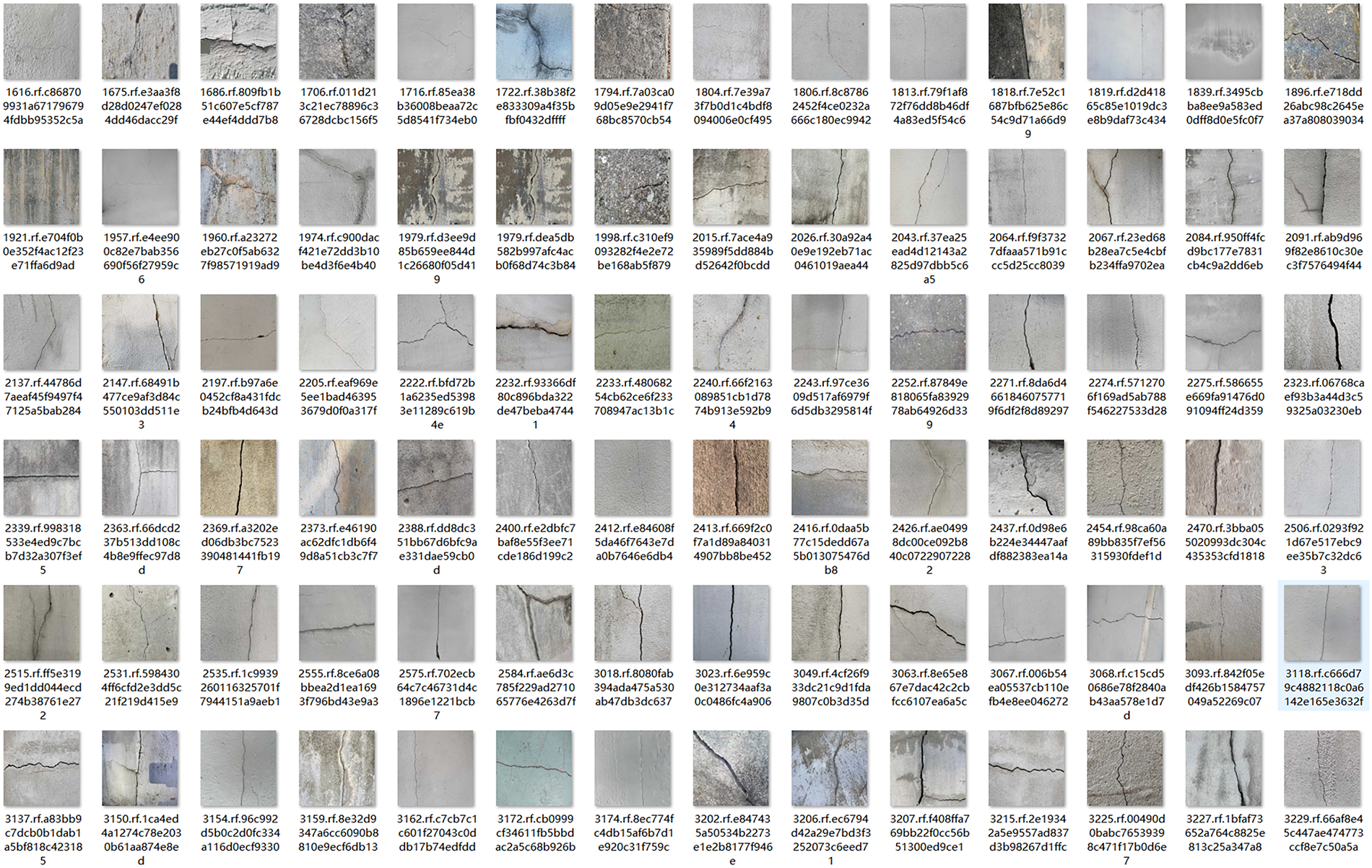
Figure 5: Representative samples
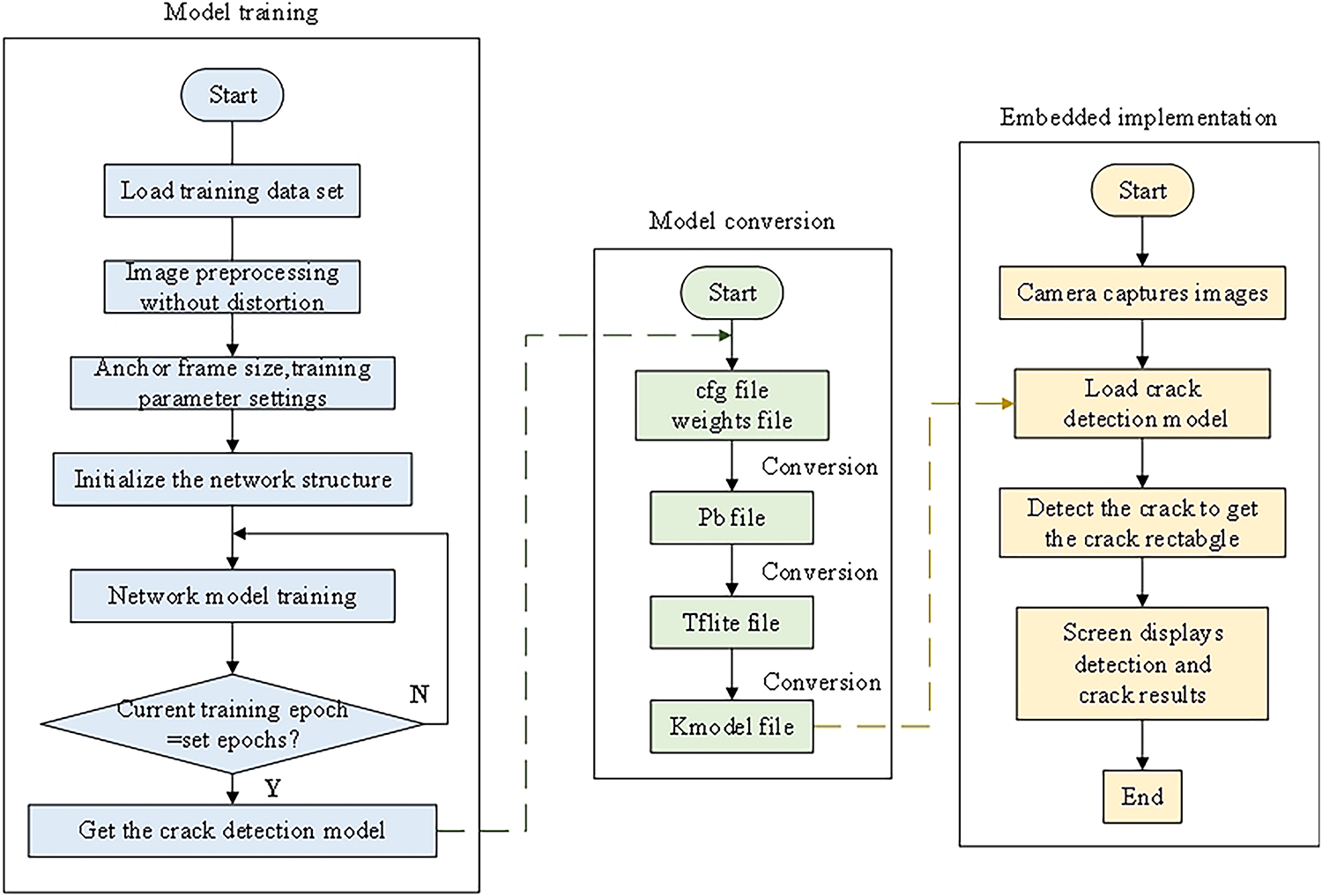
Figure 6: Crack detection pipeline
3.2 Model Building and Training
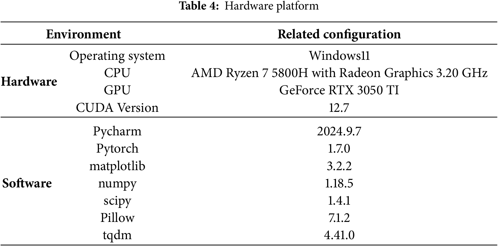
The model training was performed on a hardware platform equipped with an AMD Ryzen 7 5800H processor (3.20 GHz, with integrated Radeon Graphics) and an NVIDIA GeForce RTX 3050 Ti discrete GPU (6 GB VRAM). The system was supported by 16 GB of RAM and operated on Windows 11 with CUDA 12.7 for GPU acceleration, as shown in Table 4.
The crack detection model was trained for 300 iterations using YOLOv5s.pt pre-trained weights. Training employed a batch size of 32, a minimum bounding box size of 10 pixels, and an initial learning rate of 0.01 with momentum (0.975) and weight decay (0.0005).
The crack dataset label distribution revealed that most annotations cluster in the upper-right region of width-height space, indicating a predominance of large cracks. Thus, our method prioritized large-target detection. Training metrics showed synchronous convergence of box loss (0.04) and object loss (0.02) for training and validation sets (difference < 15%), confirming improved localization without overfitting. Classification loss remained stable (0.02~0.03, ±5% fluctuation), while precision and recall exceed 95% after 200 epochs. The mAP@0.5 stabilizes near 0.95, reflecting robust detection accuracy. Precision for the “crack” class peaked at 1.0 (confidence ≥ 0.694), while recall similarly converged to 1. Moreover, the optimized model achieved 35 FPS at 320 × 240 resolution, balancing real-time performance with high accuracy in complex environments.
The Canny edge detection algorithm is a classic multi-stage image processing technique for edge detection, characterized by its low computational resource requirements and high operational efficiency. Compared to methods such as threshold segmentation and deep learning, the Canny algorithm is simpler to implement, making it well-suited for real-time processing. It operates with low power consumption and high speed, enabling rapid and accurate extraction of crack edges while minimizing background interference. These attributes make it ideally suited for wall-climbing robots that demand real-time performance, low power consumption, and compatibility with resource-constrained embedded platforms.
The methodology is implemented as follows:
1. Image smoothing: Gaussian filtering is applied to suppress noise and minimize high-frequency interference, ensuring cleaner input for subsequent processing.
2. Gradient computation: The Sobel operator is employed to determine gradient magnitude and direction, enabling the preliminary extraction of potential edge locations.
3. Non-maximum suppression: A suppression mechanism is utilized to retain only local maxima along the gradient direction, refining the detected edges and eliminating redundant information.
4. Dual thresholding: Edge regions are classified into strong, weak, and non-edge pixels based on predefined high and low thresholds, effectively reducing noise.
5. Edge linking: Weak edges are connected to strong edges to ensure continuity and structural integrity, yielding enhanced crack contours.
In the domain of crack detection, this study presents a novel approach to enhance the precision of crack localization by integrating the YOLOv5s model with the Canny edge detection algorithm. While YOLOv5s effectively identifies crack regions, the incorporation of the Canny algorithm-a well-established edge detection technique-further refines crack boundaries through a sequence of structured and rigorous image processing steps, including image smoothing, gradient computation, non-maximum suppression, dual thresholding, and edge linking (see Fig. 7). This process significantly enhances edge clarity, accentuates fine structural details, and improves localization accuracy.
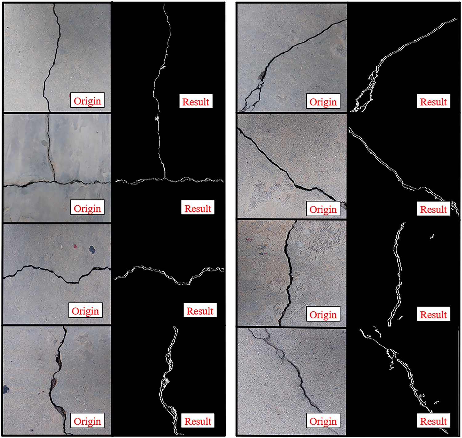
Figure 7: Flow chart of classical Canny operator
By systematically implementing these processing steps, the Canny algorithm effectively suppresses noise artifacts, sharpens crack boundaries, and improves the visibility of fine structural features. As illustrated in Fig. 8, this approach effectively mitigates the limitations of YOLOv5s in crack boundary delineation, significantly improving localization accuracy and enabling precise feature extraction. Furthermore, the integration of Canny edge detection enhances the robustness and adaptability of the detection framework, ensuring reliable performance across diverse and complex environmental conditions.
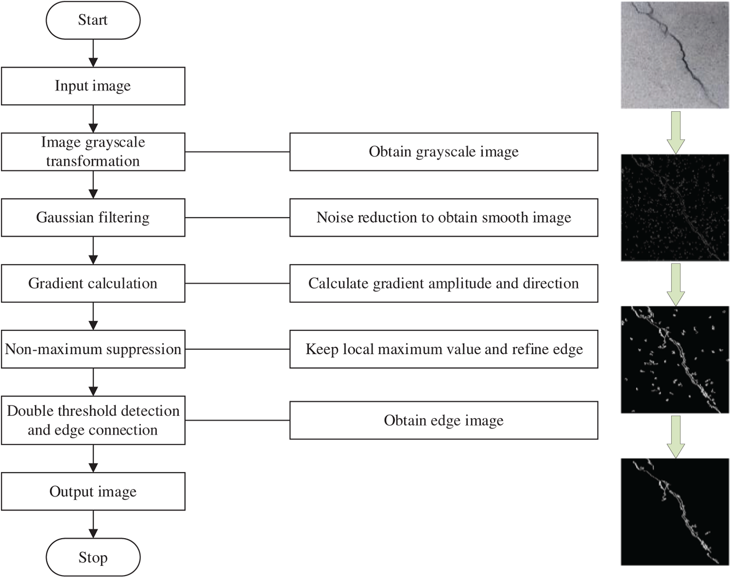
Figure 8: Canny edge detection and identification of crack renderings
4.1 Gaussian Filtering for Image Smoothing
During the imaging process, image noise inevitably arises due to factors such as component characteristics, circuit architecture, and signal transmission. This noise degrades image quality and compromises edge detection performance by introducing spurious edge artifacts. To address this, the Canny edge detection algorithm initially employs a Gaussian filter for noise suppression prior to subsequent processing. The smoothing operation utilizes the first derivative of a two-dimensional Gaussian function, with the filtered image denoted as G(x, y). The two-dimensional Gaussian function is mathematically expressed as:
where x and y represent the pixel coordinates in the horizontal and vertical directions, respectively, and σ denotes the standard deviation that determines the degree of smoothing. When σ is small, the detection accuracy remains relatively high but the filtering effect is limited; conversely, a larger σ significantly improves noise suppression at the expense of edge blurring, consequently reducing edge localization precision. The gradient vector can be expressed as:
To improve the computational efficiency of the Canny algorithm, the two-dimensional convolution kernel ∇G(x, y) is decomposed into two one-dimensional filters, expressed as follows:
where k represents a parameter indicating the size of the convolution kernel or the length of the filter. Convolve these two templates with the image f(x, y) to obtain Ex and Ey:
where
4.2 Gradient Amplitude and Gradient Direction
To perform edge detection, it is necessary to obtain the gradient information of the image. The Canny algorithm employs first-order differential operators to compute the gradient magnitude and direction for each pixel. The gradient magnitude reflects the degree of brightness variation at a given pixel in the image, while the gradient direction indicates the orientation of this variation. Gradient calculations are performed separately in the horizontal and vertical directions. The partial derivative matrices in these two orthogonal directions can be mathematically expressed as:
Derivative computation is highly sensitive to noise. Performing edge detection solely based on horizontal and vertical gradients may lead to significant false detection. To address this, the gradient magnitude and orientation at each pixel are calculated through Cartesian-to-polar coordinate transformation. Specifically, the gradient magnitude (G) and direction (θ) are computed using the L2-norm as shown in Eqs. (7) and (8):
If the gradient magnitude of pixel M(x, y) is greater than or equal to the gradient magnitudes of its two adjacent pixels along the gradient direction, then this pixel can be identified as a potential edge point.
4.3 Non-Maximum Suppression (NMS)
To achieve more precise edge localization in building crack images, a refinement process is implemented to identify edge points with the most significant amplitude variations. The Non-Maximum Suppression (NMS) algorithm operates through the following procedure: For each pixel M(x, y), the algorithm compares its gradient magnitude with neighboring pixels along the gradient direction. If M(x, y) does not represent a local maximum in its gradient neighborhood, its intensity value is suppressed to zero. Conversely, when M(x, y) demonstrates the maximum gradient magnitude within its local neighborhood, it is preserved as a potential edge point. This selective suppression mechanism effectively eliminates spurious edge responses while maintaining geometrically accurate edge contours.
4.4 Dual-Threshold Detection and Edge Connection
The proposed edge detection pipeline achieves robust identification of genuine edges, though residual spurious edges may persist following initial processing. To enhance boundary delineation accuracy, we implement a hysteresis thresholding mechanism employing dual threshold values (T_high and T_low) for selective edge preservation. The algorithm processes the non-maximum suppressed gradient image as follows: pixels exhibiting gradient magnitudes exceeding T_high are classified as strong edges and retained unconditionally; those below T_low are rejected as noise; while intermediate-gradient pixels undergo connectivity analysis—retained only if exhibiting 8-neighbor connectivity to strong edge pixels, otherwise discarded. This selective thresholding strategy effectively bridges discontinuous edge segments while suppressing noise artifacts, thereby preserving topological continuity of structural boundaries. The iterative edge linking process successfully reconstructs fragmented edge contours, yielding a complete and coherent edge representation of the input image.
The WCR equipped with an OS04A10 camera (Maixcam module) was deployed to autonomously traverse vertical building surfaces, capturing high-resolution images of structural cracks (see Fig. 9). For real-time crack detection, a hybrid approach combining the YOLOv5s convolutional neural network (CNN) and a lightweight Canny edge detection algorithm was implemented. The system demonstrated robust performance in identifying cracks of diverse widths and morphologies, achieving a processing speed sufficient for real-time applications (see Fig. 10).
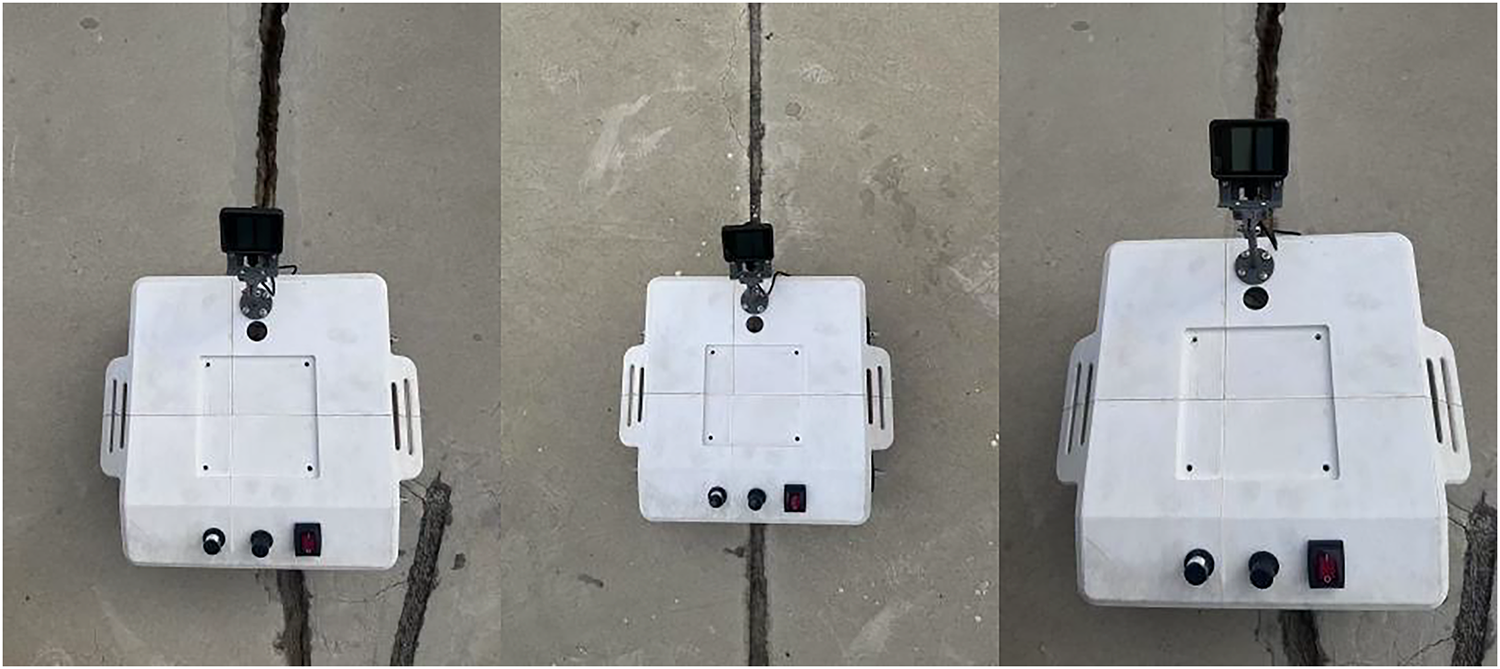
Figure 9: Real-time crack image acquired by WCR on the vertical building surface
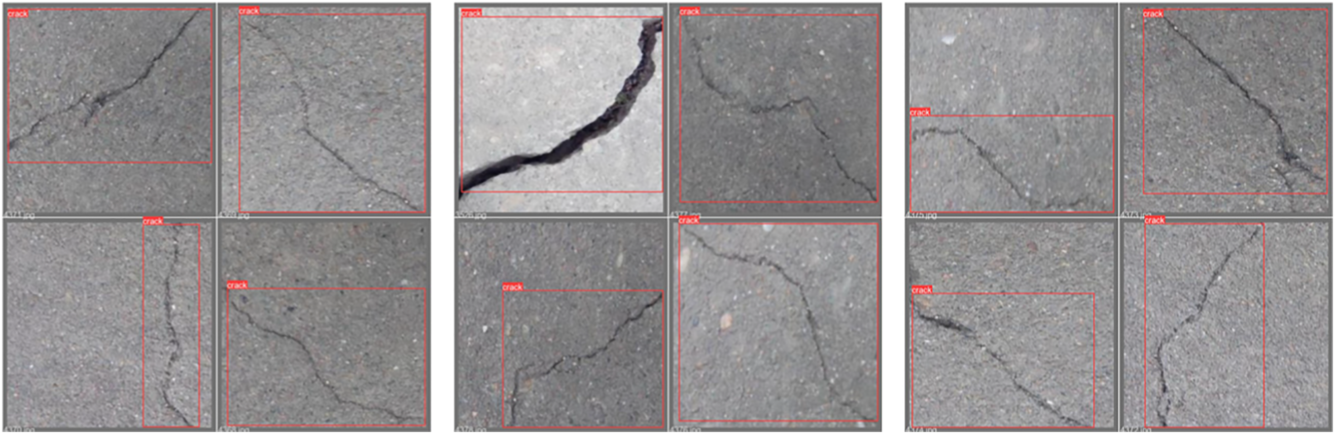
Figure 10: YOLOv5s crack identification rendering
Quantitative analysis of experimental data revealed a crack recognition accuracy exceeding 90%. The YOLOv5s model, leveraging deep CNN-based feature extraction and post-processing, precisely localized cracks and annotated them with bounding boxes. These results confirm the system’s high reliability and accuracy in structural health monitoring, even in complex environments, making it a viable solution for engineering applications.
5.2 Experimental Results of Different Edge Detectors
To validate the impact of the Canny edge enhancement module and different edge detection algorithms on crack detection performance, four comparative experiments were designed based on the original YOLOv5s network: (1) YOLOv5s only; (2) YOLOv5s + Canny; (3) YOLOv5s + Sobel; (4) YOLOv5s + Laplacian. The experiments were conducted on a unified dataset (1453 images containing concrete, brick, and stone samples) and an embedded device (MaixCAM), with evaluation metrics including precision (P), recall (R), mAP, and FPS, as shown in Table 5.
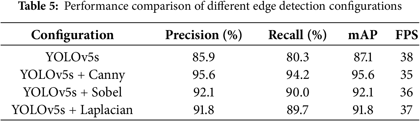
Key observations from the table: (1) The original YOLOv5s algorithm achieved a detection accuracy of 89.2%, a recall rate of 87.5%, and an FPS of 38, which can basically accomplish the detection task but with suboptimal performance. (2) After incorporating the Canny module into the backbone model, compared to YOLOv5s alone, mAP improved by 10.3%, while precision and recall increased by 9.7% and 13.9%, respectively. This demonstrates that Canny outperforms Sobel and Laplacian in noise suppression and preserving complete crack edges. (3) Comparison with other edge detectors: Sobel and Laplacian achieved mAP scores of 92.1% and 91.8%, respectively, both lower than Canny’s 95.6%. This is because Sobel is sensitive to illumination variations, while Laplacian tends to produce double-edge effects. In contrast, the Canny algorithm effectively connects discontinuous edges, such as fine cracks under the interference of brick surface textures.
5.3 Experimental Results of Different Model Architectures
To further validate the rationality of the proposed method, this section designs two sets of comparative experiments: (1) comparison with end-to-end segmentation models (U-Net, DeepLabV3+); (2) comparison with lightweight object detection models (MobileNetV3). The experiments were conducted on a unified dataset (1453 images containing concrete, brick, and stone samples) and an embedded device (MaixCAM with ARM Cortex-A72 architecture). Evaluation metrics include mAP (0.5:0.95), FPS, model size, and crack width measurement error (using manual annotations as ground truth, calculated as pixel-level root mean square error). The results are shown in Table 6.
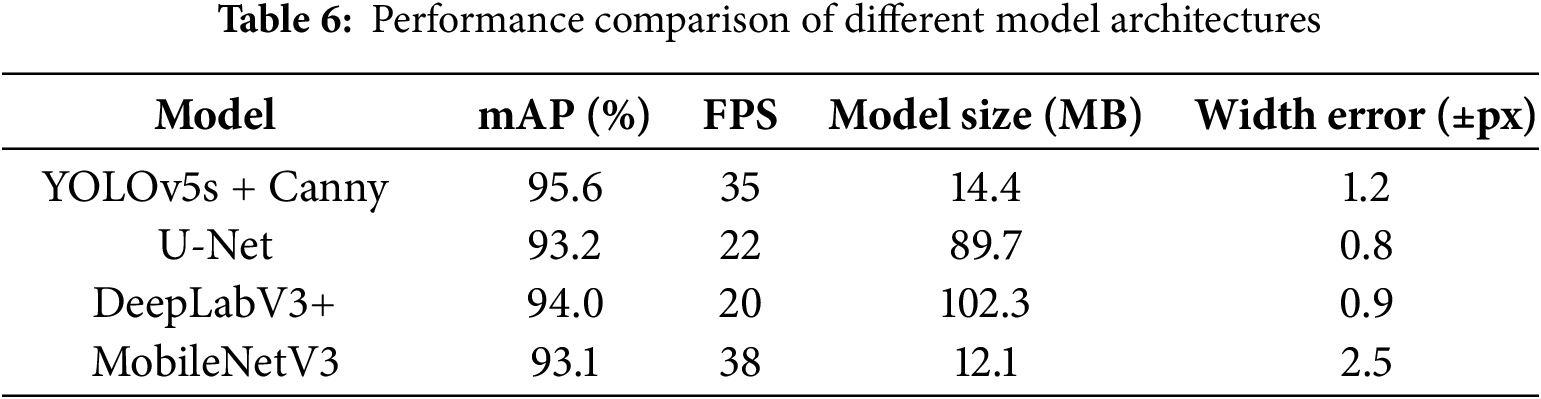
Experimental setup: Segmentation models used a unified input size of 640 × 640; MobileNetV3 adopted officially pre-trained weights; Width error was calculated using pixel-level RMSE from 200 manually annotated cracks.
As shown in Table 6, the method demonstrates significant advantages across multiple performance metrics when compared to alternative approaches. Compared to segmentation models, our solution achieves higher detection accuracy with a 95.6% mAP score, surpassing both U-Net’s 93.2% and DeepLabV3+’s 94.0%. The system maintains efficient real-time performance at 35 FPS, representing a 37% to 43% speed improvement over segmentation models while requiring only 15% to 17% of their model size. In crack width measurement, our ±1.2 pixel accuracy approaches the precision of segmentation models. When compared to MobileNetV3, our method delivers superior 2.5% higher mAP despite a marginally lower frame rate. The decision against using segmentation models stems from their computational intensity, limited to 20–22 FPS on embedded platforms, and their tendency to overfit smaller datasets due to requiring pixel-level annotations.
Experimental results reveal significant limitations: segmentation models achieve only 20–22 FPS on embedded devices (37% slower than ours), lacking real-time capability with high computational costs, while lightweight MobileNetV3 shows inferior crack detection accuracy despite faster inference, coupled with deployment complexities. Our method demonstrates comprehensive advantages in speed, accuracy and deployment convenience.
5.4 Experimental Results of Different Illuminations
In this section, experimental testing was conducted to evaluate the crack recognition performance of the WCR under different illuminations, with the aim of assessing its adaptability in complex lighting environments. To approximate actual application scenarios, the experiments were designed and simulated with three typical illuminations: strong light, low light and shadow environment, to measure the accuracy and response speed of the WCR’s crack recognition under different illuminations, respectively.
The experiments were conducted within a laboratory environment by adjusting the intensity and irradiation angle of the controllable light source (see Fig. 11): (1) Strong light: simulating direct sunlight at noon, with a illumination of 1000 lux; (2) Low light: simulating cloudy or dusk environments, with a illumination of 200 lux; (3) Shadow condition: simulating local shadows on the surface of a building, with the illumination set to 50 lux. A total of 100 image samples containing cracks were collected under each illumination, and the accuracy of crack identification and the average processing time were recorded to evaluate the robustness and detection efficiency of the system under different illuminations.
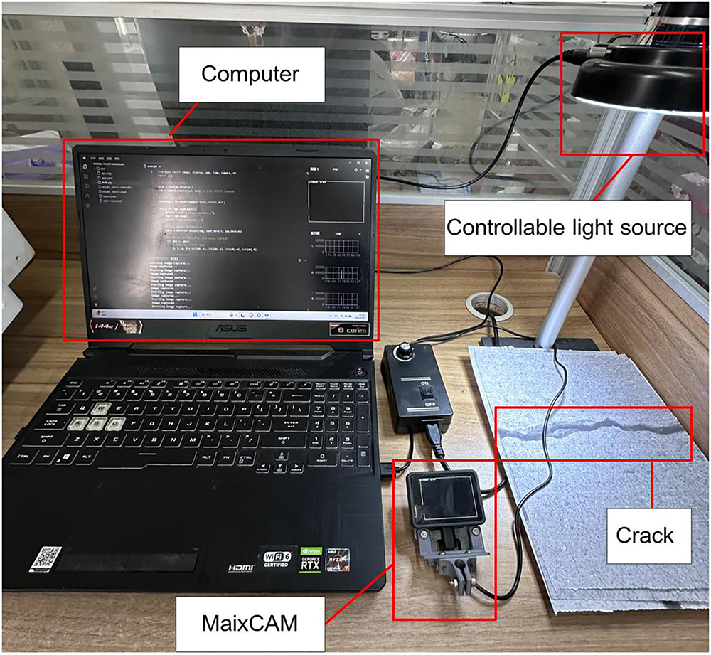
Figure 11: Crack identification under different illuminations
As demonstrated in Fig. 12, the performance of the WCR crack identification system is significantly influenced by the lighting environments. The experimental findings demonstrate that the highest attainable accuracy of 95.6% in crack identification is achieved under conditions of strong light. This superior performance can be attributed to the fact that sufficient light enhances the clarity of the crack edges and improves the image quality, thereby enhancing the detection accuracy. Conversely, under low light conditions, the identification accuracy exhibits a slight decline, reaching 92.1%. This decline in performance can be attributed to the blurring of image details caused by insufficient lighting, which compromises the clarity of crack edges and consequently affects the effectiveness of detection. The lowest identification accuracy, 88.3%, was found under shadow conditions. The presence of localized shadows led to a reduction in image contrast, which hindered the clear capture of crack edges and consequently impacted the detection accuracy.
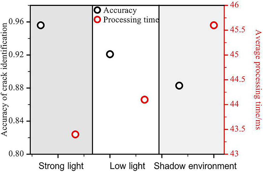
Figure 12: Crack identification results under different illuminations
5.5 Experimental Results of Different Crack Types
To evaluate the generalization capability of the crack identification system for different crack types, this section conducts experimental tests on three types of typical defects, namely transverse cracks, longitudinal cracks and mesh cracks. Crack images of concrete, brick walls and stone surfaces are selected for the experiments, with each type of crack containing 100 sample images. The system’s identification accuracy and stability of different crack patterns are then tested.
The definition of the three types of cracks is based on manual label criteria: (1) Transverse crack: a horizontal or near-horizontal linear defect; (2) Longitudinal crack: a vertical or near-vertical linear defect; and (3) Mesh crack: a complex branching structure formed by multi-directional cross-cracks (see Fig. 13). The performance of the system in recognizing the three types of cracks is demonstrated in Fig. 14.
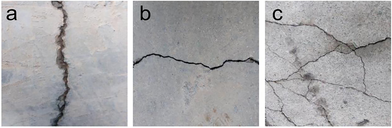
Figure 13: Fracture diagram of three typical defects: (a) Transverse crack: Horizontal/near-horizontal linear defect; (b) Longitudinal crack: Vertical/near-vertical linear defect; (c) Mesh crack: Multi-directional cross-cracks forming branched structures
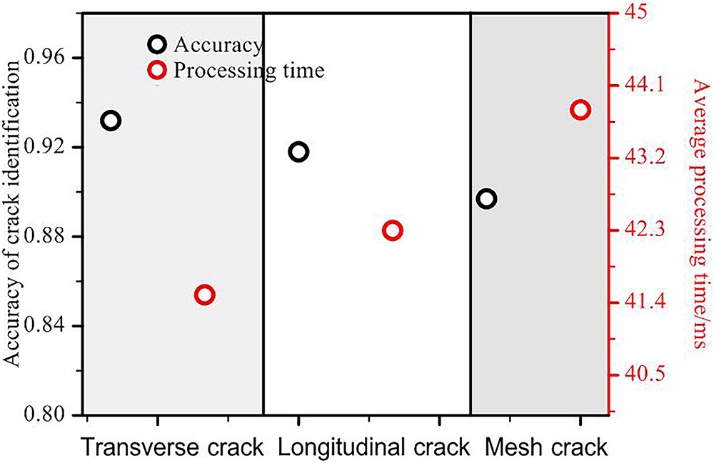
Figure 14: Crack identification results under different crack types
The experimental findings indicate that both transverse cracks and longitudinal cracks exhibit identification accuracies of 93.2% and 91.8%, respectively, attributable to their more regular structure and continuous edges. Conversely, the identification accuracy of mesh cracks exhibited a marginal decline to 89.7%, attributable to their intricate branching geometry and diminished local contrast. The system’s processing time remained consistent at 41.5~43.8 ms for all three types of cracks, indicating its capability to meet real-time requirements while maintaining high identification accuracy. This finding validates the system’s capacity to optimize the balance between detection accuracy and computational efficiency.
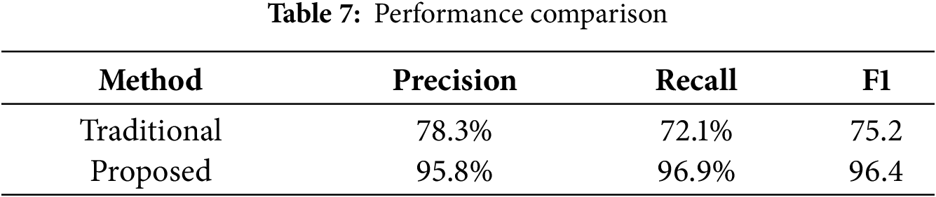
To quantify the performance improvement, we conducted comparative experiments against traditional methods (Otsu thresholding + SVM classifier) using a standardized test set of 135 images with complex backgrounds (concrete/brick/stone surfaces) under controlled illumination (800 ± 50 lux). The results are shown in Table 7.
The comprehensive performance metric F1-score was calculated as:
The quantitative results demonstrate:
The absolute improvement was computed as:
The relative improvement percentage was derived through:
After 5-fold cross-validation adjustment to eliminate overfitting bias:
This study presents an advanced vision-based crack detection system for WCRs that integrates the YOLOv5s deep learning architecture with Canny edge enhancement to achieve robust defect identification in challenging environments. The robotic platform, featuring a dual-chamber negative pressure adsorption mechanism and differential drive system, demonstrates exceptional operational stability with a 40 kg payload capacity and 3 m/min vertical climbing speed. Real-time processing is enabled through an embedded vision module (MaixCAM), combining computational efficiency with field-deployable practicality.
Quantitative evaluation reveals superior detection performance, with precision (95.8%), recall (96.9%), and mAP50 (95%) metrics establishing new benchmarks for automated structural inspection. The system maintains high accuracy across illumination variations (95.6% at 1000 lux to 88.3% at 50 lux) and effectively discriminates crack morphologies (93.2%, 91.8%, and 89.7% for horizontal, vertical, and mesh cracks, respectively). A 17.3% improvement over conventional methods highlights the technological advance represented by this integrated approach.
These findings demonstrate a paradigm shift in infrastructure maintenance, where autonomous robotic systems can now provide reliable, quantitative structural assessments without human intervention. The solution’s combination of algorithmic sophistication and hardware efficiency suggests immediate applicability across civil infrastructure networks. Future development should focus on expanding the system’s operational envelope to address more diverse defect types and extreme environmental conditions.
Acknowledgement: Not applicable.
Funding Statement: The work described in this paper was supported by the Research Project on Postgraduate Teaching Reform from Hubei Education Department (2024289).
Author Contributions: study conception and design: Xianghui Li, Libo Pan, Fancong Zeng, Zhijiang Zuo, Xin Fu; draft manuscript preparation and data collection: Xianghui Li; analysis and interpretation of results: Xianghui Li, Libo Pan; check and supervision: Xianghui Li, Fancong Zeng. All authors reviewed the results and approved the final version of the manuscript.
Availability of Data and Materials: The data supporting the results reported in the paper can be accessed from the first author or the corresponding author. We are actively preparing the complete dataset (including raw images, annotations, and metadata) for public release through Figshare upon manuscript acceptance, with anticipated availability.
Ethics Approval: Not applicable.
Conflicts of Interest: The authors declare no conflicts of interest to report regarding the present study.
References
1. Jiang Z, Wang M, Zhao Z, Li YC, Xu YD. Review on the development status and key technologies of wall-climbing robot. Packag Eng. 2023;44(12):29–38. (In Chinese). doi:10.19554/j.cnki.1001-3563.2023.12.003. [Google Scholar] [CrossRef]
2. Nagaya K, Yoshino T, Katayama M, Murakami I, Ando Y. Wireless piping inspection vehicle using magnetic adsorption force. IEEE/ASME Trans Mechatron. 2012;17(3):472–9. doi:10.1109/TMECH.2011.2182201. [Google Scholar] [CrossRef]
3. Yangí L, Yang G, Liu Z, Chang Y, Jiang B, Awad Y, et al. Wall-climbing robot for visual and GPR inspection. In: Proceedings of the 2018 13th IEEE Conference on Industrial Electronics and Applications (ICIEA); 2018 May 31–Jun 2; Wuhan, China. p. 1004–9. doi:10.1109/ICIEA.2018.8397858. [Google Scholar] [CrossRef]
4. Choi Y, Park HW, Mi Y, Song S. Crack detection and analysis of concrete structures based on neural network and clustering. Sensors. 2024;24(6):1725. doi:10.3390/s24061725. [Google Scholar] [PubMed] [CrossRef]
5. Yahya S, Elsanary H, Hassan M, Ali A. An improved edge detection method for image analysis in diverse domains. Aswan Sci Technol Bull. 2024;2(2):11–29. doi:10.21608/astb.2024.310816.1004. [Google Scholar] [CrossRef]
6. Kovalskyi S, Koval V. Comparison of image processing techniques for defect detection. CEUR Workshop Proc. 2024;3716:158–67. [Google Scholar]
7. Flah M, Suleiman AR, Nehdi ML. Classification and quantification of cracks in concrete structures using deep learning image-based techniques. Cem Concr Compos. 2020;114:103781. doi:10.1016/j.cemconcomp.2020.103781. [Google Scholar] [CrossRef]
8. Su H, Wang X, Han T, Wang Z, Zhao Z, Zhang P. Research on a U-Net bridge crack identification and feature-calculation methods based on a CBAM attention mechanism. Buildings. 2022;12(10):1561. doi:10.3390/buildings12101561. [Google Scholar] [CrossRef]
9. Loutridis S, Douka E, Trochidis A. Crack identification in double-cracked beams using wavelet analysis. J Sound Vib. 2004;277(4–5):1025–39. doi:10.1016/j.jsv.2003.09.035. [Google Scholar] [CrossRef]
10. Peng X, Zhong X, Zhao C, Chen A, Zhang T. A UAV-based machine vision method for bridge crack recognition and width quantification through hybrid feature learning. Constr Build Mater. 2021;299:123896. doi:10.1016/j.conbuildmat.2021.123896. [Google Scholar] [CrossRef]
11. Tabatabaei SAH, Delforouzi A, Khan MH, Wesener T, Grzegorzek M. Automatic detection of the cracks on the concrete railway sleepers. Int J Patt Recogn Artif Intell. 2019;33(9):1955010. doi:10.1142/s0218001419550103. [Google Scholar] [CrossRef]
12. Park MJ, Kim J, Jeong S, Jang A, Bae J, Ju YK. Machine learning-based concrete crack depth prediction using thermal images taken under daylight conditions. Remote Sens. 2022;14(9):2151. doi:10.3390/rs14092151. [Google Scholar] [CrossRef]
13. Wang W, Hu W, Wang W, Xu X, Wang M, Shi Y, et al. Automated crack severity level detection and classification for ballastless track slab using deep convolutional neural network. Autom Constr. 2021;124:103484. doi:10.1016/j.autcon.2020.103484. [Google Scholar] [CrossRef]
14. Dorafshan S, Thomas RJ, Maguire M. Comparison of deep convolutional neural networks and edge detectors for image-based crack detection in concrete. Constr Build Mater. 2018;186:1031–45. doi:10.1016/j.conbuildmat.2018.08.011. [Google Scholar] [CrossRef]
15. Chaiyasarn K, Buatik A, Mohamad H, Zhou M, Kongsilp S, Poovarodom N. Integrated pixel-level CNN-FCN crack detection via photogrammetric 3D texture mapping of concrete structures. Autom Constr. 2022;140:104388. doi:10.1016/j.autcon.2022.104388. [Google Scholar] [CrossRef]
16. Li S, Zhao X, Zhou G. Automatic pixel-level multiple damage detection of concrete structure using fully convolutional network. Comput Aided Civ Infrastruct Eng. 2019;34(7):616–34. doi:10.1111/mice.12433. [Google Scholar] [CrossRef]
17. Zheng X, Zhang S, Li X, Li G, Li X. Lightweight bridge crack detection method based on SegNet and bottleneck depth-separable convolution with residuals. IEEE Access. 2021;9:161649–68. doi:10.1109/ACCESS.2021.3133712. [Google Scholar] [CrossRef]
18. Wang J, He X, Shao F, Lu G, Cong H, Jiang Q. A real-time bridge crack detection method based on an improved inception-resnet-v2 structure. IEEE Access. 2021;9:93209–23. doi:10.1109/ACCESS.2021.3093210. [Google Scholar] [CrossRef]
19. Li X, Xu X, He X, Wei X, Yang H. Intelligent crack detection method based on GM-ResNet. Sensors. 2023;23(20):8369. doi:10.3390/s23208369. [Google Scholar] [PubMed] [CrossRef]
20. Ayenu-Prah A, Attoh-Okine N. Evaluating pavement cracks with bidimensional empirical mode decomposition. EURASIP J Adv Signal Process. 2008;2008(1):861701. doi:10.1155/2008/861701. [Google Scholar] [CrossRef]
21. Mazni M, Husain AR, Shapiai MI, Ibrahim IS, Anggara DW, Zulkifli R. An investigation into real-time surface crack classification and measurement for structural health monitoring using transfer learning convolutional neural networks and Otsu method. Alex Eng J. 2024;92:310–20. doi:10.1016/j.aej.2024.02.052. [Google Scholar] [CrossRef]
22. He Z, Xu W. Deep learning and image preprocessing-based crack repair trace and secondary crack classification detection method for concrete bridges. Struct Infrastruct Eng. 2024:1–17. doi:10.1080/15732479.2024.2330702. [Google Scholar] [CrossRef]
23. Liu J, Lv C, Lu G, Zhao Z, Han B, Guo F, et al. Lightweight defect detection equipment for road tunnels. IEEE Sens J. 2024;24(4):5107–21. doi:10.1109/jsen.2023.3320816. [Google Scholar] [CrossRef]
24. Liang H, Qiu D, Ding KL, Zhang Y, Wang Y, Wang X, et al. Automatic pavement crack detection in multisource fusion images using similarity and difference features. IEEE Sens J. 2024;24(5):5449–65. doi:10.1109/JSEN.2023.3267834. [Google Scholar] [CrossRef]
25. Zhao Z, Xu X, Li S, Plaza A. Hyperspectral image classification using groupwise separable convolutional vision transformer network. IEEE Trans Geosci Remote Sens. 2024;62:5511817. doi:10.1109/TGRS.2024.3377610. [Google Scholar] [CrossRef]
26. Yao H, Liu Y, Li X, You Z, Feng Y, Lu W. A detection method for pavement cracks combining object detection and attention mechanism. IEEE Trans Intell Transp Syst. 2022;23(11):22179–89. doi:10.1109/TITS.2022.3177210. [Google Scholar] [CrossRef]
27. Yang ZX. Research on image recognition technology based on deep learning convolutional neural network research and application. China Equip Eng. 2018;23:146–9. (In Chinese). [Google Scholar]
28. Gopalakrishnan K, Gholami H, Vidyadharan A, Choudhary A, Agrawal A. Crack damage detection in unmanned aerial vehicle images of civil infrastructure using pre-trained deep learning model. Int J Traffic Transp Eng. 2018;8(1):1–14. [Google Scholar]
29. Sun Y, Yang Y, Yao G, Wei F, Wong M. Autonomous crack and bughole detection for concrete surface image based on deep learning. IEEE Access. 2021;9:85709–20. doi:10.1109/ACCESS.2021.3088292. [Google Scholar] [CrossRef]
30. La HM, Gucunski N, Dana K, Kee SH. Development of an autonomous bridge deck inspection robotic system. J Field Robot. 2017;34(8):1489–504. doi:10.1002/rob.21725. [Google Scholar] [CrossRef]
31. Song W, Wang Z, Wang T, Ji D, Zhu S. A path tracking method of a wall-climbing robot towards autonomous inspection of steel box girder. Machines. 2022;10(4):256. doi:10.3390/machines10040256. [Google Scholar] [CrossRef]
32. Kao SP, Chang YC, Wang FL. Combining the YOLOv4 deep learning model with UAV imagery processing technology in the extraction and quantization of cracks in bridges. Sensors. 2023;23(5):2572. doi:10.3390/s23052572. [Google Scholar] [PubMed] [CrossRef]
33. Briones L, Bustamante P, Serna MA. Wall-climbing robot for inspection in nuclear power plants. In: Proceedings of the 1994 IEEE International Conference on Robotics and Automation; 1994 May 8–13; San Diego, CA, USA. p. 1409–14. doi:10.1109/ROBOT.1994.351292. [Google Scholar] [CrossRef]
34. Balaguer C, Gimenez A, Jardon A. Climbing robots’ mobility for inspection and maintenance of 3D complex environments. Auton Rob. 2005;18(2):157–69. doi:10.1007/s10514-005-0723-0. [Google Scholar] [CrossRef]
35. Tavakoli M, Marjovi A, Marques L, de Almeida AT. 3DCLIMBER: a climbing robot for inspection of 3D human made structures. In: Proceedings of the 2008 IEEE/RSJ International Conference on Intelligent Robots and Systems; 2008 Sep 22–26; Nice, France. p. 4130–5. doi:10.1109/IROS.2008.4651024. [Google Scholar] [CrossRef]
36. Li B, Ushiroda K, Yang L, Song Q, Xiao J. Wall-climbing robot for non-destructive evaluation using impact-echo and metric learning SVM. Int J Intell Robot Appl. 2017;1(3):255–70. doi:10.1007/s41315-017-0028-4. [Google Scholar] [CrossRef]
37. Yang L, Li B, Yang G, Chang Y, Liu Z, Jiang B, et al. Deep neural network based visual inspection with 3D metric measurement of concrete defects using wall-climbing robot. In: Proceedings of the 2019 IEEE/RSJ International Conference on Intelligent Robots and Systems (IROS); 2019 Nov 3–8; Macau, China. p. 2849–54. doi:10.1109/IROS40897.2019.8968195. [Google Scholar] [CrossRef]
38. Zhang L, Yang F, Daniel Zhang Y, Zhu YJ. Road crack detection using deep convolutional neural network. In: Proceedings of the 2016 IEEE International Conference on Image Processing (ICIP); 2016 Sep 25–28; Phoenix, AZ, USA. Piscataway, NJ, USA: IEEE; 2016. p. 3708–12. doi:10.1109/ICIP.2016.7533052. [Google Scholar] [CrossRef]
39. Ma JL, Peng J, Guo YJ, Chen XF. Research status and development trend of wall climbing robot. J Mech Eng. 2023;59(5):11–28. (In Chinese). doi:10.3901/JME.2023.05.011. [Google Scholar] [CrossRef]
Cite This Article
 Copyright © 2026 The Author(s). Published by Tech Science Press.
This work is licensed under a Creative Commons Attribution 4.0 International License , which permits unrestricted use, distribution, and reproduction in any medium, provided the original work is properly cited.
 Downloads
 Citation Tools