
 Submit a Paper
 Propose a Special lssue
 Open Access
ARTICLE

Research on the Mechanical Properties of Lightweight Unbraced Prefabricated Reinforced Truss Composite Base Slabs
1 College of Architecture and Electrical Engineering, Hezhou University, Hezhou, 542899, China
2 Guangxi University Engineering Research Center for Green and Low-Carbon Urban Regeneration Construction, Hezhou University, Hezhou, 542899, China
3 College of Civil Engineering, Guilin University of Technology, Guilin, 541004, China
4 Ningbo Urban Construction Design and Research Institute Co., Ltd., Ningbo, 315012, China
* Corresponding Author: Yihu Chen. Email:
(This article belongs to the Special Issue: Durability Assessment of Engineering Structures and Advanced Construction Technologies)
Structural Durability & Health Monitoring 2026, 20(2), 21 https://doi.org/10.32604/sdhm.2025.073581
Received 21 September 2025; Accepted 27 November 2025; Issue published 31 March 2026
 View Full Text
 Download PDF
Abstract
The large thickness of the common composite precast base slab leads to difficulties in construction through reinforcement installation and pipeline laying. To solve this problem, this paper proposes a lightweight ribbed base slab, reducing the base slab thickness to 30 mm compared to the ordinary precast base slab, adding concrete ribs to improve the mechanical properties of the base slab, and analyzing its damage pattern, stiffness change, and deflection deformation through static loading experiments. Based on the experimental conditions, the effect of concrete rib height, rib width, and top chord reinforcement diameter on the short-term stiffness of the base slab was analyzed in depth using finite element modeling. The research results show that setting concrete ribs in precast base slabs can improve the base slabs’ flexural stiffness, cracking load, and ductility. Compared with ordinary precast base slabs, the short-term stiffness of ribbed base slabs is increased by 3.19 times, and the cracking load is increased by 2.56 times, which is much larger than the construction load, meeting the requirement of no cracking during the construction stage. The construction can be completed without support over a certain span, thus speeding up the project’s progress and saving project costs. Increasing the rib height and width of the concrete and increasing the diameter of the top chord reinforcement can improve the short-term stiffness of the ribbed base slab, and in engineering applications, the choice of increasing the rib width to improve the short-term stiffness will have better mechanical properties and cost-effectiveness.Keywords
In recent years, China has been actively promoting the industrialization of both the construction and residential sectors, while the international community has been steadily transitioned toward greener practices [1,2]. Assembled buildings have been widely adopted in engineering projects due to their benefits of efficient construction processes and environmental sustainability [3], becoming the vehicle for realizing building industrialization. Among the numerous components of prefabricated buildings, the selection of the floor slab system is of paramount importance. Composite slabs are increasingly favored for floor slab construction, as they effectively combine the advantages of prefabricated and cast-in-place slabs [4,5]. Composite slabs typically utilize precast concrete slabs as permanent formwork and load-bearing bases. After pouring a layer of concrete on the precast slab and installing reinforcement, the new and existing concrete are bonded into a single unit through specialized construction measures [6,7].
Conventional concrete laminated slabs utilize precast solid flat slabs as the base component [8], with a thickness typically not less than 60 mm. This results in a reduced distance between the upper chord of the steel truss and the top surface of the base slab, leading to issues such as difficult threading and the inconvenient installation of pipelines during construction [9,10]. To address this issue, two standard approaches are to reduce the thickness of the base slab and increase the height of the steel trusses. However, raising the truss height will inevitably lead to an increase in the overall thickness of the composite slab and the amount of reinforcement required. Nie et al. [11] demonstrated that the amount of rebar used in traditional composite slab steel trusses accounted for 26% of the total rebar usage in the floor slab. The rebar demand resulting from an increase in truss height will further escalate, thereby raising project costs and limiting the widespread application of composite slabs. Reducing the thickness of the base slab decreases the flexural stiffness of the precast slab; however, this can be compensated by modifying the design of the precast base slab, such as reducing truss spacing [9], using pre-stressing technology [12], and incorporating a concrete rib [13]. Reducing the truss spacing increases the amount of reinforcement required, which leads to higher project costs and constrains the development of composite slabs.
When using prestressed composite slabs, Park and Jin et al. [14,15] analyzed prestressed hollow-core slabs and proposed calculation methods for the design stage. The production process for such slabs is complex. Bian et al. [16] proposed a removable rectangular steel-tube lattice girder composite slab. Applying prestressing to the bottom slab enhances its stiffness, crack resistance, and load-bearing capacity. However, its heavy self-weight does not facilitate transportation. Song et al. [17] proposed composite slabs with joints, providing formulas for calculating shear forces at the joints. While these satisfy application requirements, they cannot be constructed without formwork support, thereby affecting construction progress. Research by scholars indicates that prestressed composite slabs are not suitable for low-rise buildings, as the use of prestressing technology necessitates increased labor and equipment requirements [18].
For ribbed concrete composite slabs: Zheng et al. [19] proposed precast ribbed concrete bottom panels, which exhibit higher load-bearing capacity than conventional concrete slabs. However, the composite panels they produce incorporate reactive powder, which increases project costs without accounting for the contribution of ribs during the construction pouring phase. Luo et al. [20] proposed an Ultra-High Performance Concrete (UHPC) composite slab that enhances cracking load and ultimate load capacity compared to conventional slabs. However, with a thickness of 230 mm and requiring single-point support at the midspan, it is unsuitable for low-cost projects. Liu et al. [21] proposed inverted T-shaped concrete ribs. Compared with rectangular ribs, they demonstrated that concrete strength has a lesser impact on static behavior. Their designed ribs are positioned on the base slab, resulting in heavy self-weight and inconvenient transportation. This approach increases the difficulty of construction. Huang et al. [22] conducted comparative experiments on concrete composite slabs with rectangular stiffening ribs and fully cast slabs, finding both possessed identical flexural capacity. They proposed calculation methods under different boundary conditions, though their approach of opening holes in the ribs made the construction process more complex. Zhao et al. [23] analyzed different rib designs using finite element methods and found that increasing flange thickness reduced displacement and longitudinal stress. They did not account for the impact of stiffness changes. Favarato et al. [24] highlighted that stiffness is a critical property for preventing cracking during the construction phase, but the research lacks quantitative analysis. Based on the above research reports, precast ribbed slabs all exhibit shortcomings in practical application and fail to account for the contribution of short-term stiffness under construction loads.
The precast ribbed floor slab proposed in this paper reduces the slab thickness to 30 mm compared to conventional precast slabs, making it thinner and lighter. This addresses the challenges of arranging reinforcement and piping during construction. The addition of concrete ribs enhances the slab’s flexural stiffness, enabling support-free installation within a certain span range. This accelerates project progress and reduces construction costs. Stiffness studies can generally be conducted using three approaches: theoretical calculations [25], experiments [26], and numerical analysis [27]. This paper discusses the bending performance of the base slab through static loading experiments and employs the finite element method to analyze the effects of concrete rib height, rib width, and upper chord reinforcement diameter on the short-term stiffness of precast ribbed base slabs.
2.1 Ribbed Composite Slab Construction
The ribbed steel truss composite slab forms the floor system by casting a composite concrete layer atop a lightweight precast ribbed base slab. The ribbed base slab improves the distance between the top surface of the base slab and the upper chord reinforcement by reducing the thickness of the precast base slab, thereby facilitating rebar penetration and pipeline installation. Meanwhile, concrete ribs are arranged along the upper chord reinforcement to enhance the stiffness of the precast base slab and compensate for the stiffness reduction caused by the decreased slab thickness [21]. The construction details of the ribbed base slab are illustrated in Fig. 1.
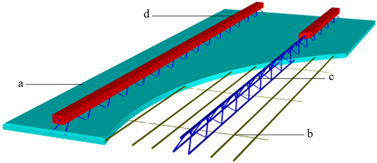
Figure 1: Schematic diagram of the construction of the prefabricated ribbed base slab. (a) Concrete base slab; (b) Structural rebar; (c) Truss rebar; (d) Concrete ribs
The experiment was conducted using the thickness of the base slab, truss spacing, and presence or absence of concrete ribs as design variables. Two precast reinforced truss concrete composite base slab specimens (YZB1 and YZB2) and one precast ribbed reinforced truss concrete composite base slab specimen (DLB1) were fabricated. The specimen dimensions were 3000 mm × 600 mm, which are commonly used in practice. The top chord reinforcement had a diameter of 10 mm, while the bottom chord reinforcement and the longitudinal reinforcement in the base slab had diameters of 8 mm. The truss web reinforcement and the transverse reinforcement in the base slab had diameters of 6 mm, with a transverse spacing of 600 mm. The top and bottom chord reinforcement, as well as the transverse and longitudinal reinforcement, in the base slab were all HRB400 hot-rolled ribbed bars, while the web reinforcement was HPB300 hot-rolled plain bar. The concrete strength grade for all specimens was C30. The main parameters of each specimen are presented in Table 1, and the schematic diagram of the reinforcement layout is shown in Fig. 2.
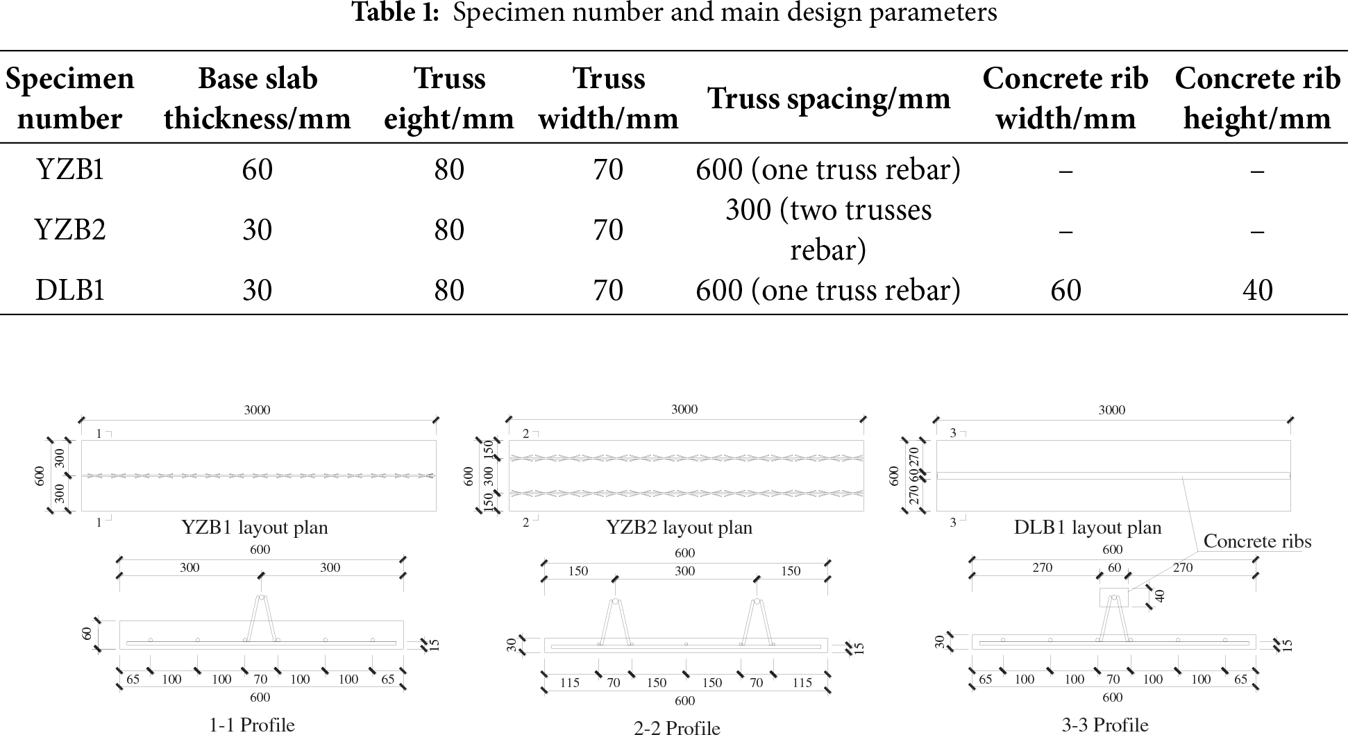
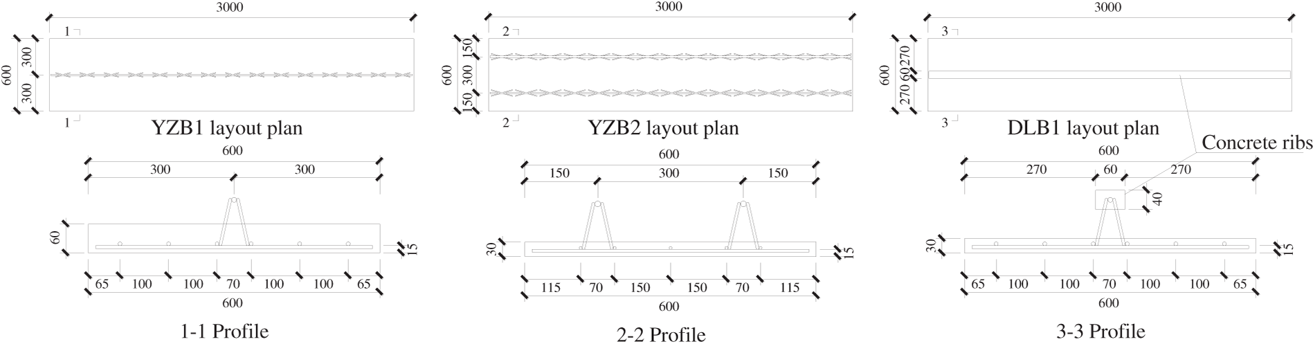
Figure 2: Diagram of specimen reinforcement (Unit: mm)
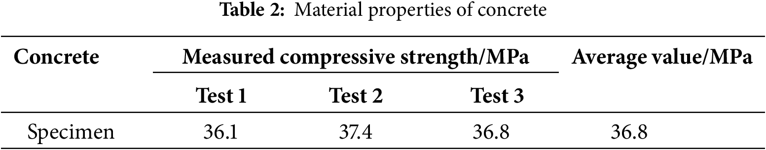
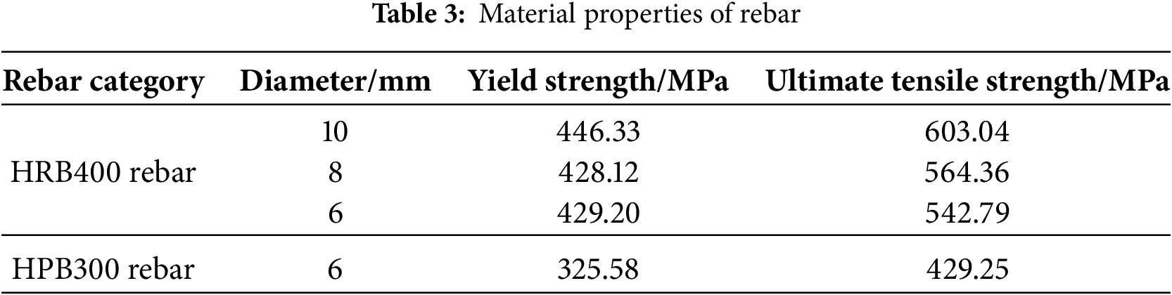
The composite base slab for the experiment was formed in a single pour of fine aggregate concrete. After curing was completed, three standard cubic specimens were cast during the pouring process to measure their compressive strength. Three reinforcement samples of different diameters were selected to test the mechanical properties of the reinforcement used in the specimens. Table 2 lists the compressive strength of the concrete cube specimens, and Table 3 lists the mechanical properties of the reinforcement, all of which were obtained from tests.
2.4 Measurement Content and Loading Scheme
According to scholars’ research [13,28], the experiment was carried out using a heavy load stack to achieve a homogeneous loading process on the specimen. The experiment was loaded incrementally until the specimen was damaged, and a single concrete block with a mass of about 25 kg was chosen for the stacking weight. Considering that the upper surface of the base slab specimen has exposed steel trusses and concrete ribs, making direct loading inconvenient, wooden blocks and boards were used to adjust the height, as shown in Figs. 3 and 4. When the following signs appear, the specimen is considered to have reached its maximum load capacity, and loading should be terminated: 1) the width of the cracks in the bottom slab reached 1.5 mm; 2) the maximum deflection reached 1/50 of the support span; 3) the concrete in the pressure zone was crushed during loading; 4) the rebar in the top chord of the steel truss was bent. The experimental site is shown in Fig. 5.
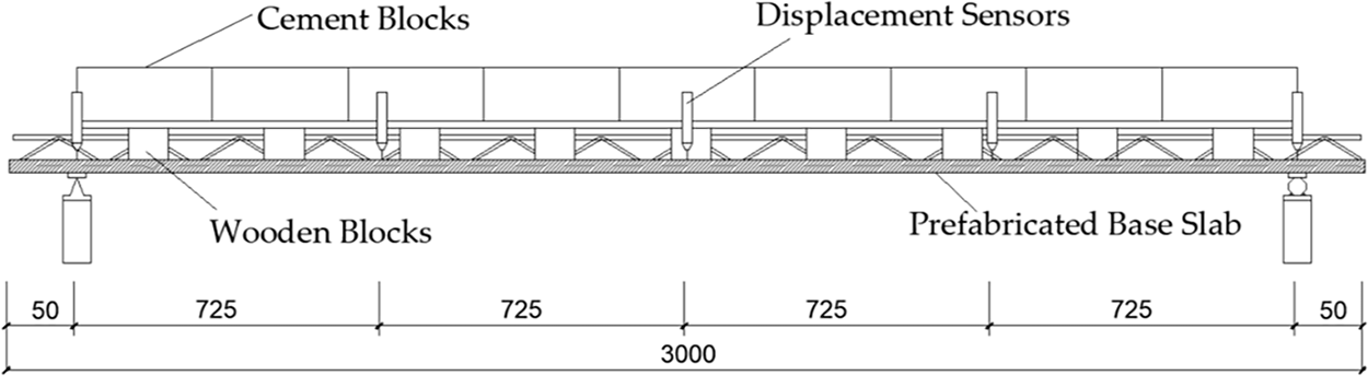
Figure 3: Schematic diagram of specimen loading arrangement (Unit: mm)
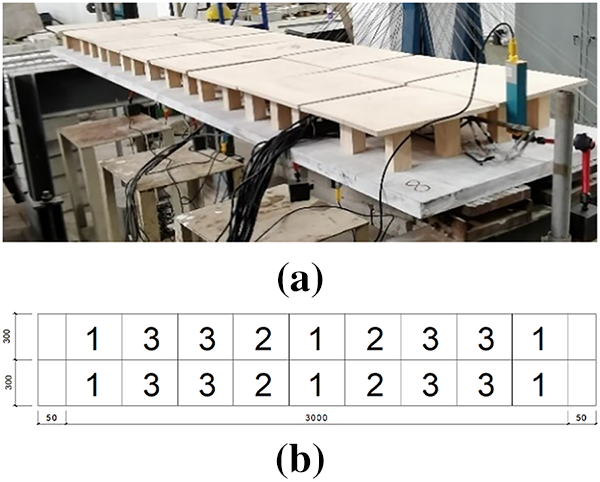
Figure 4: Experimental procedures (Unit: mm). (a) The wooden board is placed on the top layer of the test slab; (b) Schematic diagram of the test loading sequence
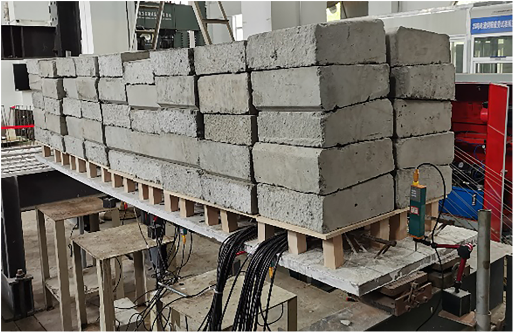
Figure 5: Experimental site loading diagram
This experiment monitored the specimens’ deflection changes, crack development, and load-carrying capacity. The number of displacement sensors was five and were placed at the two end supports, at 1/4, 1/2, and 3/4 spans of the test slab, as shown in Fig. 3 below.
3 Experimental Results and Analysis
In the initial stage of the experiment loading, the deformation characteristics of the three specimens were consistent. With the gradual increase of external loading, the concrete of the bottom slab developed cracks, and the damage process and bearing capacity performance of different specimens exhibited distinct behaviors.
Specimen YZB1 (one reinforcement truss, base slab thickness of 60 mm) was observed with the first crack at the bottom of the slab when the external load was increased to 2.5 kN/m2, near the center of the span, extending from the center of the slab width to a height of 40 mm at the side of the slab, with a crack width of 0.1 mm. When the load continued to be applied, no new cracks appeared in the base slab, but the existing cracks kept widening and propagating through the slab surface. When the load was increased to 3.89 kN/m2, the specimen suddenly sank, and part of the weld joint between the top chord reinforcement and web reinforcement of the truss broke and buckled (Fig. 6a), and the experiment was stopped. The distribution of cracks at the bottom of specimen YZB1 is shown in Fig. 7a.
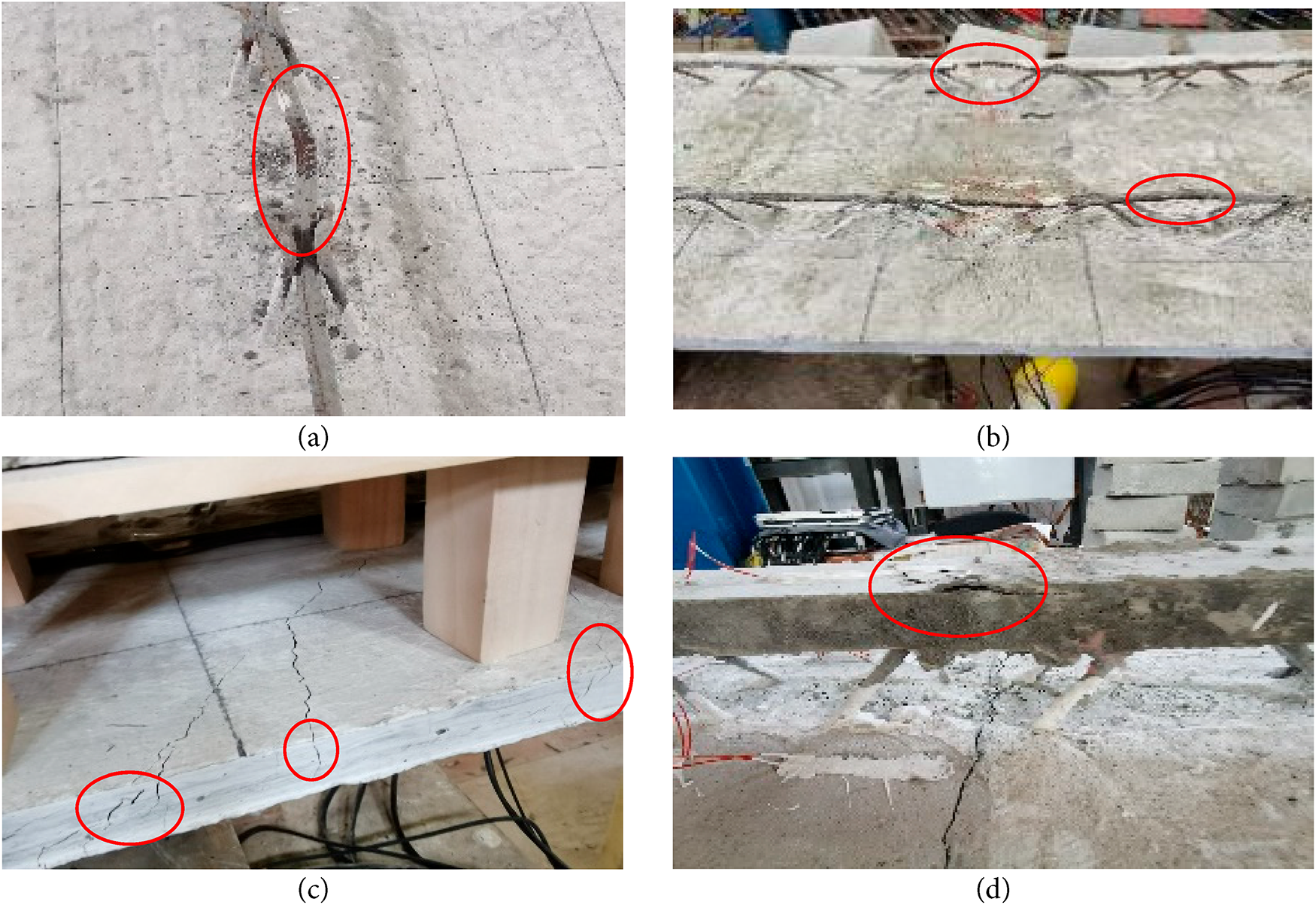
Figure 6: Specimen damage pattern. (a) Specimen YZB1 upper chord rebar is un-welded and flexed; (b) Specimen YZB2 upper chord rebars are compressed and flexed; (c) The crack in the span of specimen DLB1 develops upward along the side of the slab; (d) The concrete rib of specimen DLB1 was crushed
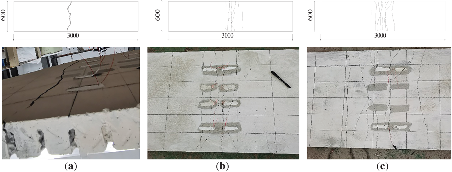
Figure 7: Distribution map of bottom crack morphology for three specimens (Unit: mm). (a) YZB1; (b) YZB2; (c) DLB1
The first crack in specimen YZB2 (two reinforcement trusses, base slab thickness of 30 mm) was observed near the span of the bottom of the slab when the load was increased to 5 kN/m2, extending from the center of the bottom of the slab to the edges on both sides, with a crack width of 0.05 mm. Continue loading, the number of cracks within the span increased, and they developed in an interlacing pattern from the bottom of the base slab to the side of the base slab. The crack width and length increased. When the external load increased to 8.47 kN/m2, the top chord reinforcement of the truss buckled (Fig. 6b), and the test was terminated. The distribution of cracks at the bottom of specimen YZB2 is shown in Fig. 7b.
The first crack in the ribbed composite slab base slab specimen DLB1 (one reinforcement truss, base slab thickness of 30 mm) was observed at the bottom of the slab at mid-span and along the slab width when the external load was increased to 6.39 kN/m2, with a crack width of 0.1 mm. With continued loading, new cracks appeared in the span, and the existing cracks widened and ran up the side of the slab through the surface (Fig. 6c). When the load was applied to 12.92 kN/m2, the upper concrete ribs were crushed (Fig. 6d), and the experiment was terminated. The distribution of cracks at the bottom of specimen DLB1 is shown in Fig. 7c.
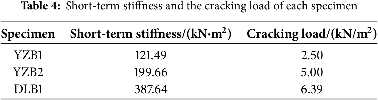
The load-deflection curve shown in Fig. 8 reflects the mid-span displacement changes of each specimen as the load increases, along with their respective variation values. Table 4 lists the calculated short-term stiffness and cracking load for three specimens. Short-term stiffness means the bending stiffness of the base slab during the construction of cast-in-place concrete for composite slabs, while the cracking load is defined as the load value at which the first crack is observed in the base slab during experimental loading. As shown in the figure, the bearing capacity performance and span deflection development trend of the three specimens are not the same. Loading commenced, revealing markedly different initial stiffnesses among the three specimens: DLB1 exhibited the highest stiffness, followed by YZB2 and YZB1. As the load continued, cracks appeared in the concrete at the bottom of the specimen base slabs. The contribution from the concrete in the bottom slab’s tension zone gradually diminished, causing a sudden drop in the section’s bending stiffness. The slope of the curve becomes smaller, and the inflection point appears after the cracking of the typical single-truss 60 mm thick base slab YZB1 and the ribbed concrete base slab DLB1.
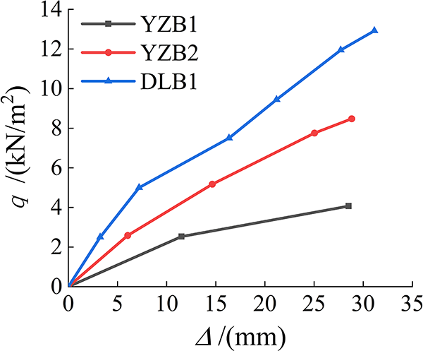
Figure 8: Mid-span load-deflection curve of the specimen
In contrast, the double truss base slab YZB2 shows a steady increase in load and deflection. The increase in load and deflection is uniform. Specimen YZB1 developed cracks in the base slab, the concrete lost its contribution to the work, and the reinforcement was subjected to the upper stacked load. Finally, the reinforcement was bent and damaged, resulting in poor ductility. Before cracking, specimen DLB1, the role played by the concrete rib is minimal, and at this stage, the base slab primarily bears the compressive stress. When the base slab is subjected to tension and cracks, the slope of the curve becomes smaller, with the neutral axis moving upward. The load from the base slab is transferred to the ribs via the diagonal rebars of the truss. At this point, both the ribs and the base slab bear the load simultaneously. This results in an increased slope on the curve, though it remains smaller than the initial slope.
From Table 4, the cracking load of both specimen YZB2 and specimen DLB1 is greater than the design load (4.56 kN/m2), which meets the construction requirements. By comparison, the short-term stiffness of specimen YZB2 is 1.64 times the short-term stiffness of specimen YZB1. Its cracking load is twice that of YZB1. So the loss of stiffness due to reduced slab thickness can be compensated by decreasing the truss spacing (increasing the number of truss groups), while also enhancing the ductility of the base slab. The short-term stiffness of specimen DLB1 is 1.94 times that of specimen YZB2 and 3.19 times the short-term stiffness of YZB1, and its cracking load is 1.28 times that of the cracking load of YZB2 and 2.56 times that of the cracking load of YZB1. This is due to the setting of concrete ribs, which increases the concrete area in the compression zone of the base slab. This enhances stiffness and load-bearing capacity, effectively addressing the issue of excessive deflection in precast slabs during construction. The concrete ribs form a whole with the base slab through the reinforcement truss, and the joint force effect is remarkable.
3.3 Theoretical Analysis and Calculation
According to the above experimental study, it can be seen that the ribbed base slab demonstrates optimal force performance, with the cracking load being higher than the design load, thus meeting the construction requirements. The additional concrete ribs effectively improve the flexural stiffness of the precast base slab. Considering the differences between a ribbed base slab and an ordinary precast base slab, combined with the experimental results in the paper and with reference to the design method of ordinary concrete members [29], the following three assumptions are made when carrying out the calculation of the positive section bearing capacity: (1) the section strain conforms to the flat section assumption; (2) the contribution of the tensile concrete to the section stiffness is considered before the base slab cracks; (3) the web reinforcement only plays the role of transferring force, and its contribution to the section stiffness is ignored.
Cracking Bending Moment
The experimental results show that the ultra-thin ribbed base slab (DLB1) is superior to the ordinary single truss base slab (YZB1) and the ultra-thin double truss base slab (YZB2). Additionally, the beneficial effect of ribbed concrete on a precast base slab can be supplemented by the calculation of the cracking moment, which is calculated separately for three base slab specimens (taking the mid-span moment) for comparison below. Referring to the relevant provisions in the Code for the Design of Concrete Structures (GB 50010-2010) [29], the cracking moment of reinforced concrete flexural members was calculated by Eqs. (1) and (2).
In the above equation,
The reinforcement in the specimen is converted into the equivalent cross-sectional area
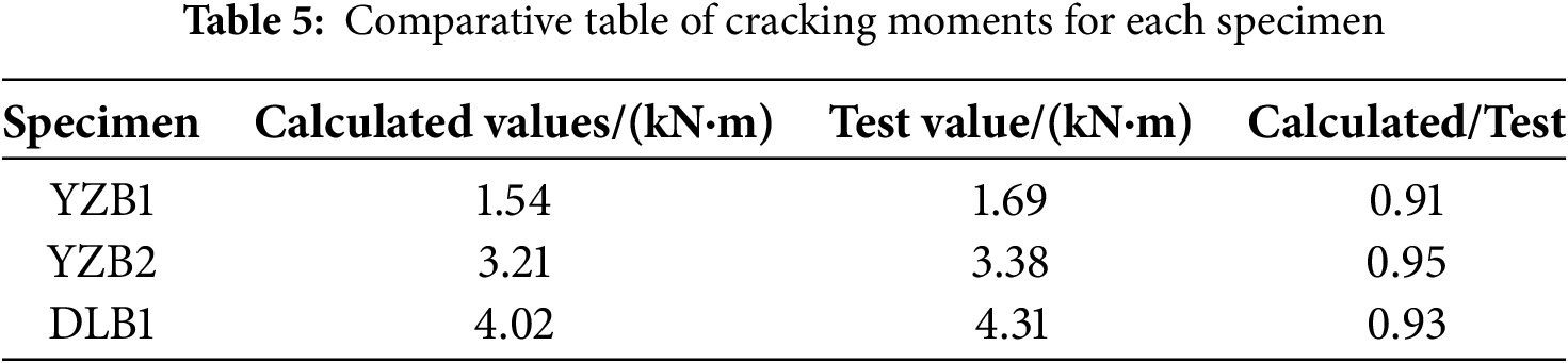
The calculated cracking moments were compared with those obtained from the experiments, and the results are listed in Table 5. The reason why the experimental value is larger than the calculated value is that the first crack observed in the experiment does not appear during the loading holding phase but during the application of the load, so the actual time when the crack is observed lags behind the cracking time of the base slab, making the recorded load slightly higher. As can be seen from the table, the calculated values are closer to the experimental values and do not affect the analysis of the results. It is obvious that the cracking moment of the ribbed base slab specimen DLB1 is substantially higher compared to that of the ordinary precast base slab specimen YZB1.
4 Numerical Simulation Analysis
Using ABAQUS numerical analysis software, this program investigates the effects of concrete rib dimensions and top chord reinforcement diameter on the short-term stiffness of the ribbed base slab during the construction phase.
Establish a numerical analysis model for the parameters of experimental specimen DLB1. The model of the ribbed base slab established in the ABAQUS software is shown in Fig. 9. The numerical analysis primarily references the relevant recommendations in GB 50010-2010 [29], and related research works [30,31]. For the model of concrete, the concrete damaged plasticity (CDP) model C3D8R solid element is selected (see Fig. 10). For reinforced structures, the double-line model T3D2 truss element is used. The concrete and the rebar have a strong bonding force, so the structural rebar of the base slab and the lower chord rebar of the steel truss are embedded in the concrete base slab using “Embedded” restraint, and the upper chord reinforcement is also embedded in the concrete ribs using “Embedded” restraint. Within the model, it is assumed that no slip deformation occurs between the rebars and the concrete. In order to avoid stress concentration, RP reference points are used at both ends of the original precast base slab to make coupling contact with the support positions. The boundary conditions are set at the RP points, simply supported by constraints. The model is calculated using a “Standard” solver, and the model load-deflection curve is extracted and compared with the experimental data, as shown in Fig. 11.
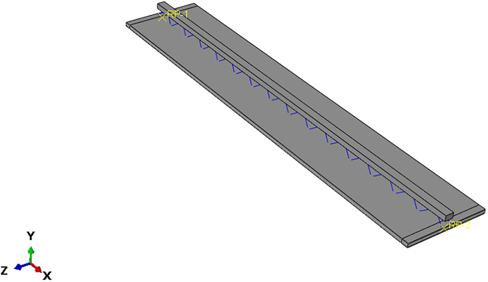
Figure 9: Schematic diagram of finite element numerical simulation model
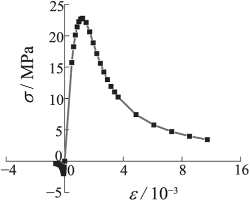
Figure 10: Concrete stress-strain relationship curve
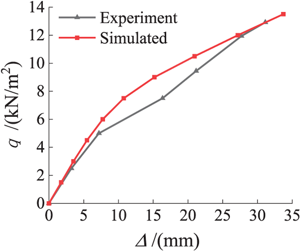
Figure 11: Comparison of experimental load-deflection curves with finite element simulation
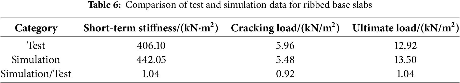
It can be seen from Fig. 11 that the curve fits more closely in the early stage, the deformation trend is the same, the initial stiffness is similar, the later damage phase also aligns well, and there is a significant difference in the elastic-plastic deformation in the middle. This is due to the ABAQUS simulation, in which the uniform load is applied continuously and uninterrupted, without a holding phase. Therefore, the deformation performance is more continuous, while the test loading process involves holding the load for observation. Consequently, the experimental value curve is a stepped change. The difference between the principal structural relationship and the interaction between concrete and reinforcement, compared with the actual one, is one of the reasons for the error. However, the short-term stiffness of the ribbed base slab under the construction load (4.56 kN/m2) differed by less than 10% when comparing the short-term stiffness, cracking load, and ultimate load of the software simulation and test, as shown in Table 6. The data obtained from numerical analysis are used to perform parameter analysis on the base slab.
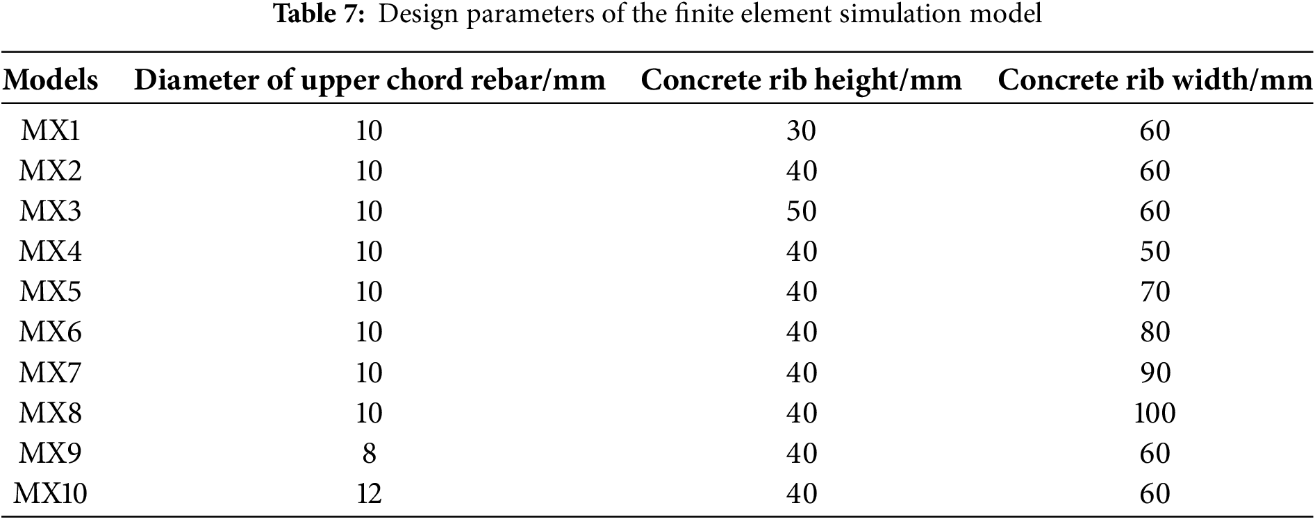
Based on the verification of the model accuracy, ten models were created to investigate the effects of three parameters: the top chord reinforcement diameter, concrete rib height, and rib width of the truss, on the short-term stiffness of the base slab. The detailed parameters of the models are shown in Table 7.
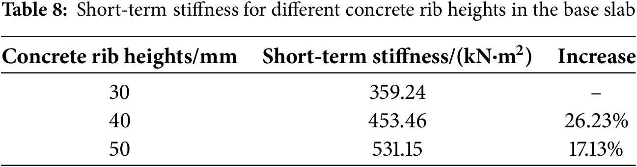
Considering that the truss height is 80 mm, the upper surface of the precast base slab requires piping during the construction stage. The total thickness of the composite control slab is less than 130 mm, and three different concrete rib heights of 30, 40, and 50 mm were designed to study their effects on the short-term stiffness of the base slab. The mid-span load-deflection curves are plotted in Fig. 12, and the corresponding short-term stiffness comparisons are listed in Table 8. The short-term stiffness of the ribbed base slab is positively correlated with the rib height, and for every 10 mm increase in rib height, the short-term stiffness increases by 21.68% on average. When the base slab cracks into the plastic stage, the load is transferred from the web reinforcement to the concrete rib, and the higher the rib height, the larger the compressed area and the better the performance.
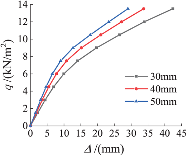
Figure 12: Load-deflection curves for different concrete rib heights in the base slab
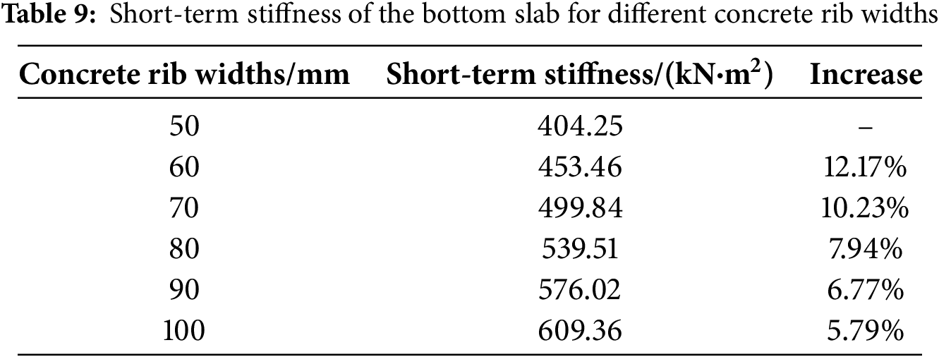
The load-deflection curves for different rib widths are plotted in Fig. 13, and the corresponding short-term stiffness comparisons are listed in Table 9. It can be seen from the chart that the short-term stiffness of the base slab gradually increases with the increase of concrete rib width, and the short-term stiffness of the base slab with 100 mm rib width is 1.5 times greater than that of the base slab with 50 mm rib width, and the short-term stiffness increases 8.58% on average for every 10 mm increase in rib width. The percentage increase in short-term stiffness decreases as the rib width increases, which is because the concrete ribs are connected to the precast base slab by rebar trusses. The rebar within the concrete rib has a limited range of restraint on the rib, thus limiting the effect on the short-term stiffness increase.
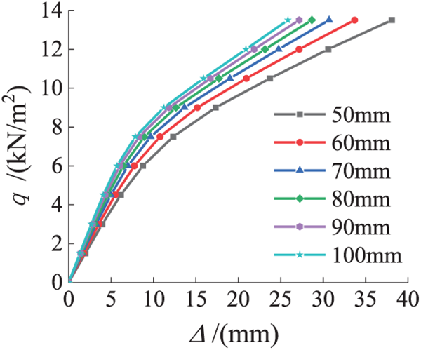
Figure 13: Load-deflection curves for different concrete rib widths in the base slab
4.2.3 Diameter of Truss Upper Chord Tendons
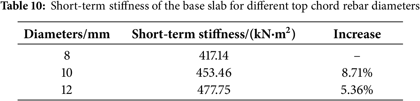
The typical top chord bars of 8, 10, and 12 mm diameters were selected for comparative analysis, and the mid-span load-deflection curves of each base slab are plotted in Fig. 14. The corresponding short-term stiffness comparisons are listed in Table 10. The short-term stiffness of the base slab increases slightly with the increase in the truss upper chord rebar diameter. The average short-term stiffness increases by 7.04% for each 2 mm increase in the diameter of the top chord. Although the increase in steel consumption improves the short-term stiffness of the base slab, the improvement is insignificant and increases the project cost. In practical engineering applications, increasing the short-term stiffness by increasing the rib height and width of concrete offers better mechanical performance and economic benefits than increasing the diameter of the top chord reinforcement. The increase in rib height will lead to the distance between the upper chord of the truss and the upper surface of the base slab becoming smaller, which is not conducive to the laying of pipelines, so the method of increasing the rib width to improve the short-term stiffness is clearly the best.
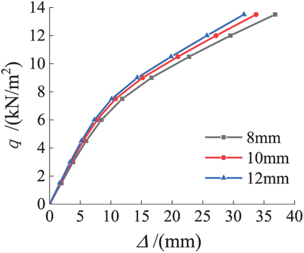
Figure 14: Load-deflection curves for different top chord rebar diameters in the base slab
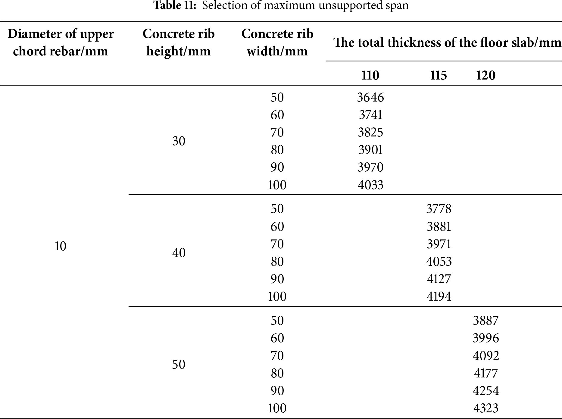
5 Maximum Support-Free Span Calculation
The ribbed base slab significantly improves the flexural stiffness of the base slab by setting the upper concrete ribs, which can eliminate bracing within a specific span, thus improving the construction efficiency and reducing the project cost. The deflection limits the span of free support. The calculated deflection value y needs to meet the deflection limit requirement in the construction stage, i.e.,
Static loading experiments on prefabricated ribbed base slabs and parametric analysis based on numerical simulations led to the following conclusions.
(1) Reducing the slab thickness of conventional single-truss composite slab specimens can compensate for the resulting loss in stiffness by incorporating double trusses or concrete ribs, while simultaneously enhancing the specimen’s cracking load capacity and deformation performance.
(2) Parametric analysis using finite element software reveals that increasing the height and width of concrete ribs, as well as enlarging the diameter of upper chord reinforcements, all enhance the short-term stiffness of ribbed base slabs. In engineering applications, widening concrete ribs is the most effective method for improving short-term stiffness.
(3) The cracking load of ribbed base slab specimens exceeds that of conventional base slabs, meeting the requirement for crack-free construction. This enables support-free construction within permissible spans.
Acknowledgement: Not applicable.
Funding Statement: This research was supported by the Guangxi Key Research and Development Program (Guike AB22036001, Guike AB21220046) and the Guangxi Young and Middle-aged University Teachers’ Scientific Research Fundamental Capability Enhancement Project (2024KY0717).
Author Contributions: The authors confirm contribution to the paper as follows: methodology and investigation, Yiyan Chen and Xiaogang Ye; software, Yiyan Chen and Jindan Zhang; validation and writing—review and editing, Yiyan Chen, Yihu Chen, and Min Zhang; funding acquisition, Yihu Chen and Yiyan Chen. All authors reviewed the results and approved the final version of the manuscript.
Availability of Data and Materials: The data that support the findings of this study are available from the corresponding author, Yihu Chen, upon reasonable request.
Ethics Approval: Not applicable.
Conflicts of Interest: The authors declare no conflicts of interest to report regarding the present study.
References
1. Costa S, Carvalho MS, Pimentel C, Duarte C. A systematic literature review and conceptual framework of construction industrialization. J Constr Eng Manage. 2023;149(2):03122013. doi:10.1061/(asce)co.1943-7862.0002410. [Google Scholar] [CrossRef]
2. Wasim M, Abadel A, Abu Bakar BH, Alshaikh IMH. Future directions for the application of zero carbon concrete in civil engineering—a review. Case Stud Constr Mater. 2022;17:e01318. doi:10.1016/j.cscm.2022.e01318. [Google Scholar] [CrossRef]
3. Wang X, Yang Q, Peng X, Xia K, Xu B. A review of mechanical performance studies on composite concrete beams and slabs. Materials. 2025;18(14):3259. doi:10.3390/ma18143259. [Google Scholar] [PubMed] [CrossRef]
4. Yang X, Wang Y, Liu Y, Wei Z. Experimental study and numerical simulation on mechanical properties of the bottom plate in the assembled composite slab with additional steel trusses. Adv Civ Eng. 2021;2021(1):7240994. doi:10.1155/2021/7240994. [Google Scholar] [CrossRef]
5. Qi J, Yang HC. Improving precast truss reinforced laminated concrete slab system. In: Proceedings of the 2020 IEEE 2nd International Conference on Architecture, Construction, Environment and Hydraulics (ICACEH); 2020 Dec 25–27; Hsinchu, Taiwan. doi:10.1109/icaceh51803.2020.9366259. [Google Scholar] [CrossRef]
6. Dong J, Fang G. Research on the mechanical performance of reinforced steel truss composite slabs enhanced with green steel fiber. Struct Concr. 2025;26(5):6294–312. doi:10.1002/suco.70246. [Google Scholar] [CrossRef]
7. Pang R, Xu Z, Liang S, Zhu X, Hu K. Experimental and analytical investigation on the in-plane mechanical property of discretely connected precast RC floor diaphragm. J Build Eng. 2020;32:101819. doi:10.1016/j.jobe.2020.101819. [Google Scholar] [CrossRef]
8. Lu L, Wang W, Zhang L, Shao Y. Longitudinal shear strength of recycled aggregate concrete prefabricated superimposed slabs. Eng Struct. 2023;281:115745. doi:10.1016/j.engstruct.2023.115745. [Google Scholar] [CrossRef]
9. Chen Y, Chen Y, Lu D, Zhang M, Lu P, Chen J. Experimental and numerical study of flexural stiffness performance of ultra-thin, prefabricated, and laminated slab base slabs. Sustainability. 2022;14(20):13472. doi:10.3390/su142013472. [Google Scholar] [CrossRef]
10. Chen Y, Shi HR, Zhu H, Wang CL, Zeng B. Flexural mechanism and design method for precast concrete splice slabs with welded junction plates. Struct Concr. 2024;25(6):4480–97. doi:10.1002/suco.202400154. [Google Scholar] [CrossRef]
11. Nie JG, Jiang YX, Nie X, Zhuang LD. Effect of truss reinforcement on mechanical properties of prefabricated slabs. J Build Struct. 2021;42(1):151–8. (In Chinese). doi:10.14006/j.jzjgxb.2020.0007. [Google Scholar] [CrossRef]
12. He Q, Wu Y, Hu C, Yang K, Yi W. Experimental study of the two-way mechanical behavior of tightly spliced prestressed reinforced concrete laminated slab. J Struct Eng. 2025;151(6):04025063. doi:10.1061/jsendh.steng-13472. [Google Scholar] [CrossRef]
13. Zhang J, Yao Y, Zhou X, Yang Y, Wang Y. Failure mode and ultimate bearing capacity of precast ribbed panels used for concrete composite slabs. Adv Struct Eng. 2013;16(12):2005–17. doi:10.1260/1369-4332.16.12.2005. [Google Scholar] [CrossRef]
14. Park MK, Lee D, Yang Y, Zhang D, Kim KS. Composite performance of prestressed hollow-core slabs with cast-in-place topping concrete. ACI Struct J. 2022;119(3):153–64. doi:10.14359/51734347. [Google Scholar] [CrossRef]
15. Jin J, Hu W, Zheng F, Wu B. Experimental and numerical studies on the mechanical behavior of a novel bidirectional, prestressed, prefabricated, composite hollow-core slab. Buildings. 2025;15(2):232. doi:10.3390/buildings15020232. [Google Scholar] [CrossRef]
16. Bian G, Jin H, Li J, Shi S, Lu X. Static bending mechanical properties of prestressed concrete composite slab with removable rectangular steel-tube lattice girders. Buildings. 2024;14(5):1187. doi:10.3390/buildings14051187. [Google Scholar] [CrossRef]
17. Song B, Song S, Liao Z, Wang CL. Experimental study on the in-plane shear performance of precast concrete slabs with wide and narrow joints. Structures. 2025;75:108680. doi:10.1016/j.istruc.2025.108680. [Google Scholar] [CrossRef]
18. Dinh PT, Doh JH. Experimental study and numerical modelling of post-tensioning systems on the transverse direction of composite steel deck-concrete structures. Structures. 2024;70(1):107881. doi:10.1016/j.istruc.2024.107881. [Google Scholar] [CrossRef]
19. Zheng W, Lu X, Wang Y. Flexural behaviour of concrete composite slabs with precast ribbed reactive powder concrete bottom panels. J Comput Theor Nanosci. 2016;13(3):1831–9. doi:10.1166/jctn.2016.5120. [Google Scholar] [CrossRef]
20. Luo B, Tang Z, Du T, Song Y, Cao G. Experimental study on flexural performance of composite slab with UHPC layer. Constr Build Mater. 2025;492:143023. doi:10.1016/j.conbuildmat.2025.143023. [Google Scholar] [CrossRef]
21. Liu J, Hu H, Li J, Chen YF, Zhang L. Flexural behavior of prestressed concrete composite slab with precast inverted T-shaped ribbed panels. Eng Struct. 2020;215:110687. doi:10.1016/j.engstruct.2020.110687. [Google Scholar] [CrossRef]
22. Huang H, Li J, Zeng C, Zhu M, Zhang M. Simplified elastic design method using equivalent span ratio for two-way concrete composite slabs with precast ribbed panels. Struct Concr. 2019;20(1):213–24. doi:10.1002/suco.201800097. [Google Scholar] [CrossRef]
23. Zhao P, Qin Y, Wu B, Chen Y, Chen X, Wen J. Impact of stiffener configuration on the structural performance of orthotropic steel bridge deck. Struct Durab Health Monit. 2025;19(5):1367–86. doi:10.32604/sdhm.2025.067558. [Google Scholar] [CrossRef]
24. Favarato LF, Gomes AVS, de Moura Candido DC, Ferrareto JA, da Cruz Vianna J, Calenzani AFG. On the composite behavior of a rebar truss ribbed slab with incorporated shuttering made of lipped channel section. J Build Eng. 2022;55:104663. doi:10.1016/j.jobe.2022.104663. [Google Scholar] [CrossRef]
25. Khandan R, Noroozi S, Sewell P, Vinney J. The development of laminated composite plate theories: a review. J Mater Sci. 2012;47(16):5901–10. doi:10.1007/s10853-012-6329-y. [Google Scholar] [CrossRef]
26. Zhang ZJ, Wang WW, Zhen JS, Li BC, Cai DC, Du YY, et al. Moment redistribution effect of the continuous glass fiber reinforced polymer-concrete composite slabs based on static loading experiment. Struct Durab Health Monit. 2025;19(1):105–23. doi:10.32604/sdhm.2024.052506. [Google Scholar] [CrossRef]
27. Xiao G, Chen X, Xu L, Kuang F, He S. Flexural performance of UHPC-reinforced concrete T-beams: experimental and numerical investigations. Struct Durab Health Monit. 2025;19(5):1167–81. doi:10.32604/sdhm.2025.064450. [Google Scholar] [CrossRef]
28. Zeng X, Feng Y, Ruan S, Xu M, Gong L. Experimental and numerical study on flexural behavior of a full-scale assembled integral two-way multi-ribbed composite floor system. Buildings. 2023;13(10):2517. doi:10.3390/buildings13102517. [Google Scholar] [CrossRef]
29. GB50010-2010. Code for design of concrete structures. Beijing, China: AQSIQ; 2010. (In Chinese). [Google Scholar]
30. Han LH, Yao GH, Tao Z. Performance of concrete-filled thin-walled steel tubes under pure torsion. Thin Walled Struct. 2007;45(1):24–36. doi:10.1016/j.tws.2007.01.008. [Google Scholar] [CrossRef]
31. Hassan MK, Subramanian KB, Saha S, Sheikh MN. Behaviour of prefabricated steel-concrete composite slabs with a novel interlocking system-Numerical analysis. Eng Struct. 2021;245:112905. doi:10.1016/j.engstruct.2021.112905. [Google Scholar] [CrossRef]
Cite This Article
 Copyright © 2026 The Author(s). Published by Tech Science Press.
This work is licensed under a Creative Commons Attribution 4.0 International License , which permits unrestricted use, distribution, and reproduction in any medium, provided the original work is properly cited.
 Downloads
 Citation Tools