
 Submit a Paper
 Open Access
ARTICLE
Research on Human-Vehicle-Road Friendliness Based on Improved SH-GH-ADD Control
School of Mechanical Engineering, Southwest Jiaotong University, Chengdu, 610031, China
* Corresponding Author: Weiping Ding. Email:
(This article belongs to the Special Issue: Passive and Active Noise Control for Vehicle)
Sound & Vibration 2023, 57, 45-68. https://doi.org/10.32604/sv.2023.043279
Received 27 June 2023; Accepted 08 September 2023; Issue published 10 November 2023
 View Full Text
 Download PDF
Abstract
The hub-driven virtual rail train is a novel urban transportation system that amalgamates the benefits of modern trams and buses. However, this system is plagued by issues such as decreased ride comfort and severe deformation of urban roads due to the increase in sprung mass and long-term rolling at the same position. To address these concerns and improve the human-vehicle-road friendliness of the virtual rail train, we propose an Improved Sky-Ground Hook and Acceleration-Driven Damper control (Improved SH-GH-ADD control) strategy for the semi-active suspension system. This control monitors the vibration acceleration signal of the unsprung mass in real-time and selects the mixed Sky-Hook and Acceleration-Driven Damper (SH-ADD) control or the mixed Ground-Hook and Acceleration-Driven Damper (GH-ADD) control based on the positive and negative values of the vibration acceleration of the unsprung mass. The Improved SH-GH-ADD control combines the advantages of SH-ADD control and GH-ADD control to achieve control of the sprung mass and unsprung mass in the full frequency band. Finally, through simulation and comparative analysis with traditional SH-ADD, GH-ADD, and mixed SH-GH control, we demonstrate the exceptional performance of the proposed algorithm.Keywords
The virtual rail train is a novel urban rail transit system that merges the characteristics of buses, trams, and light rail units to create a unique fusion of cars and trains, providing a solution to the road traffic pressure faced by small and medium-sized cities. In a study conducted on the virtual rail train in Zhuzhou, Hunan, and the intelligent rail in Yibin, Sichuan, it was observed that the running route of the train had caused severe permanent pavement deformation [1]. This deformation not only affects the quality and lifespan of the road but also leads to uneven pavement, ultimately impacting passenger comfort. Therefore, further research on human-vehicle-road friendliness of virtual rail trains is of great significance.
Considering the factors of energy consumption, control bandwidth, and system stability, semi-active suspension is considered to achieve the best results in terms of cost and performance. In the research of semi-active suspension control algorithm, the main focus is on controlling the vibration of the sprung mass or unsprung mass, with the aim of improving ride comfort and road friendliness. Some common methods include robust control [2], Hybrid Control Algorithm Sliding Mode-PID [3], synovial control based on reference model [4], and optimal control [5], Nguyen proposed a fuzzy sliding mode ratio integral control method based on FSMPIF tuning to reduce the spring mass displacement and acceleration [6], and an adaptive fuzzy sliding mode proportional-integral-derivative method based on fuzzy tuning to reduce the body displacement and vibration acceleration [7]. In view of the real-time, engineering practicality, and simplicity of the algorithm, Sky-Hook (SH) control was first proposed by Karnopp et al. [8]. Ground-Hook (GH) control was proposed by Valášek et al. [9], and Acceleration-Driven Damper (ADD) control was widely used by Savaresi et al. [10].
Switched Sky-Hook (SH) and Acceleration-Driven Damper (ADD) have their respective advantages and disadvantages in suppressing the vibration of the sprung mass. Specifically, SH has a significant vibration control effect on the sprung mass in the low-frequency band (close to the inherent frequency domain of the sprung mass), but its vibration control effect on the sprung mass is not evident in the high-frequency band (beyond the inherent frequency domain of the sprung mass). In contrast, ADD’s vibration control effect on the sprung mass is noticeable in the high-frequency band, but it is not evident in the low-frequency band (close to the inherent frequency domain of the sprung mass). Based on this situation, Savaresi et al. proposed a hybrid SH-ADD algorithm that combines the advantages of SH control and ADD control to achieve full-band suppression of sprung mass vibration, resulting in a good control effect [11]. Similarly, the switched Ground-Hook (GH) has a noticeable vibration control effect on the unsprung mass in the high-frequency band (exceeding the unsprung natural frequency domain), but its vibration control effect on the unsprung mass in the low-frequency band (close to the unsprung natural frequency domain) is not evident. Therefore, an ADD control strategy for unsprung mass control is proposed, combined with the reference ADD control. The characteristic of the ADD control is that the vibration control effect of the unsprung mass is noticeable in the low-frequency band (close to the unsprung natural frequency domain), while its vibration control effect is not evident in the high-frequency band (beyond the unsprung natural frequency domain). Based on this theory, the GH-ADD algorithm is proposed, which combines GH control and ADD control to achieve full-band suppression of unsprung mass vibration, resulting in a good control effect [12].
Due to the virtual rail train’s intelligent operation on the established ‘virtual track’ and repeated rolling of the road, the damage to the road is more severe. Currently, the control strategies for ride comfort and road friendliness of virtual rail trains are limited. In contrast, in the field of heavy vehicles, mixed SH-GH control strategies are widely employed [13]. The control strategy combines SH and GH control by adjusting the weight co-efficient. However, in practical engineering applications, the fixed value of the weight co-efficient cannot be adjusted in real-time according to the vehicle operating conditions, resulting in different control effects under varying operating conditions. Considering the advantages and disadvantages of SH control and GH control, namely, the superior control effect of SH control on the sprung mass in the low-frequency band and the superior control effect of GH control on the unsprung mass in the high-frequency band, the simple combination of SH control and GH control cannot achieve the vibration suppression effect of the entire frequency band of the vehicle.
Given the aforementioned reasons, this paper proposes an Improved SH-GH-ADD control method. The control method achieves full-band control of the sprung mass by monitoring the vibration acceleration signal of the unsprung mass in real-time and utilizing the SH-ADD control when the unsprung acceleration is positive. Conversely, the selection of GH-ADD control also controls the unsprung mass in the full frequency domain. The proposed control strategy combines the advantages of SH-ADD control and GH-ADD control, which effectively reduces the vibration acceleration and tire dynamic.
The main contribution of this paper is to propose a damping control method based on the vibration acceleration of unsprung mass, which is used to control the vibration of sprung mass and unsprung mass. At the same time, the friendliness between human-vehicle-road is evaluated by various evaluation indexes. In this study, the developed method achieves the control of the output damping force of the shock absorber by identifying specific parameters through the established multi-body vehicle dynamics. Then, a variety of evaluation indicators are used to compare and analyze various control strategies to evaluate the control effect of the model.
In order to conduct a comprehensive assessment of the impact of diverse control strategies on the overall performance of vehicles, it is imperative to take into account various factors such as human comfort, ride comfort, and road friendliness. Therefore, this research paper employs the environmental vibration dose value (eVDV) as a metric for evaluating human comfort. Moreover, the relationship between the weighted vibration level Law and weighted acceleration root mean square value and human subjective feeling is adopted as a measure of ride comfort. Furthermore, this paper introduces a predictive model of permanent deformation caused by repeated vehicle loads on roads as an evaluation index of road friendliness to determine the overall level of damage caused by vehicles to roads. Through the comprehensive analysis of the above evaluation indexes, the influence of various control strategies on the overall performance of the vehicle can be effectively evaluated.
2.1 Human Comfort Evaluation Index
The most important factor of environmental vibration on human health is the vibration frequency [14–17]. When the human body is affected by a certain frequency of environmental vibration, the degree of influence increases with the increase of vibration intensity. The natural frequency of the balance organ of the human body is in the range of 0.5∼1.3 Hz. For the low-frequency vibration of 0∼1 Hz, it can trigger the vestibular organ and central nervous system of the human body. The complex physiological and psycho-logical processes lead to the occurrence of motion sickness, which is manifested as the imbalance of the human body, vomiting, dizziness and other symptoms [18]. The frequency domain resonance range of the human body is 4∼12.5 Hz, of which 4∼8 Hz and 8∼12.5 Hz are the resonance regions of the human internal organs and spinal system, respectively [19]. Therefore, long-term exposure to the vibration environment of the car will affect human health.
The objective evaluation of environmental vibration is mainly based on the quartic vibration dose value (VDV) and the estimated vibration dose value (eVDV) [20]. Because VDV is an evaluation dose with long detection duration and complicated calculation, it is used to evaluate the effect of high peak coefficient (peak factor greater than 9) vibration caused by excessive pulse on the human body, while eVDV is for continuous vibration with amplitude not changing with time and peak factor between 3 and 6. The eVDV value is slightly smaller than the VDV value, but the difference is very small and can be ignored [21]. The calculation formula of the quartic vibration dose value (VDV) and the estimated vibration dose value eVDV [22] is:
where:
2.2 Vehicle Ride Comfort Evaluation Index
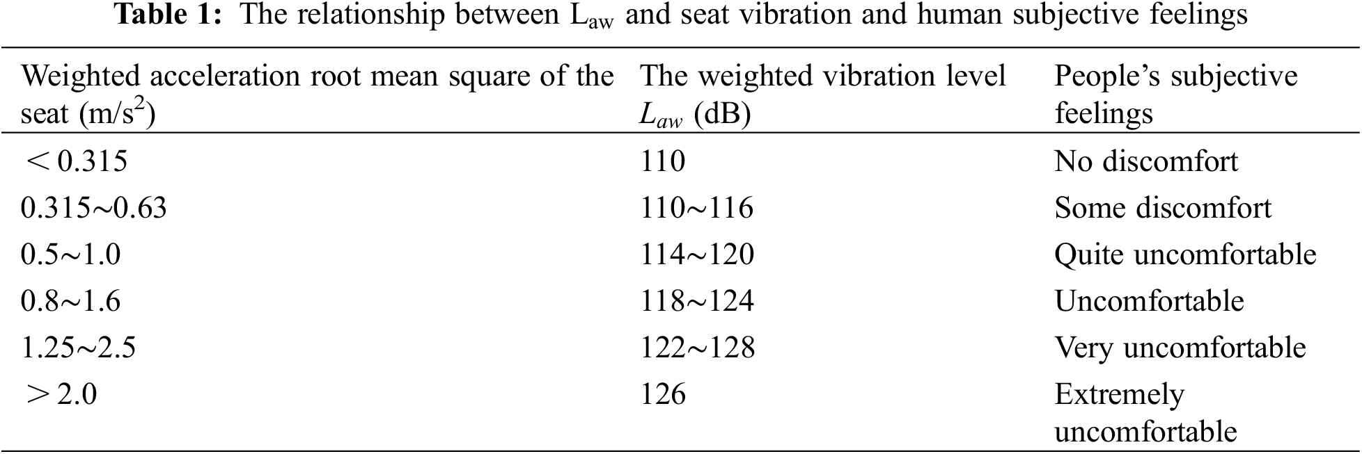
In order to better evaluate the ride comfort of the virtual track train of the new urban rail transit, this paper measures the vibration acceleration of the head car floor, and then converts it to the subjective feeling of passengers sitting on the seat according to the empirical formula, that is the vibration intensity at the floor is 1.4 times the vibration intensity on the seat [23], and the ride comfort of the virtual track train is evaluated by the weighted vibration level
where:
Table 1 shows the relationship between the weighted vibration level
2.3 Road-Friendliness Criteria
In order to predict the overall damage degree of the road under repeated vehicle load, the empirical relationship between the permanent deformation of the granular layer and the subgrade and the number of load times and the compressive stress level is established [24]:
where:
In order to calculate
where:
In this paper,
Since
where:
Therefore, the permanent deformation prediction model of the overall damage degree of the vehicle load repeated on the road is:
3 Vehicle System Dynamics Model
3.1 Dynamic Model of Hub-Driven Virtual Rail Train
The dynamic model of hub-driven virtual rail train is equivalent to a dynamic system with complete constraints. It is usually expressed by the differential-algebraic equations (DAEs) of index-3 [26], and its expression is:
where:
By solving the first and second derivatives of the constraint equation
As shown in Fig. 1, the 1/4 vehicle model of the virtual rail train adopts a double wishbone suspension, which is mainly connected by a spherical hinge joint, a cylindrical pair, a revolute pair and a universal joint, and has a certain dynamic performance through the damping force of the shock absorber, the stiffness of the spring and the bushing. The revolute joint limits its degree of freedom to 1 and can only rotate in one plane. For example, Fig. 2 is a planar double-link mechanism with two revolute joints. Assuming that the system is only affected by gravity, the gravitational acceleration is
where: generalized force vector
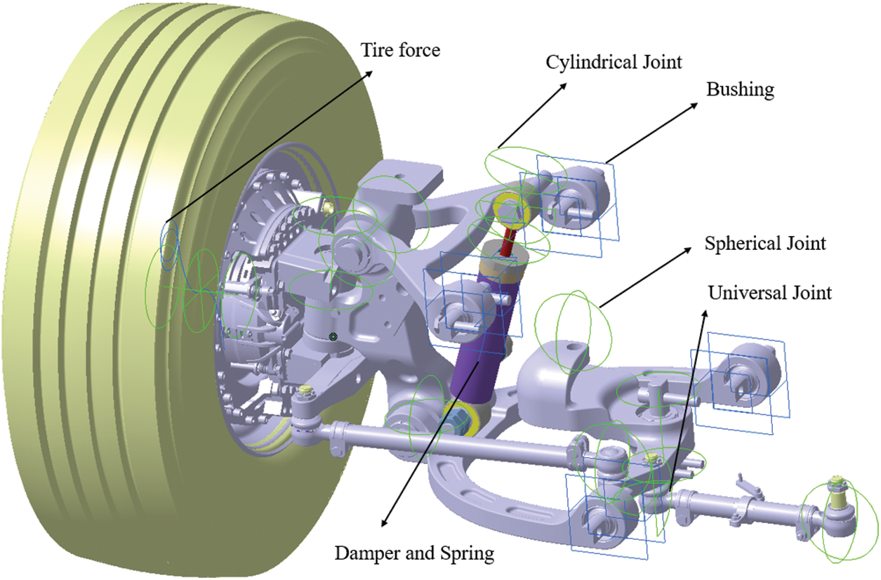
Figure 1: Virtual rail train 1/4 vehicle model
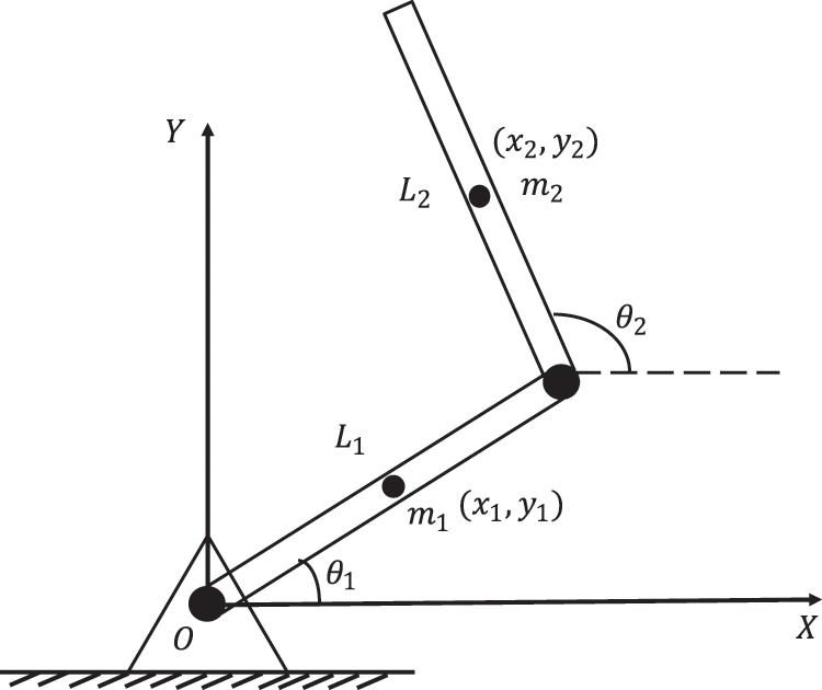
Figure 2: Planar double-link mechanism
The cylindrical pair limits its degree of freedom to 2, can rotate in a plane and can move in its axial direction. For example, Fig. 3 is a mechanism with a cylindrical pair. Assuming that the system is only affected by gravity, the gravity acceleration is
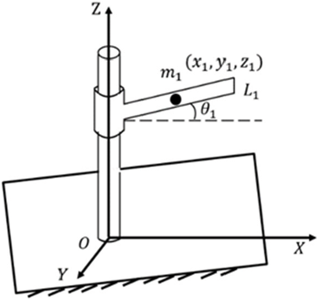
Figure 3: Mechanisms with cylindrical pairs
where: generalized force vector
The spherical hinge joint limits its degree of freedom to 3 and can rotate in three axial directions. For example, Fig. 4 is a mechanism with a spherical hinge joint, where H is the axis of the rod
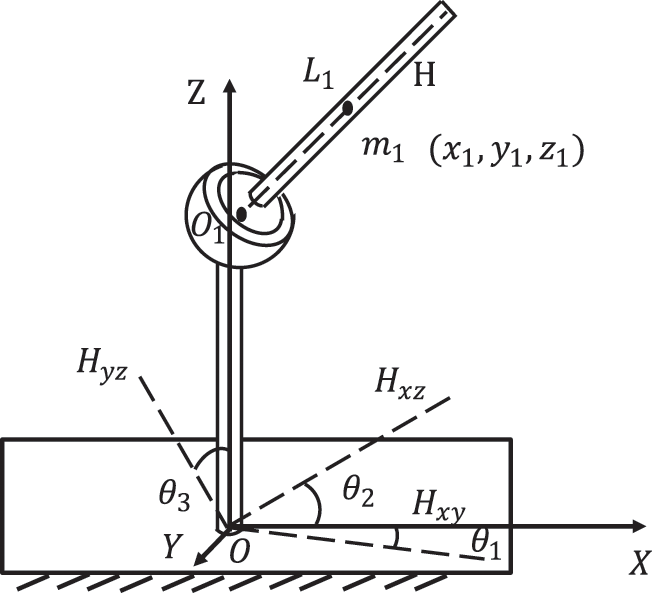
Figure 4: Mechanism with spherical hinge joint
The universal joint limits its degree of freedom to 2 and can rotate in two axial directions. For example, Fig. 5 is a mechanism with a universal joint, where H is the axis of the rod
where: generalized force vector
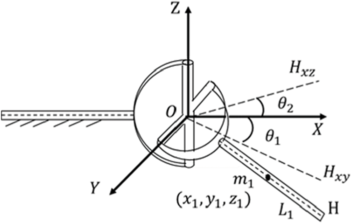
Figure 5: Mechanisms with universal joints
The Spring-Damping force system [28] is shown in Fig. 6, object I and object J are connected by Spring-Damper (SD), and the connection points are
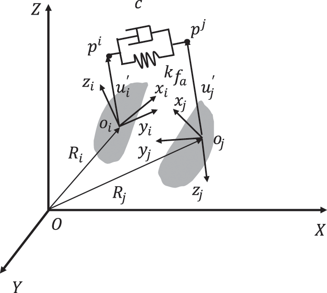
Figure 6: Spring-damping force system
The generalized speed is:
where:
The force of SD is always along the line of
where: k is the spring stiffness; c is the damping coefficient of the shock absorber; s is the deformation of the spring.
The array of the force acting on object I and object J in the global coordinate system is:
where:
The virtual work done by SD is:
where: E is expressed as a unit matrix of order 3;
Then the relationship between generalized force vectors
Bring Eqs. (21)∼(22) and (24)∼(25) into Eq. (23) and compare them with Eq. (26). The generalized force vectors acting on objects I and J are:
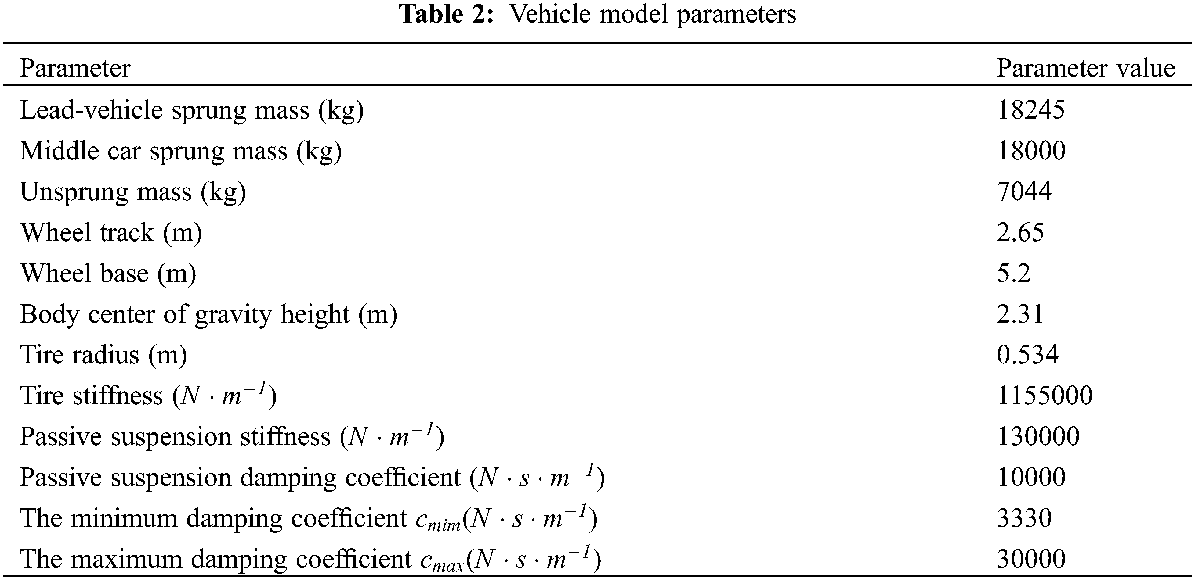
Based on the principle of DAEs, the mechanism of various kinematic pairs and elastic elements in the 1/4 vehicle dynamics model is analyzed. Because the semi-active control algorithm tends to 1/4 suspension model, it is easier to study and analyze the characteristics of the algorithm by using 1/4 suspension model, but it cannot fully reflect the complex environment and the nonlinear characteristics of the vehicle itself. Therefore, in order to improve the transmission efficiency between components, this paper establishes a hub-driven virtual rail train dynamics model based on a multi-body dynamics software, as shown in Fig. 7. As shown in Table 2, except that the ‘minimum/maximum damping coefficient‘ comes from experience, the remaining parameters are measured by the virtual rail train.
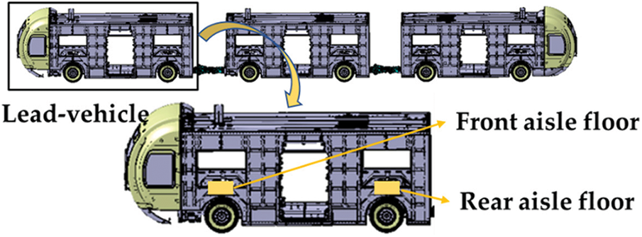
Figure 7: Dynamic model of hub-driven virtual rail train
3.2 Dynamic Model of Hub-Driven Virtual Rail Train
In order to verify the validity and correctness of the multi-body dynamics model, simulation and experiment are used to verify each other. Due to the limited conditions in the development and design stage, the test condition is that the vehicle is driven on the asphalt pavement (Grade B pavement) at a speed of 15 km/h under full load (as shown in Fig. 8). The vibration acceleration signals at the corresponding points of the front aisle floor and the rear aisle floor of the lead-vehicle are measured by the acceleration sensor, as shown in Figs. 7 and 9, and the respective acceleration frequency domain signals are obtained.
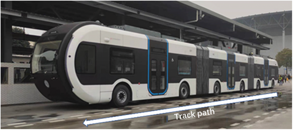
Figure 8: Vehicle track path
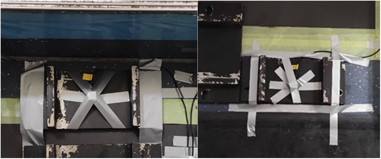
Figure 9: Acceleration sensor on floor of front aisle and rear aisle
As shown in Figs. 10 and 11, the vibration acceleration frequency domain signals at the corresponding points of the front aisle and the rear aisle of the lead-car are simulated and tested. Table 3 shows the comparison between the simulation results and the test results.
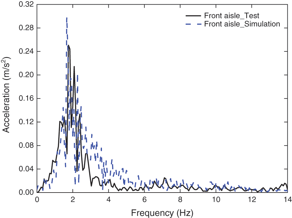
Figure 10: Frequency domain response at the front aisle floor of the lead-vehicle
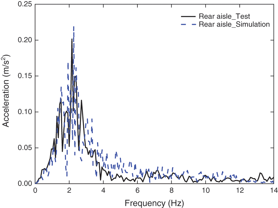
Figure 11: Frequency domain response at the rear aisle floor of the lead-vehicle
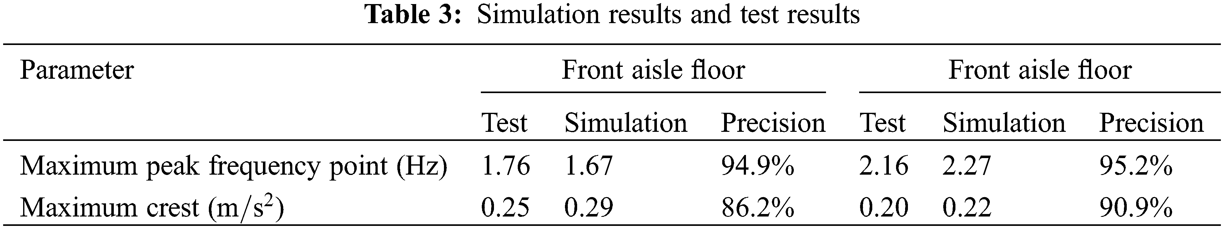
As shown in Table 3, the simulation results are basically consistent with the experimental results, but there are some differences. These differences are mainly due to the following reasons:
1. The B-level road surface used in the simulation is generated by simulating random road roughness, which is not obtained by real measurement, so there is a certain difference between the road surface and the actual test.
2. In the simulation process, the frame is only regarded as a rigid body without considering the flexible treatment. However, in practice, the large bus wheelbase is larger, resulting in lower frame stiffness.
3. There are also some differences between the tires used in the simulation and the actual tires.
In general, the accuracy of experimental data and simulation data is maintained above 86% from the perspective of peak value and peak frequency, which proves that the established dynamic model has high validity and correctness. However, it should be noted that the above differences may have an impact on the results.
4 Improved SH-GH-ADD Control Strategy
4.1 Passive Suspension 1/4 Model
The classical damping control is aimed at the single-freedom vibration system, which is more suitable for the vertical vibration control of the 1/4 vehicle model with two degrees of freedom. At present, the mainstream idea of vehicle damping control is to promote and apply the 1/4 damping suspension model from the physical point of view. Therefore, it is necessary to introduce and analyze the 1/4 suspension model. The 1/4 model of vehicle suspension system is shown in Fig. 12.
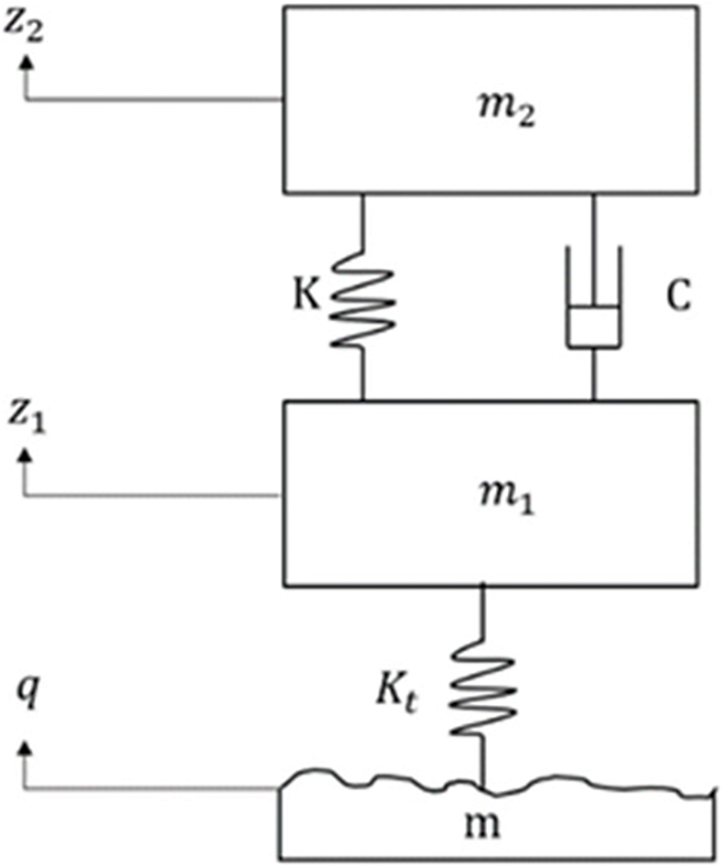
Figure 12: Suspension system 1/4 model
According to the Lagrange equation, the differential equation of motion of the 1/4 suspension system of the virtual track train is established:
where:
Classical damping control includes SH control, GH control and ADD control [29]. SH is assumed that there is a damper connected to the reference position (sky) and the vehicle body to suppress the body vibration caused by the road roughness excitation [30,31]. For the switch-type SH control, the control principle is:
where:
GH is assumed that there is a damper connected to the reference position (ground) and unsprung mass to suppress the unsprung mass vibration caused by road roughness excitation. For the switch-type GH control, the control principle is:
where:
In the traditional vehicle suspension control, ADD aims to suppress the body acceleration. For the switching ADD control, the control principle is:
where:
SH is widely used in automobile suspension. The goal is to suppress the body acceleration
SH control and GH control are complementary in the control effect of vertical vibration of vehicles. SH control is mainly the control of sprung mass vibration, while GH control is mainly the control of unsprung mass vibration. Mixed SH-GH control [32] connects SH control with GH control by adjusting the value of parameter u, and realizes the proportion of sprung and unsprung mass control by adjusting the value of u. The control principle of Mixed SH-GH control is shown in equation, where the value range of u is [0, 1]. When
where:
The control of the mixed SH-GH combines the advantages of the SH control and the GH control. However, because SH control has a better vibration suppression effect on the sprung mass near the natural frequency of the sprung mass, the GH control has a better vibration suppression effect on the unsprung mass above the natural frequency of the unsprung mass; Once the engineering application is carried out, the weight coefficient value will not change in real time with the vehicle operating conditions, so the control effect is different under different operating conditions; As shown in Eq. (35), in theory, the shock absorber cannot provide two damping coefficients at the same time, that is,
4.4 Improved SH-GH-ADD Control Strategy
At present, there are still some defects in the classical damping control and mixed SH-GH control in terms of human-vehicle-road friendliness, that is, it is impossible to reasonably select control strategies for the vibration frequency of human body and vehicle to improve human-vehicle-road friendliness. Therefore, two new control strategies, SH-ADD control and GH-ADD control are proposed. The control principles are as follows:
where:
In order to reasonably determine
As shown in Fig. 13, in the low frequency band, if the damping is increased, it is helpful to reduce the amplitude of the sprung mass, while in the middle and high frequency bands, the result is opposite. If the damping is increased, the amplitude of the sprung mass will increase. Among them,
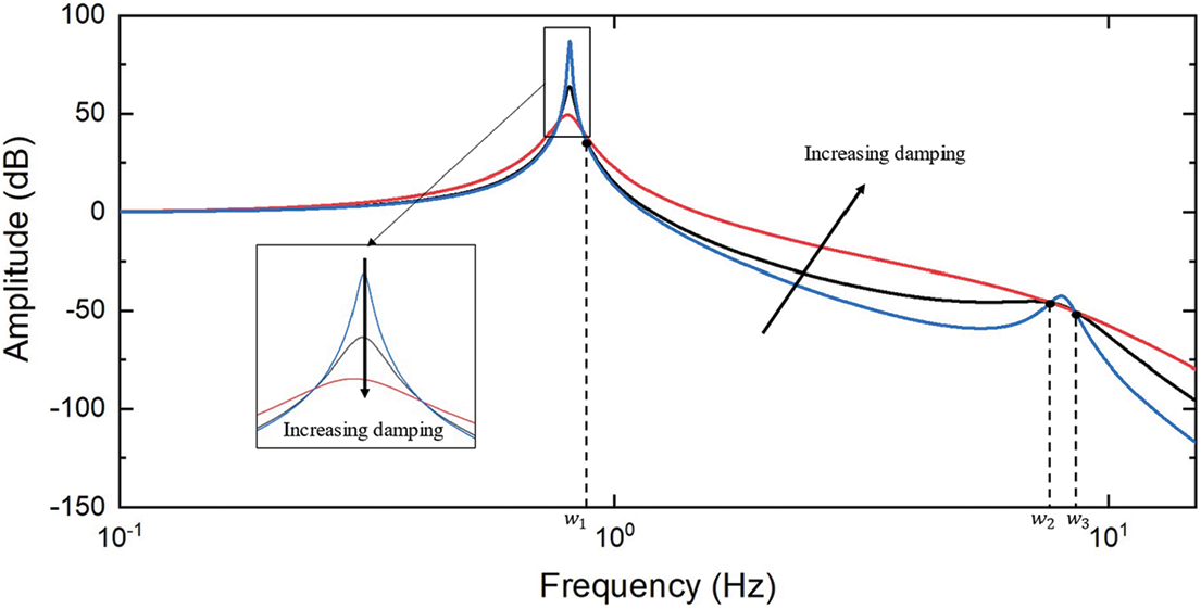
Figure 13: Amplitude-frequency characteristics of sprung mass
GH-ADD control is to realize the control of unsprung mass in the whole frequency band. Referring to ADD control, ADD control suitable for unsprung mass control is proposed, which combines the advantages of GH control. It is characterized by ADD control in low frequency (near the natural frequency domain of unsprung mass) and GH control in high frequency (above the natural frequency of unsprung mass). GH-ADD control can suppress the vibration of unsprung mass in the whole frequency band. The principle of GH-ADD control is as follows:
Aiming at the control of unsprung mass, an ADD control similar to Eq. (34) is proposed. The ADD control rules in GH-ADD control are as follows:
where:
In order to reasonably determine
As shown in Fig. 14, in the low frequency band, if the damping is increased, it is not conducive to reducing the amplitude of the unsprung mass, while in the middle and high frequency bands, the result is opposite. If the damping is increased, the amplitude of the unsprung mass will be reduced. Among them,
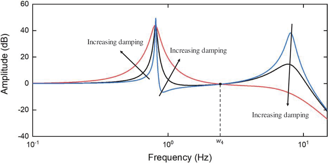
Figure 14: Amplitude-frequency characteristics of unsprung mass
Although SH-ADD control and GH-ADD control can achieve full-band vibration suppression, they can only control the sprung mass or unsprung mass, and cannot achieve full-band vibration suppression of sprung and unsprung mass.
To reduce the force of the vehicle on the road, it is necessary to reduce the vibration acceleration of the sprung and unsprung. Since the inertia force of the unsprung mass will directly act on the ground, the inertia force of the unsprung mass can be derived from the 1/4 model of the 4.1 suspension system:
It can be seen that when the vibration acceleration
where:

Figure 15: Module schematic based on improved SH-GH-ADD control strategy
5 Analysis of Vehicle Simulation Results
In order to verify the superiority of the improved SH-GH-ADD control over the SH-ADD control, the GH-ADD control and mixed SH-GH control, this study used the constructed virtual track train to carry out simulation analysis and verification of human comfort, ride comfort and road friendliness. The design speed of the virtual rail train is 70 km/h, the actual running speed is 60 km/h, and the urban road surface grade is B. Under this condition, we studied the influence of the improved SH-GH-ADD control strategy on the human-vehicle-road friendliness through simulation analysis. Considering that the three carriages of the virtual rail train have certain similarity and a large amount of data, this paper only shows the data of the lead-vehicle for analysis.
In order to determine whether the quartic vibration dose value (VDV) or the estimated vibration dose value (eVDV) is used for the objective evaluation of environmental vibration in the comfort evaluation index 2.1, it is necessary to determine the peak factor of the floor vibration during the running of the train. As shown in Fig. 16, the vibration acceleration time domain signal of the floor under the passive shock absorber is calculated. The maximum peak value is 2.201 m/s2, and the rms value is 0.639 m/s2. Therefore, the peak factor of the floor vibration during the running of the train is 3.44, so the estimated vibration dose value (eVDV) is more suitable for the evaluation of human comfort.
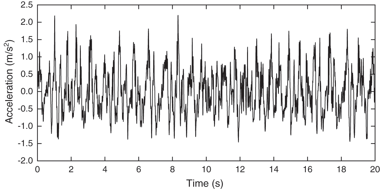
Figure 16: Acceleration response of floor under passive shock absorber
In order to fully analyze the frequency range of human comfort adaptation (0.5∼12.5 Hz), 0.5 Hz in ISO2631-1:1997 is used as the center frequency of 1/3 frequency doubling, and its lower limit frequency is 0.45; 12.5 Hz is the center frequency of 1/3 frequency doubling, and its upper limit frequency is 14 Hz. In order to characterize the daily occupational vibration exposure, the frequency-weighted acceleration
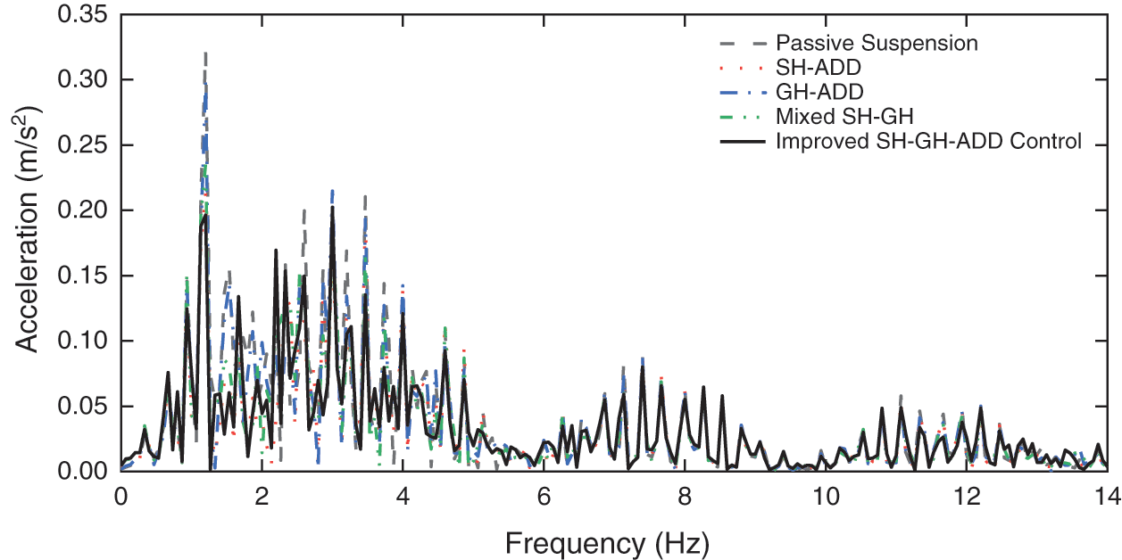
Figure 17: Acceleration frequency domain response of the floor
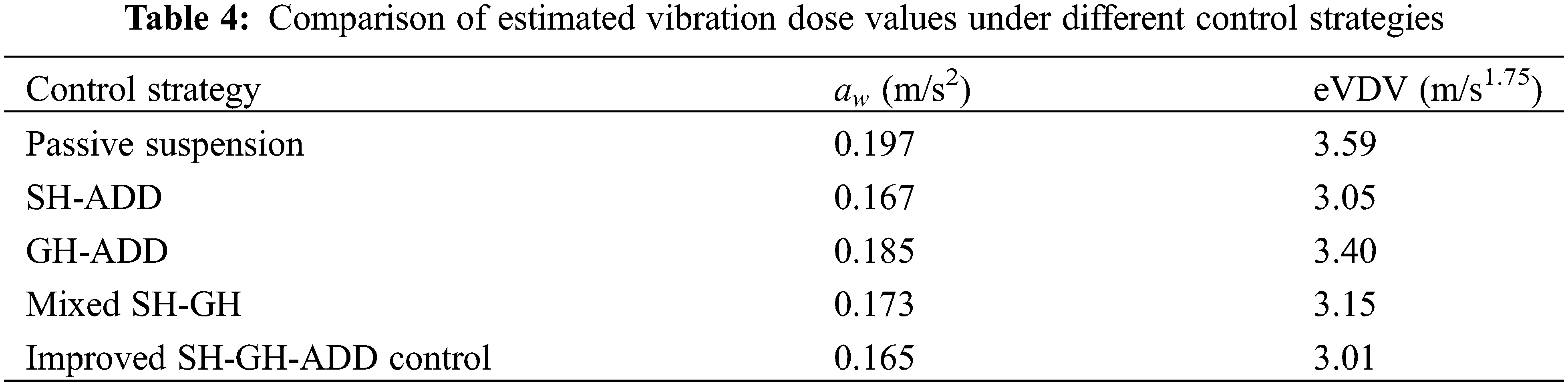
As shown in Table 4, the eVDV under various control strategies in the range of 0.45∼14 Hz have been improved compared with the passive suspension. Among them, the Improved SH-GH-ADD control has the most obvious effect on the comfort of the human body, which can effectively reduce the fatigue effect of the human body.
5.2 Vehicle Ride Comfort Analysis
According to the simulation analysis, the vibration displacement and acceleration of the lead-car floor of various control strategies is shown in Figs. 18 and 19. The floor vibration displacement of the lead-car with various control strategies is shown in Table 5. The evaluation indexes of different control strategies are calculated by the vehicle ride comfort evaluation index, as shown in Table 6.
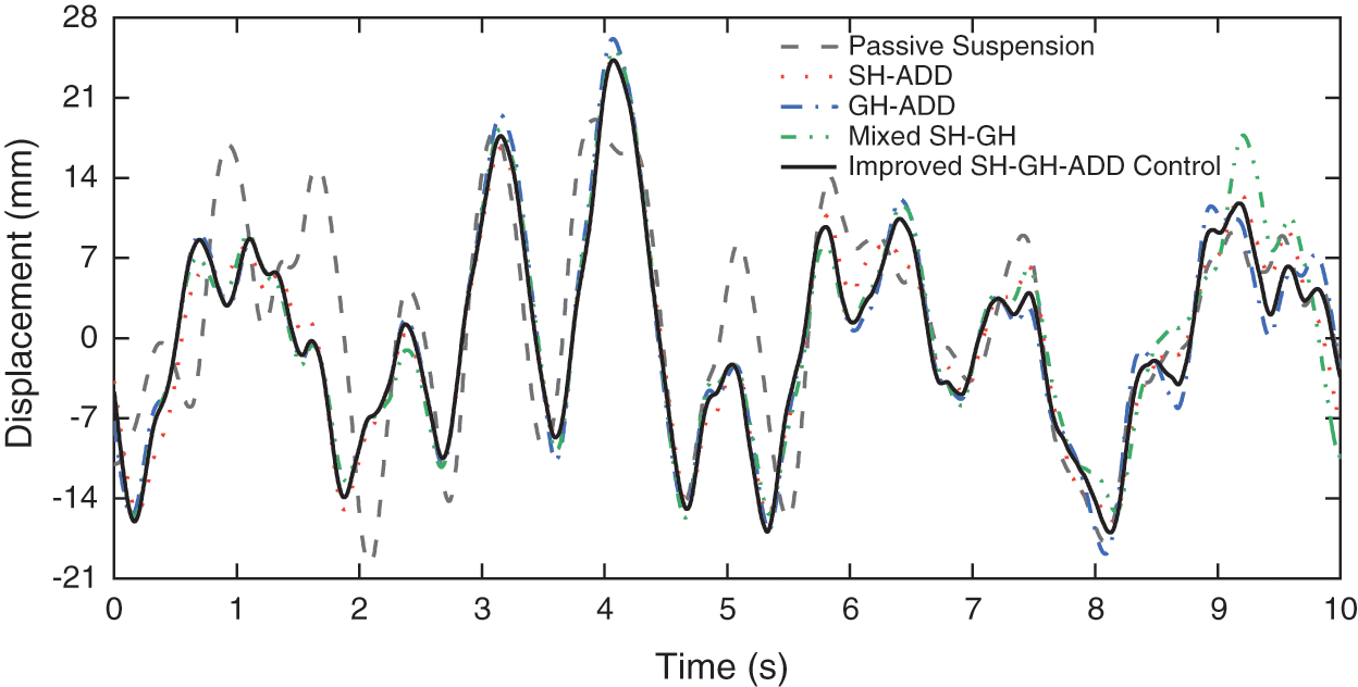
Figure 18: Time domain signal of floor vibration displacement
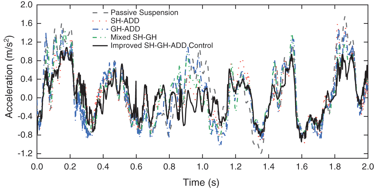
Figure 19: Time domain signal of floor vibration acceleration
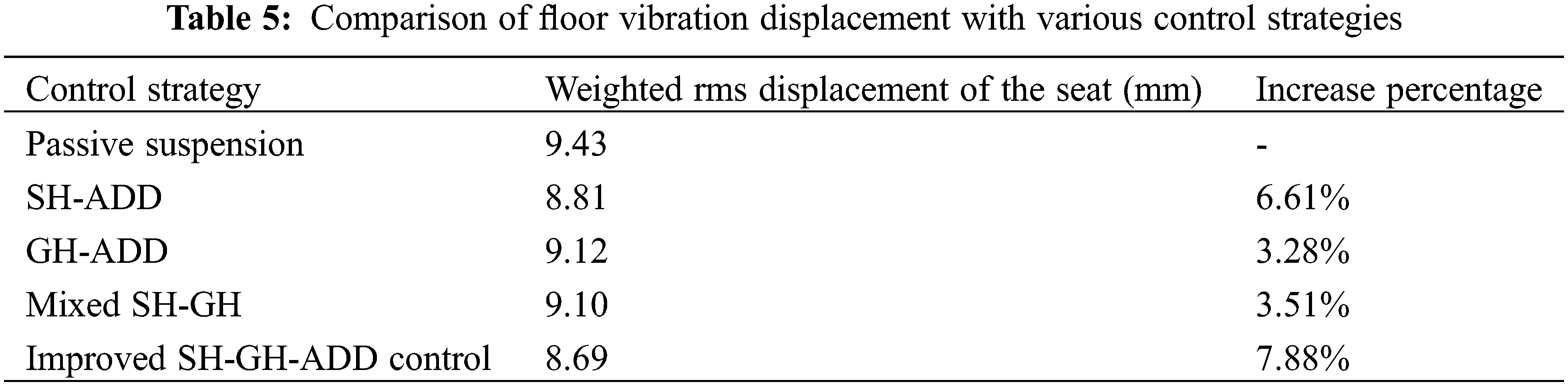
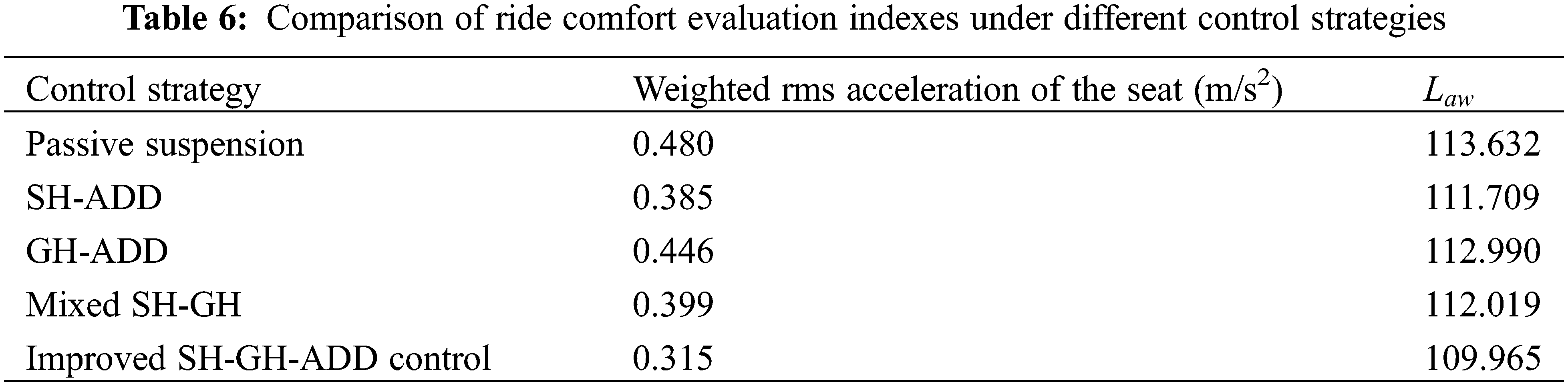
It can be seen from Tables 6 and 7 that the weighted rms displacement, acceleration and equivalent mean value
5.3 Road Friendliness Analysis
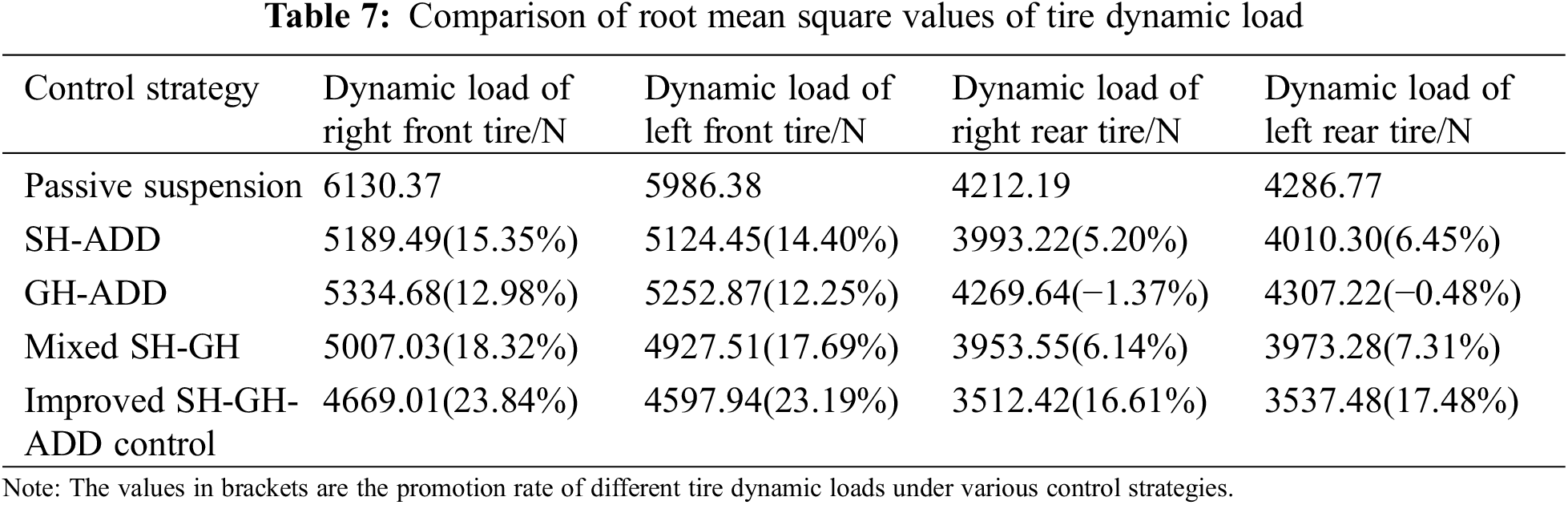
Through simulation analysis, the tire dynamic load under various control strategies is shown in Figs. 20–23 and the root mean square value of tire dynamic load is shown in Table 6.
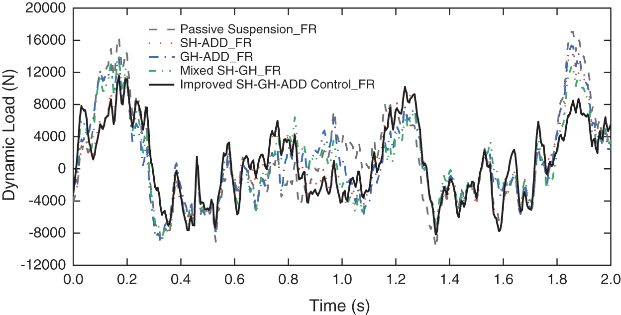
Figure 20: Dynamic load of right front tire
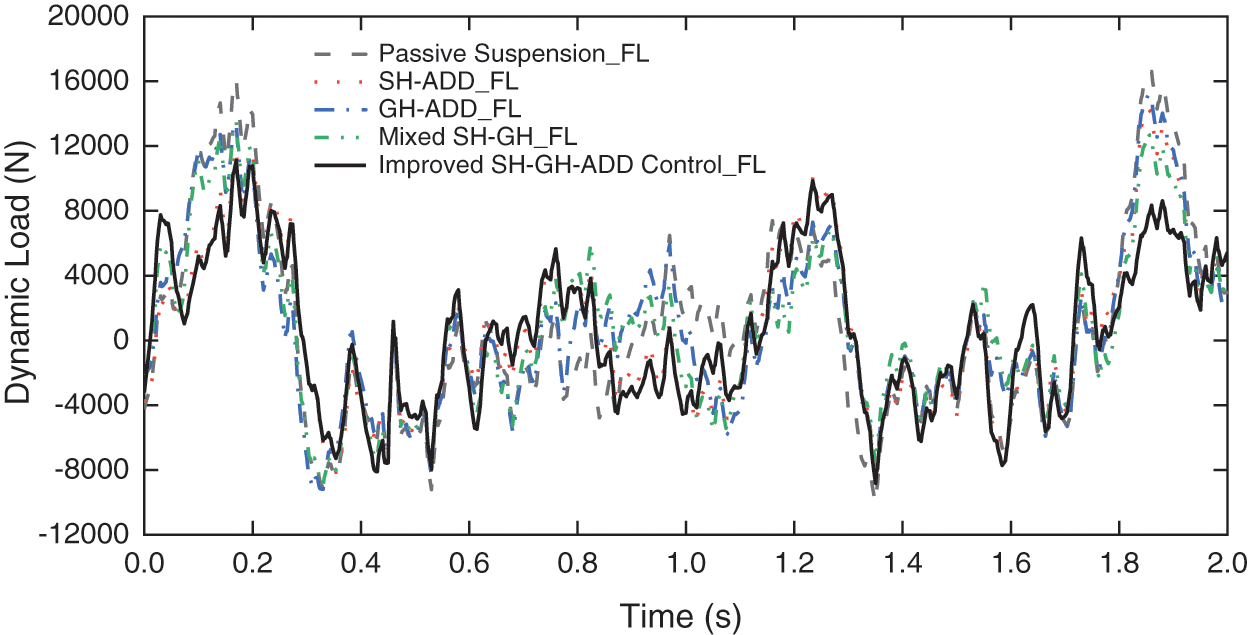
Figure 21: Dynamic load of left front tire
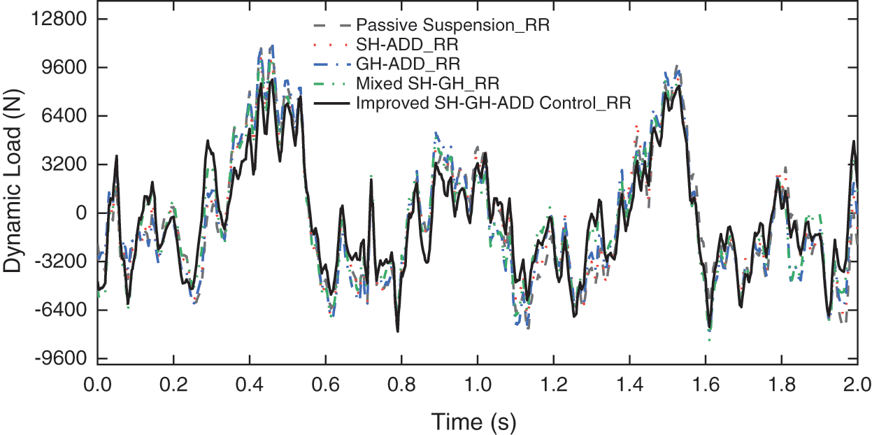
Figure 22: Dynamic load of right rear tire
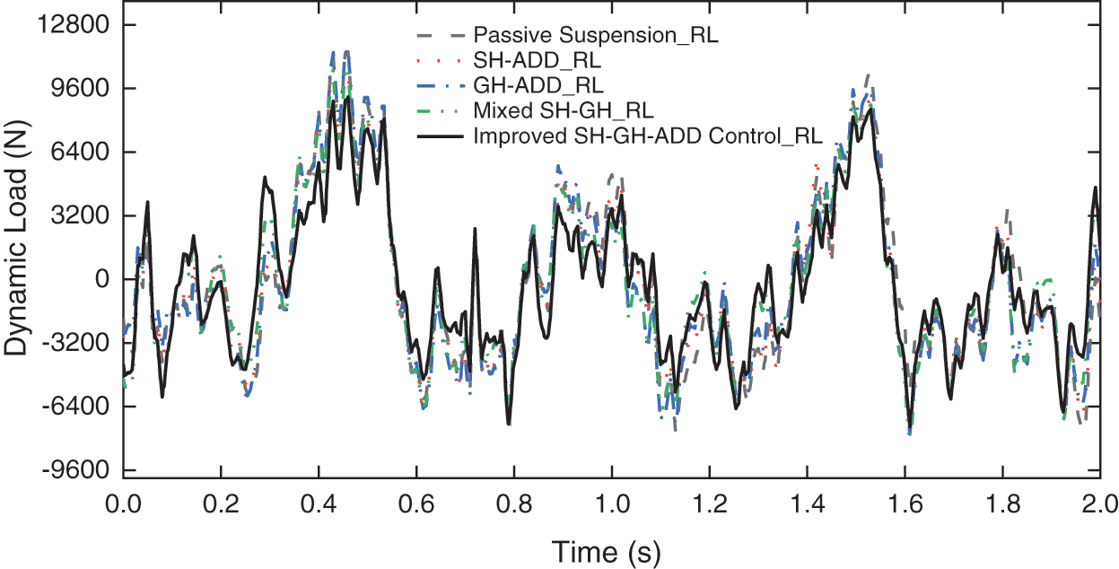
Figure 23: Dynamic load of left rear tire
From Table 7, it can be seen that the root mean square value of tire dynamic load under various control strategies is improved compared with that of passive suspension. Among them, Improved SH-GH-ADD control draws on the advantages of SH-ADD control and GH-ADD control, which greatly improves the tire dynamic load of the front and rear axles. Among the four control strategies, the proposed control strategy has obvious optimization effect on tire dynamic load.
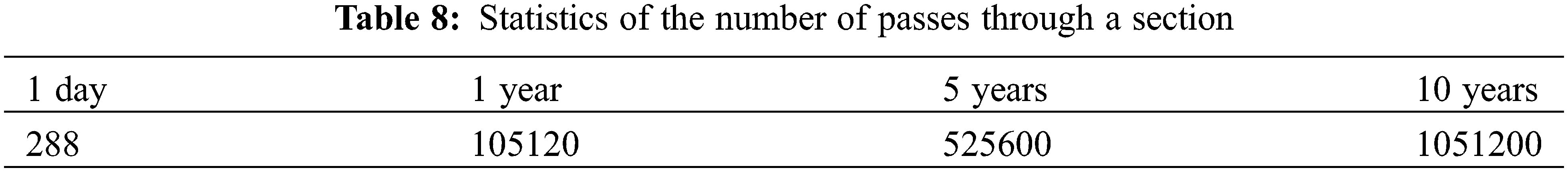
The virtual track train is driven by automatic tracking, and its load repeatedly acts on the road surface. Through the investigation, the daily running time of the virtual track train is 6:00∼22:00, and the statistical results of the number of times that the virtual track train tire passes through a section are collected [1], as shown in Table 8.
Since the road friendliness evaluation index considers the vehicle axle load, the value of the
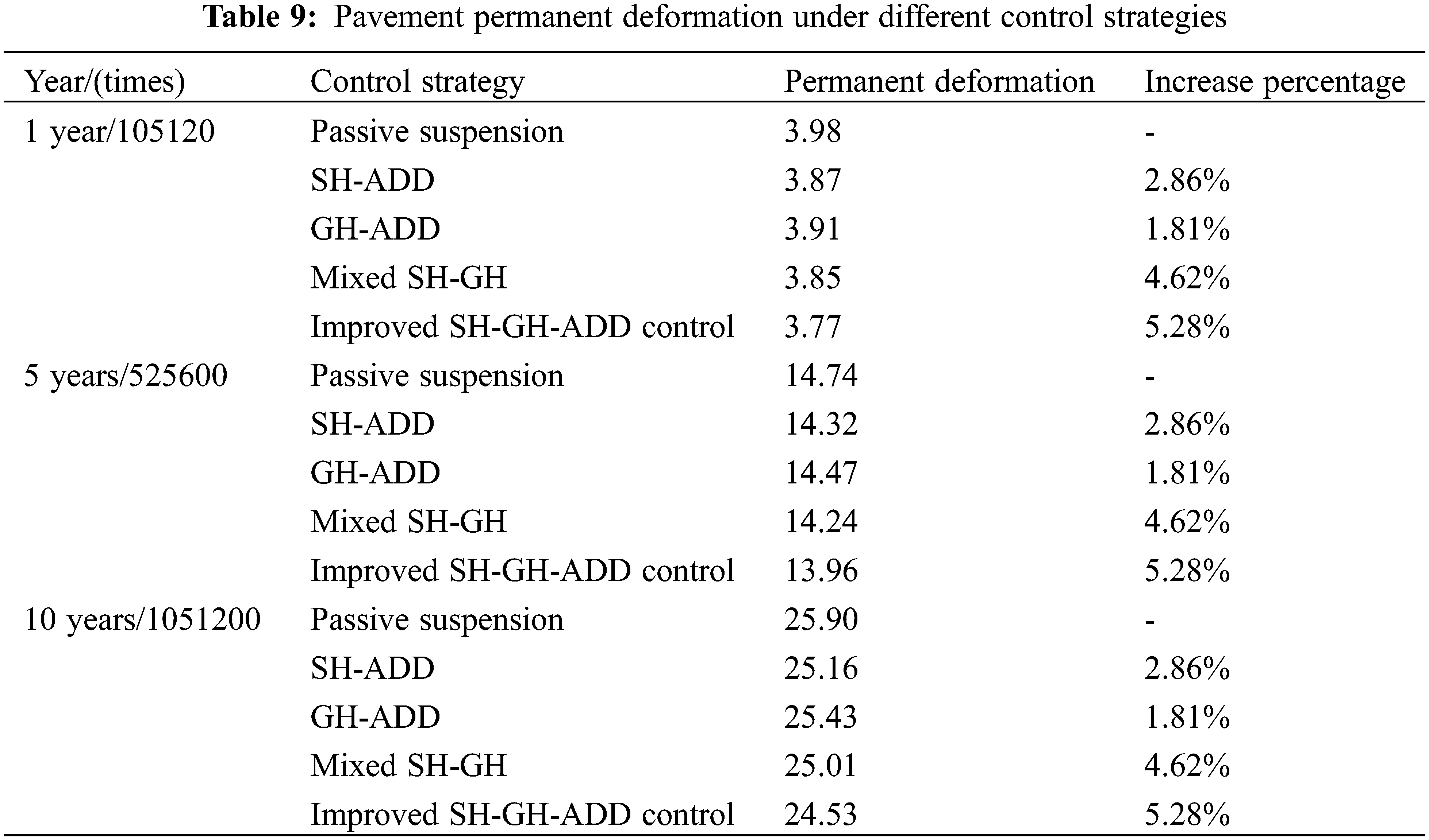
Through the permanent damage prediction equation of the road surface, the permanent damage of the vehicle to the road in different years is predicted. As shown in Table 9, the permanent deformation of the road surface under various control strategies is improved compared with the passive suspension. Among them, the improved SH-GH-ADD control has the least damage to the road surface, indicating that the control has better road friendliness than other controls.
This paper proposes an improved SH-GH-ADD control strategy for enhancing human comfort, vehicle ride comfort, and road friendliness. Firstly, the virtual rail train’s human comfort, vehicle ride comfort, and road friendliness are evaluated from multiple perspectives using the human-vehicle-road friendliness approach. Secondly, the multibody dynamics model of the virtual rail train is experimentally verified, demonstrating its high validity and correctness. This verification also confirms the reliability and practical application value of simulation analysis based on the model to some extent. Next, the advantages and disadvantages of SH-ADD, GH-ADD, and Mixed SH-GH control strategies are compared and analyzed. To reduce the vehicle’s force on the road surface and suppress body vibration simultaneously, an improved SH-GH-ADD control strategy based on unsprung mass acceleration is proposed. This strategy combines the benefits of SH-ADD and GH-ADD control strategies. Finally, using the hub-driven virtual rail train dynamics model, the correctness and effectiveness of the improved SH-GH-ADD control strategy are verified by taking human comfort, vehicle ride comfort, and road friendliness as evaluation indices. The results indicate that SH-ADD, GH-ADD, Mixed SH-GH, and improved SH-GH-ADD control strategies all improve the human-vehicle-road friendliness of the virtual rail train, with the improved SH-GH-ADD control strategy having the most significant impact.
Acknowledgement: The authors would like to acknowledge the support from the Sichuan Provincial Natural Science Foundation and the facilities provided by the Institute of Energy and Power Research at Southwest Jiaotong University for the experimental research.
Funding Statement: This research was funded by Natural Science Foundation of Sichuan Province (2023NSFSC0395), the Sichuan Science and Technology Program (2022ZH CG0061), the SWJTU Science and Technology Innovation Project (2682022CX008).
Author Contributions: Writing-original draft: Yangyang Bao; supervision, funding acquisition: Mingliang Yang, Weiping Ding; methodology: Haibo Huang; writing—review and editing: Liyuan Liu, Honglin Zhu. All authors reviewed the results and approved the final version of the manuscript.
Availability of Data and Materials: The data used to support the findings of this study are available from the corresponding author upon request.
Conflicts of Interest: The authors declare that they have no conflicts of interest to report regarding the present study.
References
1. Wang, C., Zhang, J., Zhou, H., Lu, H. (2021). Dynamic response and permanent deformation analysis of asphalt pavement under the virtual rail train. Journal of Tongji University (Natural Science), 49(1), 60–66. https://doi.org/10.11908/j.issn.0253-374x.20274 [Google Scholar] [CrossRef]
2. Du, H., Zhang, N., Fazel, N. (2011). Robust control of vehicle electrorheological suspension subject to measurement noises. Vehicle System Dynamics, 49(1–2), 257–275. https://doi.org/10.1080/00423110903288336 [Google Scholar] [CrossRef]
3. Nguyen, D. N., Nguyen, T. A. (2022). A novel hybrid control algorithm sliding mode-PID for the active suspension system with state multivariable. Complex, 2022, 1–14. https://doi.org/10.1155/2022/9527384 [Google Scholar] [CrossRef]
4. Yokoyama, M., Hedrick, J. K., Toyama, S. (2001). A model following sliding mode controller for semi-active suspension systems with MR dampers. Proceedings of the 2001 American Control Conference, pp. 2652–2657. Arlington, VA, USA. https://doi.org/10.1109/ACC.2001.946276 [Google Scholar] [CrossRef]
5. Huang, X., Huang, H., Peng, Y., Ralescu, A. L., Sun, S. (2023). Dissipativity-based adaptive integral sliding mode control of Takagi-Sugeno fuzzy descriptor systems. IET Control Theory & Applications, 17(1), 53–73. [Google Scholar]
6. Nguyen, T. A. (2023). A novel approach with a fuzzy sliding mode proportional integral control algorithm tuned by fuzzy method (FSMPIF). Scientific Reports, 13(1), 7327. https://doi.org/10.1038/s41598-023-34455-7 [Google Scholar] [PubMed] [CrossRef]
7. Nguyen, D. N., Nguyen, T. A. (2023). Proposing an original control algorithm for the active suspension system to improve vehicle vibration: Adaptive fuzzy sliding mode proportional-integral-derivative tuned by the fuzzy (AFSPIDF). Heliyon, 9(3), e14210. https://doi.org/10.1016/j.heliyon.2023.e14210 [Google Scholar] [PubMed] [CrossRef]
8. Karnopp, D., Crosby, M. J., Harwood, R. A. (1974). Vibration control using semi-active force generators. Journal of Engineering for Industry, 96(2), 619–626. https://doi.org/10.1115/1.3438373 [Google Scholar] [CrossRef]
9. Valášek, M., Novák, M., Šika, Z., Vaculín, O. (1997). Extended ground-hook-new concept of semi-active control of truck’s suspension. Vehicle System Dynamics, 27(5–6), 289–303. https://doi.org/10.1080/00423119708969333 [Google Scholar] [CrossRef]
10. Savaresi, S. M., Silani, E., Bittanti, S. (2005). Acceleration-driven-damper (ADDAn optimal control algorithm for comfort-oriented semiactive suspensions. Journal of Dynamic Systems Measurement & Control, 127(2). https://doi.org/10.1115/1.1898241 [Google Scholar] [CrossRef]
11. Savaresi, S. M., Spelta, C. (2007). Mixed sky-hook and ADD: Approaching the filtering limits of a semi-active suspension. Journal of Dynamic Systems, Measurement, and Control, 129(4), 382–392. https://doi.org/10.1115/1.2745846 [Google Scholar] [CrossRef]
12. Wang, Y. (2020). Research on control strategy of semi-active suspension considering phase compensation (Ph.D. Thesis). Jilin University, China. [Google Scholar]
13. Guo, K., Sui, J., Guo, Y. (2013). Semi-active control method for a high-speed railway vehicle lateral damper based on skyhook and groundhook hybrid damping. Journal of Vibration and Shock, 32(2), 18–23. https://doi.org/10.13465/j.cnki.jvs.2013.02.028 [Google Scholar] [CrossRef]
14. Huang, H., Lim, T. C., Wu, J., Ding, W., Pang, J. (2023). Multitarget prediction and optimization of pure electric vehicle tire/road airborne noise sound quality based on a knowledge and data-driven method. Mechanical Systems and Signal Processing, 197, 110361. https://doi.org/10.1016/j.ymssp.2023.110361 [Google Scholar] [CrossRef]
15. Zhao, L., He, Q. (1992). Human response to low frequency vibration below 1.0 Hz. Automotive Engineering, 1992(2), 65–69+80. https://doi.org/10.19562/j.chinasae.qcgc.1992.02.001 [Google Scholar] [CrossRef]
16. Huang, H., Huang, X., Ding, W., Yang, M., Yu, X. (2022). Vehicle vibro-acoustical comfort optimization using a multi-objective interval analysis method. Expert Systems with Applications, 213, 119001. https://doi.org/10.1016/j.eswa.2022.119001 [Google Scholar] [CrossRef]
17. Dong, S., Zhu, Y. (2004). Effects of environmental vibration on man. Noise and Vibration Control, 24(3), 22–25. https://doi.org/10.3969/j.issn.1006-1355.2004.03.007 [Google Scholar] [CrossRef]
18. Huang, H., Huang, X., Ding, W., Zhang, S., Pang, J. (2023). Optimization of electric vehicle sound package based on LSTM with an adaptive learning rate forest and multiple-level multiple-object method. Mechanical Systems and Signal Processing, 187, 109932. https://doi.org/10.1016/j.ymssp.2022.109932 [Google Scholar] [CrossRef]
19. Yu, Z. (2018). Automobile theory. 6th editionBeijing, China: Mechanical Industry Press. [Google Scholar]
20. Duarte, M. L., Araújo, P. A., Horta, F. C., Vecchio, S. D., Carvalho, L. A. (2018). Correlation between weighted acceleration, vibration dose value and exposure time on whole body vibration comfort levels evaluation. Safety Science, 218–224. https://doi.org/10.1016/j.ssci.2017.11.008 [Google Scholar] [CrossRef]
21. Yang, Y., Liu, P., Yin, J. (2014). Research on assessment of fourth power vibration dose value in environmental vibration caused by metro. 21st International Congress on Sound and Vibration 2014: ICSV 21, pp. 1092–1099. Beijing, China. [Google Scholar]
22. Mechanical vibration and shock-evaluation of human exposure to whole-body vibration–Part 1: General requirements. [Google Scholar]
23. Chen, J. (2008). MSC.ADAMS technology and engineering analysis example. Beijing, China: China Water & Power Press. [Google Scholar]
24. Theyse, H. L. (1997). Mechanistic-empirical modeling of the permanent deformation of unbound pavement layers. 8th International Conference on Asphalt Pavements, vol. 2, pp. 1579–1594. Seattle, USA. [Google Scholar]
25. Liu, B., Yao, Z. (2002). Introduction about revision of specifications of cement concrete pavement design for highway. Highway, 1–7. https://doi.org/10.3969/j.issn.0451-0712.2002.08.001 [Google Scholar] [CrossRef]
26. Zhang, X., Ding, J. (2021). Firefly algorithm for multi-body system dynamics differential-algebraic equations. Journal of Dynamics and Control, 19(2), 85–90. https://doi.org/10.6052/1672-6553-2020-113 [Google Scholar] [CrossRef]
27. Zhang, X. (2020). Intelligent algorithm for solving differential-algebraic equations of multibody system dynamics. Qingdao, China: Qingdao University. https://doi.org/10.27262/d.cnki.gqdau.2020.001759 [Google Scholar] [CrossRef]
28. Kan, Z., Peng, H., Chen, B. (2017). Rigid body system dynamic with the accurate jacobian matrix of spring-damper-actuator. Chinese Journal of Theoretical and Applied Mechanics, 49(5), 1103–1114. https://doi.org/10.6052/0459-1879-17-030 [Google Scholar] [CrossRef]
29. Savaresi, S. M. (2010). Classical control for semi-active suspension system. Semi-Active Suspension Control Design for Vehicles, 107–120. https://doi.org/10.1016/b978-0-08-096678-6.00006-7 [Google Scholar] [CrossRef]
30. Fan, D., Dai, P., Yang, M., Jia, W., Jia, X. et al. (2022). Research on maglev vibration isolation technology for vehicle road noise control. SAE International Journal of Vehicle Dynamics, Stability, and NVH, 6(3), 233–245. [Google Scholar]
31. Jin, T., Liu, Z., Sun, S., Ren, Z., Deng, L. et al. (2020). Development and evaluation of a versatile semi-active suspension system for high-speed railway vehicles. Mechanical Systems and Signal Processing, 135, 106338. https://doi.org/10.1016/j.ymssp.2019.106338 [Google Scholar] [CrossRef]
32. Yan, W., Dong, D., Wang, W., Wu, C., Liu, Z. et al. (2011). On fuzzy control strategy of nonlinear semi-active suspension system. Control Engineering of China. https://doi.org/10.14107/j.cnki.kzgc.2011.06.010 [Google Scholar] [CrossRef]
Cite This Article
 Copyright © 2023 The Author(s). Published by Tech Science Press.
This work is licensed under a Creative Commons Attribution 4.0 International License , which permits unrestricted use, distribution, and reproduction in any medium, provided the original work is properly cited.
 Downloads
 Citation Tools