
 Submit a Paper
 Open Access
ARTICLE

Study of Axial Vibration of a Motor-Compressor System Using Operational Modal Analysis
1 Engineering Department, Malaysia Refining Company (Petronas), Pesiaran Penapisan, Sungai Udang, Melaka, 76300, Malaysia
2 Center for Advance Research on Energy, Universiti Teknikal Malaysia Melaka, Hang Tuah Jaya, Durian Tunggal, Melaka, 76100, Malaysia
3 Fakulti Teknologi dan Kejuruteraan Mekanikal, Universiti Teknikal Malaysia Melaka, Hang Tuah Jaya, Durian Tunggal, Melaka, 76100, Malaysia
* Corresponding Authors: Reduan Mat Dan. Email: ; Azma Putra. Email:
Sound & Vibration 2023, 57, 119-131. https://doi.org/10.32604/sv.2023.045029
Received 15 August 2023; Accepted 20 October 2023; Issue published 20 December 2023
 View Full Text
 Download PDF
Abstract
A case study of excessive vibration on a motor-compressor system is presented in this paper. After barely two months of operation, the reciprocating compressor motor’s routine monitoring revealed excessive axial vibration amplitude. For this reason, the Operational Modal Analysis (OMA) was carried out in order to identify the primary cause. According to the investigation, one of the harmonic components which was 18 times the motor’s running speed matched with a resonance frequency of 112 Hz. According to OMA study, the motor was vibrating in torsional motion because the compressor’s load had stimulated the entire motor-compressor unit at this resonance frequency. The analysis also demonstrates the bulging effect of the motor shaft’s axial vibration on the motor’s endplate.Keywords
Failures of vital equipment in an oil refinery, including a reciprocating compressor and a high-voltage motor, can have a substantial financial impact on the business. As a result, the plant’s maintenance plan must guarantee equipment reliability at the greatest level of machine integrity. The best way to guarantee that early failure detection will result in prompt and appropriate maintenance activity is to use predictive maintenance as a technique. This will boost the machinery’s reliability. Predictive maintenance uses a variety of methods, such as vibration, ultrasonic, and oil and wear debris analysis, and thermography, to evaluate the “health” of rotating machinery.
Mass imbalance, coupling misalignment, soft foot, and looseness are a few of the main sources of vibration in rotating machinery. For instance, vibration in an axial direction (back and forth along the shaft axis) can be caused by a misaligned shaft. In addition, coupling component unbalance, bent shafts, bearing misalignments, and axial resonance can all cause axial vibration [1]. The axial vibration of a rotating machine has been the subject of numerous published publications and case studies. The dynamic study of a linked propeller shaft system subjected to axial vibration from the propeller excitation was investigated by Amirudin et al. [2]. With the help of the analytical hierarchy process, an auto-regressive and moving average model, and high-speed diesel engines, Liang et al. [3] provided a way to pinpoint the primary source of the axial vibration of crankshafts. The axial vibration analysis of a vertical hydro-generator unit was presented by Long et al. [4]. It is discovered that the connection between the thrust head and the mirror plate is the cause of this axial vibration. Arifin [5] provided the balancing solution along with a case study of an axial fan engine’s vibration unbalance.
A method for analysing axial vibration signals to identify bearing problems in induction motors was presented by Medued et al. [6]. The impact of axial vibration on regenerative chatter in robotic milling was emphasized by Mohammadi et al. [7]. A numerical model was created to illustrate how vibration affects process stability. Fikre et al. [8] investigated torsional vibration that caused repeated coupling failures at the reciprocating compressor and create a finite-element model of the entire drivetrain, including the non-linear rubber coupling and the periodic excitation torque (inertial and gas forces). Concurrently, Zhao et al. [9] discovered that the fundamental cause of crank cracking due to fatigue failure is the inertia mass of the initial crankshaft, which leads to extra stress with resonance. The primary dynamic loads on reciprocating compressors, according to Kacani [10], are the shaking forces brought on by pressure pulsation, the forces of inertia and gas, and the additional forces brought on by the drive train’s torsion vibration.
This study presents the results of vibration analysis on a motor-reciprocating compressor system. With a rigid coupling, the 3400 kW motor is coupled to the compressor and runs at a regular speed of 371 rpm. At the time of the measurement, the motor was thought to have just been put into service. Even though the machinery was operating without any issues, the axial directions showed a significant vibration signature during the routine vibration check. If this anomaly is ignored, the bearing will continue to deteriorate. Operational modal analysis (OMA) was carried out to identify the primary cause of the high axial vibration in order to resolve the problem.
The study involved three main steps:
1. Vibration amplitude measurement
2. Operation modal analysis
3. Final analysis
2.1 Vibration Amplitude Measurement
Two types of accelerometers were utilized for the purpose of monitoring vibration signals: single-direction accelerometers and radial-direction accelerometers. Single-axis accelerometers were employed to measure various locations on motor and compressor housings, whereas radial accelerometers were utilized to monitor vibration on bearing casings. Following the commissioning of the motor, the rotating machinery team conducted several sets of vibration measurements to record the overall vibration (expressed as velocity root mean square) at the usual operating speed, while the machinery was subjected to process loads. Vibration measurements were conducted at the non-drive end (NDE) and drive end (DE) positions of the shaft for each motor and compressor. The single direction accelerometers were positioned at certain places in the horizontal, vertical, and axial directions, as depicted in Fig. 1.
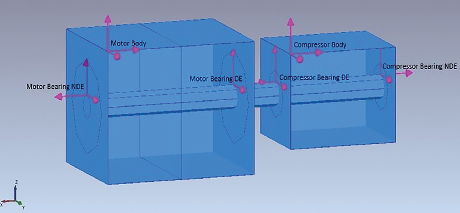
Figure 1: Diagram of the motor-compressor system
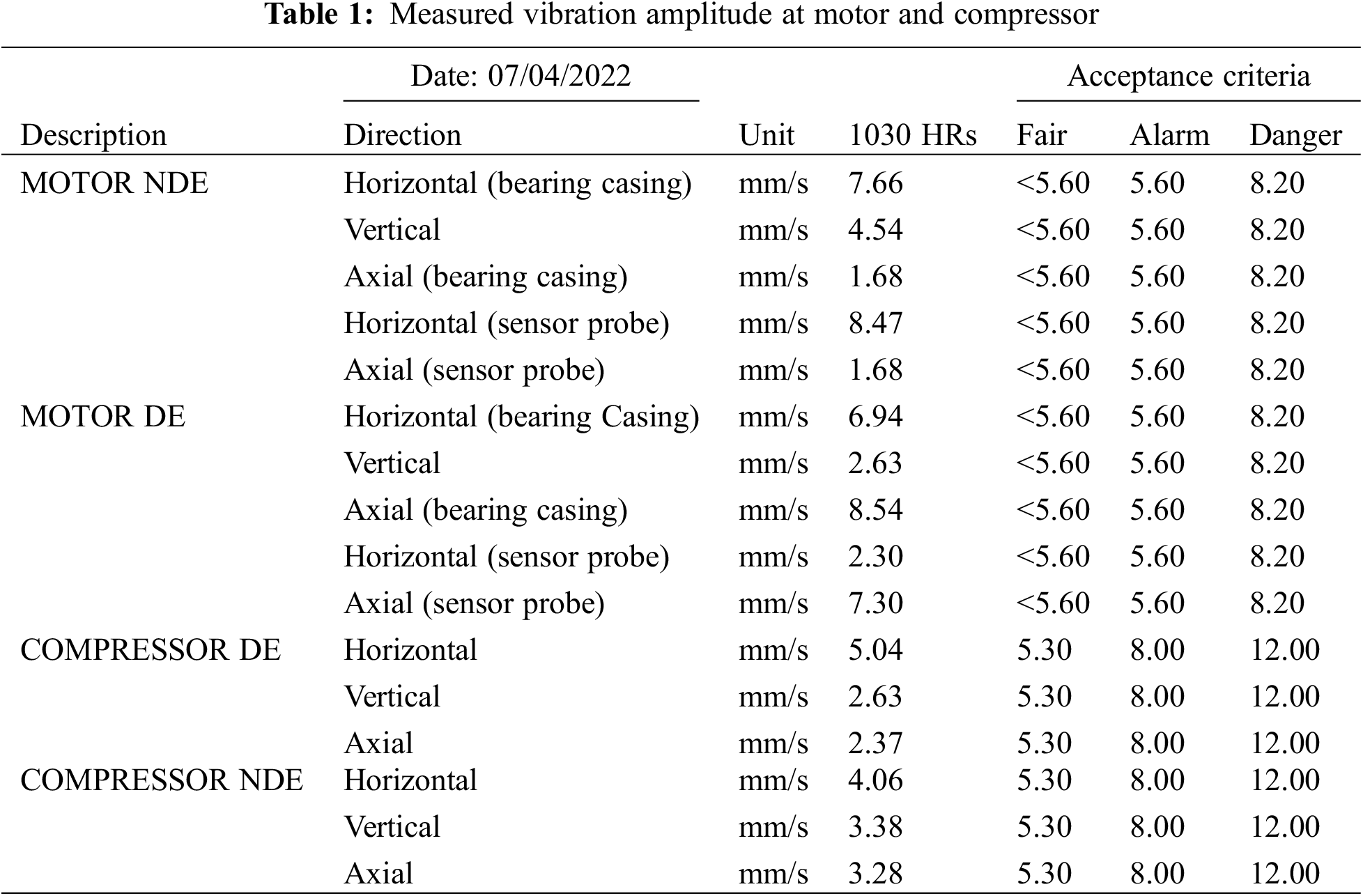
Table 1 presents a dataset obtained from a specific process load, as measured during the study. It illustrates a significant magnitude of vibration observed at the motor, both in the axial direction at the non-drive end (NDE) and drive end (DE). Based on the guidelines provided by ISO 10816-6 [11], the motor’s vibration, exceeding a threshold of 8 mm/s, is classified within Zone D, commonly referred to as the danger zone. This classification indicates that the severity of the vibration is significant enough to potentially result in damage to the machine.
Figs. 2a and 2b show the measured velocity spectrum from another set of recorded data, which features harmonics of the turning shaft due to the pulsation produced by the piston movement from the compressor. It can also be seen that distinct high amplitude (especially at DE, Fig. 2b) is recorded at frequency 112 Hz, which is 18 times the speed of the turning shaft (18X component). It is therefore of interest to investigate what possibly caused the vibration at this specific frequency. The Operational Modal Analysis (OMA) was conducted to observe the vibration behavior of the motor.
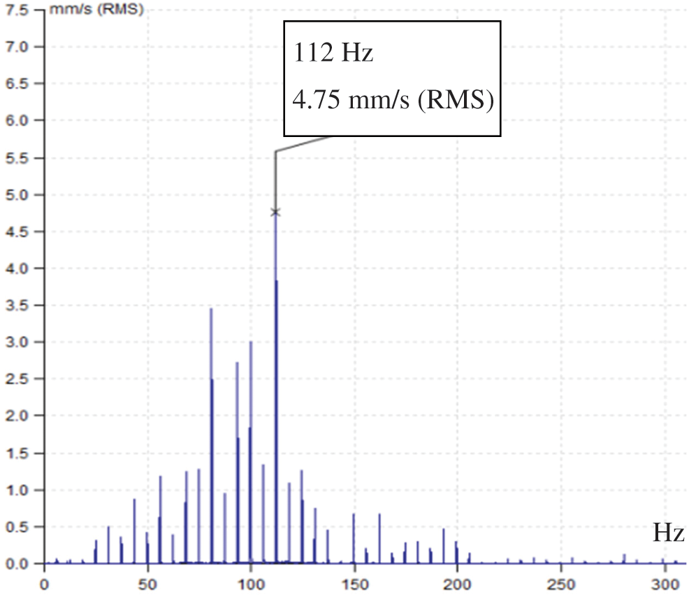
Figure 2a: Velocity spectrum at the motor in axial direction at NDE
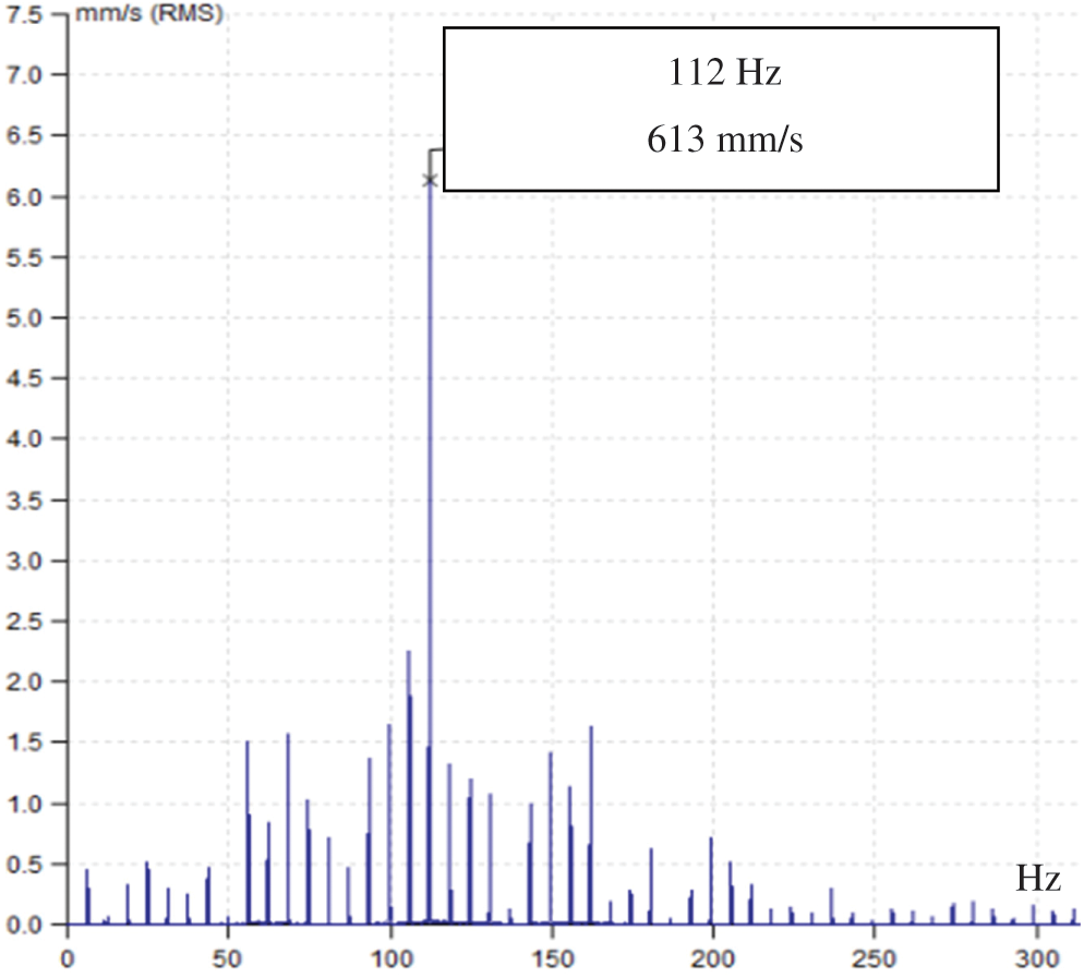
Figure 2b: Velocity spectrum at the motor in axial direction at DE
2.2 Operational Modal Analysis
Operating Modal Analysis (OMA) is a technique utilized to ascertain the modal characteristics of a structure based on the vibration data collected during the structure’s operating state. In contrast to standard Experimental Modal Analysis (EMA), the proposed method does not necessitate the application of an external force. EMA typically involves subjecting the structure to a stationary state, disconnected from its operational state, and inducing force excitation by means such as an impact hammer or electromagnetic shaker [12].
Consequently, the OMA possesses a distinct advantage in scenarios where artificially inducing vibrations in a mechanical structure proves challenging due to factors such as its dimensions, placement, or geographical setting. Nevertheless, due to the absence of input force data in the OMA, the method must operate under the premise that the input excitation possesses broadband energy, specifically in the form of a white noise signal. The diagram depicted in Fig. 3 is used for illustrative purposes. The approach yields modal features such as natural frequencies, mode shapes, and damping.
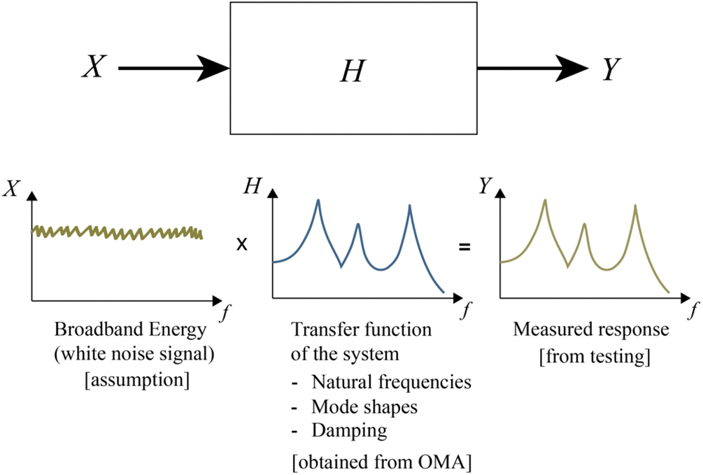
Figure 3: Illustrative diagram of the OMA method
Fig. 4 shows some locations of the accelerometers for OMA measurement. The measurement was divided into three sets:
a. The initial measurement set (Set-1) contained a total of eighteen (18) accelerometers strategically positioned throughout the motor and compressor of the machine. The location of the measurement point is depicted in Fig. 4. The measurement is conducted concurrently in order to acquire the data necessary for visualizing the relative motion between the motor and the compressor. The data acquired at each point encompassed measurements of vibration in the horizontal (Y-axis), vertical (Z-axis), and axial (X-axis) axes.
b. The second round of measurements (Set-2) involved the placement of a total of sixteen (16) accelerometers on the bearing case at both the drive end (DE) and non-drive end (NDE) of the motor and compressor. These accelerometers were positioned in the radial directions, aligned with the rotation of the shaft. This is to see the relative motion between each plane of the point of measurement as shown in Fig. 5.
c. The third measurement set (Set-3) was conducted at the motor end-plate, both at the drive end (DE) and non-drive end (NDE). Twenty (20) accelerometers were utilized throughout each DE or NDE. The recording of just axial directions was conducted with the purpose of observing the bulging impact on the endplate. The diagram is depicted in Fig. 6.
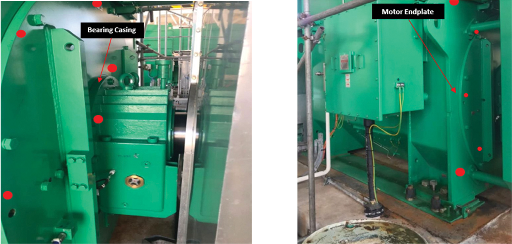
Figure 4: Location of the measurement points
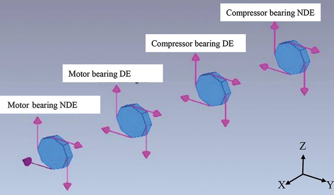
Figure 5: Diagram of the bearing casing across the shaft. The arrow shows the location and measurement directions of the accelerometer
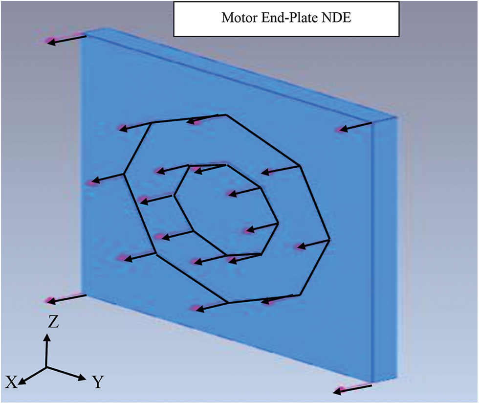
Figure 6: Diagram of the motor endplate. The arrow shows the location and measurement directions of the accelerometer
Fig. 7 displays the plot of the Singular Value Decomposition (SVD) derived from the post-processing of Operational Modal Analysis (OMA) conducted on the motor-compressor body. Three significant modes were obtained by the use of automatic mode estimate in the OMA post-processing software.
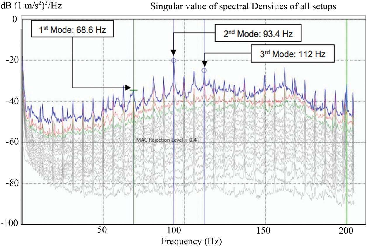
Figure 7: SVD plot from the Set-1 measurement (body of motor-compressor)
The three natural frequencies that have been emphasized are 68.6, 93.4, and 112.2 Hz. Fig. 8 displays the mode shape corresponding to each frequency. At a frequency of 68.6 Hz, it was noticed that the endplate of the motor exhibited the greatest deflection in the axial direction, with both ends bulging outward along the x-axis. At a frequency of 93.4 Hz, it was observed that both the motor and the compressor exhibited an out-of-phase movement. At a frequency of 112.2 Hz, the motor exhibited a phenomenon commonly referred to as “wobbling,” which suggests that the motor’s shaft underwent torsional motion, deviating off its rotational centreline.
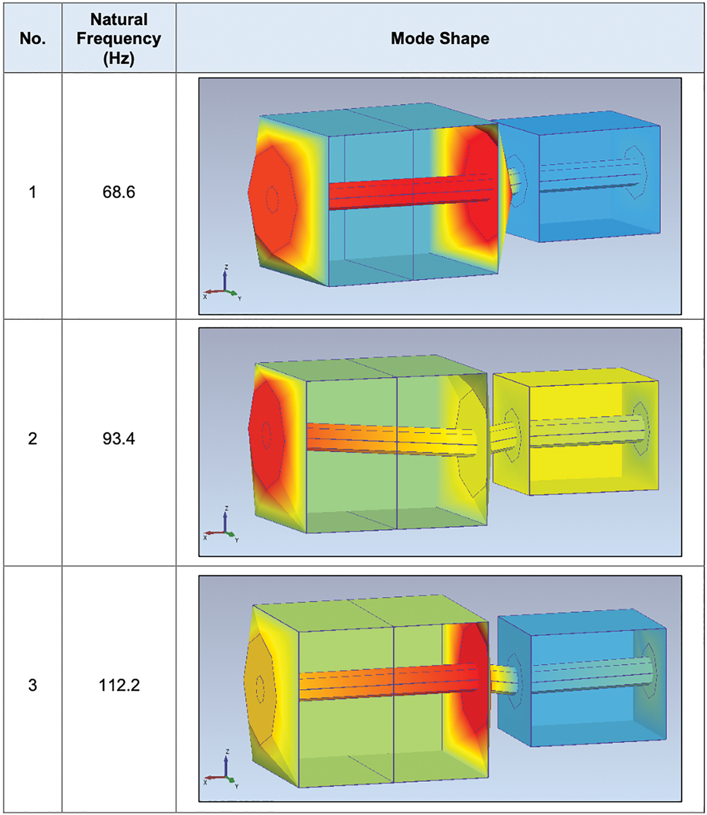
Figure 8: The mode shape of the motor-compressor system at particular natural frequency
The measured frequency of 112 Hz in the OMA measurement aligns with the natural frequency of the system. This indicates that the observed vibration in Figs. 2a and 2b was mostly caused by resonance, namely the occurrence of the 18X component coinciding with the structural natural frequency of 112 Hz.
The reciprocating compressor’s pulsation generally generates a vibration spectrum with harmonic patterns at various running speeds, which can then be transmitted to the driven equipment, such as the motor. The torsional vibration in the reciprocal compressor-motor system was caused by harmonic excitations. Resonance is observed when the stimulation frequency of a vibrating system aligns with its natural frequency. The investigation revealed, through the conducted Operational Modal Analysis (OMA), that one of the observed torsional natural frequencies corresponded closely to the 18 times running pace, with a value of 112 Hz. Resonance, as a phenomenon, has the potential to be amplified in all directions, however its impact is particularly pronounced on the weakest point or structure. Therefore, it is necessary to elucidate the reasons behind the phenomenon of increased amplification of axial direction vibrations when the running pace reaches 18 times the normal speed.
Fig. 9 shows the SVD (Singular Value Decomposition) plot from the Set-2 measurement (around the bearing casings). Here, 112 Hz again appear as one of the highlighted mode shapes. The torsional motion can be observed from the mode shape simulation shown in Fig. 10, which supported the finding of rotational motion in Fig. 8.
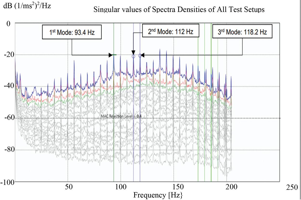
Figure 9: SVD plot from the Set-2 measurement (bearing casings)
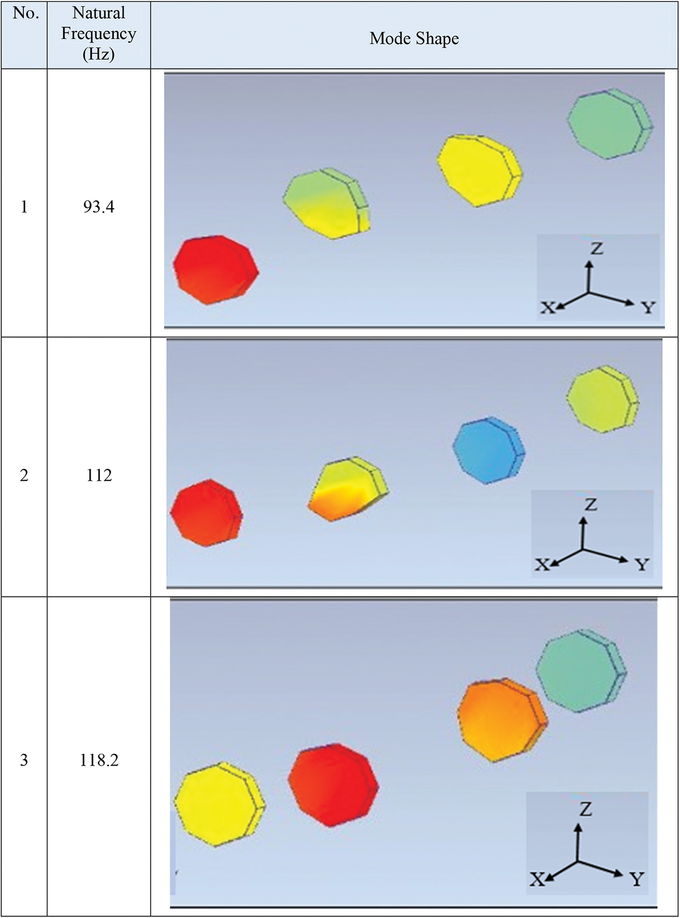
Figure 10: The mode shape of the bearing casing at particular natural frequency
Fig. 11 shows the SVD (Singular Value Decomposition) plot from the Set-3 measurement (endplate). Again here, 112 Hz is highlighted as one of the natural frequencies.
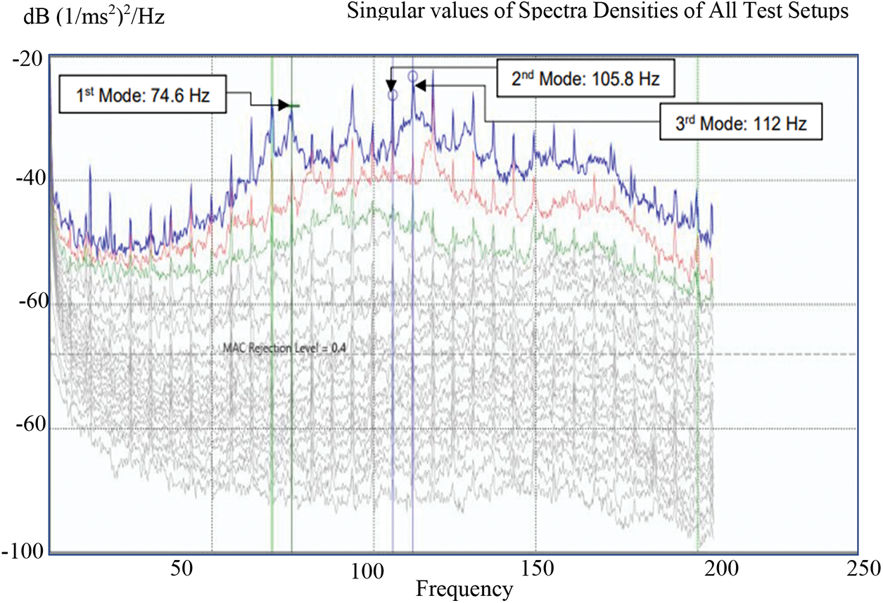
Figure 11: SVD plot from Set-3 measurement (endplate-NDE)
Fig. 12 presents the mode shape of the endplate of the motor NDE. All the modes here show the bulging effect at endplate. The same phenomenon was also found on the endplate at the DE side. The pulsation from the piston of the compressor (18X component) excites the structural natural frequency at 112 Hz. The structural rigidity was suspected to be weak at this frequency. The uneven load in the compressor could also cause the excitation force to be amplified and excited the resonance at 18X.
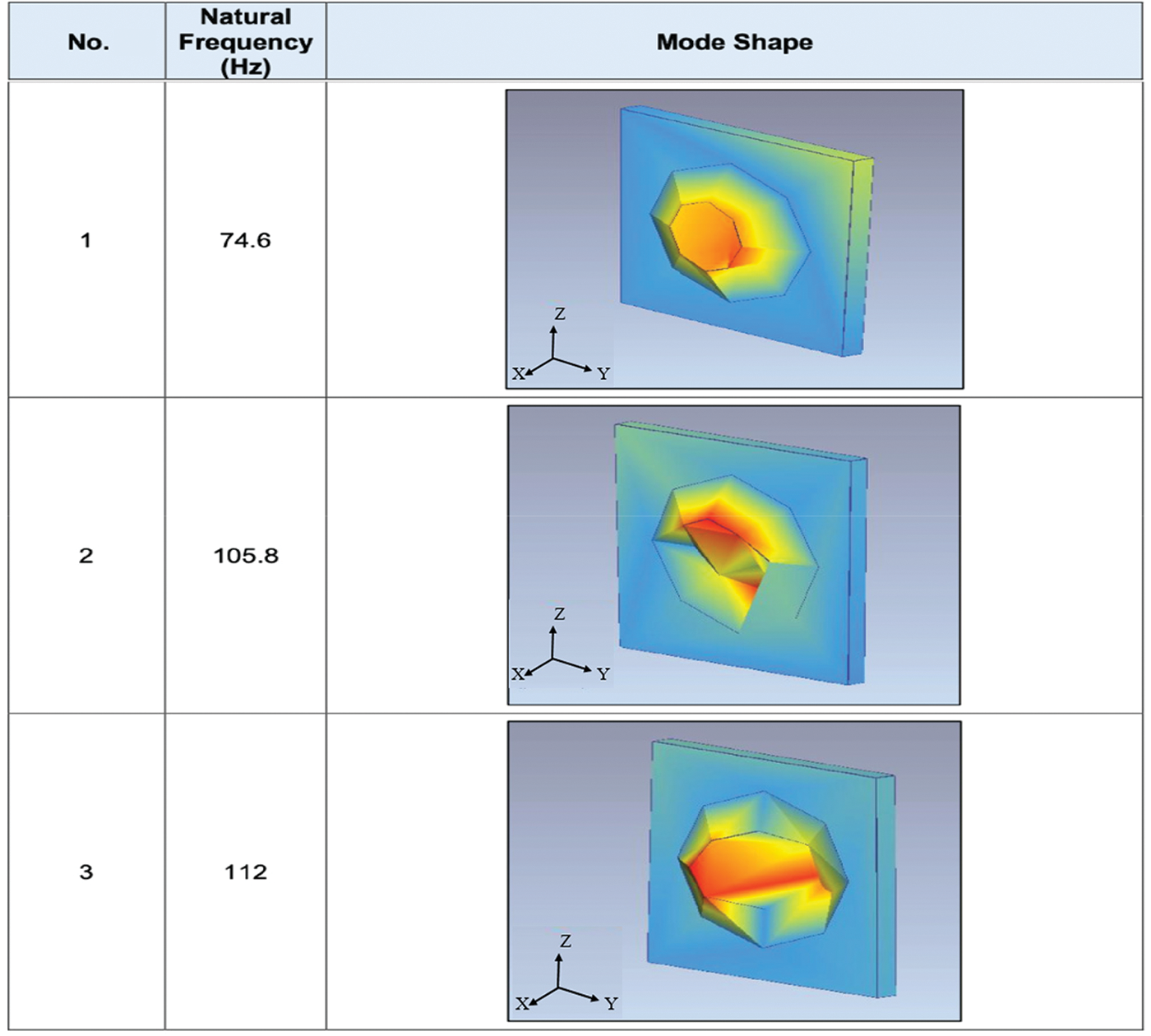
Figure 12: The mode shape of the endplate (NDE) at particular natural frequency
Vibration measurement and operating modal analysis (OMA) have been conducted on a motor-compressor system. High vibration at 112 Hz was found as the result of structural resonance confirmed by the measurement data from OMA. The mode shape at 112 Hz depicted a torsional behavior of the motor shaft followed by the “wobbling” motion of the motor. This vibration excitation also caused a bulging effect on the endplate of the motor. The uneven load in the compressor is believed to amplify the pulsating components where 18X coincided with the natural frequency of the structure assembly at 112 Hz. The strong torsional vibration movement described in the finding is caused by dynamic load from the reciprocating compressor. Fluctuation load from the compressor induces fluctuation movement of the crankshaft causing twisting movement and deflecting the system at a frequency of 112 Hz. From the OMA perspective, if there is an indication of torsional movement with a clear resonance frequency, then it can be concluded there is an existence of torsional mode of the motor can be further confirmed by the measurement of a torsional vibration analysis using torsional laser vibrometer.
Acknowledgement: The authors gratefully acknowledge the support received from Engineering Department, Malaysia Refining Company (Petronas) and Centre for Advanced Research on Energy (CARe) and the Universiti Teknikal Malaysia Melaka, Malacca, Malaysia.
Funding Statement: The authors received no specific funding for this study.
Author Contributions: Conceptualization, R.M.D.; methodology, M.F.Y., M.F.S. and R.M.D.; software, M.F.Y.; validation, Z.Y., M.F.Y. and R.M.D.; formal analysis, A.P.; investigation, Z.Y. and M.F.S.; data curation, A.P.; writing—original draft preparation, M.F.Y.; writing—review and editing, R.M.D. and A.P. All authors have read and agreed to the published version of the manuscript.
Availability of Data and Materials: Not applicable.
Conflicts of Interest: The authors declare that they have no conflicts of interest to report regarding the present study.
References
1. Scheffer, C., Girdhar, P. (2004). Practical machinery vibration analysis and predictive maintenance. Oxford: Elsevier. [Google Scholar]
2. Amirudin, A. A. A., Kamarumtham, K. I., Haripriyono, A. A., Yunus, A. A. R., Suheimy, N. A. S. (2022). A review of the dynamic analysis of axial vibrations in marine propulsion shafting system due to propeller excitation. ASEAN Engineering Journal, 12(2), 19–27. [Google Scholar]
3. Liang, X., Wen, Y., Shu, G., Wang, Y., Wang, X. (2014). Axial vibration source identification of engine crankshaft based on auto-regressive and moving average model and analytic hierarchy process method. Journal of Vibration and Control, 20(8), 1185–1198. [Google Scholar]
4. Long, Y., Ye, Y. (2021). Axial vibration analysis of thrust support of vertical hydrogenerator unit. E3S Web of Conferences, 276, 1–4. [Google Scholar]
5. Arifin, A. (2018). Vibration analysis of unbalance on axial fan engine 5.5 kw. International Journal of Advanced Materials Science, 5, 273–280. [Google Scholar]
6. Medoued, A., Mordjaoui, M., Soufi, Y., Sayad, D. (2016). Induction machine bearing fault diagnosis based on the axial vibration analytic signal. International Journal of Hydrogen Energy, 41(29), 12688–12695. [Google Scholar]
7. Mohammadi, Y., Ahmadi, K. (2019). Effect of axial vibrations on regenerative chatter in robotic milling. Procedia CIRP, 82, 503–508. [Google Scholar]
8. Fikre, E. B., Lenz, J. (2015). Torsional vibration problem in reciprocating compressor—case study. SIRM 2015—11th International Conference on Vibrations in Rotating Machines, pp. 23–25. Magdeburg, Germany. [Google Scholar]
9. Zhao, J., Wang, S. (2014). Analysis for fatigue failure causes on a large-scale reciprocating compressor vibration by torsional vibration. Procedia Engineering, 74, 170–174. [Google Scholar]
10. Kacani, V. (2017). Vibration analysis in reciprocating compressors. IOP Conference Series: Materials Science and Engineering, 232, 012016. [Google Scholar]
11. International Organization for Standardization (1995). Mechanical vibration. Evaluation of machine vibration by measurement on non-rotating parts. Part 6: Reciprocating machines with power rating above 100 kW. ISO 10816-6:1995(en). https://www.iso.org/obp/ui/en/#iso:std:iso:10816:-6:ed-1:v1:en (accessed on 20/09/2023) [Google Scholar]
12. Brincker, R., Ventura, C. (2015). Introduction to operational modal analysis. UK: John Wiley & Sons. [Google Scholar]
Cite This Article
 Copyright © 2023 The Author(s). Published by Tech Science Press.
This work is licensed under a Creative Commons Attribution 4.0 International License , which permits unrestricted use, distribution, and reproduction in any medium, provided the original work is properly cited.
 Downloads
 Citation Tools