
 Submit a Paper
 Open Access
ARTICLE

Enhancing Sound Absorption in Micro-Perforated Panel and Porous Material Composite in Low Frequencies: A Numerical Study Using FEM
Department of Occupational Health Engineering, School of Public Health, Tehran University of Medical Sciences, Tehran, Iran
* Corresponding Author: Mohammad Javad SheikhMozafari. Email: Array
Sound & Vibration 2024, 58, 81-100. https://doi.org/10.32604/sv.2024.048897
Received 21 December 2023; Accepted 11 January 2024; Issue published 27 February 2024
 View Full Text
 Download PDF
Abstract
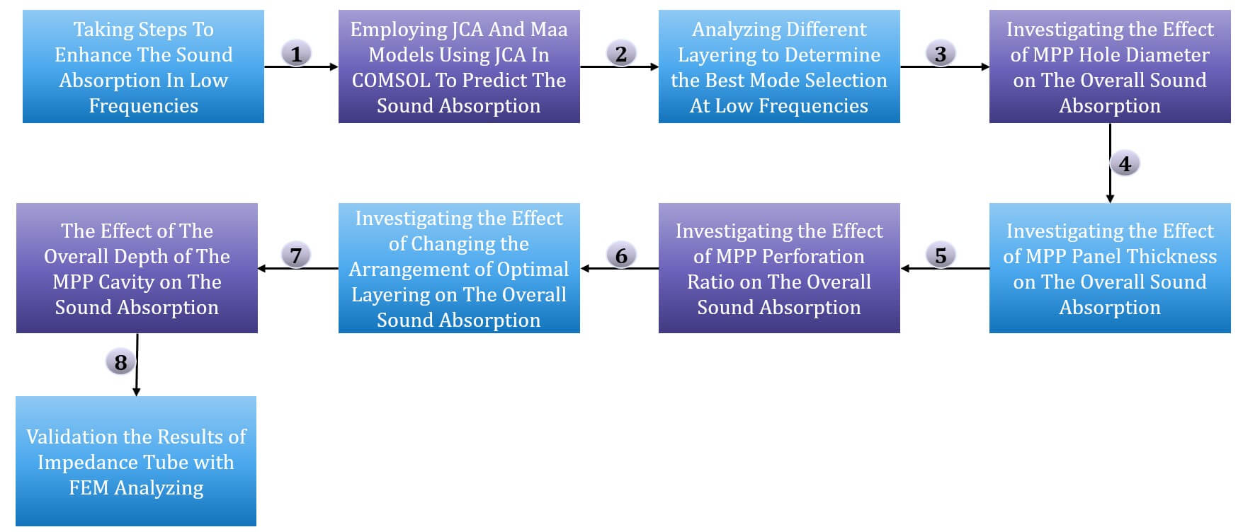
Mitigating low-frequency noise poses a significant challenge for acoustic engineers, due to their long wavelength, with conventional porous sound absorbers showing limitations in attenuating such noise. An effective strategy involves combining porous materials with micro-perforated plates (MPP) to address this issue. Given the significant impact of structural variables like panel thickness, hole diameter, and air gap on the acoustic characteristics of MPP, achieving the optimal condition demands numerous sample iterations. The impedance tube’s considerable expense for sound absorption measurement and the substantial cost involved in fabricating each sample using a 3D printer underscore the advantage of utilizing simulation methods to attain the optimal state. This study focuses on optimizing low-frequency enhancement by investigating key parameters. Using the Finite Element Numerical Method (FEM) in COMSOL software, a composite panel was constructed comprising date palm fiber layers, an intervening air layer, and MPP. The study explored the arrangement of these layers and the impact of parameters like hole diameter, plate thickness, and perforation ratio on acoustic behavior. The selected optimal parameter at each stage was consistently maintained for subsequent steps. Results revealed that layer arrangement significantly influenced acoustic characteristics. Placing the MPP layer before the porous material yielded superior low-frequency performance. Optimizing low-frequency behavior involved reducing hole diameter and perforation ratio while increasing plate thickness. Elevating the porous material’s thickness relative to the air layer behind the MPP enhanced absorption peak and resonance frequency. In conclusion, halving the porous layer’s thickness while incorporating an air layer and single MPP proved more effective than using a thick porous material. This approach not only reduces costs and space requirements but also enhances low-frequency performance. The study highlights the precision of numerical methods like FEM, reducing the need for resource-intensive direct methods and associated laboratory expenses.Graphic Abstract
Keywords
Nomenclature
| MPP | Micro-perforated panel |
| FEM | Finite element method |
| | Porosity |
| | Air flow resistivity |
| | Tortuosity |
| Λ | Viscous characteristic length |
| Λ ́ | Thermal characteristic length |
| JCA | Johnson-Champoux-Allard |
In today’s era of modernization and urban development, noise pollution has emerged as a fundamental challenge for both developed and developing nations, significantly impacting human health and productivity [1]. The repercussions of noise pollution encompass a range of detrimental effects, including heightened stress levels, cognitive impairments, sleep disturbances, cardiovascular disorders, Preeclampsia, restlessness, and elevated blood pressure [2]. A prominent solution for mitigating noise in the environment involves the utilization of sound absorbers. The field of acoustic absorbers comprises three principal categories: porous absorbers, Helmholtz absorbers, and panel or membrane absorbers [3]. Among these, porous absorbers stand out due to their notable absorption efficiency and cost-effectiveness relative to the other options [4]. Particularly regarding porous absorbers, fiber-based materials hold a significant position and can be categorized into natural and synthetic fibers [5]. Historically, synthetic fibers have dominated the sound absorption landscape, boasting nearly complete absorption at high frequencies (2000 Hz and above) and continuing to be widely employed. However, recent years have witnessed a shift in focus attributed to growing environmental and health concerns associated with the production and use of synthetic fibers [6]. Consequently, researchers are increasingly exploring the potential of natural, less ecologically disruptive fiber materials as a more sustainable alternative. To date, natural fibers have been extensively examined as sound absorbers, with numerous studies highlighting their commendable attributes, including good sound absorption capabilities, ease of fabrication, lightweight nature, eco-friendliness, and human health safety [7–10]. Despite these advantageous characteristics of porous absorbers, a notable limitation prevails in their efficacy at lower frequencies, particularly below 1000 Hz [11]. The significance of reducing noise in low frequencies, particularly below 1000 Hz, stems from various reasons. Firstly, human speech frequencies commonly range between 500 to 1000 Hz, and human hearing sensitivity is most acute around the 1000 Hz frequency. Consequently, discussions related to noise annoyance and the negative psychological impacts of noise on individuals often occur within this frequency range, prevalent in many office settings. Moreover, low-frequency noise is pervasive in industrial and environmental surroundings, originating from devices like compressors, fans, ventilation systems, vehicles, aircraft, and others [12]. These instances underscore the criticality of noise control measures, especially in low-frequency domains. Controlling low-frequency noise poses challenges due to the lengthy wavelengths associated with such frequencies. Porous materials employed as absorbers require a thickness comparable to the wavelength to maximize efficiency at lower frequencies [13]. However, this requirement imposes limitations on their use, primarily due to space constraints and escalated production costs. Moreover, the applicability of fibrous porous materials alone encounters restrictions in sterile settings like hospitals, food industries, and restaurants. The use of fibers is limited due to the potential dispersion of fiber particles into the environment. Additionally, fibrous materials present health hazards, causing skin and respiratory issues due to their fibrous composition, thus requiring careful consideration. Further compounding porous absorbers drawbacks, fibrous porous materials are susceptible to fire, wind, moisture, and mechanical stresses [14]. This vulnerability impedes effective control of low-frequency noise in indoor spaces, a task challenging to achieve using porous materials alone. In response, several strategies have been proposed in research to enhance low-frequency absorption. Among these, augmenting absorber thickness and introducing an intervening air layer behind the material have been explored [15]. However, these solutions often clash with the λ/4 rule, wherein λ represents the wavelength of noise at a given frequency. The rule stipulates that a porous absorber should ideally possess a λ/4 thickness for optimal performance [16]. For instance, at a frequency of 300 Hz, an absorber necessitates an impractical thickness of approximately 29 cm to attain optimal efficiency—an unfeasible prospect, both economically and spatially within an environment.
To enhance absorption at lower frequencies, researchers have turned their focus to the utilization of micro-perforated panels (MPP), heralded as a new generation of absorbers [17]. MPP constitutes a solid plate punctuated with numerous sub-millimeter-diameter apertures and is positioned alongside an air gap. The absorption mechanism of MPP primarily relies on sound traversal through these minuscule openings, inducing viscous loss and consequently converting sound energy into thermal energy [18]. Notably, MPP boasts a remarkable advantage in its potential for exceedingly high absorption coefficients when the incident sound frequency aligns with the panel’s resonance frequency [15]. This innovation extends further advantages, including robust durability, recyclability, fire resistance, wind and humidity resilience, cost-effectiveness, ease of design, and straightforward installation [14]. Moreover, MPP distinguishes itself by its absence of fibrous constituents, enabling its application in environments where fiber deployment is prohibited, such as hospital settings, clean rooms, and food industries. This consideration arises from the potential release of fibrous particles into the surroundings over time, leading to environmental contamination and respiratory concerns for occupants [14].
While micro-perforated panels (MPP) have been heralded as the next-generation solution, replacing traditional fiber-based absorbers, their absorption mechanism, reliant on Helmholtz resonance, tends to yield weaker performance in terms of both absorption efficiency and bandwidth [18]. Existing research primarily focuses on broadening the absorption bandwidth of MPPs, employing strategies such as altering air cavity dimensions, utilizing dual parallel or series MPP plates, and modifying structural parameters, among others [15]. Another avenue explored to enhance MPP absorber bandwidth involves the incorporation of porous materials within the rear air cavity. This concept has been addressed by Sakagami, and Hashemi, too [15,18]. The synergistic implementation of MPP and porous absorbers not only augments MPP absorber bandwidth but also enhances the absorption coefficient of porous materials at lower frequencies. Furthermore, this combination bolsters the overall robustness and resilience of the fiber-based absorber against factors like moisture, wind, fire, and mechanical impacts, as evidenced in research by Sakagami, Li, Hashemi, and other scholars [15,18].
The assessment of material absorption is conducted through the utilization of the sound absorption coefficient (
In recent years, there has been a notable surge in the investigation of natural fibers as potential sound absorbers. Date palm fibers, among the porous fibrous materials, have gained prominence in numerous recent studies as a viable substitute for synthetic fibers, particularly in terms of sound absorption coefficients within middle and high-frequency ranges [19–22]. It is noteworthy that Iran ranks as the second-largest producer of date palms worldwide, trailing only Egypt. Paradoxically, approximately 200 thousand tons of potentially industrial-grade materials are discarded or incinerated annually due to improper waste management practices. Consequently, given the extensive cultivation of this resource across Iran and other global regions, date palm fibers emerge as an auspicious resource for sustainable composite production and sound absorption [23]. Given the predominant focus on MPP absorbers and synthetic fibers in global research endeavors and the persistent challenges posed by noise control, especially in low and medium frequencies within occupational settings, a comprehensive understanding of the phenomenon remains elusive. On the other hand, Given the significant impact of structural variables like panel thickness, hole diameter, and air gap on the acoustic characteristics of MPP, achieving the optimal condition demands numerous sample fabrication. The impedance tube’s considerable expense for sound absorption measurement and the substantial cost involved in fabricating each sample using a 3D printer underscore the advantage of utilizing simulation methods to attain the optimal state. Accordingly, this study aims to explore the efficacy of a simulated composite panel encompassing natural date palm fibers, MPP, and an air layer, particularly within the frequency range below 2000 Hz. The simulation employed the Finite Element Numerical Method (FEM) through COMSOL software version 6.3. Insight into the characteristics of date palm natural fibers is sourced from Taban et al.’s research [19].
The concept of Micro-Perforated Panel (MPP) acoustic impedance was initially introduced by Maa [15]. As elucidated in Maa’s research, the computation of acoustic impedance follows the subsequent equations:
And finally, the absorption coefficient is calculated using the following equation:
Within these equations, the variables r and m denote resistance and reactance, correspondingly. The parameter
As it is clear, acoustic impedance encompasses both real and imaginary components. The real component is recognized as resistance, while the imaginary part is called reactance. Resistance signifies the dissipation of viscosity due to the passage of air through the perforations in the MPP, leading to resultant friction. Conversely, reactance pertains to the mass of air traversing through these apertures.
2.2 Acoustic Impedance of Date Palm Fiber
To compute the acoustic impedance of porous materials, experimental-analytical models incorporating characteristic impedance and propagation constant factors can be employed. Notably, Delany-Bazley (DB) and Miki models, alongside the Johnson-Champoux-Allard (JCA) model, fall within this category [23]. In contrast to the JCA model, both DB and Miki models utilize solely the airflow resistivity parameter for acoustic impedance calculation. The JCA model, however, employs five parameters for this calculation. Consequently, the DB and Miki models offer relative ease of use due to their singular parameter nature, although they exhibit lower accuracy compared to the JCA model. In light of this, the present study adopts the JCA model to ascertain the acoustic impedance of the porous material.
JCA Model: In 1992, Champeaux and Allard introduced a phenomenological mathematical framework for anticipating sound propagation within porous materials [15]. This model relies on two key parameters, namely the bulk modulus and equivalent density, which are computed using the subsequent expressions:
The physical parameters used in these equations include
The following equations can be used to calculate the acoustic surface impedance of the porous material (
To simulate the acoustic characteristics of the devised composite, the data pertinent to the five parameters of natural date palm fibers required for employment in the Finite Element Method (FEM) has been derived from the research conducted by Taban et al. [19].
2.3 Comparison of the Acoustic Behavior of Date Palm Fibers with Other Natural Fibers
As mentioned before, the selection of date palm fibers for this study was motivated by various reasons. Primarily, Iran’s position as the second-largest producer of date palm groves globally and the significant yearly waste generated from these groves prompted the consideration of this abundant yet underutilized resource. Additionally, date palm fibers possess distinctive acoustic properties that distinguish them from other natural fibers. Notably, research by Taban et al. highlighted the exceptional acoustic absorption capabilities of date palm fibers. For instance, at a thickness of 4 cm and a density of 200 kg/m³, these fibers exhibit an absorption coefficient of 0.9 at a frequency of 2000 Hz [19]. Comparatively, other fibers, such as hemp (6 cm thickness, absorption coefficient of 0.9), coconut (3 cm thickness, absorption coefficient of 0.79), and cork (3 cm thickness, absorption coefficient of 0.86) [24], demonstrate similar or slightly inferior acoustic performance. These findings emphasize the promising acoustic behavior of date palm fibers in densities and thicknesses that are comparable to other natural and recyclable fibers.
2.4 Utilizing the Finite Element Method (FEM) for Simulation
Various techniques, including analytical methods like transfer matrices and numerical methods like Finite Element Method (FEM) and Boundary Element Method (BEM), are available for calculating the overall impedance of MPP-porous material composites. Among these numerical methods, the Finite Element Method holds widespread application [15]. The simulation in this study was executed using COMSOL software version 6.1, which employs FEM. Within the COMSOL software framework, the acoustic wave is modeled through acoustic pressure within a specified domain, and its behavior is determined by solving the Helmholtz equation:
In the equation, p is sound pressure
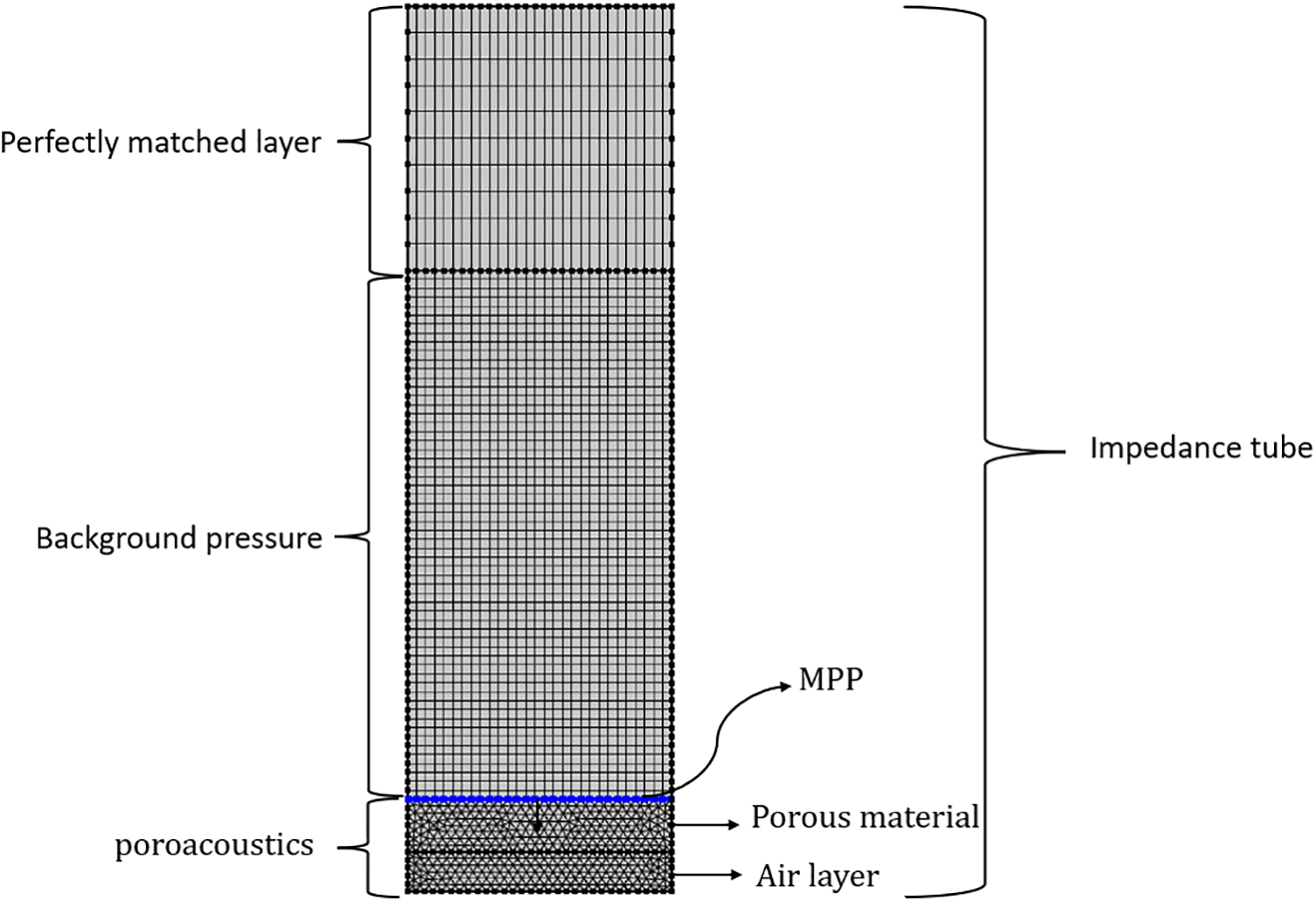
Figure 1: Impedance tube simulated in COMSOL using FEM
In this part, there are different models to investigate sound wave propagation into the porous material, such as Delaney-Bazley- Miki, JCA, etc. To obtain more accurate results, the maximum mesh size of the model was chosen to be one-sixth of the minimum wavelength. Since it has been mentioned in most of the studies that in the combined use of porous material and MPP, absorption at frequencies less than 3000 is suitable [15,26], and on the other hand, this study aims to improve the acoustic behavior and increase the bandwidth of porous absorbers and MPP in low frequencies. as a result, the frequency range of 63 to 2000 Hz was investigated for this composite.
2.5 Validation of FEM Modeling Results
To ensure that the results obtained from FEM are consistent with the laboratory results and direct measurement of the impedance tube, the results of the impedance tube were compared with FEM simulation.
The initial phase of the study delved into exploring the acoustic attributes of the porous material across varying thicknesses and densities, as guided by the research conducted by Taban et al. Among the array of thicknesses and densities investigated, it emerged that fibers measuring 40 mm in thickness and possessing a density of
Given that the acoustic characteristics of the composite panel, comprising both porous material and MPP, are influenced by a multitude of effective parameters, an in-depth exploration of these influences was undertaken. This examination encompassed the arrangement and positioning of each layer, aiming to discern the configuration that yields superior acoustic performance at lower frequencies. Consequently, to determine the most effective combination of porous material, air layer, and MPP for enhanced low-frequency absorption, four distinct modes were subjected to rigorous testing, ultimately leading to the selection of the optimal mode. These four configurations are visually depicted in Fig. 2.
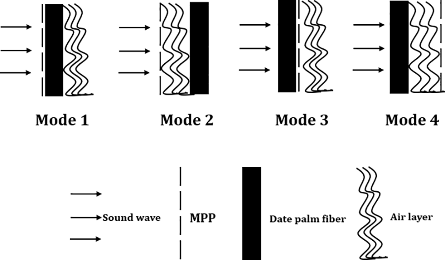
Figure 2: Different layouts and layering used to determine the best mode selection at low frequencies
Following the selection of the most optimal mode for low frequencies, an examination was conducted to explore the impact of altering the parameters of the MPP on the composite’s acoustic performance within the low-frequency spectrum. To achieve this, three key parameters were investigated: hole diameter, plate thickness, and MPP porosity percentage. However, within each iteration, two parameters remained fixed while the target parameter was modified. The assessment of these parameters took place in the following configurations:
Hole diameter (mm): 0.3, 0.5, 0.7, 0.9 and 1.
Plate thickness (mm): 0.5, 1, 1.5, 2 and 2.5.
Perforation ratio (%): 6, 8, 10, 15 and 20.
Subsequently, in the subsequent phase, a meticulous examination was conducted to ascertain whether alterations in the arrangement of the chosen mode, selected from modes 1 to 4, had any influence on the acoustic performance of the composite. To explore this, within mode 1, the thickness of both the porous material and the air layer was reduced by half. Therefore, the sequential order of layer placement from uppermost to lowermost was as follows: MPP layer, 20 mm of porous material, 15 mm of air layer, followed by another 20 mm of porous material and a concluding 15 mm of air layer.
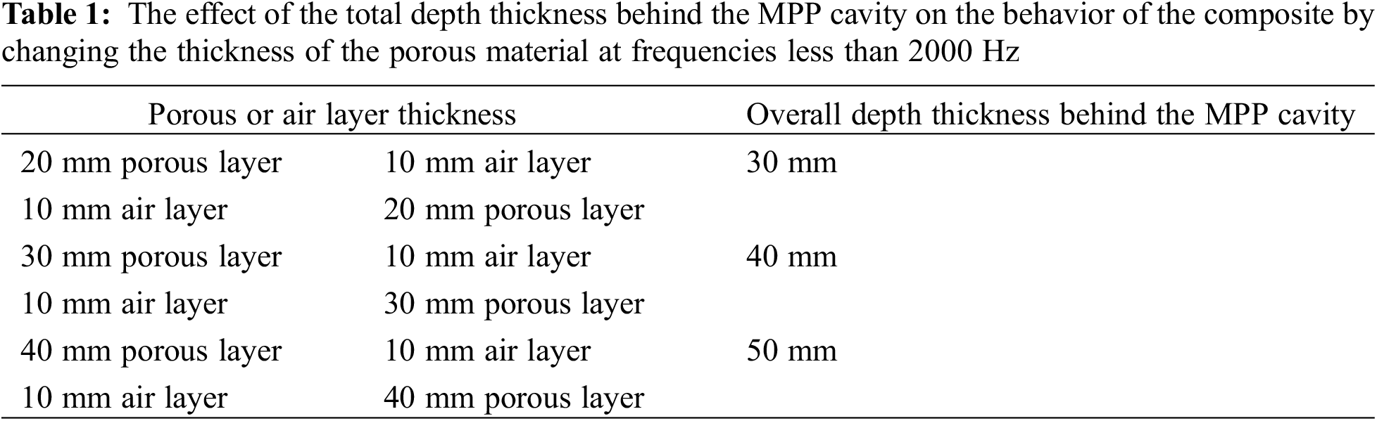
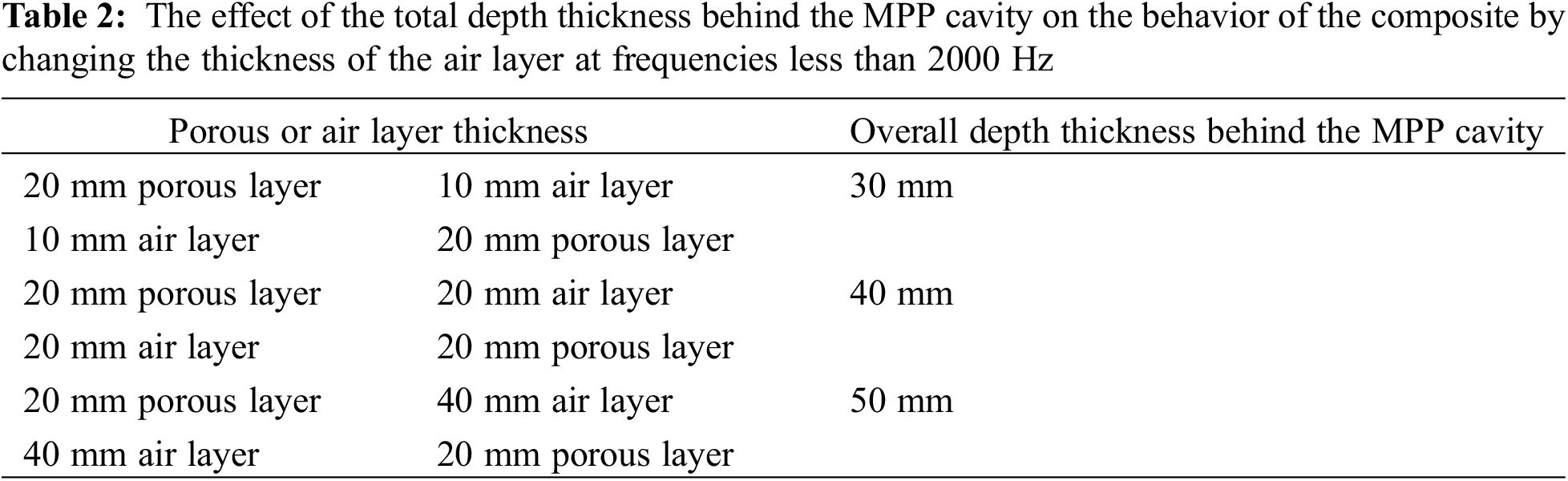
Given the frequent necessity to utilize mode 1 or 2 in various scenarios, including enhancing the mechanical robustness of the porous absorber, fortifying its resilience against moisture, wind, and fire, as well as averting the emission of fiber absorbent particles into the surroundings, an exploration was undertaken to ascertain whether the total depth of the chamber behind the MPP impacts its acoustic performance. Consequently, based on the superior behavior exhibited by either mode 1 or 2 at frequencies below 2000 Hz, the modes outlined in Tables 1 and 2were evaluated.
3.1 Comparison of the Acoustic Behavior of Porous Material with a Thickness of 10 mm and MPP
As depicted in Fig. 3 and expounded upon in the introduction, it is evident that porous fibrous materials exhibit commendable performance in higher frequencies, yet their efficacy diminishes considerably in lower frequencies. Enhancing the absorption coefficient at lower frequencies necessitates augmenting thickness, air gap, and density. However, adhering to the λ/4 rule for optimal low-frequency absorption would demand impractically substantial dimensions of porous material and air gap. Consequently, alternative solutions need to be explored. Furthermore, porous fiber materials entail other drawbacks, including limited mechanical resilience, susceptibility to airflow, moisture, and fire, along with the potential release of fiber particles into the environment, thereby contributing to environmental contamination and human discomfort. An alternative approach to address these challenges concurrently involves the substitution of porous fiber materials with MPP absorbers.
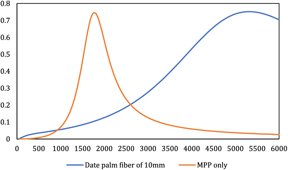
Figure 3: Comparison of the behavior of the porous material in the thickness of 10 mm with an MPP layer
Conversely, an MPP layer devoid of a porous material displays enhanced behavior within intermediate frequencies. Nevertheless, its bandwidth remains severely restricted and will not expand unless alterations are introduced to its structure and composition. Consequently, an additional strategy emerges to amplify low-frequency absorption for fiber-based absorbers while broadening the bandwidth for MPP absorbers. This strategy also aims to ameliorate certain issues, enhance the overall durability of fiber absorbers, and forestall the dispersion of particles into the environment. This entails the concurrent application of both porous fiber materials and MPP absorbers. However, to achieve the intended outcomes and effectively govern the desired frequency spectrum, meticulous attention must be directed towards the factors influencing the performance of MPP and fiber absorbers.
Consequently, to achieve effective absorption through the porous material layer at lower frequencies and simultaneously enhance the MPP’s bandwidth absorption, the subsequent stages incorporated a porous material thickness of 40 mm along with an air layer of 30 mm.
3.2 Assessment of Layering and Diverse Configurations on Composite Performance at Frequencies below 2000 Hz
Fig. 4 presents a comparative analysis of the acoustic performance among various configurations of distinct layers, aiming to identify the mode exhibiting superior acoustic behavior at frequencies below 2000 Hz. Additionally, all four modes have been juxtaposed against a 4 cm thickness of porous material to ascertain the optimal mode for enhanced behavior at lower frequencies. The study encompasses four distinct configurations, as illustrated in Fig. 2.
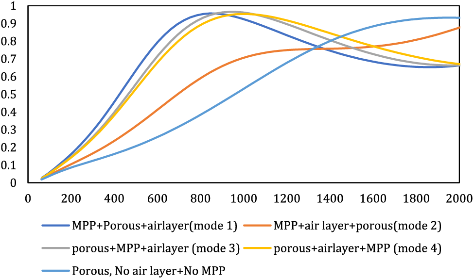
Figure 4: Comparison of different configurations of acoustic behavior with porous material without MPP
The primary objective of this study was to identify the optimal mode for enhancing absorption at frequencies below 2000 Hz. As depicted in Fig. 4, the porous material exhibits limited absorption at frequencies below 1000 Hz. However, with the incorporation of MPP, a substantial enhancement in the panel’s performance at low frequencies becomes evident. For instance, while the porous material demonstrates an absorption coefficient of 0.5 at a frequency of 1000 Hz, the addition of MPP elevates this coefficient to a minimum of 0.95 for the same frequency. The amplification of MPP bandwidth through the introduction of porous material can be attributed to a dual damping effect, resulting in an expanded bandwidth.
Among the four investigated modes, mode 1 outperforms the others in low frequencies. The mean absorption coefficients in modes 1, 2, and 3 at frequencies below 2000 Hz hover around 0.67, yet mode 1 displays superior performance at frequencies below 1000 Hz. For instance, at a frequency of 573 Hz, mode 1 records an average absorption coefficient of 0.75, whereas modes 2 and 3 exhibit coefficients of 0.67 and 0.63, respectively. Corroborating studies by Hamdan and Hashemi underscored that the introduction of porous material behind the MPP augments absorption at low frequencies [15,18]. However, the overall average absorption coefficient of the composite in modes 3 and 4 slightly surpasses that of mode 1. Mode 1, the optimal choice for frequencies under 2000 Hz, exhibited an average absorption coefficient of 0.74 within the 63 to 6300 Hz range, while, modes 3 and 4 showcased an average absorption coefficient of 0.8. It is notable if the study’s goal was to enhance the overall absorption coefficient and broaden bandwidth towards higher frequencies, modes 3 and 4, with the porous material preceding the MPP, proved superior. Li et al.’s study highlighted that positioning the porous material at the forefront of the MPP led to higher absorption rates at high frequencies compared to low frequencies [27]. This trend can be attributed to an impedance-matching effect generated by this configuration at higher frequencies [18]. Regarding sound absorber composites, which typically consist of multiple layers or materials, like the present composite, achieving an impedance-matching effect can significantly impact their acoustic performance. When two adjacent layers within the composite have similar or matched acoustic impedance values, it minimizes the reflection of sound waves at the interface between these layers. This reduction in reflection helps in maximizing the transfer of sound energy into the absorptive material, thereby improving overall absorption efficiency. The impedance-matching effect is essential in optimizing the performance of sound absorber composites, as it minimizes the loss of sound energy due to reflections and allows for better utilization of the absorptive material’s properties. By carefully selecting and arranging materials with compatible acoustic impedance values, engineers can design composites that effectively absorb or attenuate sound across a desired frequency range.
In the case of composites comprising porous materials and resonators like MPP, the sequence of layers significantly influences the composite’s behavior. Each layer’s positioning dictates its predominant impact on the composite’s behavior. Given that the MPP takes precedence in arrangement 1, the composite’s overall behavior remains influenced by the MPP, resulting in higher absorption at lower frequencies than at higher frequencies. Conversely, positioning the porous material ahead of the MPP (modes 3 and 4) alters the composite’s behavior, contributing to slightly higher absorption at higher frequencies than at lower frequencies. The reason behind the higher absorption in high frequencies in mode 2, despite the MPP being situated in the foremost position, can be attributed to the concurrent placement of the MPP and the air layer ahead of the porous material. This configuration has led to an additional void space preceding the porous material. Consequently, this setup has amplified internal reflections within the composite, augmenting resonance and decreasing sound absorption at specific frequencies due to increased reflection. At the same time, certain frequencies experience cancellation owing to phase differences, resulting in heightened absorption in those frequencies. This interplay has led to a reduction in absorption at lower frequencies in this scenario.
Consequently, mode 1 was identified as the optimal configuration. Subsequently, the impact of modifying MPP parameters on the overall composite behavior was examined within mode 1. In conclusion, the interplay of porous material, air layer, and MPP arrangement significantly impacts the overall acoustic performance of the composite. For a focus on heightened bandwidth in either high or low frequencies, the recommended order is porous material, MPP, and air layer, or MPP, porous material, and air layer. Thus, this study’s findings align harmoniously with prior research outcomes [28].
A noteworthy point to address is the reason behind the nearly disappearing resonance absorption and the broadening of the bandwidth when incorporating a porous material into the air gap behind the MPP. In typical perforated panels with larger perforations, the acoustic resistance within the perforation tends to be quite low. As a solution to elevate resistance and enhance sound absorption, it is a common practice to position a porous layer behind the perforated panel. The introduction of porous material within the space behind the MPP augments the impedance’s resistance. Consequently, this contributes to broadening the bandwidth by establishing dual damping mechanisms [29].
3.3 The Effect of MPP Hole Diameter on the Overall Performance of the Composite
The hole diameter stands as a pivotal parameter exerting a substantial influence on MPP behavior. To achieve the intended acoustic response, the precise selection of hole dimensions becomes imperative. In pursuit of this objective, an exploration of hole diameter variation was conducted while maintaining the other parameters of the mode 1 constant. Fig. 5 offers a comprehensive overview of the composite’s behavior across the alteration of hole diameter, focusing on frequencies below 2000 Hz.
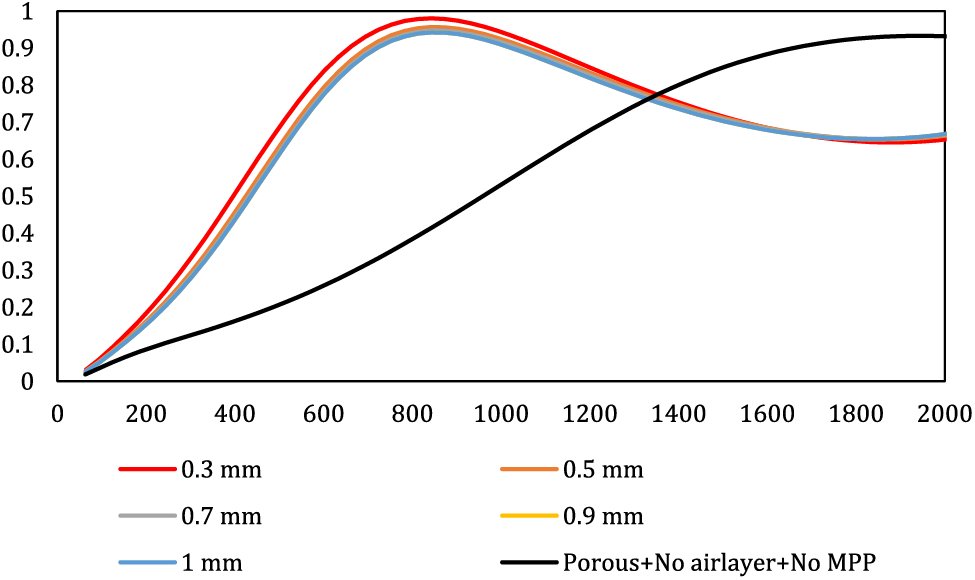
Figure 5: Effect of hole diameter on the overall behavior of the composite
As illustrated in Fig. 5, decreasing the hole diameter leads to an increase in both the absorption peak and the composite’s performance enhancement at lower frequencies. This indicates that a smaller hole diameter corresponds to a higher resonance peak. Conversely, widening the hole diameter results in a reduction of the absorption coefficient and a weakening of the resonance peak. Notably, the porous material’s performance at low frequencies is modest when devoid of MPP. However, the introduction of MPP and the judicious selection of hole diameter can significantly enhance the panel’s behavior at these lower frequencies. Throughout this study, the alteration of hole diameter solely influenced the resonance peak, leaving the resonance frequency unaffected. Irrespective of the diameter, the resonance frequency remained constant at 843 Hz. In essence, the hole diameter seems to primarily impact the magnitude of the resonance peak without altering the acoustic behavior of the composite. This stability implies that the material’s inherent structural characteristics or the fundamental dimensions and composition of the composite material—beyond just the size of the perforations—play a dominant role in determining this particular resonance frequency. Also, it implies that the impedance modifications caused by changes in hole diameter do not directly influence the underlying fundamental resonance behavior determined by other intrinsic characteristics of the composite material. The reason behind the increased absorption peak with reduced hole diameter lies in the slight augmentation of acoustic resistance. Consequently, as the airflow passes through the smaller MPP holes, the viscosity-induced losses escalate, contributing to a higher absorption coefficient. This phenomenon is also addressed in Hashemi et al.’s research [15]. Additionally, Li et al.’s study concurred with these findings by highlighting that diminishing the hole diameter expands the bandwidth [30]. Hamdan’s investigation similarly notes that the utilization of micrometer-scale holes improves sound absorption performance [18].
It should be mentioned that given the circumstances of this study, it is apparent that opting for excessively small hole diameters is not cost-effective. The challenges in producing these minute holes, coupled with increased expenses using methods like 3D printers or CNC, suggest that maybe maintaining an average hole size could offer a viable solution to address this issue.
3.4 The Effect of MPP Panel Thickness on the Overall Performance of the Composite
To explore the impact of panel thickness, the remaining parameters were held constant while varying the panel thickness parameter. The outcomes of this investigation into the influence of panel thickness on the composite’s overall behavior are depicted in Fig. 6.
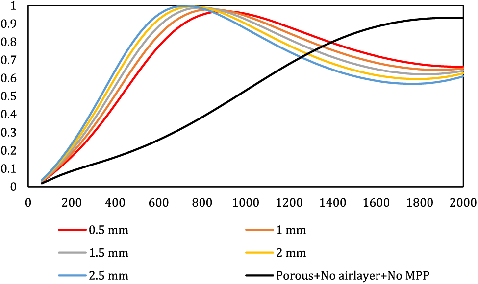
Figure 6: Effect of panel thickness on the overall behavior of the composite
As depicted in Fig. 6, augmenting the panel thickness is associated with an elevation in the resonance peak and heightened absorption at low frequencies, albeit at the cost of a narrower overall bandwidth. Conversely, reducing panel thickness leads to a diminished resonance peak and a smoother graph. Notably, an escalation in panel thickness corresponds to an increase in absorption coefficients at low frequencies, while a reduction in panel thickness results in heightened absorption coefficients at high frequencies. For instance, at a frequency of 500 Hz, a composite with a thickness of 2.5 exhibits an absorption coefficient of 0.85, whereas a thickness of 0.5 yields an absorption coefficient of 0.64. This effect can be attributed to the heightened stiffness and mass of the panel, which in turn leads to an increase in structural resonances. Unlike the hole diameter, which predominantly influences the resonance peak, the panel thickness appears to play a role in determining the bandwidth. Consequently, as the panel thickness increases, the bandwidth contracts, causing the absorption peak to shift towards lower frequencies. The total impedance formula of MPP indicates that as the panel thickness increases, the resistance within the impedance also increases. This implies that thicker panels contain a larger total mass of air within the perforations compared to thinner panels, while the stiffness of the resonator system remains constant due to identical air cavity depths. Consequently, the resonant frequency associated with the peak frequency decreases [31]. These findings echo those of prior studies [18,32], thereby reinforcing the consistency and validity of the present study’s outcomes.
3.5 The Effect of Perforation Ratio on the Overall Performance of the Composite
To assess the impact of the perforation ratio, this parameter was treated as a variable while keeping the remaining factors constant. The outcomes of the investigation into the perforation ratio’s effect are presented in Fig. 7.
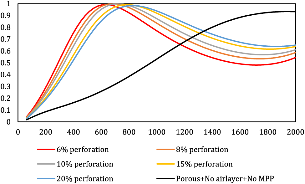
Figure 7: The effect of MPP perforation ratio on the overall behavior of the composite
Illustrated in Fig. 7, an augmentation in the perforation ratio of the panel induces a shift in the resonance frequency towards higher frequencies, concomitantly accentuating absorption at those higher frequencies. Conversely, a reduction in the perforation ratio leads to an increase in the absorption peak, causing it to transition towards lower frequencies. To elucidate, at a frequency of 500 Hz, panels with perforation ratios of 6 and 20 exhibit absorption coefficients of approximately 0.9 and 0.7, respectively. Interestingly, the reduction in the percentage of perforation enhances absorption at lower frequencies, whereas an augmentation in the perforation ratio improves absorption at higher frequencies. It is noteworthy that this manipulation primarily affects the bandwidth rather than altering the peak amplitude. Thus, the study underscores the critical importance of selecting an appropriate perforation ratio to attain the desired bandwidth and optimal absorption range. In a broader context, assuming constant MPP plate thickness and cavity depth, the perforation ratio manifests a direct relationship with the resonance frequency. An increase in the perforation ratio causes a decrease in the acoustic mass reactance, Conversely, reducing the perforation percentage results in an elevation of impedance resistance. This increased resistance prompts higher viscosity loss, leading to more sound conversion into heat. Consequently, this phenomenon enhances sound absorption at lower frequencies, subsequently pushing the resonance frequency towards higher frequencies. This observation aligns with previous research by Hashemi et al. [15,29,33], affirming the consistency of the current study’s results.
Hence, it can be concluded that to enhance absorption in low frequencies, decreasing the perforation percentage is advisable. Conversely, for higher frequencies, increasing the perforation percentage is more favorable. In indoor settings like households, where speech frequency ranges between 500 to 1000 Hz, reducing perforation is preferable. Creating a substantial number of perforations using a 3D printer or CNC on a MPP is a laborious and costly process that demands significant time and resources.
3.6 Arrangement Change of Layers in Mode 1
In the subsequent phase, an examination was conducted to ascertain if altering the arrangement of mode one, would impact the overall composite behavior. To this end, mode one was modified by halving the thickness of both the porous material and the air layer, and the layer sequence was adjusted as follows: MPP, 20 mm of porous material, 15 mm of air layer, 20 mm of porous material, and 15 mm of air layer. The outcomes stemming from this adjustment in the mode one arrangement are depicted in Fig. 8.
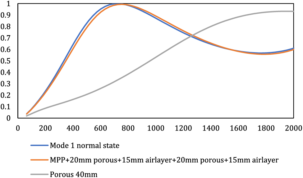
Figure 8: The effect of changing the arrangement of mode 1 on the overall behavior of the composite
Fig. 8 illustrates that altering the arrangement of mode 1 yielded negligible changes, yielding only marginal enhancements in behavior at higher frequencies. Conversely, the original mode 1 configuration exhibited superior performance, particularly in the realm of low frequencies.
3.7 The Effect of the Overall Depth of the MPP Cavity
The impact of varying the overall depth behind the cavity in mode 1 on the composite’s overall behavior was examined in the next step. The objective was to discern the magnitude of influence exerted by this depth on composite behavior. To this end, three distinct depths–30, 40, and 50 mm–were explored. Across all scenarios, the air gap remained constant at 10 mm, with alterations confined to the thickness of the porous material, set at 20, 30, and 40 mm. The outcomes of this exploration are presented in Fig. 9.
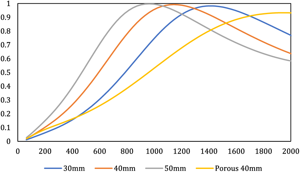
Figure 9: Influence of overall depth thickness behind the cavity on composite behavior via varying porous material thickness while keeping air layer thickness constant
As depicted in Fig. 9, elevating the depth thickness of the cavity positioned behind the MPP through an augmentation in the porous material thickness leads to an enhancement in the acoustic performance of the composite at lower frequencies. This alteration causes the resonance peak to escalate and shift towards lower frequencies. For instance, with an increase in the rear depth of the MPP chamber from 30 to 50 mm, the resonance peak shifts from 1500 to 900 Hz. It is important to acknowledge that although the resonance peak has undergone a shift towards lower frequencies, the actual magnitudes of the resonance peak values have not displayed substantial alterations. As highlighted in earlier sections, one effective approach to augment absorption within porous materials and shift the absorption peak towards lower frequencies involves increasing the thickness of the porous material. In a study by Hashemi et al., it was observed that elevating the thickness of the porous material led to a migration of the absorption peak to lower frequencies, while the peak values exhibited no considerable change [15]. Similarly, the research of Hashemi et al. also underscored that heightened thickness contributes to enhanced absorption at lower frequencies, consequently leading to a displacement of the absorption peak towards the lower frequency range [15,28].
In the next step, by keeping the thickness of the porous material constant, the effect of the thickness of the air gap in the cavity was investigated to understand the effect of the air layer on the acoustic behavior compared to the thickness of the porous material. By keeping the thickness of the porous material constant (10 mm), three air gaps of 20, 30, and 40 mm were checked. The overall depth of the cavity in these three cases was equal to 30, 40, and 50 mm. The results of investigating the effect of air layer thickness are shown in Fig. 10.
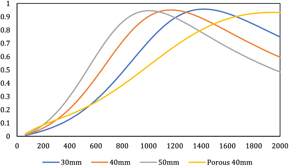
Figure 10: Influence of overall depth thickness behind the cavity on composite behavior via varying air layer thickness while keeping porous material thickness constant
As depicted in Fig. 10, it is evident that an augmentation in the depth of the air layer induces a shift of the absorption peak towards lower frequencies. For instance, when the air layer’s depth increases from 20 to 40 mm, the resonance peak shifts from 1473 to 993 Hz. However, noteworthy alterations in absorption are not observed concerning the resonance peak. In the context of the overall depth thickness of the cavity behind the MPP, the contribution of the porous material outweighs that of the air layer. This is evidenced by the fact that increasing the thickness of the porous material results in a more pronounced resonance peak, and the enhancement of the absorption coefficient at low frequencies is more substantial with the increase in porous material thickness compared to the increase in air layer thickness. Broadly comparing the impact of augmenting the depth of the MPP chamber, it can be deduced that instead of utilizing a 40 mm thickness of porous material, a combination of 20 mm porous material thickness and 10 mm air layer thickness alongside the MPP plate can yield significantly improved acoustic performance across lower frequencies. Consequently, this approach not only reduces costs and material consumption due to the reduced requirement for porous material manufacture but also minimizes the physical space taken up by the installation of the absorptive material. The findings of this segment of the study are also echoed in the research by Hashemi et al., reinforcing the congruence with the outcomes of the present study [15,34].
An alternative strategy to enhance acoustic performance at lower frequencies involves the selection of distinct porous materials characterized by varying effective parameters such as airflow resistivity, tortuosity, and porosity. Opting for porous materials with higher values of airflow resistivity and tortuosity can yield a heightened absorption coefficient at lower frequencies. This phenomenon can be attributed to the intricate and convoluted path sound waves traverse within porous materials possessing elevated airflow resistivity or tortuosity. This intricate path significantly impedes sound propagation, leading to a more substantial conversion of sound energy into heat. Moreover, the incorporation of materials with higher density, within certain limits, can yield improved acoustic performance. This is due to the interplay between increased density, airflow resistivity, and tortuosity, collectively contributing to enhanced sound absorption [15]. A case in point is Rusli et al.’s investigation, where the coupling of MPP with pineapple and palm fibers was explored. The study concluded that the utilization of pineapple leaf fibers, characterized by higher density compared to palm fibers, led to an augmented absorption coefficient at lower frequencies [35].
3.8 Validation of Impedance Tube Results with FEM Modeling
The validation process of simulation outcomes using the Finite Element Method (FEM) and direct measurements through an impedance tube across varying thicknesses demonstrated minimal disparities between these two approaches (Fig. 11). The thin line depicted in Fig. 11 corresponds to the characteristics of date palm fiber, specifically exhibiting a thickness measuring 4 cm and a density of 200 kg/m³, mentioned in [19]. Also, the thick line represents the modeling conducted through the implementation of the JCA model utilizing FEM simulations within the COMSOL software.
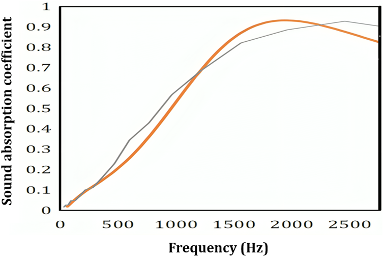
Figure 11: Validation of impedance tube results with FEM modeling (Thick line: JCA in FEM, Thin line: impedance tube)
The observed discrepancies can be attributed to the non-uniform surface impedance of fabricated samples in practical settings, along with potential errors during fabrication and measurement processes, often overlooked in FEM simulations [16]. Sources of non-uniform surface impedance might include material defects, irregularities, variations in composition, environmental factors, or measurement errors. These variations can introduce uncertainties in measurements and affect the reliability of experimental data, hindering the validation of theoretical models. Understanding these sources is crucial for accurate characterization and validation of acoustic properties in real-world applications. While impedance tube measurements ensure precise sample evaluation, the acquisition cost of an impedance tube, complexities in setting up an acoustic environment, and time limitations collectively drive researchers towards software-driven acoustic modeling and mathematical simulations. Additionally, considering the profound influence of structural parameters like panel thickness, hole diameter, and air gap on MPP’s acoustic characteristics, achieving the optimal condition necessitates numerous sample iterations. The significant expenses associated with impedance tube sound absorption measurements and the considerable costs incurred in manufacturing each sample using 3D printing and CNC highlight the advantage of employing simulation methods to achieve the optimum state. This transition not only reduces expenses and time investments but also streamlines the research process.
A potential weakness of the FEM in COMSOL was its limitation in accommodating certain crucial models, such as the Tarnow model. Despite this constraint, the software demonstrated overall robustness and convenience in conducting the study.
Future investigations are advised to explore diverse combinations of porous materials and MPPs, including dual layers of each, followed by experimental acoustic performance evaluation using an impedance tube. Subsequent comparison of the experimental outcomes with various modeling techniques like Delany Bazley and Miki against FEM can provide an enriched comprehension of the robustness of FEM concerning experimental methodologies.
The composite modeling of a hybrid configuration comprising date palm fiber-based porous material and an MPP layer revealed the influential role of multiple factors in determining the resonance frequency and bandwidth of the composite. These factors encompass the hole diameter, plate thickness, porosity percentage of the MPP layer, and the overall depth thickness behind the MPP chamber. This investigation underscores that achieving an extended bandwidth towards lower frequencies is best accomplished by situating the MPP layer in front of the porous material. Conversely, for enhancing absorption at higher frequencies, optimal outcomes can be obtained with the porous material preceding the MPP layer. Furthermore, the diameter of the hole, plate thickness and porosity percentage emerged as key determinants of the absorption peak, bandwidth, and resonance frequency, respectively. Diminishing the hole diameter and perforation ratio, coupled with amplifying the plate thickness, yielded improved acoustic performance, particularly at lower frequencies. Additionally, augmenting the depth of the cavity behind the MPP, achieved through increased porous material or air layer thickness, yielded enhanced acoustic performance at lower frequencies. Remarkably, the impact of increased porous material thickness outweighed that of the air layer in heightening the absorption peak and lowering the resonance frequency. Consequently, rather than employing a highly thick porous material with suboptimal performance at lower frequencies, adopting a configuration with halved porous layer thickness, along with an MPP layer and air layer, proved to be a more efficient solution. This strategy not only enhanced performance but also minimized costs and spatial requirements. One practical application of this study pertains to indoor settings like homes and offices where speech frequencies predominantly range between 500 to 1000 Hz. Implementing the configurations suggested in this study could effectively address issues associated with reverberation in these environments. Importantly, this study demonstrated the accuracy of numerical methods such as the Finite Element Method (FEM) compared to direct methodologies. This study showed that achieving the optimal acoustic state for the MPP/material composite does not require extensive and expensive sample production, despite the influence of various factors. This comparative efficacy significantly reduces the substantial expenses associated with laboratory-based testing.
Acknowledgement: The author extends gratitude to all individuals who contributed to the completion of this study.
Funding Statement: The author received no specific funding for this study.
Author Contributions: The author confirms contribution to the paper as follows: study conception and design; data collection; analysis and interpretation of results; draft manuscript preparation: Mohammad Javad SheikhMozafari.
Availability of Data and Materials: Data will be made available on request.
Conflicts of Interest: The author declares that he has no conflicts of interest to report regarding the present study.
References
1. Rastegar, N., Ershad-Langroudi, A., Parsimehr, H., Moradi, G. (2022). Sound-absorbing porous materials: A review on polyurethane-based foams. Iranian Polymer Journal, 31, 83–105. [Google Scholar]
2. Kishore, S., Sujithra, R., Dhatreyi, B. (2021). A review on latest acoustic noise mitigation materials. Materials Today: Proceedings, 47, 4700–4777. [Google Scholar]
3. Yang, M., Sheng, P. (2017). Sound absorption structures: From porous media to acoustic metamaterials. Annual Review of Materials Research, 47, 83–114. [Google Scholar]
4. Zhang, C., Li, H., Gong, J., Chen, J., Li, Z. et al. (2023). The review of fiber-based sound-absorbing structures. Textile Research Journal, 93(1–2), 434–449. [Google Scholar]
5. Jang, E. S. (2023). Sound absorbing properties of selected green material—A review. Forests, 14(7), 1366. [Google Scholar]
6. Taban, E., Amininasab, S., Mehrzad, S., Fattahi, M., Tajik, L. et al. (2022). Comparison of experimental and empirical approaches for determination of sound absorption properties of bagasse and cornhusk fibers. Journal of Natural Fibers, 19(14), 9024–9038. [Google Scholar]
7. Haghighat, M., Samaei, S. E., Amininasab, S., Faridan, M., Mehrzad, S. et al. (2023). The impact of fiber size on the sound absorption behavior of composites made from sugarcane bagasse wastes fibers. Journal of Natural Fibers, 20(1), 2175760. [Google Scholar]
8. Taban, E., Tajpoor, A., Faridan, M., Samaei, S. E., Beheshti, M. H. (2019). Acoustic absorption characterization and prediction of natural coir fibers. Acoustics Australia, 47, 67–77. [Google Scholar]
9. Koruk, H. (2022). Assessment of the measurement and prediction methods for the acoustic properties of natural fiber samples and evaluation of their properties. Journal of Natural Fibers, 19(13), 6283–6311. [Google Scholar]
10. Etemadinezhad, S., Samaei, S. E., Taban, E., Faridan, M. (2022). Experimental and theoretical investigation of the acoustic absorbers fabricated from natural kenaf fibres and rice husk. Journal of Natural Fibers, 19(16), 15045–15057. [Google Scholar]
11. Cao, L., Fu, Q., Si, Y., Ding, B., Yu, J. (2018). Porous materials for sound absorption. Composites Communications, 10, 25–35. [Google Scholar]
12. Berglund, B., Hassmen, P., Job, R. S. (1996). Sources and effects of low-frequency noise. The Journal of the Acoustical Society of America, 99(5), 2985–3002. [Google Scholar] [PubMed]
13. Arjunan, A., Baroutaji, A., Robinson, J. (2021). Advances in acoustic metamaterials. In: Encyclopedia of smart materials, vol. 3, pp. 1–10. UK. [Google Scholar]
14. Rezaieyan, E., Taban, E., Mortazavi, S. B., Khavanin, A., Asilian, H. et al. (2022). Acoustic properties of 3D printed bio-degradable micro-perforated panels made of corkwood fiber-reinforced composites. Journal of Health and Safety at Work, 12(2), 367–383. [Google Scholar]
15. Hashemi, Z., Monazzam Esmailpour, M., Nasirzadeh, N., Farvaresh, E., Beigzadeh, Z. et al. (2022). Estimation of sound absorption behavior of combined panels comprising kenaf fibers and micro-perforated plates below 2500 Hertz. Journal of Health and Safety at Work, 12(4), 872–894. [Google Scholar]
16. de Sousa, AC., Deckers, E., Claeys, C., Desmet, W. (2021). On the assembly of Archimedean spiral cavities for sound absorption applications: Design, optimization and experimental validation. Mechanical Systems and Signal Processing, 147, 107102. [Google Scholar]
17. Nisa, A. K., Prasetiyo, I., Mandasari, M. I. (2023). Implementation of parameter optimization method on hybrid configuration micro-perforated panel (MPP) as a broadband sound absorber. AIP Conference Proceedings, vol. 2580, no. 1. USA, AIP Publishing. [Google Scholar]
18. Hamdan, N. I., Zainulabidin, M. H., Kassim, A. S. M. (2021). A review on the development of panel and membrane sound absorbers. International Journal of Integrated Engineering, 13(1), 60–74. [Google Scholar]
19. Taban, E., Khavanin, A., Ohadi, A., Putra, A., Jafari, A. J. et al. (2019). Study on the acoustic characteristics of natural date palm fibres: Experimental and theoretical approaches. Building and Environment, 161, 106274. [Google Scholar]
20. Taban, E., Khavanin, A., Faridan, M., Samaei, S., Samimi, K. et al. (2020). Comparison of acoustic absorption characteristics of coir and date palm fibers: Experimental and analytical study of green composites. International Journal of Environmental Science and Technology, 17, 39–48. [Google Scholar]
21. Taban, E., Khavanin, A., Jafari, A. J., Faridan, M., Tabrizi, A. K. (2019). Experimental and mathematical survey of sound absorption performance of date palm fibers. Heliyon, 5(6), e01977. [Google Scholar] [PubMed]
22. Taban, E., Amininasab, S., Soltani, P., Berardi, U., Abdi, D. D. et al. (2021). Use of date palm waste fibers as sound absorption material. Journal of Building Engineering, 41, 102752. [Google Scholar]
23. Taban, E., Khavanin, A., Ohadi, A., jonidi, A., faridan, M. (2019). Experimental study and modelling of date palm fibre composite acoustic behaviour using differential evolution algorithm. Iran Occupational Health Journal, 16(2), 94–108. [Google Scholar]
24. Berardi, U., Iannace, G. (2015). Acoustic characterization of natural fibers for sound absorption applications. Building and Environment, 94, 840–852. [Google Scholar]
25. Asour, A. A., Kolahdouzi, M., Hashemi, Z. (2021). Impact of layout sequence of the natural and synthetic adsorbents in double-layered composites on improving the natural fiber acoustic performance using the numerical finite element method. Journal of Health and Safety at Work, 11(3), 368–383. [Google Scholar]
26. Beheshti, M. H., Khavanin, A., Safari Varyani, A., Yahya, M. N. B., Alami, A. et al. (2022). Improving the sound absorption of natural waste material-based sound absorbers using micro-perforated plates. Journal of Natural Fibers, 19(13), 5199–5210. [Google Scholar]
27. Li, X., Liu, B., Wu, Q. (2022). Enhanced low-frequency sound absorption of a porous layer mosaicked with perforated resonator. Polymers, 14(2), 223. [Google Scholar] [PubMed]
28. Bansod, P. V., Teja, T. S., Mohanty, A. R. (2017). Improvement of the sound absorption performance of jute felt-based sound absorbers using micro-perforated panels. Journal of Low Frequency Noise, Vibration and Active Control, 36(4), 376–398. [Google Scholar]
29. Sakagami, K., Kobatake, S., Kano, K. I., Morimoto, M., Yairi, M. (2011). Sound absorption characteristics of a single microperforated panel absorber backed by a porous absorbent layer. Acoustics Australia, 39(3), 95–100. [Google Scholar]
30. Li, G., Mechefske, C. K. (2010). A comprehensive experimental study of micro-perforated panel acoustic absorbers in MRI scanners. Magnetic Resonance Materials in Physics, Biology and Medicine, 23, 177–185. [Google Scholar]
31. Prasetiyo, I., Sarwono, J., Sihar, I. (2016). Study on inhomogenous perforation thick micro-perforated panel sound absorbers. Journal of Mechanical Engineering and Sciences, 10(3), 2350–2362. [Google Scholar]
32. Hamdan, N. I., Zainulabidin, M. H., Kasron, M. Z., Kassim, A. S. M. (2018). Effect of perforation size on sound absorption characteristics of membrane absorber. International Journal of Integrated Engineering, 10(4), 27–34. [Google Scholar]
33. Liu, Z., Zhan, J., Fard, M., Davy, J. L. (2017). Acoustic measurement of a 3D printed micro-perforated panel combined with a porous material. Measurement, 104, 233–236. [Google Scholar]
34. Chin, D. D. V. S., Yahya, M. N. B., Din, N. B. C., Ong, P. (2018). Acoustic properties of biodegradable composite micro-perforated panel (BC-MPP) made from kenaf fibre and polylactic acid (PLA). Applied Acoustics, 138, 179–187. [Google Scholar]
35. Rusli, M., Nanda, R. S., Dahlan, H., Bur, M. (2020). Sound absorption characteristics of sandwich panel made from double leaf micro-perforated panel and natural fiber. IOP Conference Series: Materials Science and Engineering, 815, 01201. [Google Scholar]
Cite This Article
 Copyright © 2024 The Author(s). Published by Tech Science Press.
This work is licensed under a Creative Commons Attribution 4.0 International License , which permits unrestricted use, distribution, and reproduction in any medium, provided the original work is properly cited.
 Downloads
 Citation Tools