
 Submit a Paper
 Propose a Special lssue
 Open Access
ARTICLE

Numerical Simulation of Low Cycle Fatigue Behavior of Ti2AlNb Alloy Subcomponents
1
Materials Evaluation Center for Aeronautical and Aeroengine Application, AECC Beijing Institute of Aeronautical Materials,
Beijing, 100095, China
2
Faculty of Civil Engineering and Mechanics, Jiangsu University, Zhenjiang, 212013, China
3
College of Mechanical Engineering, Yangzhou University, Yangzhou, 225127, China
* Corresponding Author: Wenfeng Hao. Email:
(This article belongs to the Special Issue: Mechanical Reliability of Advanced Materials and Structures for Harsh Applications)
Computer Modeling in Engineering & Sciences 2023, 136(3), 2655-2676. https://doi.org/10.32604/cmes.2023.025749
Received 28 July 2022; Accepted 12 October 2022; Issue published 09 March 2023
 View Full Text
 Download PDF
Abstract
Many titanium alloy subcomponents are subjected to fatigue loading in aerospace engineering, resulting in fatigue failure. The fatigue behavior of Ti2AlNb alloy subcomponents was investigated based on the Seeger fatigue life theory and the improved Lemaitre damage evolution theory. Firstly, the finite element models of the standard openhole specimen and Y-section subcomponents have been established by ABAQUS. The damage model parameters were determined by fatigue tests, and the reliability of fatigue life simulation results of the Ti2AlNb alloy standard open-hole specimen was verified. Meanwhile, the fatigue life of Ti2AlNb alloy Y-section subcomponents was predicted. Under the same initial conditions, the average error of fatigue life predicted by two different models was 20.6%. Finally, the effects of loading amplitude, temperature, and Y-interface angle on fatigue properties of Ti2AlNb Y-section subcomponents were investigated. These results provide a new idea for evaluating the fatigue life of various Ti2AlNb alloy subcomponents.Keywords
Advances in the aerospace industry require new lightweight materials and complex integral component forming technologies to improve fuel efficiency and payloads. Ti2AlNb alloy has good plasticity and fracture toughness at room temperature, creep and fatigue resistance at a high temperature, high Young’s modulus, and specific strength. Compared with the traditional high-temperature titanium alloy, the upper limit of application temperature of Ti2AlNb alloy exceeds 600°C and reaches 650°C∼700°C [1–4].
Many titanium alloy subcomponents are subjected to fatigue loading in aerospace engineering, resulting in fatigue failure. The fatigue behavior of Ti2AlNb alloy subcomponents is fundamental. The fatigue properties of Ti2AlNb alloy were mainly studied by analyzing the influence of microstructure, alloy composition and surface treatment. Through the study of the Orthorhombic structure (O phase), the formation mechanism of Ti2AlNb alloy is diverse and complex, and the formation of the material is strongly dependent on the thermal machining process [5–8]. When the O phase layer is thick, the longer the slip path, the lower the fatigue life. The thin O phase layer and the dense O/B2 phase interface can improve the fatigue crack initiation resistance. By adjusting the ratio of Al/Nb or adding alloying elements, such as Mo, Zr, Fe, Ta, W, Si and V, the mechanical properties of Ti2AlNb alloy, such as strength, plasticity, oxidation resistance and creep resistance, have been significantly changed [9–12]. For instance, W effectively improves the high temperature tensile strength of Ti2AlNb alloy from 752 to 1123 MPa [13]. Zhang et al. [14,15] studied the effect of cooling rate on the microstructure and tensile properties of Ti2AlNb alloy. Chen et al. [16] studied the effect of shot peening on the fatigue performance of Ti2AlNb. They measured the residual stress of the specimen after glass fine shot peening by X-ray diffraction and electropolishing. Based on the image crystal plasticity model, Fu et al. [17] studied the influence of size and distribution for the O phase on the fracture properties of Ti2AlNb superalloy. After shot peening, residual compressive stress was introduced into the surfaces of samples, which offset part of the tensile stress, delayed the initiation and propagation of cracks, and significantly increased the fatigue strength limit from 170 to 360 MPa and the high cycle fatigue life is prolonged more than 25 times [16,18]. The study of fatigue properties and deformation behaviour of Ti2AlNb alloy focuses on the material parts, and the fatigue behavior of subcomponents needs further study.
The fatigue life prediction of titanium alloy can be divided into three main criteria: stress criteria [19,20], energy criteria [21–23] and strain criteria [24–26]. The stress criterion is suitable for the life prediction of High Cycle Fatigue (HCF). The energy criterion considers that material damage accumulates strain energy caused by stress. When the energy reaches the critical value, the material will fail, and it cannot reflect the difference in the influence of various stress (strain) components on the material failure. The strain criterion of Morrow et al. [22] has been widely applied to the fatigue life prediction of elastic-plastic materials under Low Cycle Fatigue (LCF). Based on the strain criterion, Bäumel et al. [27] first found that a uniform description of fatigue parameters of different types of metal materials would lead to errors, so fatigue parameter expressions of steel, titanium and aluminium were given respectively. Seeger theory general slope method has significant advantages in the fatigue life prediction of titanium alloys. Continuum Damage Mechanics (CDM) has been rapidly developed and applied in recent years. CDM theory connects fatigue with microcrack evolution and further develops the traditional fatigue theory [28–31]. Compared with the classical fatigue theory, CDM theory is more consistent with the microscopic mechanism of the fatigue process observed in the experiments. The damage variable can measure the fatigue damage process more directly, which is convenient for considering the fatigue damage. Zhou et al. [32,33] improved the Lemaitre damage evolution model and applied the CDM method to fatigue damage and life prediction of titanium alloy TC4 materials and components, achieving excellent accuracy.
To sum up, the fatigue behavior of Ti2AlNb alloy subcomponents is still an open question. Seeger fatigue life theory and the improved Lemaitre damage evolution theory are used to predicting the fatigue life of Ti2AlNb alloy standard open-hole specimen and Y-section subcomponents. The research method has a particular reference significance for predicting the fatigue life of Ti2AlNb alloy subcomponents and provides a new idea for evaluating the fatigue life of various engineering structures.
Seeger theory has been widely used to estimate the elastic-plastic stress and strain of notched parts under uniaxial or multiaxial stress (monotone and cyclic loading). Its accuracy has also been verified in relevant experiments [34].
where
The relation between the real local stress amplitude and durability is:
where b is the fatigue strength exponent (Basquin’s exponent),
The true fracture strength (or stress) is shown to be:
where
The fatigue ductility coefficient,
where
Fatigue life can also be approximated by Eq. (5).
The fatigue strength exponent will usually be between −0.05 and −0.12. The fatigue ductility exponent, c, will usually be between −0.5 and −0.7.
From Eqs. (1) and (2), the following relation can be deduced:
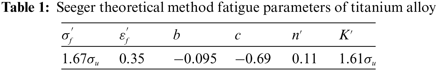
Seeger theory involves fatigue parameters as shown in Table 1, a = 1.0 when
2.2 The Improved Lemaitre Damage Evolution Theory
In the framework of CDM, damage is defined as the development of pores in microscopic, submicroscopic, and macroscopic fracture processes of materials, which is accompanied by the deterioration of the mechanical properties of materials. The ‘damage’ does not correspond to the actual crack. In metallic materials, the damage usually has no directivity, called isotropic damage, and can be expressed as a scalar quantity.
According to the equivalent strain hypothesis proposed by Lemaitre and Desmorat, the effective stress acting on the effective area can be defined as:
where
According to the constitutive damage model proposed by Krajcinovic and Lemaitre, the fatigue damage of metal materials in LCF is mainly caused by accumulated plastic strain. The greater the cumulative plastic deformation, the more excellent the energy dissipation caused by damage.
Damage increment,
Damage strain energy release rate, Y, can be expressed as:
where S is material constant,
Substitute Eq. (10) into Eq. (9)
According to the study of Zhou et al. [32], Eq. (11) cannot sufficiently describe the phenomenon of a sharp increase in damage of titanium alloy materials before failure. Eq. (11) is improved as:
where
For the LCF behavior of metal materials, the Ramberg-Osgood cycle is usually adopted. Within a stable cycle, the plastic strain can be expressed as:
where
The equivalent stress difference,
where
Assuming that the damage changes very little in a cycle, it can be approximated that the damage variable D in Eq. (13) is a specific value. By differentiating both ends of Eq. (13), the plastic strain rate can be obtained:
By using the established damage constitutive relation Eqs. (13), (15), and damage evolution Eq. (12), the change process of D at any point in the whole fatigue process can be theoretically given through numerical analysis. When D reaches
where
In order to calculate
A. Within a cycle, the damage changes,
B. When
By differentiating both ends of Eq. (12):
For symmetric fatigue cycles, the hysteresis loop is central symmetry:
By substituting Eqs. (14), (15) and (17) into Eq. (18) and integrating them, the fatigue damage within a cycle can be obtained, that is, the cumulative damage of Ti2AlNb alloy in each loading cycle is:
where S is a variable mainly related to
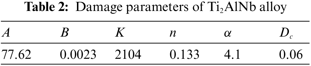
Material parameters involved in the damage model are shown in Table 2 [35].
2.3 Material Parameters of Ti2AlNb Alloy
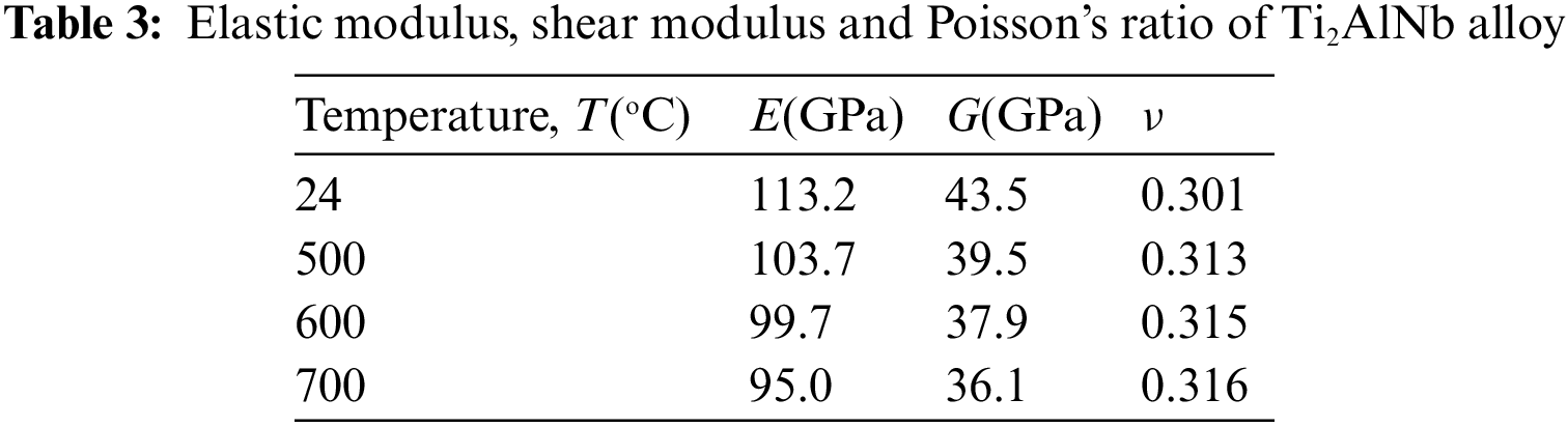
2.3.1 Young’s Modulus and Poisson’s Ratio
In order to measure the Elastic modulus and Poisson’s ratio of Ti2AlNb alloy, the bar specimens were tested using the dynamic (acoustic resonance) method according to ASTM E1875-20. The data required for the excerpt is shown in Table 3.
2.3.2 High Temperature Fatigue Tests of Standard Open-Hole Specimens
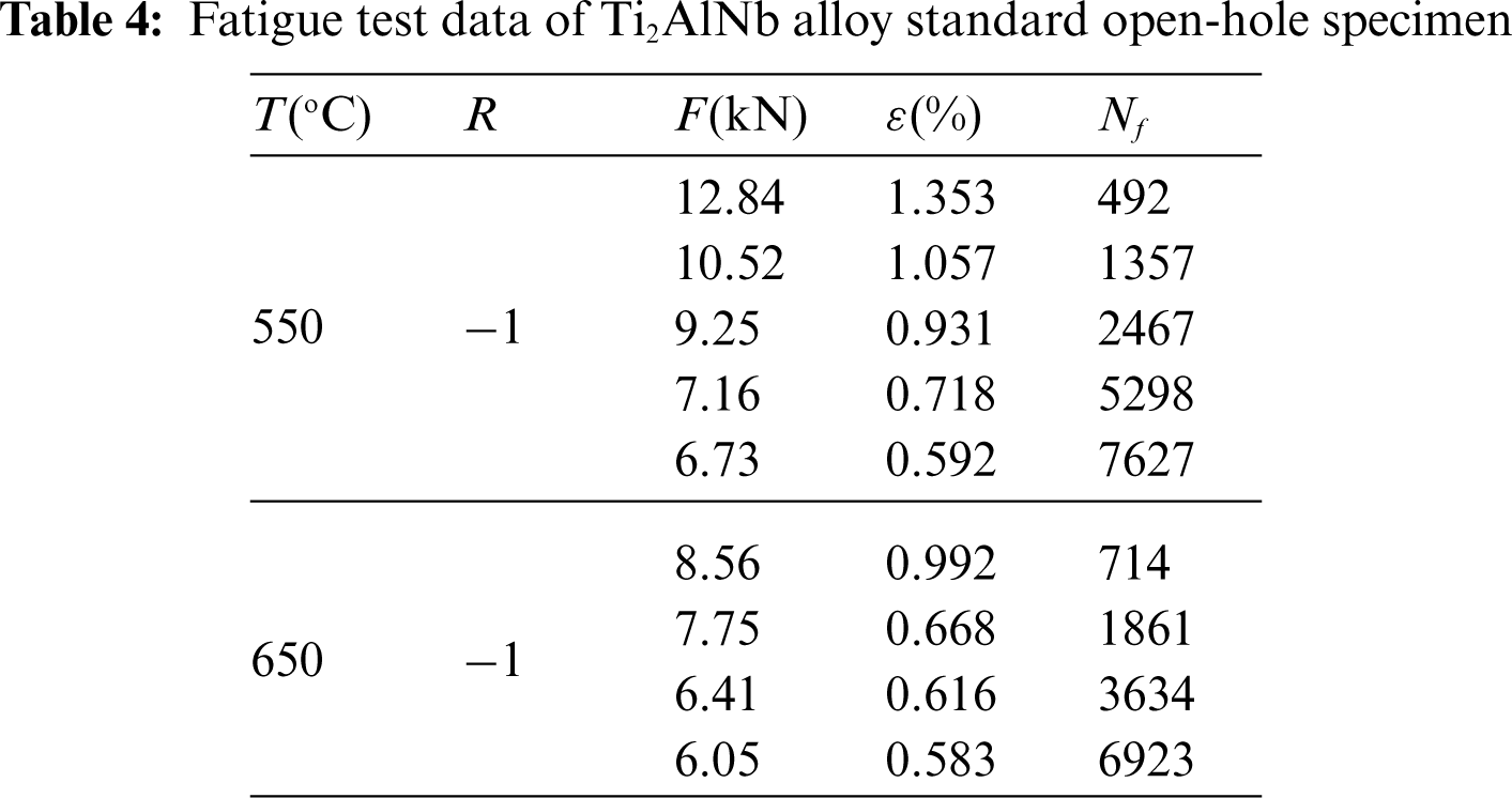
As the operating temperature range of Ti2AlNb alloy subcomponents includes 500°C∼700°C, the standard open-hole specimen was selected for the test, as shown in Fig. 1. The machine used in high temperature tensile test is shown in Fig. 2. The results of the static tensile test are shown in Fig. 3, the tensile strength of 550°C and 650°C is 990 and 908 MPa, respectively. The machine used in high temperature fatigue tensile test is shown in Fig. 4. The fatigue test results are shown in Table 4, where R is stress ratio, F is the maximum tensile force,
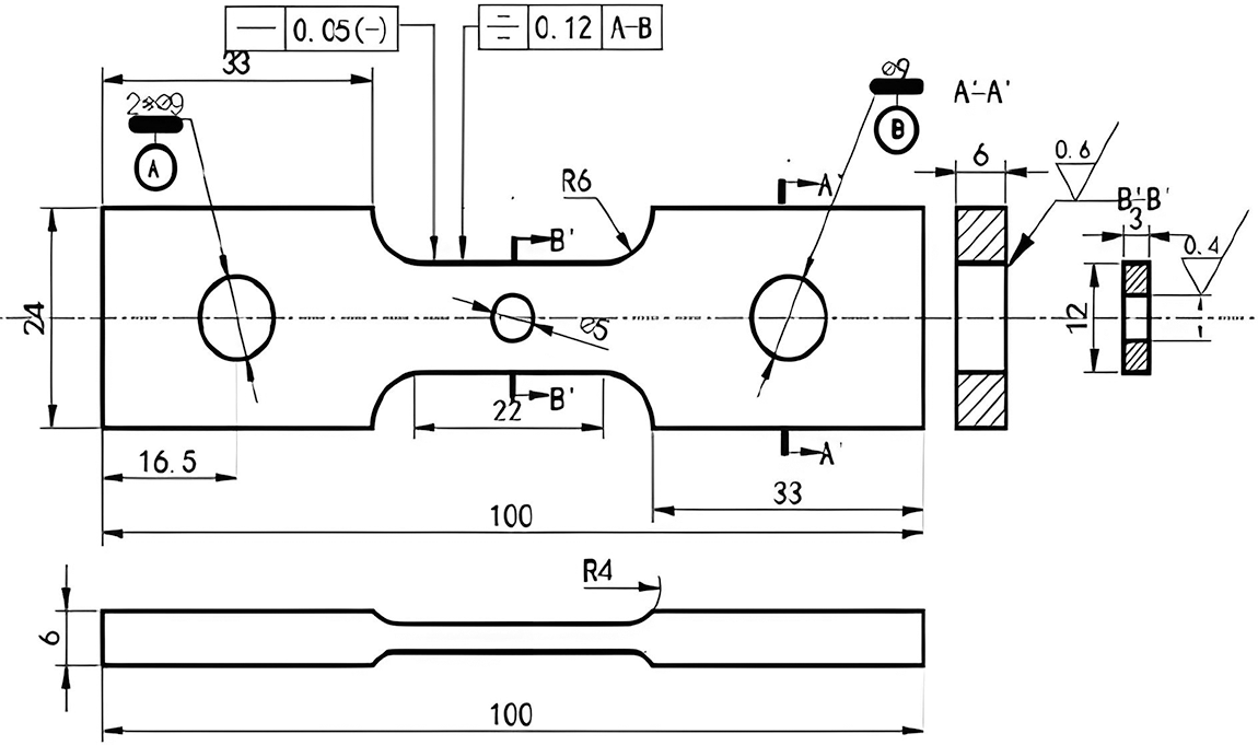
Figure 1: The size of Ti2AlNb alloy standard open-hole specimen

Figure 2: High temperature tensile testing machine (Tinius Olsen 100ST)
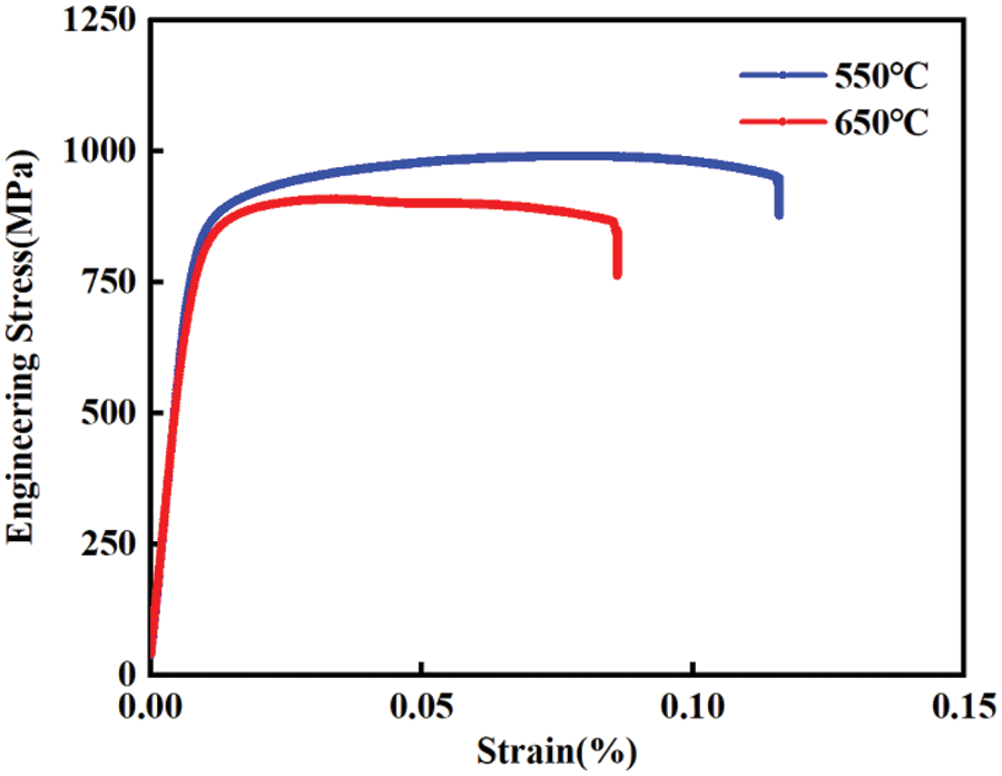
Figure 3: Tensile stress-strain curve

Figure 4: High temperature fatigue tensile testing machine (Instron 8801)
3 Numerical Simulations of Ti2AlNb Alloy Subcomponents
Numerical methods to simulate the behavior of materials can reduce the design and experimental costs, and the combination of experimental and simulated data is more consistent with the actual situation [36]. Firstly, the finite element model (FEM) of Ti2AlNb alloy standard open-hole specimens were analyzed for grid convergence. Then, the fatigue life of Ti2AlNb alloy standard open-hole specimens was predicted. The reliability of the two theoretical methods was analyzed and the fatigue parameters were determined. Finally, the two theoretical methods were used to predict the fatigue life of Ti2AlNb alloy Y-section subcomponents.
3.1 Mesh Size of Standard Open-Hole Specimens
The FEM model of Ti2AlNb alloy standard open-hole specimen was established in ABAQUS software. Three-dimensional four-node linear solid elements (C3D4) were used in the model. The element is defined by four nodes with three degrees of freedom for each node: translations in the nodal directions, x, y and z. To accurately obtain the local stress field of the specimen under cyclic loading, high-quality mesh discretization is needed [37].
The convergence solution independent of the mesh size is obtained in the numerical calculation after the mesh sensitivity analysis, as shown in Fig. 5. When the global mesh size (GS) is 2 mm, and the local mesh size (LS) is 0.2 mm, the numerical calculation accuracy and calculation time are the best for the Seeger fatigue life theory. A total of 31,765 elements are created, as shown in Fig. 6a. When the GS is 2 mm, and the LS is 1 mm, the numerical calculation accuracy and calculation time are the best for the improved Lemaitre damage evolution theory. A total of 15,265 elements are created, as shown in Fig. 6b.

Figure 5: Scatter diagrams of trend of solution convergence of Ti2AlNb alloy standard open-hole specimens model based on mesh size (Initial conditions:
Cite This Article
 Copyright © 2023 The Author(s). Published by Tech Science Press.
This work is licensed under a Creative Commons Attribution 4.0 International License , which permits unrestricted use, distribution, and reproduction in any medium, provided the original work is properly cited.
 Downloads
 Citation Tools