
 Submit a Paper
 Propose a Special lssue
 Open Access
ARTICLE

Performance Analysis of Intelligent Reflecting Surface Assisted Wireless Communication System
1 School of Computer Science and Cyber Engineering, Guangzhou University, Guangzhou, 510006, China
2 Key Laboratory of Advanced Manufacturing Technology, Ministry of Education, Guizhou University, Guiyang, 550025, China
3 Sichuan Key Laboratory of Indoor Space Layout Optimization and Security Guarantee, Chengdu Normal University, Chengdu, 611130, China
4 School of Information Science and Engineering, Southeast University, Nanjing, 210096, China
* Corresponding Author: Weiqiang Tan. Email:
(This article belongs to the Special Issue: Recent Advances in Backscatter and Intelligent Reflecting Surface Communications for 6G-enabled Internet of Things Networks)
Computer Modeling in Engineering & Sciences 2023, 137(1), 775-787. https://doi.org/10.32604/cmes.2023.027427
Received 28 October 2022; Accepted 13 December 2022; Issue published 23 April 2023
 View Full Text
 Download PDF
Abstract
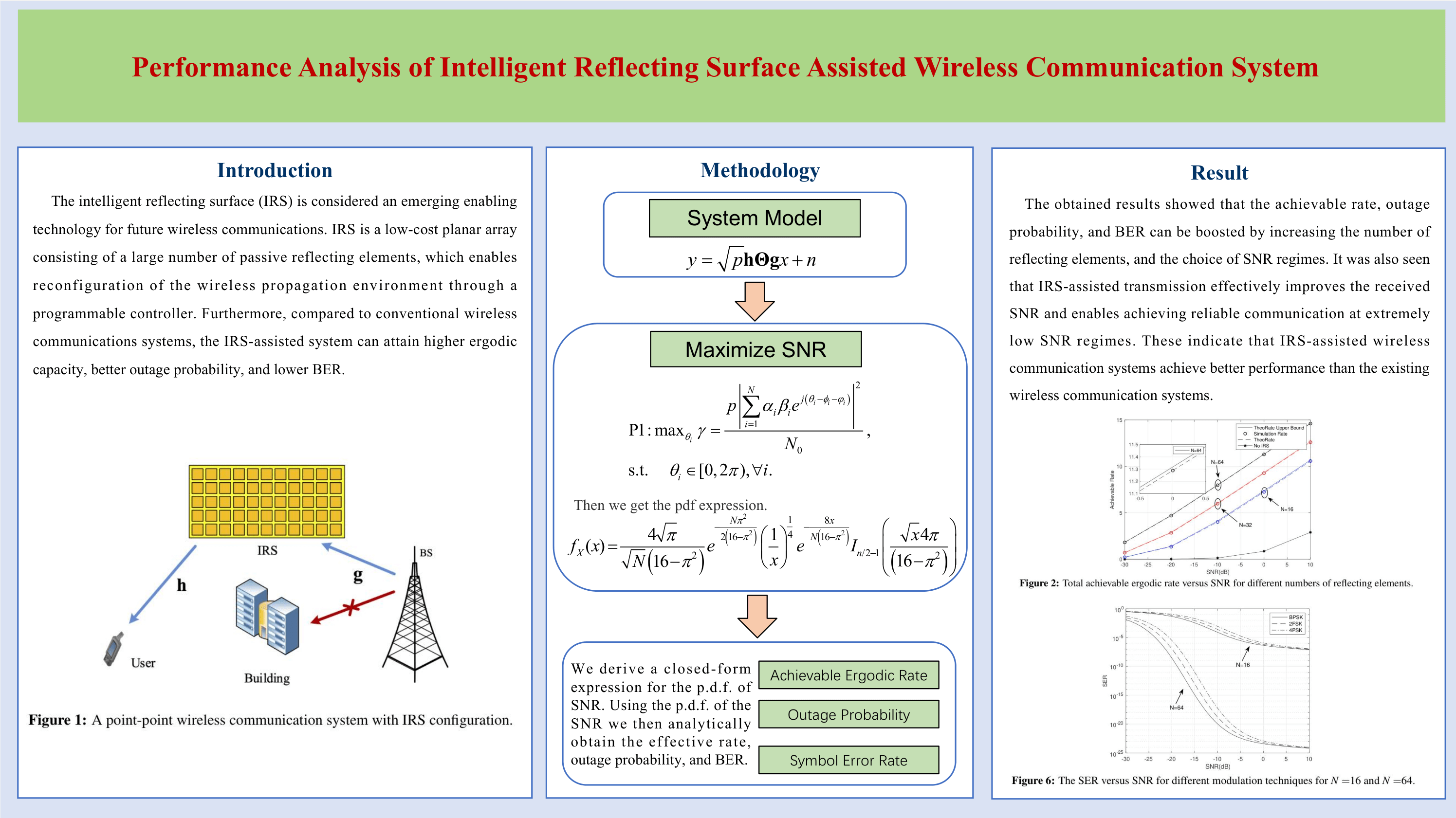
In this paper, we investigate the end-to-end performance of intelligent reflecting surface (IRS)-assisted wireless communication systems. We consider a system in which an IRS is deployed on a uniform planar array (UPA) configuration, including a large number of reflecting elements, where the transmitters and receivers are only equipped with a single antenna. Our objective is to analytically obtain the achievable ergodic rate, outage probability, and bit error rate (BER) of the system. Furthermore, to maximize the system’s signal-to-noise ratio (SNR), we design the phase shift of each reflecting element and derive the optimal reflection phase of the IRS based on the channel state information (CSI). We also derive the exact expression of the SNR probability density function (p.d.f.) and show that it follows a non-central Chi-square distribution. Using the p.d.f., we then derive the theoretical results of the achievable rate, outage probability, and BER. The accuracy of the obtained theoretical results is also verified through numerical simulation. It was shown that the achievable rate, outage probability, and BER could be improved by increasing the number of reflecting elements and choosing an appropriate SNR regime. Furthermore, we also find that the IRS-assisted communication system achieves better performance than the existing end-to-end wireless communication.Graphic Abstract
Keywords
With the evolution of modern communication systems, the beyond fifth-generation (B5G) and forthcoming sixth-generation (6G) are expected to provide ultrahigh throughput, massive connectivity, intelligent features, and high resource utilization [1–3]. The intelligent reflecting surface (IRS) is considered an emerging enabling technology for future wireless communications [4–6]. IRS is a low-cost planar array consisting of a large number of passive reflecting elements, which enables reconfiguration of the wireless propagation environment through a programmable controller. Furthermore, compared to conventional wireless communications systems, the IRS-assisted system can attain higher ergodic capacity, better outage probability, and lower BER [7,8].
The existing research on IRS-assisted MIMO communication systems is focused on system performance analysis, design optimization algorithms, and system architecture configuration. For system performance analysis, Han et al. [9] deduced the closed-form upper bound expression for the ergodic capacity of IRS-assisted communications in the Rice fading channel. For Rayleigh fading channels, Xu et al. [10] also showed that the received signal power could be approximated as the sum of two Gammas and two non-central Chi-squares and considered IRS-assisted communication system performance. With the results in [10], an analytical expression of the spectrum of wireless communication systems assisted by multiple IRS was obtained in [11], where the channel elements were assumed to follow a Gamma distribution. The research results showed that the IRS-assisted MIMO communication system could significantly improve system performance. The work in [12] studied the IRS-assisted communication channel model and showed that the equivalent channel of the IRS-assisted system follows the F distribution. The above research works are mainly based on statistical fading channel models such as Gaussian, Gamma, Rayleigh, or Rice random distributions. Nevertheless, experimental results show that the actual channels do not necessarily follow the assumption of independent and identical distribution. The channel behavior is also significantly affected by the carrier frequency and the configuration of the antenna array at the base station (BS) and the IRS. This is because the energy of wireless signals is often concentrated in a limited space, resulting in the existence of near- and far-field signals. The authors in [13] also investigated the secrecy performance of the simultaneously transmitting and reflecting reconfigurable intelligent surface under the Nakagami-m fading channels. They then derived analytical expressions for the secrecy outage probability (SOP) and showed that the system secrecy performance can be improved by increasing the number of configurable elements. In practice, an accurate channel model is a necessary condition for accurate analysis of the channel capacity. Furthermore, one needs to verify if the original research methods and the experimental conclusions are consistent. Therefore, it is an immediate need to establish an accurate channel model to characterize the performance limits of IRS-assisted mmWave MIMO systems.
In terms of designing optimization algorithms, the researchers designed active beamforming techniques at the BS and/or passive beamforming at the IRS. They then constructed an objective function to maximize performance indicators such as energy efficiency, spectral efficiency, latency, outage probability, bit error rate (BER), or computational complexity. In [14], the authors proposed an algorithm based on alternating optimization to design the optimal passive IRS beamforming to maximize energy efficiency. To reduce the computational complexity, Wu et al. [15] adopted the branch-and-bound method along with an exhaustive search method. They also proposed a unit-by-unit optimization algorithm to obtain passive beamforming assuming discrete reflection phase shifts. In [16], the authors also utilized the fixed-point iterative method and the manifold optimization algorithm to design the optimal passive beamforming and maximize system spectral efficiency. The computational complexity of the proposed method in [16] is however high due to multiple iterations. In [17], the authors converted the system spectral efficiency maximization problem into an SINR maximization problem and used the alternating direction multiplier method to derive the optimal IRS beamforming. By applying the power allocation scheme, Huang et al. [18] adopted the gradient descent algorithm and designed the optimal IRS beamforming to maximize energy efficiency. Furthermore, You et al. [19] proposed a channel estimation algorithm by controlling the overhead of IRS and joint optimization of the reflection phase shift. They then designed the transceiver that greatly improves the energy efficiency of the system. In the above research work, the authors utilized an ideal constant modulus phase based on the IRS reflection unit, where the base stations are assumed to have access to the perfect CSI. However, in the actual design, the IRS reflection unit has a discrete phase and it is difficult for the base station to obtain the perfect CSI. Therefore, the channel estimation and beamforming of mmWave massive MIMO systems in the case of inaccurate CSI and IRS discrete phases need to be investigated. In terms of system architecture configuration, Wang et al. [20] analyzed the IRS-assisted millimeter-wave massive MIMO system by joint optimization of the quantization phase shift for the analog and digital coding matrices assuming using IRS at the base stations. For this system, they then minimized the mean square error between the received symbols and the transmitted symbols. In [21], the authors studied the hybrid precoding design of multi-user IRS-assisted mmWave MIMO systems and performed MSE minimization by using the gradient projection method. Nevertheless, these works assume an all-digital high-precision analog-to-digital converter (ADC) architecture. In practice, however, the core high-precision ADC devices are not only expensive but also often consume lots of energy, especially for large bandwidths.
In this paper, we investigate the end-to-end performance of an IRS-assisted wireless communication system. In the considered system, the IRS is deployed to a uniform planar array (UPA) configuration with a large number of reflecting elements, and the transmitters and receivers are equipped with a single antenna. Our objective is to calculate the analytical expression of the achievable ergodic rate, outage probability, and BER of the system. To maximize the system’s SNR, we also design the phase shift of each reflecting element and derive the optimal reflection phase of the IRS in terms of the channel state information (CSI). We further derive the exact expression of the probability density function (p.d.f.) of the SNR, which follows non-central Chi-square distribution. Using p.d.f., we then derive the achievable rate, outage probability, and BER, and further verify their accuracy through numerical simulation.
Regarding the notation, bold upper and lower case letters such as
We consider a single-cell centralized IRS-assisted wireless communication system, where there is no direct communication between the base station and the user. The IRS is utilized to assist wireless communication between the BS and users as shown in Fig. 1. In particular, the IRS is mounted on the walls of the surrounding tall buildings. We also assume that there is a single-antenna base station that transmits signals and serves single-antenna users. The IRS consists of N reflecting elements and the reflecting elements are arranged within a rectangle. In practice, the IRS can be installed on the walls of buildings or roadside structures to help with signal transmission. Supposing that the transmitting signal is a Gaussian signal, the received signal assuming a high-precision ADC is
where
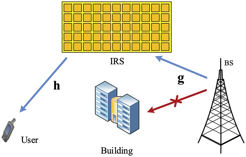
Figure 1: A point-point wireless communication system with IRS configuration
In the above,
In this paper, we assume ideal IRS reflection elements without power loss. A cascade channel consists of two channels from the BS to the IRS and from between the IRS and the user. The wireless channel also follows the Rayleigh fading where
and
where
In communication systems, analytical results can effectively characterize the system performance and the physical parameters can explore the performance trend and system parameters, e.g., the number of IRS elements, the number of transmit antennas at the base station, the number of users, and the transmit power of the base station. These parameters can accurately characterize the system’s achievable theoretical performance limits. Besides, we can utilize the derived analytical results as the benchmark and further optimize the physical parameters to boost the system performance under certain requirements. In the following section, we investigate the end-to-end performance of IRS-assisted wireless communication systems, where the IRS is deployed to a UPA configuration with a large number of reflecting elements.
In this section, we derive a closed-form expression for the p.d.f. of SNR. Using the p.d.f. of the SNR we then analytically obtain the effective rate, outage probability, and BER.
The IRS results in the co-existence of direct and indirect links. Here, however, we ignore the direct path and only consider the reflected path as in the slowly varying and flat fading channels. The received baseband signal reflected via the IRS with N passive elements is
Using (1), the instantaneous SNR at the user end is expressed as
where
To order to analyze the performance of the system, it is necessary to obtain the p.d.f. of SNR in (6). The problem formulation is as the following:
where
For the sake of brevity, let
where
In the above,
Considering the definition of the non-central Chi-squared distribution, it is easy to show that the random variable X follows a non-central Chi-square distribution with the degrees of freedom
For brevity, the p.d.f. of X is simplified as the following:
where
Therefore, the p.d.f of X can be further simplified to
In the following three sections, we will use the derived p.d.f. in (15) to analyze the key performance of the communication system including the achievable ergodic rate, outage probability, and symbol error rate.
3.2 Achievable Ergodic Rate Analysis
The achievable rate is an important service quality indicator in communication systems which represents the maximum theoretical achievable rate at the receiver. The achievable rate of the system using IRS assistance can be calculated from Shannon’s formula as
Using the p.d.f. of X, the system’s ergodic rate can be calculated as
As can be seen in (17), the exact derivation over the range of SNR regimes is mathematically intractable and the expectation operation needs to be calculated through all vector realizations of the random variables X involving the modified Bessel function of the first kind. Therefore, it is difficult to directly derive an exact expression of the achievable rate. Alternatively, we attempt to infer a tractable upper bound on the achievable rate using Jensen’s inequality. This enables us to draw engineering insights into the system’s performance. Here we note that for
By employing the derived p.d.f of X and substituting the (15) into (18), we have
where
3.3 Outage Probability Analysis
The outage probability is defined as the point that a given ergodic rate is not supported if the receiver power value falls below a threshold SNR. The outage probability is defined as
In wireless communications, the outage probability is an important quality of service indicator. If the communication quality drops to a certain level, communication interruption occurs. This is defined as the probability that the received SNR drops below the acceptable minimum threshold. To provide insight into the system performance, the diversity order is often used to evaluate the outage behaviors for communication systems. This measure describes how quickly the outage probability decreases with the increase of the received power. By applying the definition of outage probability in (15), we write
where
where
3.4 Symbol Error Rate Analysis
The symbol error rate is an indicator measuring the accuracy of data transmission within a specified time. It is often defined as the frequency of bit errors in the transmission process. The research on BER is of great significance to enhance the performance of wireless communication systems and to improve the quality of data transmission. The formula for calculating the BER is as follows:
where
From (24), one can see that it is hard to obtain the closed-form expression of the SER. Alternatively, this result can be evaluated numerically by using standard software packages such as Matlab or Mathematica.
In this section, we simulate and compare the performance of the system from different perspectives described in the previous section. We assume that the BS has a single antenna, the IRS is a UPA composed of N passive reflecting elements, and
Fig. 2 depicts the total achievable ergodic rate vs. SNR for different numbers of reflecting elements, including the theoretical analysis result, the upper bound, and the Monte Carlo simulation provided in (17), and (19), respectively. It is seen that the total achievable ergodic rate is significantly improved by increasing SNR. It is also seen that the analytical results are in good agreement with the Monte Carlo simulations validating the correctness of the upper bound obtained in (19). Moreover, the ergodic rate is significantly increased by increasing the number of emitted elements which indicates that the high SNR regimes can bring significant performance gains. For comparison, we also present the total rate of the system with different numbers of reflecting elements. It is seen that using a large number of reflecting elements leads to significant performance gains.
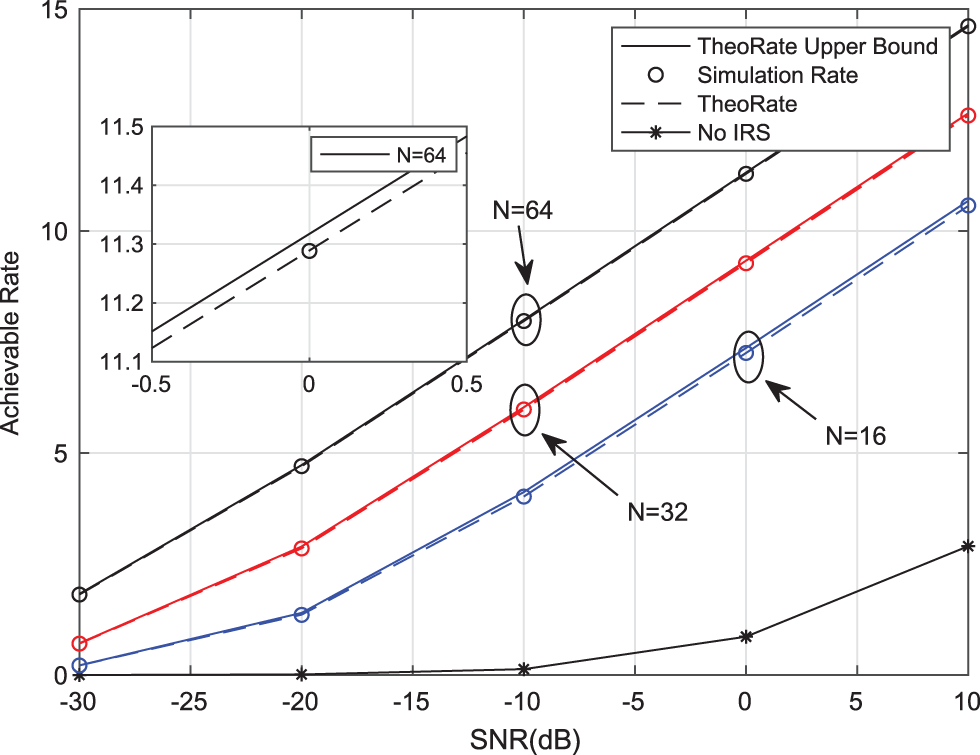
Figure 2: Total achievable ergodic rate vs. SNR for different numbers of reflecting elements
Fig. 2 depicts the total achievable ergodic rate vs. SNR for the different numbers of reflecting elements, which includes the theoretical analysis result, the upper bound, and the Monte Carlo simulation provided in (17), and (19), respectively. It can be seen intuitively that the total achievable ergodic rate improves significantly with the increase of SNR. Besides, we also see that the analysis results are in good agreement with the Monte Carlo simulation results, which validates the correctness of the upper bound of (19). Moreover, the ergodic rate increases significantly with the number of emitted elements which indicates that the high SNR regimes can bring significant performance gains. For comparison, we also depict the total rate of the system with different numbers of reflecting elements, showing that using a large number of reflecting elements can lead to significant performance gains.
Fig. 3 shows the total achievable ergodic rate vs. the number of reflecting elements. It is seen that the ergodic capacity significantly increases with the increasing numbers of reflecting elements. This indicates that the use of a large number of reflecting elements can lead to significant performance gains. Of course, when the number of reflected elements is small, there is a certain gap, but when the number of reflecting elements is about 30, the gap almost disappears. This further indicates that the use of a large number of reflecting elements brings significant performance gain.
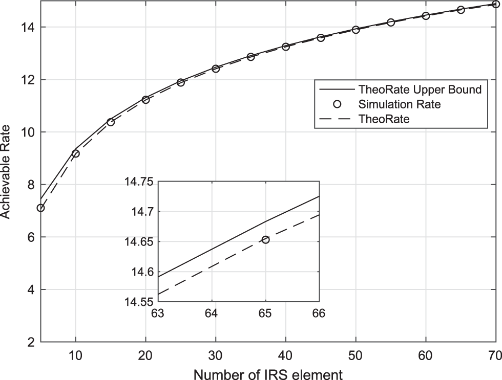
Figure 3: Total achievable ergodic rate vs. the number of reflecting elements
Fig. 4 shows the outage probability of the system vs. the number of reflecting elements. In the simulation, the minimum acceptable SNR and the average transmitted power
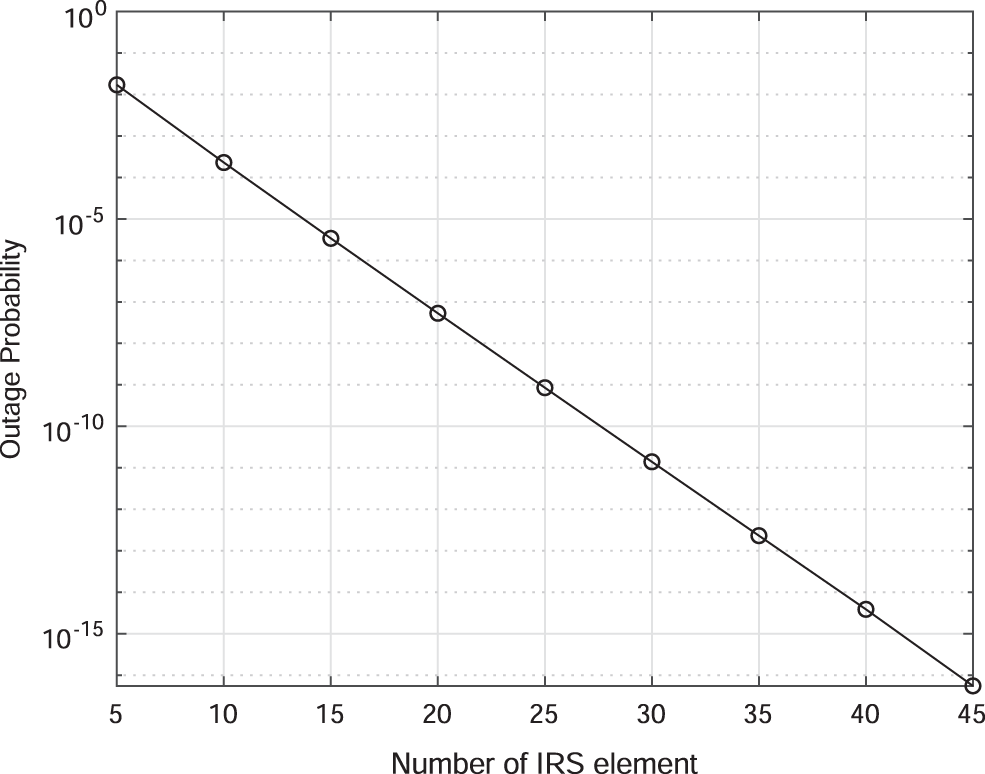
Figure 4: The outage probability vs. the number of reflecting elements
Figs. 5 and 6 present the SER vs. SNR. In Fig. 5, the BPSK system is considered and the performance is presented vs. the numbers of reflecting elements. In the simulations, the number of reflecting elements is set to N = 16, N = 64, and N = 100, and we consider BPSK (
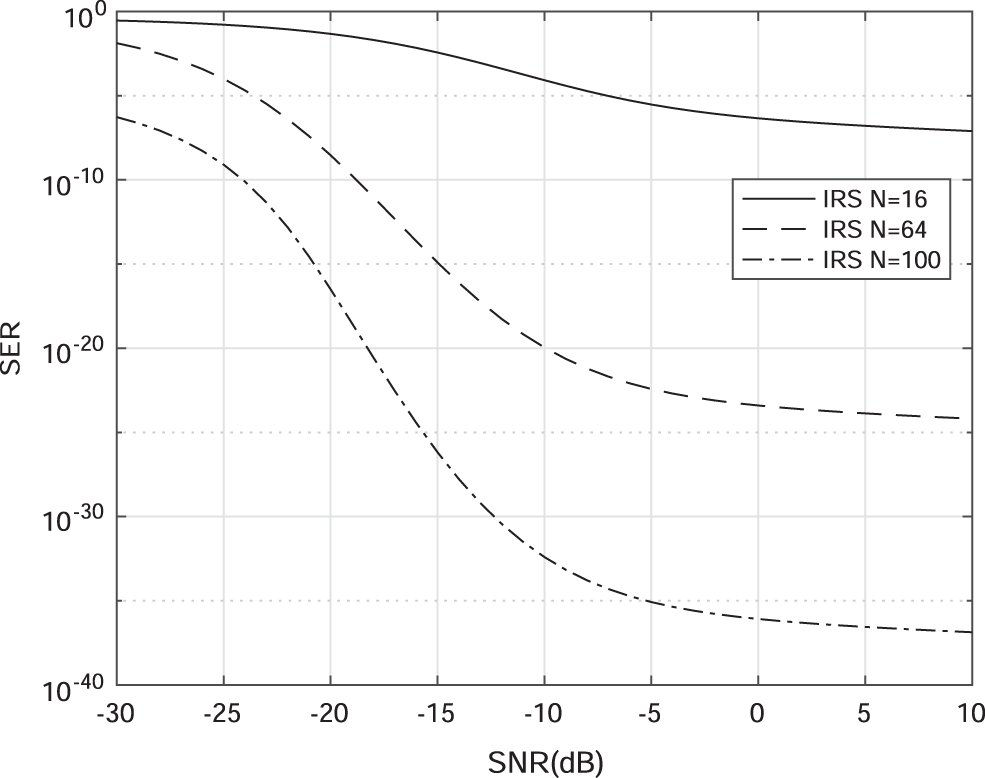
Figure 5: The binary phase shift keying (BPSK) vs. SNR for different numbers of reflecting elements
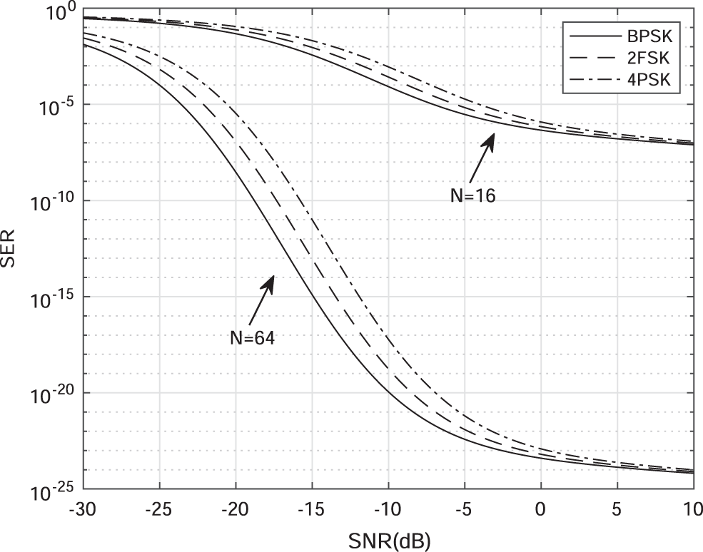
Figure 6: The SER vs. SNR for different modulation techniques for N =16 and N =64
We studied the end-to-end performance of an IRS-assisted wireless communication system. To maximize the system’s SNR, we designed the phase shifts of the reflecting elements and derived the optimal reflection phase of the IRS based on the perfect CSI. The exact expression of the p.d.f. of the SNR was also obtained, which follows a non-central Chi-square distribution. By utilizing the p.d.f. of the SNR, we further analytically derived the achievable rate, outage probability, and bit error rate and further confirmed their accuracy through numerical simulation. The obtained results showed that the achievable rate, outage probability, and BER could be boosted by increasing the number of reflecting elements, and the choice of SNR regimes. It was also seen that IRS-assisted transmission effectively improves the received SNR and enables achieving reliable communication at extremely low SNR regimes. These indicate that IRS-assisted wireless communication systems achieve better performance than the existing wireless communication systems.
Acknowledgement: The authors wish to express their appreciation to the reviewers for their helpful suggestions which greatly improved the presentation of this paper. And we would like to express our gratitude to EditSprings (https://www.editsprings.cn) for the expert linguistic services provided.
Funding Statement: This work was supported in part by the Joint Research Fund for Guangzhou University and Hong Kong University of Science and Technology under Grant No. YH202203, the Guangzhou Basic Research Program Municipal School (College) Joint Funding Project, the Research Project of Guizhou University for Talent Introduction under Grant No. [2020]61, the Cultivation Project of Guizhou University under Grant No. [2019]56, the Open Fund of Key Laboratory of Advanced Manufacturing Technology, Ministry of Education under Grant No. GZUAMT2021KF[01], the National Natural Science Foundation of China under Grant Nos. 51978089 and 62171119, the Key R&D Plan of Sichuan Science and Technology Department under Grant No. 22ZDYF2726, the Chengdu Normal University Scientific Research and Innovation Team under Grant Nos. CSCXTD2020B09, ZZBS201907, CS21ZC01, the Open Project of Intelligent Manufacturing Industry Technology Research Institute under Grant No. ZNZZ2208, the National Key Research and Development Program of China under Grant No. 2020YFB1807201, and Key research and development plan of Jiangsu Province under Grant No. BE2021013-3.
Conflicts of Interest: The authors declare that they have no conflicts of interest to report regarding the present study.
References
1. Wang, H., Xu, L., Yan, Z., Gulliver, T. A. (2020). Low-complexity MIMO-FBMC sparse channel parameter estimation for industrial big data communications. IEEE Transactions on Industrial Informatics, 17(5), 3422–3430. https://doi.org/10.1109/TII.2020.2995598 [Google Scholar] [CrossRef]
2. Zhang, Z., Xiao, Y., Ma, Z., Xiao, M., Ding, Z. et al. (2019). 6G wireless networks: Vision, requirements, architecture, and key technologies. IEEE Vehicular Technology Magazine, 14(3), 28–41. https://doi.org/10.1109/MVT.2019.2921208 [Google Scholar] [CrossRef]
3. Wang, H., Xiao, P., Li, X. (2022). Channel parameter estimation of mmWave MIMO system in urban traffic scene: A training channel-based method. IEEE Transactions on Intelligent Transportation Systems, 1–9. https://doi.org/10.1109/TITS.2022.3145363 [Google Scholar] [CrossRef]
4. Liu, H., Li, G., Li, X., Liu, Y., Huang, G. et al. (2022). Effective capacity analysis of STAR-RIS-Assisted NOMA networks. IEEE Wireless Communications Letters, 11(9), 1930–1934. https://doi.org/10.1109/LWC.2022.3188443 [Google Scholar] [CrossRef]
5. Tang, W., Li, X., Dai, J. Y., Jin, S., Zeng, Y. et al. (2019). Wireless communications with programmable metasurface: Transceiver design and experimental results. China Communications, 16(5), 46–61. https://doi.org/10.23919/j.cc.2019.05.004 [Google Scholar] [CrossRef]
6. Yu, X., Jamali, V., Xu, D., Ng, D. W. K., Schober, R. (2021). Smart and reconfigurable wireless communications: From IRS modeling to algorithm design. IEEE Wireless Communications, 28(6), 118–125. https://doi.org/10.1109/MWC.001.2100145 [Google Scholar] [CrossRef]
7. Li, G., Liu, H., Huang, G., Li, X., Raj, B. et al. (2021). Effective capacity analysis of reconfigurable intelligent surfaces aided NOMA network. EURASIP Journal on Wireless Communications and Networking, 2021(1), 1–16. https://doi.org/10.1186/s13638-020-01861-8 [Google Scholar] [CrossRef]
8. Li, X., Xie, Z., Chu, Z., Menon, V. G., Mumtaz, S. et al. (2022). Exploiting benefits of IRS in wireless powered NOMA networks. IEEE Transactions on Green Communications and Networking, 6(1), 175–186. https://doi.org/10.1109/TGCN.2022.3144744 [Google Scholar] [CrossRef]
9. Han, Y., Tang, W., Jin, S., Wen, C. K., Ma, X. (2019). Large intelligent surface-assisted wireless communication exploiting statistical CSI. IEEE Transactions on Vehicular Technology, 68(8), 8238–8242. https://doi.org/10.1109/TVT.2019.2923997 [Google Scholar] [CrossRef]
10. Xu, J., Liu, Y. (2021). A novel physics-based channel model for reconfigurable intelligent surface-assisted multi-user communication systems. IEEE Transactions on Wireless Communications, 21(2), 1183–1196. https://doi.org/10.1109/TWC.2021.3102887 [Google Scholar] [CrossRef]
11. Lyu, J., Zhang, R. (2020). Spatial throughput characterization for intelligent reflecting surface aided multiuser system. IEEE Wireless Communications Letters, 9(6), 834–838. https://doi.org/10.1109/LWC.2020.2972527 [Google Scholar] [CrossRef]
12. Makarfi, A. U., Rabie, K. M., Kaiwartya, O., Badarneh, O. S., Li, X. et al. (2020). Reconfigurable intelligent surface enabled IoT networks in generalized fading channels. 2020 IEEE International Conference on Communications (ICC), Dublin, Ireland, IEEE. [Google Scholar]
13. Li, X., Zheng, Y., Zeng, M., Liu, Y., Dobre, O. A. (2022). Enhancing secrecy performance for STAR-RIS NOMA networks. IEEE Transactions on Vehicular Technology, 1–6. https://doi.org/10.1109/TVT.2022.3213334 [Google Scholar] [CrossRef]
14. Wu, Q., Zhang, R. (2019). Intelligent reflecting surface enhanced wireless network via joint active and passive beamforming. IEEE Transactions on Wireless Communications, 18(11), 5394–5409. https://doi.org/10.1109/TWC.2019.2936025 [Google Scholar] [CrossRef]
15. Wu, Q., Zhang, R. (2019). Beamforming optimization for wireless network aided by intelligent reflecting surface with discrete phase shifts. IEEE Transactions on Communications, 68(3), 1838–1851. https://doi.org/10.1109/TCOMM.2019.2958916 [Google Scholar] [CrossRef]
16. Yu, X., Xu, D., Schober, R. (2020). Optimal beamforming for MISO communications via intelligent reflecting surfaces. 2020 IEEE 21st International Workshop on Signal Processing Advances in Wireless Communications (SPAWC), Oulu, Finland, IEEE. [Google Scholar]
17. Ning, B., Chen, Z., Chen, W., Fang, J. (2020). Beamforming optimization for intelligent reflecting surface assisted MIMO: A sum-path-gain maximization approach. IEEE Wireless Communications Letters, 9(7), 1105–1109. https://doi.org/10.1109/LWC.2020.2982140 [Google Scholar] [CrossRef]
18. Huang, C., Zappone, A., Alexandropoulos, G. C., Debbah, M., Yuen, C. (2019). Reconfigurable intelligent surfaces for energy efficiency in wireless communication. IEEE Transactions on Wireless Communications, 18(8), 4157–4170. https://doi.org/10.1109/TWC.2019.2922609 [Google Scholar] [CrossRef]
19. You, C., Zheng, B., Zhang, R. (2020). Channel estimation and passive beamforming for intelligent reflecting surface: Discrete phase shift and progressive refinement. IEEE Journal on Selected Areas in Communications, 38(11), 2604–2620. https://doi.org/10.1109/JSAC.2020.3007056 [Google Scholar] [CrossRef]
20. Wang, P., Fang, J., Yuan, X., Chen, Z., Li, H. (2020). Intelligent reflecting surface-assisted millimeter wave communications: Joint active and passive precoding design. IEEE Transactions on Vehicular Technology, 69(12), 14960–14973. https://doi.org/10.1109/TVT.2020.3031657 [Google Scholar] [CrossRef]
21. Pradhan, C., Li, A., Song, L., Vucetic, B., Li, Y. (2020). Hybrid precoding design for reconfigurable intelligent surface aided mmwave communication systems. IEEE Wireless Communications Letters, 9(7), 1041–1045. https://doi.org/10.1109/LWC.2020.2980225 [Google Scholar] [CrossRef]
22. Tan, W., Yang, X., Ma, S. (2021). Spectral efficiency of massive MIMO With LMMSE receivers under finite dimensional channels. IEEE Wireless Communications Letters, 11(1), 18–22. https://doi.org/10.1109/LWC.2021.3118700 [Google Scholar] [CrossRef]
23. Basar, E. (2019). Transmission through large intelligent surfaces: A new frontier in wireless communications. 2019 European Conference on Networks and Communications (EuCNC), Valencia, Spain, IEEE. [Google Scholar]
24. Abramowitz, M., Stegun, I. A. (1964). Handbook of mathematical functions with formulas, graphs, and mathematical tables, vol. 55. New York, USA: US Government printing office. [Google Scholar]
25. Tan, W., Ma, S. (2022). Antenna array topologies for mmWave massive MIMO systems: Spectral efficiency analysis. IEEE Transactions on Vehicular Technology, 71(12), 12901–12915. https://doi.org/10.1109/TVT.2022.3197600 [Google Scholar] [CrossRef]
26. Andrews, L. C. (1998). Special functions of mathematics for engineers, vol. 49. Washington State, USA: SPIE Press. [Google Scholar]
27. Karagiannidis, G. K., Lioumpas, A. S. (2007). An improved approximation for the Gaussian Q-function. IEEE Communications Letters, 11(8), 644–646. https://doi.org/10.1109/LCOMM.2007.070470 [Google Scholar] [CrossRef]
28. Gradshteyn, I. S., Ryzhik, I. M. (2014). Table of integrals, series, and products. San Diego, California, USA: Academic Press. [Google Scholar]
Cite This Article
 Copyright © 2023 The Author(s). Published by Tech Science Press.
This work is licensed under a Creative Commons Attribution 4.0 International License , which permits unrestricted use, distribution, and reproduction in any medium, provided the original work is properly cited.
 Downloads
 Citation Tools