
 Submit a Paper
 Propose a Special lssue
 Open Access
ARTICLE
Anti-Jamming Null Space Projection Beamforming Based on Symbiotic Radio
1 State Key Laboratory of Complex Electromagnetic Environment Effects on Electronics and Information System (CEMEE), Luoyang, 471000, China
2 Research and Innovation Center of Intelligent System, Longmen Laboratory, Luoyang, 471000, China
3 College of Information Engineering, Henan University of Science and Technology, Luoyang, 471000, China
4 Institute of Atmospheric Physics, Chinese Academy of Sciences (LAGEO), Beijing, 100000, China
5 Instituto de Telecomunicaes, Aveiro, 3800-005, Portugal
6 Chinese Academy of Agricultural Mechanization Sciences, Beijing, 100000, China
* Corresponding Author: Baofeng Ji. Email:
(This article belongs to the Special Issue: Recent Advances in Backscatter and Intelligent Reflecting Surface Communications for 6G-enabled Internet of Things Networks)
Computer Modeling in Engineering & Sciences 2024, 138(1), 679-689. https://doi.org/10.32604/cmes.2023.028667
Received 31 December 2022; Accepted 23 April 2023; Issue published 22 September 2023
 View Full Text
 Download PDF
Abstract
With the development of information technology, more and more devices are connected to the Internet through wireless communication to complete data interconnection. Due to the broadcast characteristics of wireless channels, wireless networks have suffered more and more malicious attacks. Physical layer security has received extensive attention from industry and academia. MIMO is considered to be one of the most important technologies related to physical layer security. Through beamforming technology, messages can be transmitted to legitimate users in an offset direction that is as orthogonal as possible to the interference channel to ensure the reception SINR by legitimate users. Combining the symbiotic radio (SR) technology, this paper considers a symbiotic radio anti-jamming MIMO system equipped with a multi-antenna system at the main base station. In order to avoid the interference signal and improve the SINR of the signal received by the user. The base station is equipped with a uniform rectangular antenna array, and using Null Space Projection (NSP) Beamforming, Intelligent Reflecting Surface (IRS) can assist in changing the beam’s angle. The simulation results show that NSP Beamforming could make a better use of the null space of interference, which can effectively improve the received SINR of users under directional interference, and improve the utilization efficiency of signal energy.Keywords
With the rapid development of mobile communication technology and portable electronic communication devices, wireless communication is becoming the main access method for most Internet applications and IoT devices. As the foundation of wireless communication networks, cellular networks carry the network access and data intercommunication in heterogeneous wireless networks, but due to the broadcast characteristics of wireless channels, wireless communication networks are vulnerable to eavesdropping and blocking attacks [1]. Traditional methods of ensuring information security mainly rely on data encryption and decryption algorithms deployed at the upper layers of the protocol stack. However, with the rapid development of mobile Internet and high-performance computing devices, traditional high-level encryption technology also has many risks, and eavesdroppers can invoke powerful computing power to carry out brute force attacks or analyze message content [2]. Fortunately, physical layer security only realizes secure communication by exploiting the characteristics of wireless channels. Nowadays, secure communication based on various multi-antenna technologies has become an important research topic in the field of physical layer security. In MIMO systems, beamforming technology can transmit the signal to the legitimate destination by using spatial freedom, which can greatly reduce the influence of the jammer on the signal blocking of the receiver, and improve the signal-to-interference-noise ratio at the legitimate user [3–5].
In [6], a physical layer security transmission method based on a 4-D antenna array was proposed by combining traditional directional modulation and beamforming techniques. A new approach to physical layer security was implemented in [7] using large cylindrical antenna arrays. Part of the array was used for beamforming to reliably transmit the signal from the source to the destination, and the rest can be used to transmit a highly directional beam with an interfering signal to an eavesdropper. In [8], the game theory of physical layer secure transmission of cognitive IoT network was studied, and a joint game-based power control and beamforming scheme is proposed. In [9], two legitimate users are considered to communicate through multiple relays in the presence of eavesdroppers, and jointly design the relay beamforming weights and minimize the total relay transmit power, while guaranteeing the quality of service for users and preventing Information was eavesdropped. Dong et al. [10] took advantage of the high degree of freedom brought by the high mobility of UAVs to the wireless communication system, and optimized beamforming and bandwidth allocation strategies based on UAV swarm relay cooperation.
With the exponential growth of heterogeneous wireless services and traffic, a new technology called Symbiotic Radio (SR) was proposed to take advantage of cognitive radio (CR) and ambient backscattering communications, (AmBC) and address its shortcomings, enabling mutually beneficial spectrum sharing and highly reliable backscatter communications [11]. Chen et al. [12] studied a reconfigurable smart surface-enhanced symbiotic radio system with multi-antenna base stations to minimize the transmit power of the BS, subject to the signaling-to-noise ratio constraints of the decoded backscattered signals and the rate constraints of the primary communication, The active beamforming of BS and the passive beamforming of RIS are jointly designed. Huang et al. [13] studied on Basic Intelligent Reflective Surface (IRS) Deployment Problem for Downlink Multi-User Communication System Assisted by IRS in Certain Area to Enhance Desired Signals and Suppress Interference. Yang et al. [14] maximized the energy efficiency of SR systems including multiple BDs by jointly optimizing primary transmitter (PT) transmission power and backscatter devices (BD) and time division multiple access. With the goal of bit error rate minimization, Hua et al. [15] proposed a penalty-based algorithm for common SR (CSR) by jointly optimizing the active beamformer at the base station and the phase shift at the IRS, and for parasitic SR (PSR) A computationally efficient algorithm is developed based on the method of binary search, successive convex approximation and convex programming difference. Hua et al. [16] used UAVs to help the IRS reflect its own signal to the base station, and at the same time enhanced UAV transmission through passive beamforming, and jointly optimized UAV trajectory, IRS phase shift matrix and IRS scheduling.
This paper considers a symbiotic radio anti-jamming system equipped with a multi-antenna system at the main base station. Equipped with a uniform rectangular array antenna at the base station, the anti-jamming beamforming based on null-space projection is used, and the IRS can assist in changing the beam angle to avoid interference signals, to improve the signal-to-interference-noise ratio of the received signal at the user.
As shown in Fig. 1, the symbiotic radio anti-jamming system consists of a main base station, an interference source, an IRS device and several users. The main base station is equipped with a large uniform rectangular antenna array. The jammer adopts the same configuration as the base station, and transmits electromagnetic wave noise signals with the same frequency and power as the base station. The IRS can assist in changing the beam angle to avoid interfering signals and improve the SINR of the received signal at the user. We assume that the transmitter has M antennas and the receiver has N antennas, and information is transmitted through a single antenna relay with cooperation. We also assume that both hops of the channels are block fading with a flat frequency and all nodes are synchronized for transmission and reception. Assuming that both the source and destination know the Channel State Information (CSI), beamforming is used for both transmission and reception to increase the system’s diversity gain and array gain. Assuming the first hop channel
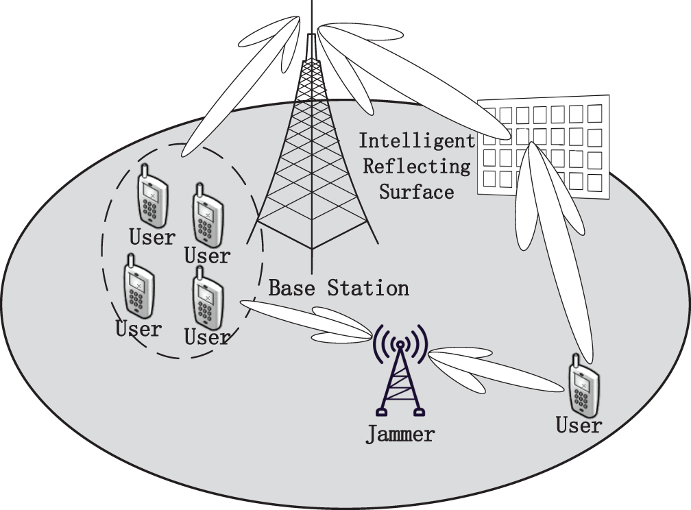
Figure 1: System model
The received signal from the relay is:
The signal transmitted by the relay node is:
The signal received by the relay node is normalized by the energy coefficient
The received SINR at the relay node is:
The signal received by the destination node is:
Among them,
The receiver’s SINR is:
3 Null Space Projection Beamforming
Most of the existing beamforming methods that can mitigate interference in massive MIMO systems require instantaneous channel state information, and instantaneous channel estimation in massive MIMO systems will bring high feedback overhead and hardware overhead to the system. NSP beamforming does not require instantaneous channel state information, but only needs the second-order statistics of the channel state information, including the signal covariance matrix and the interference covariance matrix. This method is more feasible when only statistical channel state information is available.
With the knowledge of the statistical CSI, NSP beamforming can be employed to mitigate the interference. The equivalent channel from the source node to the destination node is denoted as
To improve the receiver’s and the relay’s signal-to-noise ratio
Fig. 2 compares the SINR of the NSP Beamforming scheme and the scheme provided in [5] under different receiving SNRs. Under low SNR, the studied NSP Beamforming scheme is anti-jamming. The performance is significantly improved. When the receiving signal-to-noise ratio is −20 dB, the signal-to-interference noise ratio of the NSP Beamforming scheme in [5] is improved by 13 dB. The projected NSP Beamforming can also bring a minimum 6 dB improvement in anti-jamming performance.
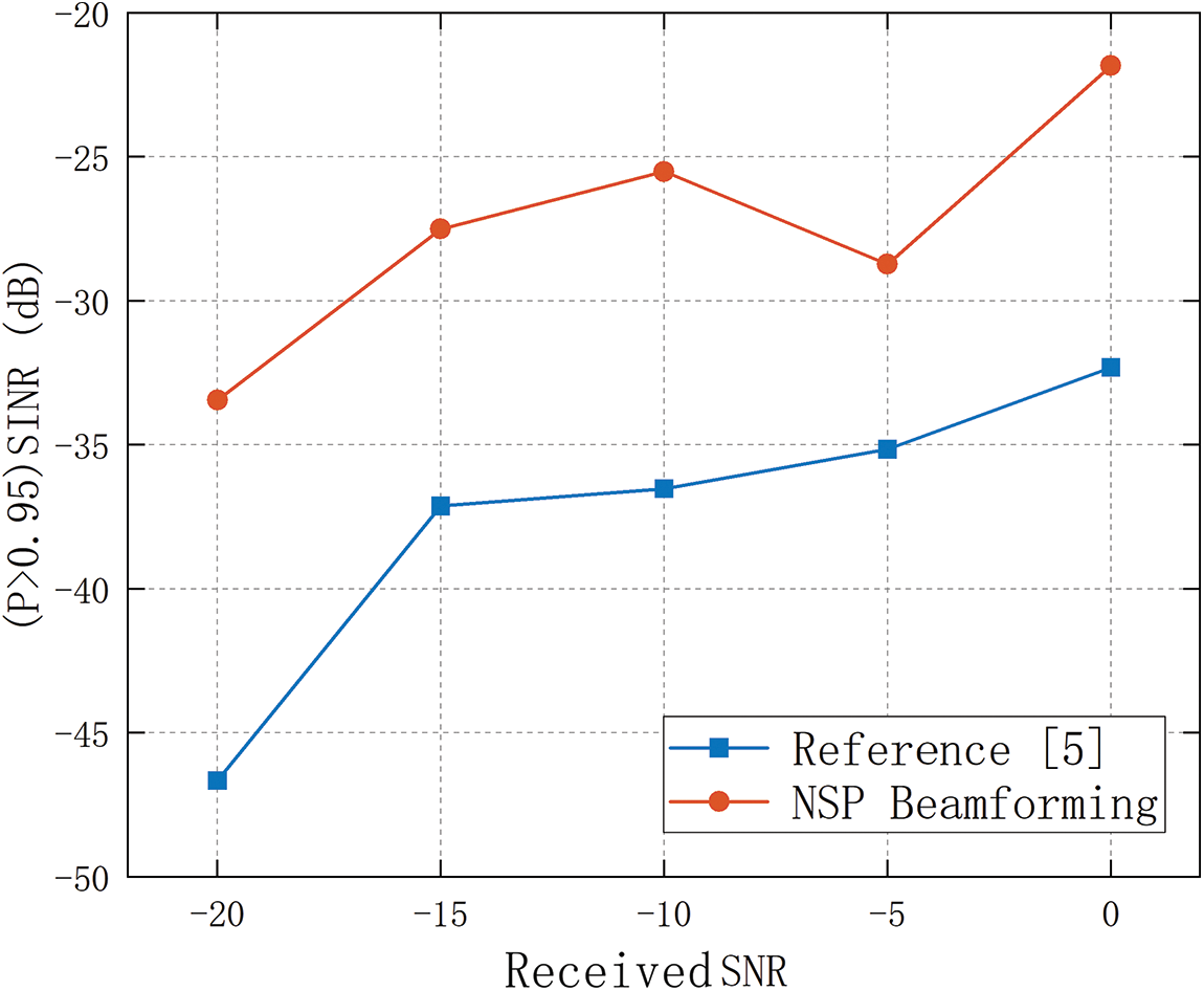
Figure 2: The receiver’s SINR (P > 0.95)
Fig. 3 shows the influence of the number of users in the cell on the received signal-to-interference and noise ratio of the base station. With the increase of the number of users in the cell, the received signal-to-interference and noise ratio of the base station continues to decrease. At this time, the base station needs to deal with external interference and multi-users in the cell at the same time. When the number of users increases, the performance of the NSP Beamforming scheme decreases slightly, and with the increase of the number of users in the cell, the scheme reported in [5] is more resistant to interference than the NSP Beamforming scheme. The performance gap of the interference beamforming scheme gradually increases. When the number of users is 10, the (P > 0.95) receive signal-to-interference-noise ratio of the NSP Beamforming beamforming scheme was improved by about 8 dB compared with the reference [5] scheme.
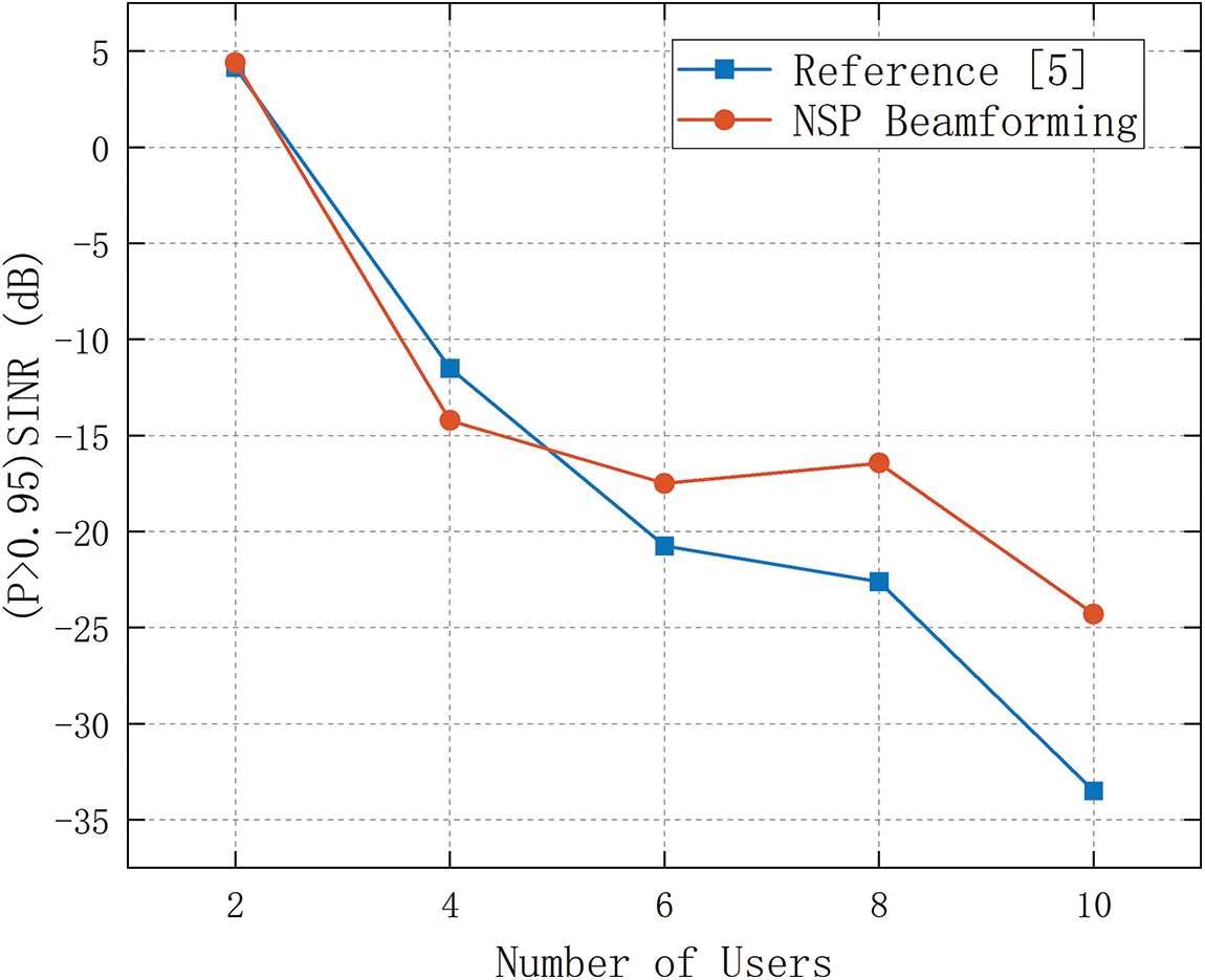
Figure 3: SINR vs. number of users
Fig. 4 compares the effect of the number of antennas on the receiving (P > 0.95) signal-to-interference-noise ratio between the NSP Beamforming scheme and the reference [5] scheme. With the increase of the number of antennas, the difference between the received signal-to-interference and noise ratio of the two schemes gradually decreases, but when the number of antennas is small, the NSP Beamforming scheme has obvious advantages. When the number of antennas is 49, the signal-to-interference-to-noise ratio of the NSP Beamforming scheme is about 13 dB higher than that of the reference [5] scheme. A smaller number of antennas is beneficial to control the complexity and power consumption of the system.
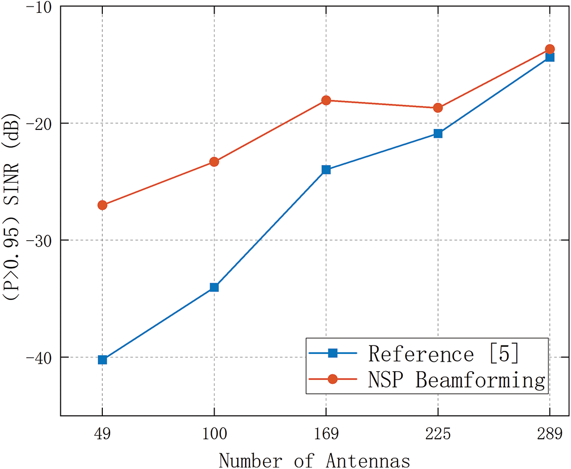
Figure 4: SINR vs. number of antennas
Fig. 5 describes the SINR cumulative distribution function of the NSP Beamforming scheme under different numbers of interference sources. In the simulation, the number of users in the cell is set to 10, the number of uniform rectangular antenna array antennas is 49, and the transmission power of the interference source and the base station is the same, the interference source is less than or equal to 300 m from the base station. When the number of interference sources increased, the signal space occupied by interference increased the available non-interference signal space decreased the signal transmission is limited, the SINR and CDF curves move to the left, and the system performance decreases.
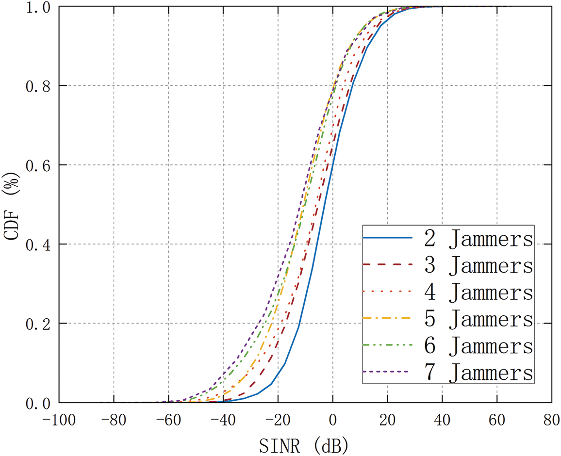
Figure 5: CDF with different number of jammers
Fig. 6 depicts the relationship between the number of antennas and the (P > 0.95) SNR of the NSP Beamforming scheme under different numbers of interference sources. In the simulation, the number of users in the cell is set to 10, and the antenna array type at the base station is Uniform rectangular antenna array, the interference source is the same as the base station transmit power, and the distance between the interference source and the base station is less than or equal to 300 m. When the number of antennas increases, the resolution of the azimuth and pitch angles of the signal and the interference by the antenna array of the base station is improved, the accuracy of the distribution estimation of the signal and the interference in the channel is improved, and the received signal-to-interference-noise ratio increases. When the number of interference sources is less than When there are 5, the base station receives the signal to interference and noise ratio increases approximately linearly with the increase of the number of antennas. When the number of interference sources is greater than or equal to 5, the signal space occupied by the interference is large, and the base station only uses the channel covariance matrix statistical information to estimate The null space of interference is difficult, and the signal-to-interference-noise ratio received by the base station increases approximately logarithmically with the increase of the number of antennas.
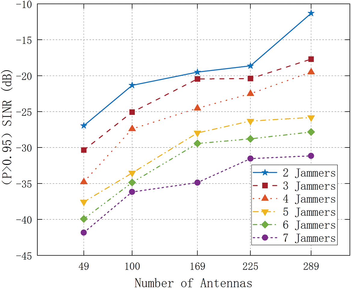
Figure 6: SINR (P > 0.95) with different number of antennas
Fig. 7 depicts the relationship between the number of users in the cell and the (P > 0.95) SINR under the NSP Beamforming scheme with different numbers of interference sources. In the simulation, the antenna array type at the base station is set to be a uniform rectangular antenna array, and the number of antennas is 49, the interference source and the base station have the same transmit power, and the distance between the interference source and the base station is less than or equal to 300 m. When the number of users in the cell increases, the multi-user interference increases, the interference null space of the signal decreases, and the received signal-to-interference-noise ratio decreases. When the number of interference sources is less than or equal to 5, the NSP Beamforming scheme can better separate the signal subspaces with less interference, and transmit information through the subspaces of these signals with less interference. When the number of sources is greater than 5, it is difficult for this scheme to separate the null space of interference using only secondary statistics.
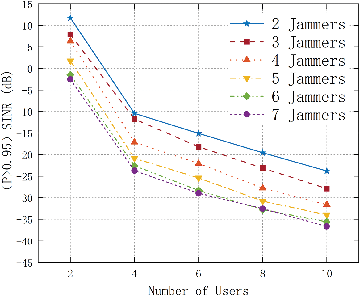
Figure 7: SINR (P > 0.95) with different number of users
In this paper, we consider a symbiotic radio anti-jamming system equipped with a multi-antenna system at the main base station, equipped with uniform rectangular array antennas at the base station, and adopting anti-jamming beamforming based on null-space projection. The IRS can assist in changing the beam angle to avoid opening the interference signal to improve the signal-to-interference-noise ratio of the received signal at the user. The simulation results show that the anti-jamming performance of the zero-space projection anti-jamming beamforming scheme is significantly improved, which can effectively improve the signal-to-noise ratio at the user in the case of directional interference. When the number of antennas increases, the azimuth and pitch of the base station antenna array to the signal and interference The resolution of the angle is improved, the accuracy of the distribution estimation of the signal and the interference in the channel is improved, the received signal-to-interference-noise ratio increases, and when the number of interference sources increases, the signal space occupied by the interference increases, the available space for non-interference signals decreases, and the signal transmission is limited. When the number of interference sources is less than or equal to 5, NSP Beamforming can better separate the signal subspace with less interference.
Acknowledgement: Many thanks for the resources andmaterials provided by the StateKey Laboratory of Complex Electromagnetic Environment Effects on Electronics and Information System (CEMEE), Longmen Laboratory, and Henan University of Science and Technology, and thank the teammembers for their support.
Funding Statement: This work was supported by the National Natural Science Foundation of China (62271192); Henan Provincial Scientists Studio (GZS2022015), Central Plains Talents Plan (ZYYCYU202012173); National Key R&D Program of China (2020YFB2008400); the Program of CEMEE (2022Z00202B); LAGEO of Chinese Academy of Sciences (LAGEO-2019-2); Program for Science & Technology Innovation Talents in the University of Henan Province (20HASTIT022); Natural Science Foundation of Henan under Grant 202300410126; Program for Innovative Research Team in University of Henan Province (21IRTSTHN015); Equipment Pre-Research Joint Research Program of Ministry of Education (8091B032129); Training Program for Young Scholar of Henan Province for Colleges and Universities (2020GGJS172); Program for Science & Technology Innovation Talents in Universities of Henan Province under Grand (22HASTIT020) and Henan Province Science Fund for Distinguished Young Scholars (222300420006).
Author Contributions: The authors confirm contribution to the paper as follows: study conception and design: Baofeng Ji, Yifan Liu; data collection: Baofeng Ji, Yifan Liu, Ling Xing; analysis and interpretation of results: Baofeng Ji, Yifan Liu, Tingpeng Li, Weixing Wang; draft manuscript preparation: Shahid Mumtaz, Xiaolong Shang, Wanying Liu, Congzheng Han. All authors reviewed the results and approved the final version of the manuscript.
Availability of Data and Materials: Due to team policies and confidentiality agreements, we cannot provide data. We have fully described the process of experimental design, analysis and results in the article, as well as data analysis and processing.
Conflicts of Interest: The authors declare that they have no conflicts of interest to report regarding the present study.
References
1. Hamamreh, J. M., Furqan, H. M., Arslan, H. (2019). Classifications and applications of physical layer security techniques for confidentiality: A comprehensive survey. IEEE Communications Surveys & Tutorials, 21(2), 1773–1828. [Google Scholar]
2. Sun, L., Tian, X. (2022). Physical layer security in multi-antenna cellular systems: Joint optimization of feedback rate and power allocation. IEEE Transactions on Wireless Communications, 21(9), 7165–7180. [Google Scholar]
3. Chen, X., Ng, D. W. K., Gerstacker, W. H., Chen, H. H. (2017). A survey on multiple-antenna techniques for physical layer security. IEEE Communications Surveys & Tutorials, 19(2), 1027–1053. [Google Scholar]
4. Wang, D., Bai, B., Zhao, W., Han, Z. (2019). A survey of optimization approaches for wireless physical layer security. IEEE Communications Surveys & Tutorials, 21(2), 1878–1911. [Google Scholar]
5. Yin, H., Gesbert, D., Filippou, M., Liu, Y. (2013). A coordinated approach to channel estimation in large-scale multiple-antenna systems. IEEE Journal on Selected Areas in Communications, 31(2), 264–273. [Google Scholar]
6. Chen, K., Yang, S., Chen, Y., Qu, S. W., Hu, J. (2021). Hybrid directional modulation and beamforming for physical layer security improvement through 4-D antenna arrays. IEEE Transactions on Antennas and Propagation, 69(9), 5903–5912. https://doi.org/10.1109/TAP.2021.3060056 [Google Scholar] [CrossRef]
7. Yaacoub, E., Al-Husseini, M., Chehab, A., Abualsaud, K., Khattab, T. et al. (2019). 3D beamforming with massive cylindrical arrays for physical layer secure data transmission. IEEE Communications Letters, 23(5), 830–833. [Google Scholar]
8. Xu, Z., Qu, A., An, K. (2021). Coalitional game based joint beamforming and power control for physical layer security enhancement in cognitive IoT networks. China Communications, 18(12), 139–150. [Google Scholar]
9. Chen, S., Sun, C. (2021). Relay beamforming design for physical layer secure communication via line search algorithm. China Communications, 18(12), 270–284. [Google Scholar]
10. Dong, R., Wang, B., Cao, K. (2021). Security enhancement of UAV swarm enabled relaying systems with joint beamforming and resource allocation. China Communications, 18(9), 71–87. [Google Scholar]
11. Liang, Y. C., Zhang, Q., Larsson, E. G., Li, G. Y. (2020). Symbiotic radio: Cognitive backscattering communications for future wireless networks. IEEE Transactions on Cognitive Communications and Networking, 6(4), 1242–1255. [Google Scholar]
12. Chen, H., Yang, G., Liang, Y. C. (2021). Joint active and passive beamforming for reconfigurable intelligent surface enhanced symbiotic radio system. IEEE Wireless Communications Letters, 10(5), 1056–1060. [Google Scholar]
13. Huang, W., Ding, W., Kai, C., Yi, Y., Huang, Y. (2022). Joint placement and beamforming design for IRS-enhanced multiuser MISO systems. IEEE Transactions on Communications, 70(10), 6678–6692. [Google Scholar]
14. Yang, H., Ye, Y., Liang, K., Chu, X. (2021). Energy efficiency maximization for symbiotic radio networks with multiple backscatter devices. IEEE Open Journal of the Communications Society, 2, 1431–1444. [Google Scholar]
15. Hua, M., Wu, Q., Yang, L., Schober, R., Poor, H. V. (2022). A novel wireless communication paradigm for intelligent reflecting surface based symbiotic radio systems. IEEE Transactions on Signal Processing, 70, 550–565. [Google Scholar]
16. Hua, M., Yang, L., Wu, Q., Pan, C., Li, C. et al. (2021). UAV-assisted intelligent reflecting surface symbiotic radio system. IEEE Transactions on Wireless Communications, 20(9), 5769–5785. [Google Scholar]
17. Hu, A. (2016). Statistical beamforming for interference mitigation in multi-cell massive MIMO systems. Frequenz, 70(1–2), 47–56. https://doi.org/10.1515/freq-2015-0074 [Google Scholar] [CrossRef]
Cite This Article
 Copyright © 2024 The Author(s). Published by Tech Science Press.
This work is licensed under a Creative Commons Attribution 4.0 International License , which permits unrestricted use, distribution, and reproduction in any medium, provided the original work is properly cited.
 Downloads
 Citation Tools