
 Submit a Paper
 Propose a Special lssue
 Open Access
ARTICLE

Overall Assessment of Heat Transfer for a Rarefied Flow in a Microchannel with Obstacles Using Lattice Boltzmann Method
1
Laboratory of Development in Mechanics and Materials (LDMM), Zian Achour University, Djelfa, PB 3117, Algeria
2
Department of Technology, University Center Salhi Ahmed Naama (Ctr. Univ. Naama), P. O. Box 66, Naama, 45000, Algeria
3
Department of Mechanical and Mechatronics Engineering Afe Babalola University, Ado Ekiti, 360101, Nigeria
4
Departement of Physics, Faculty of Science, Abou Bekr Belkaid University, Tlemcen, 13000, Algeria
5
Department of Physics, Faculty of Applied Sciences, Palestine Technical University-Kadoorie, Tulkarm, Palestine
6
Aeronautical Technical Engineering, Al-Farahidi University, Baghdad, 10011, Iraq
7
Mechanical Engineering Department, University of Kerbala, Karbala, 56001, Iraq
8
Information and Communication Technology Research Group, Scientific Research Center, Al-Ayen University, Thi-Qar, Iraq
9
National University of Science and Technology, Dhi Qar, Iraq
* Corresponding Author: Younes Menni. Email:
Computer Modeling in Engineering & Sciences 2024, 138(1), 273-299. https://doi.org/10.32604/cmes.2023.028951
Received 18 January 2023; Accepted 04 May 2023; Issue published 22 September 2023
 View Full Text
 Download PDF
Abstract
The objective of this investigation is to assess the effect of obstacles on numerical heat transfer and fluid flow momentum in a rectangular microchannel (MC). Two distinct configurations were studied: one without obstacles and the other with alternating obstacles placed on the upper and lower walls. The research utilized the thermal lattice Boltzmann method (LBM), which solves the energy and momentum equations of fluids with the BGK approximation, implemented in a Python coding environment. Temperature jump and slip velocity conditions were utilized in the simulation for the MC and extended to all obstacle boundaries. The study aims to analyze the rarefaction effect, with Knudsen numbers (Kn) of 0.012, 0.02, and 0.05. The outcomes indicate that rarefaction has a significant impact on the velocity and temperature distribution. The presence of nine obstacles led to slower fluid movement inside the microchannel MC, resulting in faster cooling at the outlet. In MCs with obstacles, the rarefaction effect plays a crucial role in decreasing the Nusselt number (Nu) and skin friction coefficient (Cf). Furthermore, the study demonstrated that the obstacles played a crucial role in boosting fluid flow and heat transfer in the MC. The findings suggest that the examined configurations could have potential applications as cooling technologies in micro-electro-mechanical systems and microdevice applications.Keywords
Nomenclature
| Density momentum distribution function | |
| Internal energy distribution function | |
| Lattice speed of sound ( | |
| Inlet temperature ( | |
| Wall temperature ( | |
| Inlet velocity ( | |
| Non-dimensional height of microchannel | |
| Non-dimensional length of microchannel | |
| Pressure | |
| Temperature jump coefficient | |
| Bulk temperature | |
| Thermal conductivity ( | |
| Knudsen number | |
| Reynolds number | |
| Prandtl number | |
| Nusselt number | |
| Non-dimensional parameter | |
| Internal energy | |
| Density ( | |
| Relaxation time for velocity | |
| Relaxation time for temperature | |
| Kinematic viscosity | |
| Thermal diffusivity ( | |
| Viscosity ( | |
| Weight factor | |
| Lattice Boltzmann method | |
| Thermal lattice Boltzmann method | |
| Bhatnagar, Gross, and Krook | |
| Lattice direction | |
| Equilibrium | |
| Position | |
| Time | |
| Inlet | |
| Outlet | |
| Wall |
Microfluidic devices have been developing rapidly in recent years, and have been increasing in several applications such as drug delivery and cell sorting. Microfluidic devices have advantages over traditional devices, such as low energy cost and separation efficiency [1]. In addition to parallel processing, low material usage, and energy efficiency [2]. Moreover, The control of flows [2] in microchannels (MCs) and heat transfer is considered a complex process [3] and is one of the most important research fields in microfluidics [4]. Microchannels have various implementations in several fields as the cooling technology for addressing heat dissipation issues obtained via high heat flux devices [5]. For example, MC heat sinks are considered cutting-edge cooling technology for electronic systems according to their height of heat generation [6]. The heat transfer mechanism differs from the micro size to the macro size.
The Knudsen number (Kn), which is defined as the ratio of the particle mean free path to the characteristic length of the flow, serves as an indicator of the rarefaction effect [7]. The Kn number provides a way to categorize fluid flows in the micro-scale into four distinct regimes, each with unique characteristics. These regimes are classified as: continuum flow (for Kn numbers below 0.001), slip flow (for Kn numbers between 0.001 and 0.1), transition flow (for Kn numbers between 0.1 and 10), and free-molecular flow (for Kn numbers greater than 10). This categorization is based on the relative importance of viscous and molecular forces in determining the behavior of the fluid. The Kn number serves as a useful tool for predicting the regime of fluid flow and designing systems that operate in specific flow regimes [8,9].
In microflows, the slip boundary plays a critical role and cannot be neglected when analyzing the fluid’s flow and thermal behaviors [10,11]. The lattice Boltzmann method (LBM) can be used in microfluidics as an important computational tool [12,13]. According to the high level of parallel ability and the simple algorithm formulation [14], particularly the explicit formulation. The LBM method shows excellent implementation [15] as well as can handle complex boundary conditions [6]. Furthermore, the thermal LBM has been acknowledged as a powerful technique for investigating MC flows that incorporate slip boundary conditions [16]. The LBM method includes two steps collision and streaming [13]. Various models of LBM have been developed to increase the performance of the thermal field simulation. One approach that has been proposed for modeling microscale flows is the double population method, which involves the use of two distinct distribution functions. Specifically, this approach utilizes a density-momentum distribution function for the fluid domain and an internal energy distribution function for the thermal field [11,17].
Numerous studies have investigated the behavior of heat transfer and fluid flow in MCs utilizing the thermal LBM while taking into account slip velocity and temperature jump. For instance, Niu et al. [18] used the thermal LBM to simulate microthermal flow with velocity slip and temperature jump. Similarly, Liu et al. [19] investigated gas flow in a long MC with the LBM and examined the effects of slip and transition flow. Their results showed that the rarefaction effect becomes increasingly significant as the Kn number increases. Hatam et al. [20] studied Cu-H2O heat transfer in a MC heat sink and demonstrated that increasing the interactions ‘nanoparticles-solid phase’ leads to an increase in channel aspect ratio, resulting in an elevated Nusselt number. Finally, Ghadirzadeh et al. [21] utilized the LBM to simulate laminar nanofluid flows within an annular MC in a slip flow regime. These studies provide valuable insights into the behavior of fluids in MCs under various conditions and have advanced our understanding of the mechanisms governing heat transfer and fluid flow in these systems.
Knupp et al. [22] analyzed slip flow in laminar gaseous flow with heat transfer in circular MCs. The study found a decrease in Nu numbers as the Kn number increased. Ahangar et al. [23] used LBM to investigate slip and transient flow regimes in MCs. The study found that in the slip regime, the velocity increased with the Kn number at the center and at the exit of the MC in the transient regime. Alipour Lalami et al. [24] employed LBM with slip boundary and temperature jump to examine heat transfer of nanofluids at conjugate heat in a wide MC with a thick wall. The study found that higher Re values caused an increase in the average Nu number on superhydrophobic surfaces. Finally, Rehman et al. [25] investigated fluid flow in a rectangular channel with a partially heated region by a circular, heated cylinder placed between channels as an obstacle. The study considered four different cases where rectangular ribs were installed and found that the circular obstacle showed the highest drag force when rectangular ribs were present on both the lower and upper walls heated.
Ashraf et al. [26] investigated the behavior of an oscillating mixed convection flow over a horizontal circular cylinder. The study revealed that buoyancy forces play a significant role in accelerating the fluid flow and increasing the velocity of fluid particles. Qiu et al. [27] examined the heat dissipation model of a copper MC heat sink, considering the impact of the Nu number on heat transfer. Their results indicated that the Nu number is a crucial factor affecting the heat transfer performance. Ma et al. [28] simulated 3D laminar flow in a rectangular MC and found that low Re numbers can considerably influence the local Nu numbers in the thermal zone. Overall, these studies provide insights into the complex nature of heat transfer and fluid flow in MCs, highlighting the importance of considering various factors such as buoyancy forces, Nu number, and Re number for achieving optimal heat transfer performance.
In recent years, improving the heat transfer in microdevices has become a significant area of research, especially with the rapid advancement of Micro Electro Mechanical Systems (MEMS) [12,13]. The demand for more efficient designs and technologies to enhance heat transfer efficiency in heat transfer systems has also increased. Slip velocity conditions and temperature jump implementation are some of the methods that have been explored. The Lattice Boltzmann Method (LBM) has been recognized as a useful method to simulate microflow due to its mesoscale characteristics [14]. LBM has several attractive features, including superior representation of microscopic interactions. The most recent and useful LBM framework for dealing with thermal flows is the thermal lattice Boltzmann method with a double distribution function [17]. In the literature, various studies have been conducted on microscale heat transfer, such as Ashraf et al. [29], who examined the impact of variable surface temperature on periodic mixed convection using a thermally and electrically conducting cone in a porous medium. The study by Lori et al. [30] investigated the heat transfer and fluid flow in solid ribs and alternating vertical porous with microchannel heat sinks, showing that the average Nusselt number of the porous-rib microchannel was more significant than the solid case. Another study by Lobasov et al. [4] explored the influence of temperature jump and velocity slip on heat transfer in the microchannel and found that the heat flux density and average heat transfer coefficient increased as the slip length increased.
In the study by Ashraf et al. [29], the impact of variable surface temperature on periodic mixed convection was analyzed through the use of a thermally and electrically conducting cone positioned in a porous medium. The results indicated that there was an increase in temperature distribution as the Pr number values rose. Meanwhile, Lori et al. [30] explored heat transfer and fluid flow in solid ribs and porous material that alternated vertically with MC heat sinks. According to their findings, the average Nu number was greater in the porous-rib MC than in the solid case. Lastly, Lobasov et al. [4] focused on investigating the effects of temperature jump and velocity slip on heat transfer in a MC. Their research revealed that the heat flux density and average heat transfer coefficient increased with an increase in slip length. These three studies provide important insights into the diverse factors that can impact heat transfer in different systems.
Microdevices have witnessed significant advancements in recent times, with Micro Electro Mechanical Systems (MEMS) driving a lot of innovation [12,13]. However, there is a pressing need for more efficient and better-designed heat transfer systems to improve heat transfer in microdevices [31]. Two crucial factors that can impact the performance of such systems are the slip velocity condition and temperature jump implementation. A promising approach that has gained considerable attention in this context is the LBM, which offers superior representation of microscopic interactions [32]. Of all the LBM frameworks available, the thermal LBM with a double distribution function [17] is the most recent and useful for simulating microflows owing to its mesoscale characteristics [14]. LBM has demonstrated its superiority in modeling rarefied gas flow in microchannels [8]. These observations highlight the potential of LBM in enhancing heat transfer in microdevices and the need for further research in this area.
The present study aims to provide a numerical investigation of laminar fluid flow and forced convective heat transfer in a rectangular MC, both with and without obstacles placed on the walls. To conduct this study, we employed the thermal LBM with the BGK model, while implementing slip velocity and temperature jump on both the walls and the obstacles. The novelty of this study lies in its focus on the impact of obstacles present in the MC walls and how they can enhance fluid flow and heat transfer. Additionally, the study examines the application of thermal LBM with slip velocity and temperature jump on MC and obstacle walls. To this end, the MC was simulated with different obstacle positions, and the effects of the Kn number, the implementation of obstacles on fluid flow and heat transfer, and the Nu number in the MC were analyzed. The results of this study hold significant implications for the design of more efficient microfluidic devices with enhanced heat transfer.
2 Mathematical Modelling and Numerical Methods
In the present numerical investigations, the laminar fluid flow through the 2D rectangular MCs without and with alternating obstacles is studied with the LBM to analyze the convection heat transfer and fluid flow. A unit length


Figure 1: MC configurations with (a) no, (b) three, (c) nine obstacles
The microscale level presents unique challenges for computational fluid dynamics (CFD) techniques. The lattice Boltzmann method (LBM) has emerged as a promising alternative due to its simplicity and ability to handle complex microstructures [10]. In particular, the thermal lattice Boltzmann method (TLBM) has gained traction in heat transfer and fluid flow problems owing to its recent establishment and several potential applications [33]. The double distribution function approach, which uses two distribution functions to represent the velocity and temperature fields, respectively, is particularly useful in this context [15,34]. This study employs the TLBM with a double distribution function and BGK model to investigate fluid flow and temperature. The mathematical formalism is represented by the discrete Eqs. (1) and (2) [12]. The use of TLBM in this study highlights its potential for enhancing heat transfer and fluid flow in microscale systems, and its mathematical formalism opens up avenues for further research in this area.
In this study, we utilize a lattice model represented by a two-dimensional D2Q9 lattice connected by eight links, as depicted in Fig. 2. This lattice model serves as the foundation for our analysis and enables us to investigate the phenomena of interest accurately. By employing this specific lattice model, we can examine the behavior of the system in a controlled and precise manner, which is essential for drawing meaningful conclusions from our research.

Figure 2:
The equilibrium distribution functions of
We can express the discrete velocity vector for the D2Q9 lattice, which consists of a stationary central node connected to eight neighboring nodes in space, as follows:
In the
By utilizing the distribution function, we can calculate various macroscopic quantities, such as density, velocity, and temperature. These quantities are crucial in describing the behavior of the system under study and provide valuable insights into the underlying physical processes. The ability to calculate these macroscopic quantities accurately and efficiently from the distribution function is a significant advantage of this approach and allows us to gain a better understanding of the system’s dynamics.
The pressure can be directly obtained from the density and sound speed of the lattice
One can establish a relationship between the relaxation time and the kinematic viscosity (ν) and thermal diffusivity (α). These two physical quantities play a crucial role in characterizing the dynamics of the system under study.
2.3.1 Flow Boundary Conditions
The velocity is known at the inlet boundary but must be determined the density. The corrections performed by [36] were used to determine inlet density and unknown distribution functions:
The outlet velocity is unknown. Extrapolation is commonly utilized to obtain the unknown distribution functions at the east boundary [33], as shown by the Eqs. (16)–(18):
Fluid velocity near the wall differs from wall speed. The slip boundary condition for the bottom wall is given by the Eqs. (19)–(23) [21]:
After the fluid’s velocity on the microchannel wall, the speeds of the first two network nodes are
2.3.2 Temperature Boundary Conditions
The inlet temperature is given by [10] as:
An extrapolation can be used to obtain the outlet boundary condition for temperature [28]:
Tian et al. [35] described a temperature jump boundary condition for the top wall as:
Temperature jumps for the bottom wall are defined by the Eqs. (39)–(42):
The Number is expressed as [12]:
The local friction coefficient is determined by the equation:
Table 1 represents the mesh independency study at

2.5 Numerical Method and Validation
The present study was achieved under a python code environment to simulate heat transfer and fluid flow in a MC. The results were compared with those [12]. Velocity and temperature have without obstacles. From Fig. 3, the results show a good agreement.

Figure 3: Comparison of temperature and velocity profiles for
The Nusselt number also shows a suitable agreement with various
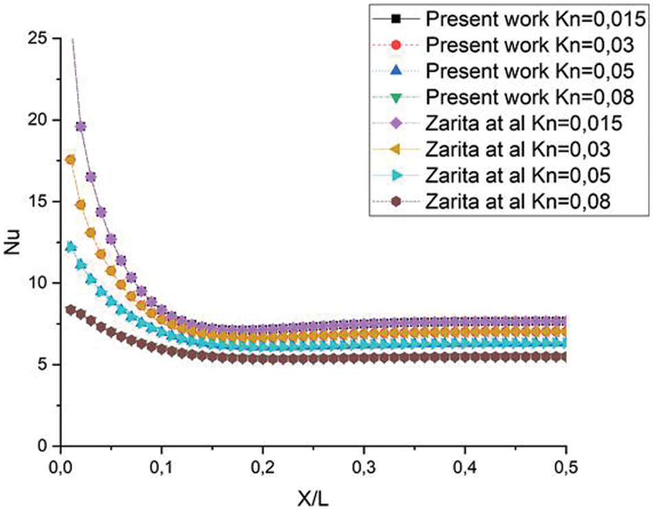
Figure 4: Comparison of Nusselt number for different
Figs. 5–7 represent the MC’s velocity distribution for
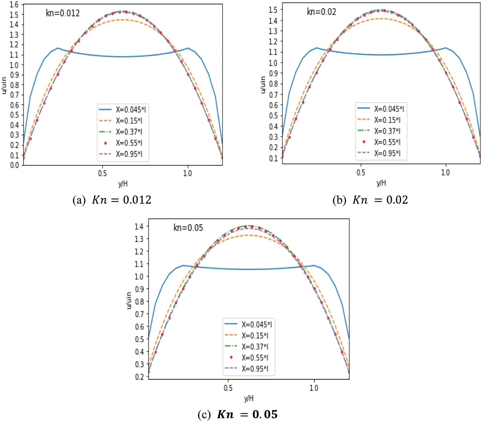
Figure 5: Velocity without obstacles for different
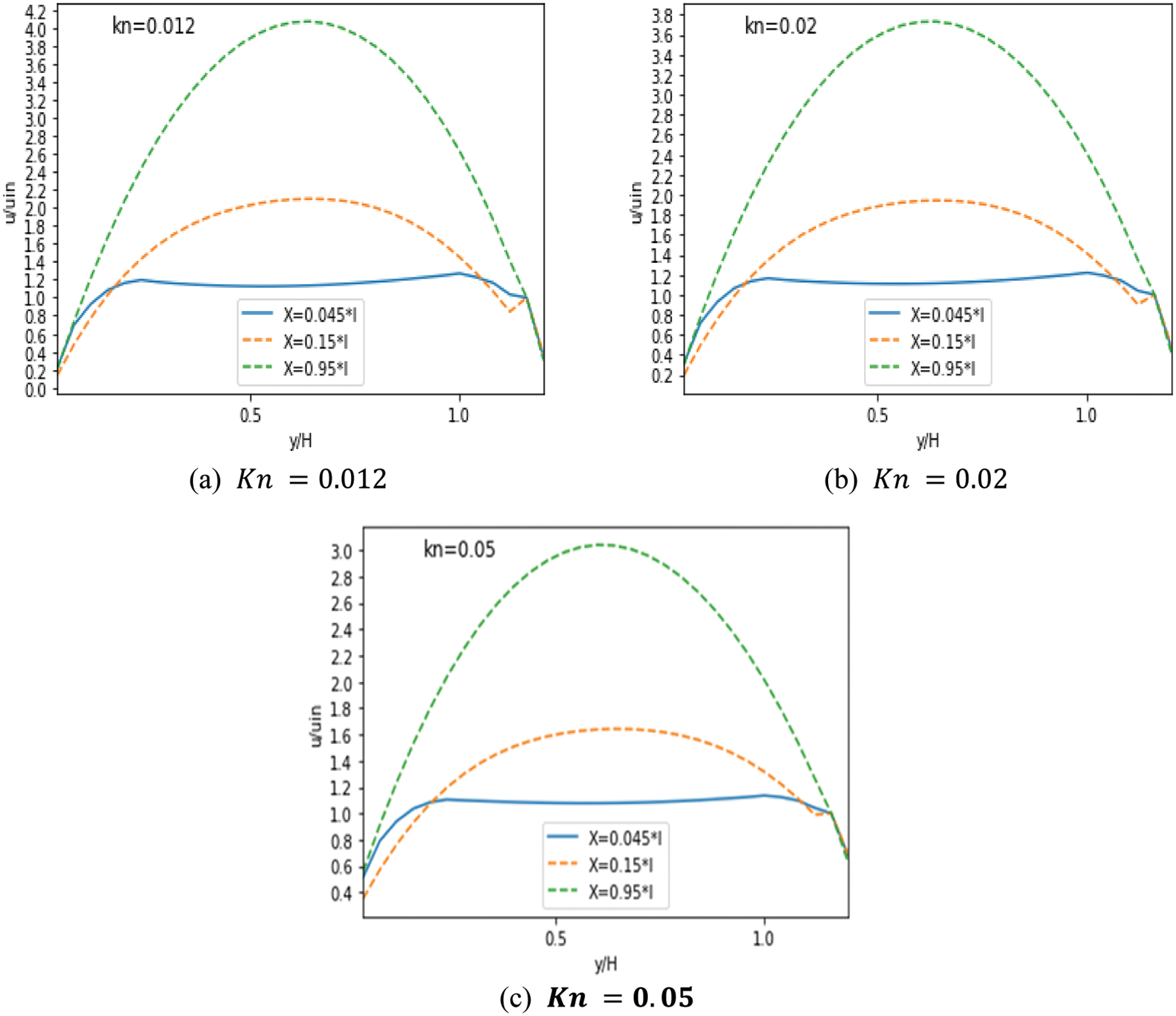
Figure 6: Velocity with three obstacles for different
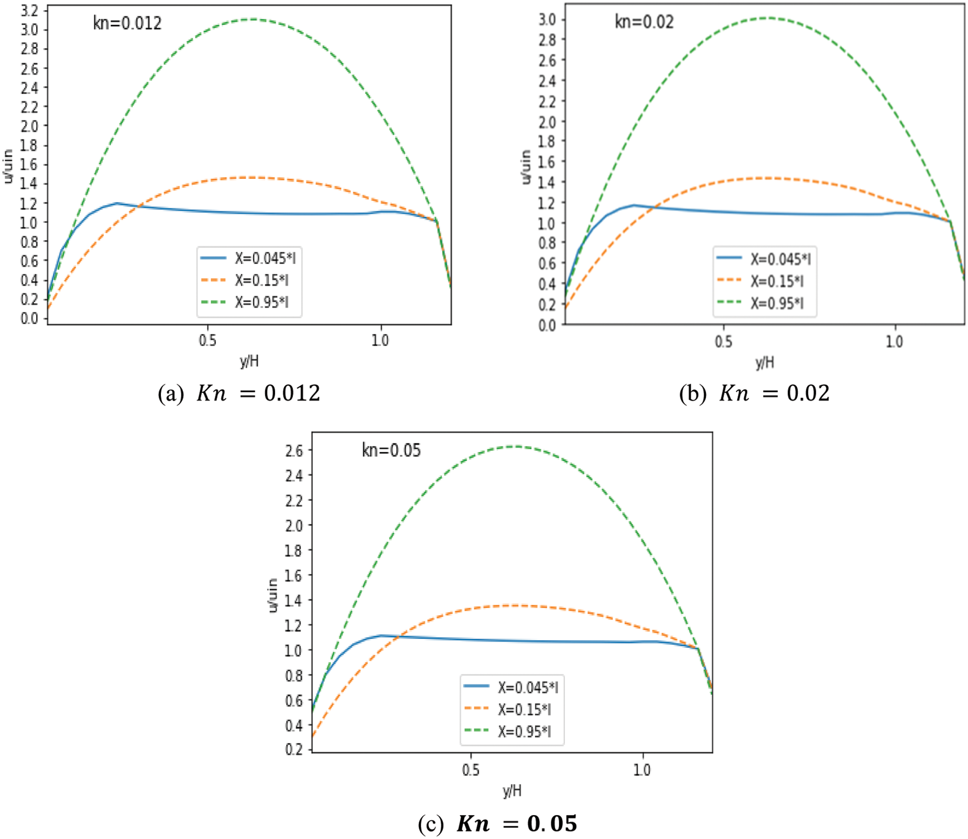
Figure 7: Velocity with nine obstacles for different
Fig. 8 shows the velocity streamlines in various cases with
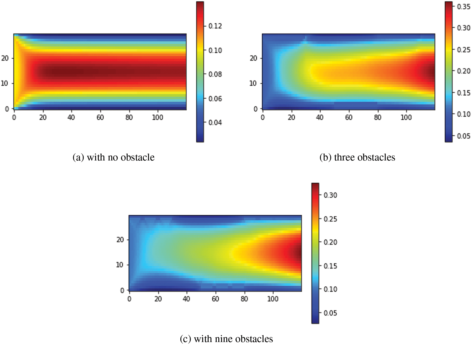
Figure 8: Velocity streamlines for
Fig. 9 illustrates the velocity contours for different cases with
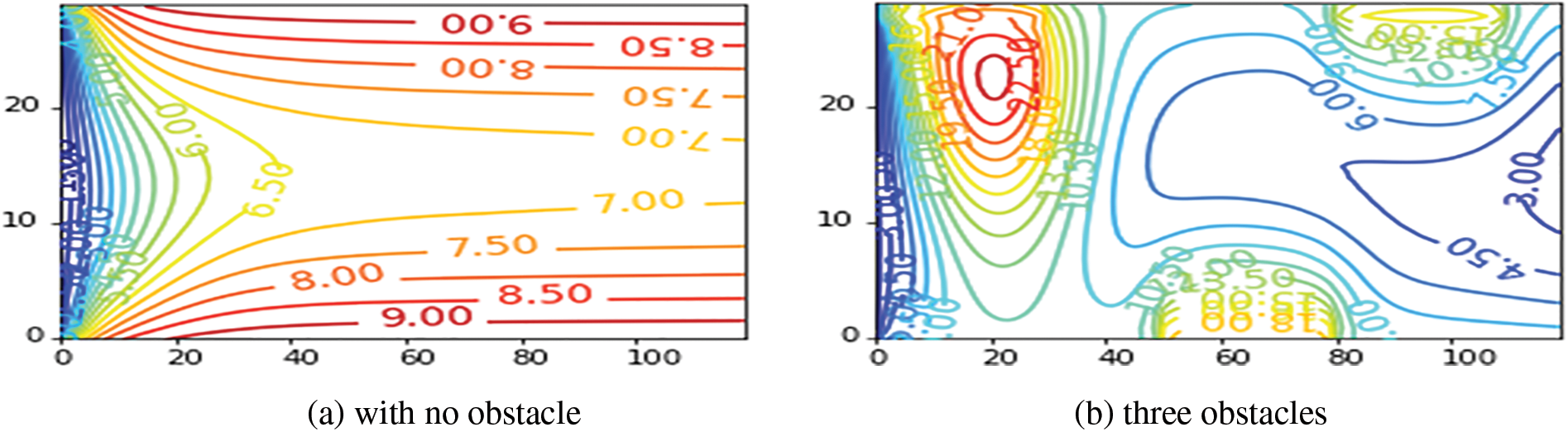

Figure 9: Velocity contours for
Figs. 10–12 depict the distribution of temperature along MC for three scenarios with
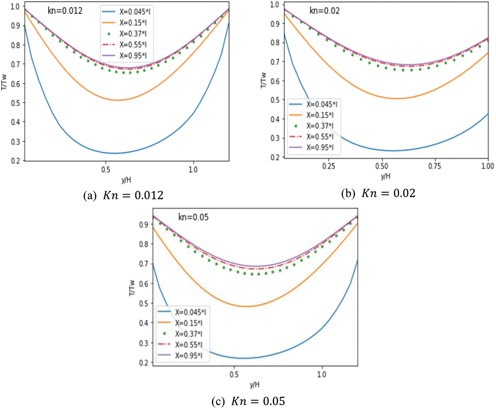
Figure 10: Evolution of the
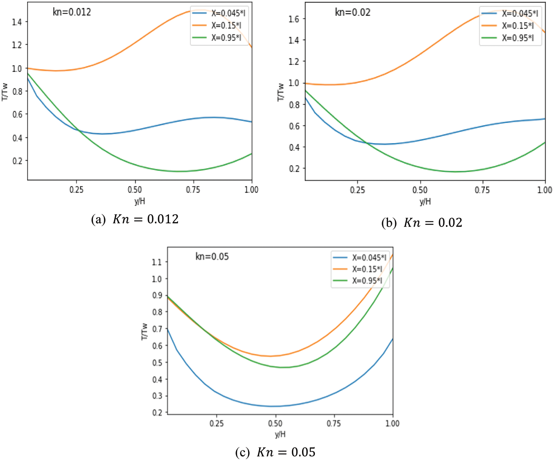
Figure 11: Evolution of the temperature according to different
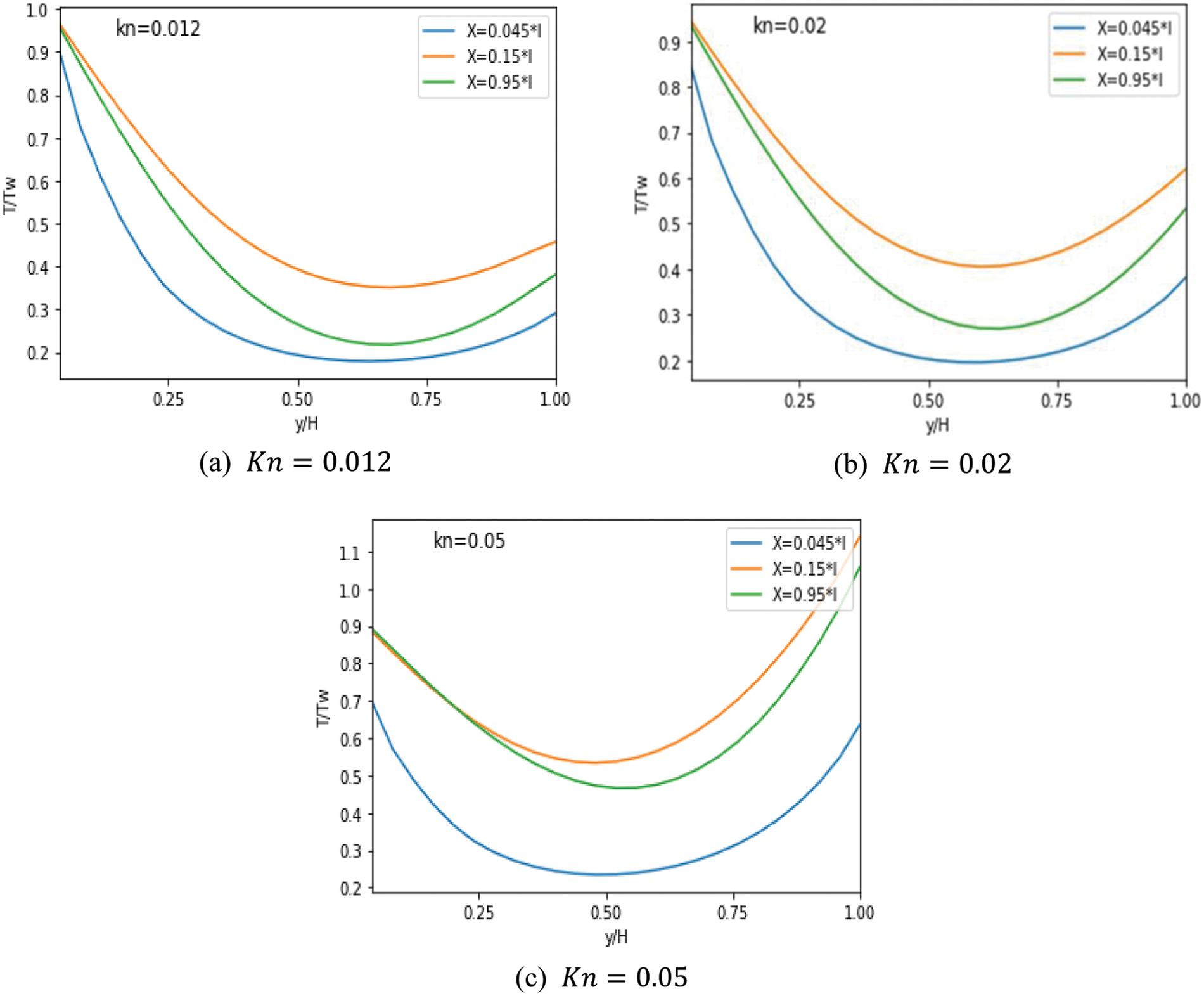
Figure 12: Evolution of the temperature according to different
Even when adding obstacles, the temperature continues to drop. The temperature reduction is noticeable when nine obstacles are added, as seen in Figs. 12a and 12b, respectively. Moreover, the impact of rarefaction in the central area is more prominent compared to the region near the wall. This is attributed to the substantial temperature difference observed near the wall, which is caused by the rapid establishment of the hydrodynamic and thermal boundary layers in the entrance area, as depicted in Fig. 12. To sum it up, the MC with obstacles exhibits superior heat transfer enhancement in comparison to a smooth MC.
From the streamlined Fig. 13, the temperature decreases rapidly from the wall to the neighboring layers, reaching a low value in the central region of the MC with no obstacles case, Fig. 13a. In the second case, Fig. 13b, the temperature near the first obstacle decreases slowly compared with other obstacles. But in the case with nine obstacles, the fluid flows quickly, as confirmed by the temperature profile, Fig. 13c. However, when compared to the scenario without obstacles, the inclusion of obstacles results in fluctuations in the temperature of the fluid at the wall and its adjacent layers. Furthermore, it leads to an increase in temperature in the central area of the MC.
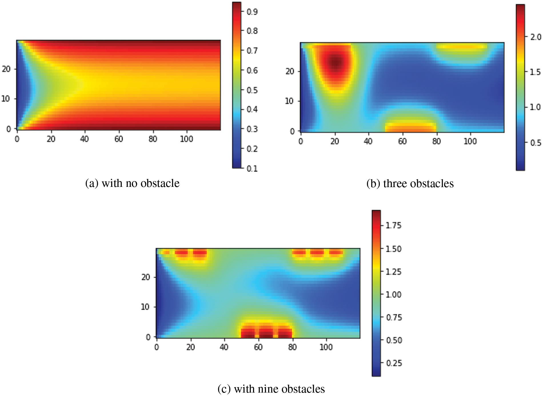
Figure 13: Functions of temperature streamlines for
To illustrate the heat transfer improvement mechanism by obstacles, the temperature contour was added to the study. Fig. 14 depicts the temperature contours for
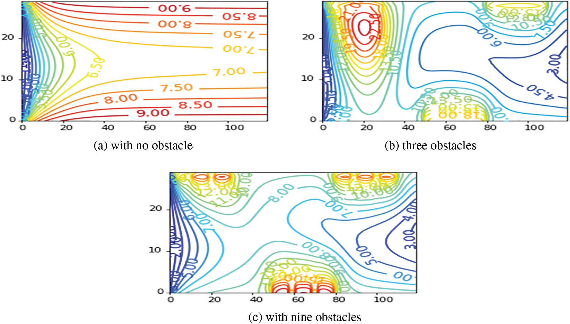
Figure 14: Temperature contours for
The evolution of the
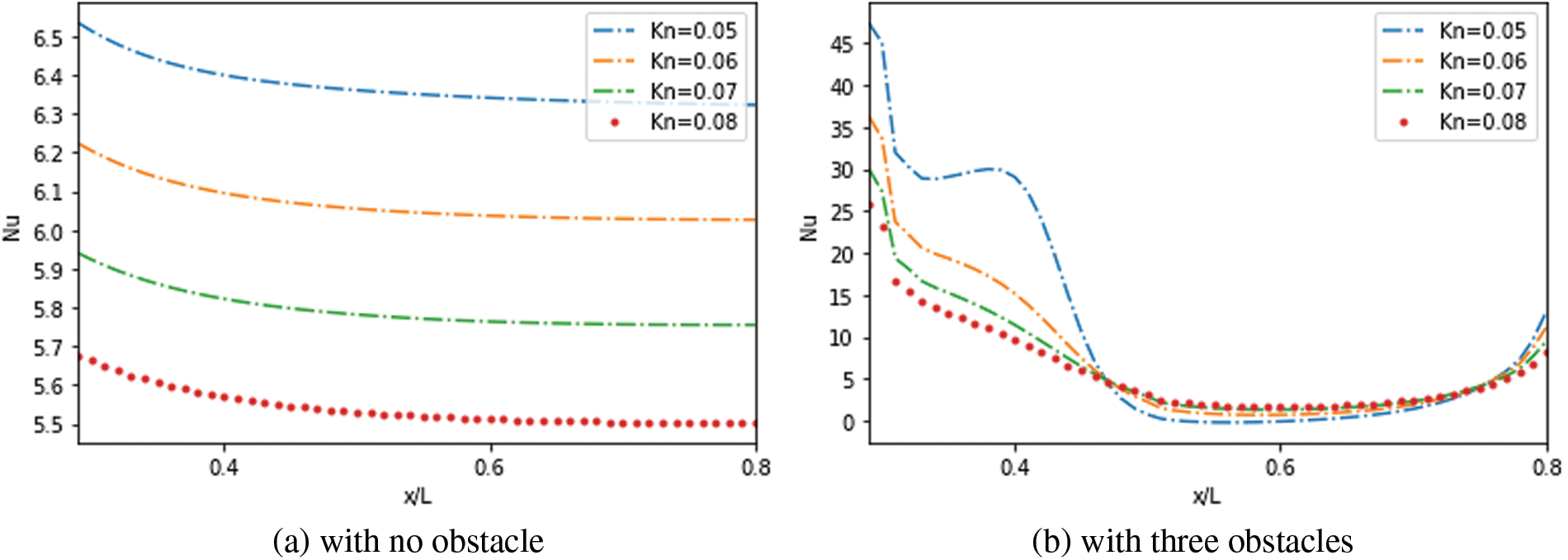
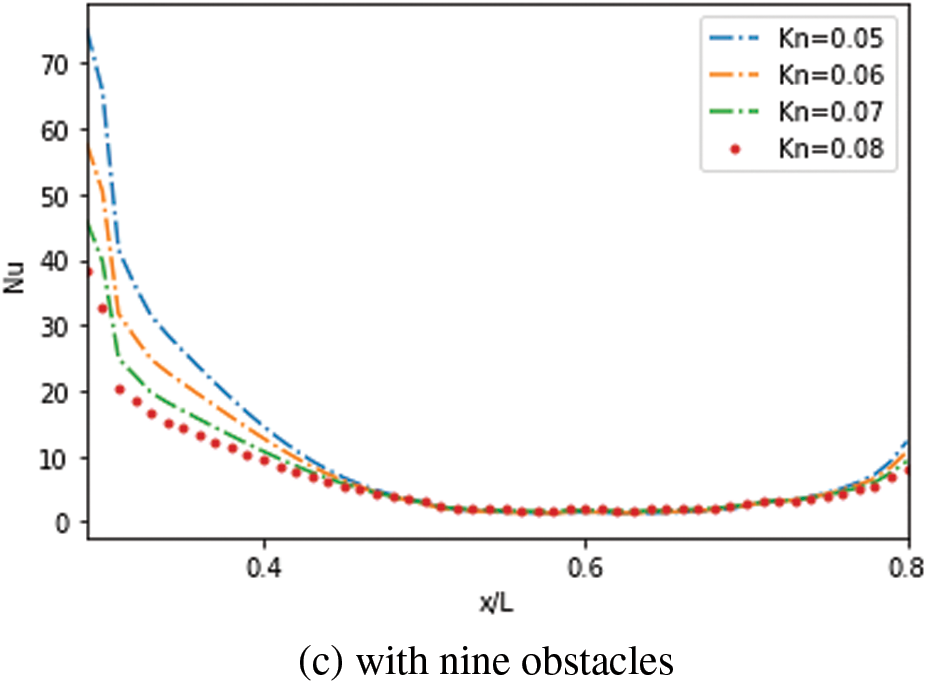
Figure 15: Effect of
Furthermore, due to the temperature gradient at the entrance region, the highest values were reached in the second case compared to the third one. The
Fig. 16 due to the rapid increase in velocity at the entrance zone and the reduction in the velocity gradient, the results showed a decreasing skin friction coefficient with a rise in


Figure 16: Effect of
Figs. 17 to 19 illustrate the axial variation of velocity slip along the lower and upper wall for various
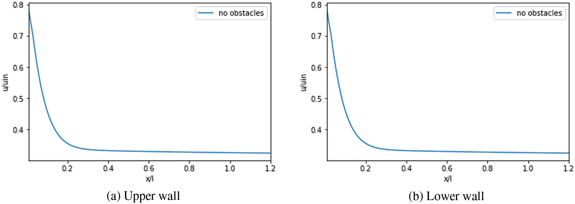
Figure 17: Velocity slip: Case without obstacles
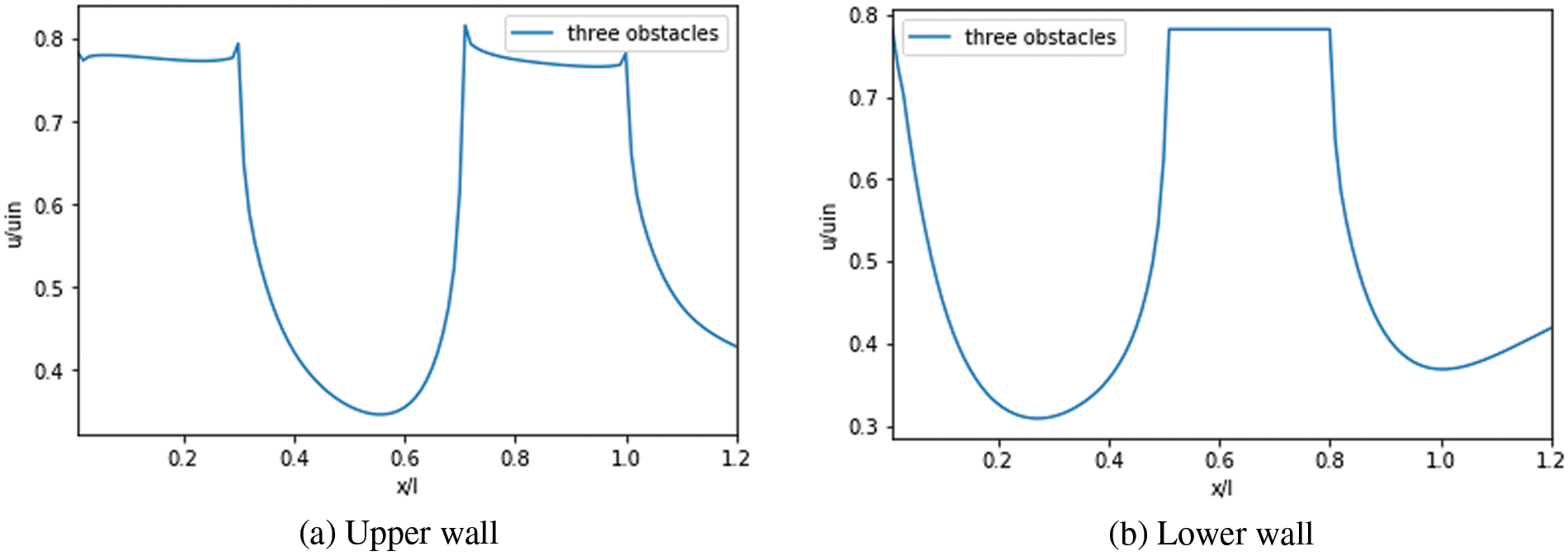
Figure 18: Velocity slip: Case with three obstacles
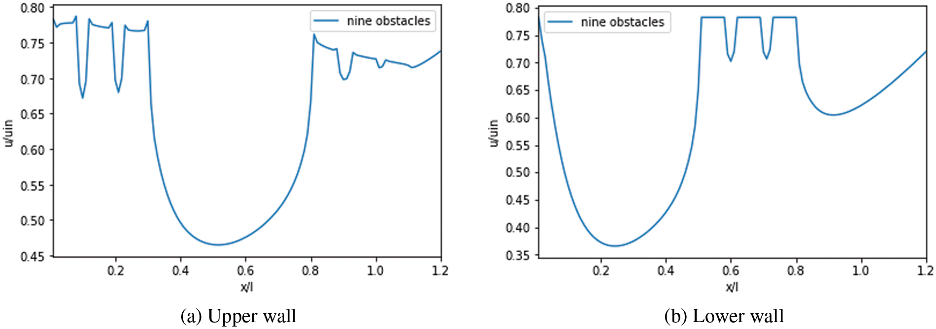
Figure 19: Velocity slip: Case with nine obstacles
Figs. 20 to 22 depict the temperature jump along the upper and lower walls of the MC in the function of
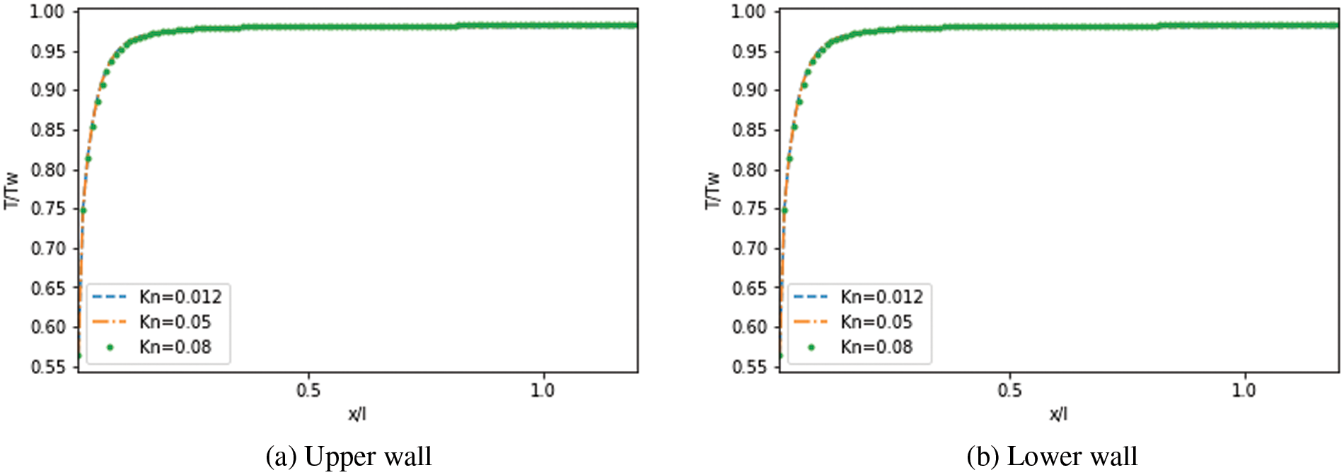
Figure 20: Effect of
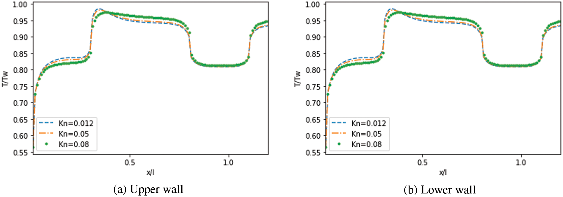
Figure 21: Effect of

Figure 22: Effect of
The BGK model-based TLBM was employed using Python computing code to investigate forced convective heat and fluid flow in a unit length of a rectangular MC under three different configurations. The first configuration was without obstacles, while the second and third configurations featured three and nine obstacles, respectively. The temperature jump and slip velocity were considered at the boundary and extended to the obstacle level. This numerical investigation included an analysis of the impacts of temperature jump and velocity slip on heat transfer, temperature, and velocity profile, as well as the rarefaction effect’s influence. The results showed the rarefaction effect’s significance on velocity and temperature distribution. The current TLBM with a DDF allowed the modeling of MCs with and without obstacles with slip velocity and temperature jump. The study found that the fluid moved slowly through the third microchannel configuration (with nine obstacles) and accelerated at the MC outlet, as indicated by the lower temperature profile. No vortex was captured, but the results highlighted the critical role played by obstacles in MCs. Additionally, the rarefaction effect played a significant role in reducing the
Acknowledgement: The authors express their appreciation to the General Directorate of Scientific Research and Technological Development (DGRSDT) of the Ministry of Higher Education and Scientific Research in Algeria.
Funding Statement: The authors received no specific funding for this study.
Author Contributions: The authors confirm contribution to the paper as follows: study conception: S. Hammid; study design: K. Naima; data collection: C. Kezrane; analysis and interpretation of results: K. Naima and A. Liazid; draft manuscript preparation: S. Hammid, K. Naima and Y. Menni; writing-review and editing: O.M. Ikumapayi, J. Asad, M.H. Rahman, F.L. Rashid, N.A. Hussien and Y. Menni. All authors reviewed the results and approved the final version of the manuscript.
Availability of Data and Materials: The data that support the findings of this study are available on request from the corresponding author.
Conflicts of Interest: The authors declare that they have no conflicts of interest to report regarding the present study.
References
1. Mondal, B., Mehta, S. K., Pati, S., Patowari, P. K. (2021). Numerical analysis of electroosmotic mixing in a heterogeneous charged micromixer with obstacles. Chemical Engineering and Processing-Process Intensification, 168(432), 108585. [Google Scholar]
2. Rehman, K. U., Al-Mdallal, Q. M., Sherif, E. S. M., Junaedi, H., Lv, Y. P. (2021). Numerical study of low Reynolds hybrid discretized convergent-divergent (CD) channel rooted with obstructions in left/right vicinity of CD throat. Results in Physics, 24(2), 104141. [Google Scholar]
3. Ullah, Z., Ashraf, M., Sarris, I. E., Karakasidis, T. E. (2022). The impact of reduced gravity on oscillatory mixed convective heat transfer around a non-conducting heated circular cylinder. Applied Sciences, 12(10), 5081. [Google Scholar]
4. Lobasov, A. S., Minakov, A. V., Rudyak, V. Y. (2022). The investigation of the velocity slip and the temperature jump effect on the heat transfer characteristics in a microchannel. Case Studies in Thermal Engineering, 31(1), 101791. [Google Scholar]
5. Sun, L., Li, J., Xu, H., Ma, J., Peng, H. (2022). Numerical study on heat transfer and flow characteristics of novel microchannel heat sinks. International Journal of Thermal Sciences, 176(5), 107535. [Google Scholar]
6. Gao, J., Hu, Z., Yang, Q., Liang, X., Wu, H. (2022). Fluid flow and heat transfer in microchannel heat sinks: Modelling review and recent progress. Thermal Science and Engineering Progress, 29(2), 101203. [Google Scholar]
7. Xu, L., Yu, X., Regenauer-Lieb, K. (2020). An immersed boundary-lattice Boltzmann method for gaseous slip flow. Physics of Fluids, 32(1), 012002. [Google Scholar]
8. Yuan, Y., Rahman, S. (2016). Extended application of lattice Boltzmann method to rarefied gas flow in micro-channels. Physica A: Statistical Mechanics and its Applications, 463(4), 25–36. [Google Scholar]
9. Ahangar, E. K., Izanlu, M., Jabbari, M., Ahmadi, G., Karimipour, A. (2020). Thermal microscale gas flow simulation using wall function and bounce-back scheme: Modified lattice Boltzmann method. International Communications in Heat and Mass Transfer, 119(4), 104993. [Google Scholar]
10. Zhang, Y., Xie, G., Karimipour, A. (2020). Comprehensive analysis on the effect of asymmetric heat fluxes on microchannel slip flow and heat transfer via a lattice Boltzmann method. International Communications in Heat and Mass Transfer, 118, 104856. [Google Scholar]
11. D’Orazio, A., Karimipour, A. (2019). A useful case study to develop lattice Boltzmann method performance: Gravity effects on slip velocity and temperature profiles of an air flow inside a microchannel under a constant heat flux boundary condition. International Journal of Heat and Mass Transfer, 136(1), 1017–1029. [Google Scholar]
12. Zarita, R., Hachemi, M. (2018). Numerical investigation and analysis of heat transfer enhancement in a microchannel using nanofluids by the lattice Boltzmann method. Frontiers in Heat and Mass Transfer, 12(5), 1–12. [Google Scholar]
13. Javaherdeh, K., Karimi, H., Azarbarzin, T. (2021). Lattice Boltzmann simulation of fluid flow and heat transfer in a micro channel with heat sources located on the walls. Superlattices and Microstructures, 160(3), 107069. [Google Scholar]
14. Wang, K., Chai, Z., Hou, G., Chen, W., Xu, S. (2018). Slip boundary condition for lattice Boltzmann modeling of liquid flows. Computers & Fluids, 161(5), 60–73. [Google Scholar]
15. Li, L., Mei, R., Klausner, J. F. (2013). Boundary conditions for thermal lattice Boltzmann equation method. Journal of Computational Physics, 237, 366–395. [Google Scholar]
16. Yang, L., Yu, Y., Pei, H., Gao, Y., Hou, G. (2019). Lattice Boltzmann simulations of liquid flows in microchannel with an improved slip boundary condition. Chemical Engineering Science, 202(9), 105–117. [Google Scholar]
17. Sharma, K. V., Straka, R., Tavares, F. W. (2020). Current status of lattice Boltzmann methods applied to aerodynamic, aeroacoustic, and thermal flows. Progress in Aerospace Sciences, 115, 100616. [Google Scholar]
18. Niu, X. D., Shu, C., Chew, Y. T. (2007). A thermal lattice Boltzmann model with diffuse scattering boundary condition for micro thermal flows. Computers & Fluids, 36(2), 273–281. [Google Scholar]
19. Liu, X., Guo, Z. (2013). A lattice Boltzmann study of gas flows in a long micro-channel. Computers & Mathematics with Applications, 65(2), 186–193. [Google Scholar]
20. Hatami, M., Ganji, D. D. (2014). Thermal and flow analysis of microchannel heat sink (MCHS) cooled by Cu-water nanofluid using porous media approach and least square method. Energy Conversion and Management, 78(1), 347–358. [Google Scholar]
21. Ghadirzadeh, S., Kalteh, M. (2017). Lattice Boltzmann simulation of temperature jump effect on the nanofluid heat transfer in an annulus microchannel. International Journal of Mechanical Sciences, 133(1), 524–534. [Google Scholar]
22. Knupp, D. C., Mascouto, F. S., Abreu, L. A., Naveira-Cotta, C. P., Cotta, R. M. (2018). Conjugated heat transfer in circular microchannels with slip flow and axial diffusion effects. International Communications in Heat and Mass Transfer, 91(7), 225–233. [Google Scholar]
23. Ahangar, E. K., Ayani, M. B., Esfahani, J. A. (2019). Simulation of rarefied gas flow in a microchannel with backward facing step by two relaxation times using lattice Boltzmann method-slip and transient flow regimes. International Journal of Mechanical Sciences, 157, 802–815. [Google Scholar]
24. Alipour Lalami, A., Kalteh, M. (2019). Lattice Boltzmann simulation of nanofluid conjugate heat transfer in a wide microchannel: Effect of temperature jump, axial conduction and viscous dissipation. Meccanica, 54(1–2), 135–153. [Google Scholar]
25. Rehman, K. U., Al-Mdallal, Q. M. (2020). On partially heated circular obstacle in a channel having heated rectangular ribs: Finite element outcomes. Case Studies in Thermal Engineering, 18(10), 100597. [Google Scholar]
26. Ashraf, M., Ullah, Z. (2020). Effects of variable density on oscillatory flow around a non-conducting horizontal circular cylinder. AIP Advances, 10(1), 015020. [Google Scholar]
27. Qiu, T., Wen, D., Hong, W., Liu, Y. (2020). Heat transfer performance of a porous copper micro-channel heat sink. Journal of Thermal Analysis and Calorimetry, 139(2), 1453–1462. [Google Scholar]
28. Ma, H., Duan, Z., Ning, X., Su, L. (2021). Numerical investigation on heat transfer behavior of thermally developing flow inside rectangular microchannels. Case Studies in Thermal Engineering, 24(1), 100856. [Google Scholar]
29. Ashraf, M., Ilyas, A., Ullah, Z., Abbas, A. (2022). Periodic magnetohydrodynamic mixed convection flow along a cone embedded in a porous medium with variable surface temperature. Annals of Nuclear Energy, 175(1), 109218. [Google Scholar]
30. Lori, M. S., Vafai, K. (2022). Heat transfer and fluid flow analysis of microchannel heat sinks with periodic vertical porous ribs. Applied Thermal Engineering, 205(4), 118059. [Google Scholar]
31. Ganesh, N. V., Al-Mdallal, Q. M., Hirankumar, G., Kalaivanan, R. (2023). Effects of vertically embedded parallel hot elliptic obstacles inside a fully sinusoidal enclosure filled with SWCNT-water nanofluid. International Journal of Thermofluids, 17(19), 100276. [Google Scholar]
32. Yin, X., Zhang, J. (2012). An improved bounce-back scheme for complex boundary conditions in lattice Boltzmann method. Journal of Computational Physics, 231(11), 4295–4303. [Google Scholar]
33. Mohebbi, R., Delouei, A. A., Jamali, A., Izadi, M., Mohamad, A. A. (2019). Pore-scale simulation of non-Newtonian power-law fluid flow and forced convection in partially porous media: Thermal lattice Boltzmann method. Physica A: Statistical Mechanics and its Applications, 525(9), 642–656. [Google Scholar]
34. Samanta, R., Chattopadhyay, H., Guha, C. (2022). A review on the application of lattice Boltzmann method for melting and solidification problems. Computational Materials Science, 206(9–10), 111288. [Google Scholar]
35. Tian, Z. W., Zou, C., Liu, H. J., Guo, Z. L., Liu, Z. H. et al. (2007). Lattice Boltzmann scheme for simulating thermal micro-flow. Physica A: Statistical Mechanics and its Applications, 385(1), 59–68. [Google Scholar]
36. Zou, Q., He, X. (1997). On pressure and velocity boundary conditions for the lattice Boltzmann BGK model. Physics of Fluids, 9(6), 1591–1598. [Google Scholar]
Cite This Article
 Copyright © 2024 The Author(s). Published by Tech Science Press.
This work is licensed under a Creative Commons Attribution 4.0 International License , which permits unrestricted use, distribution, and reproduction in any medium, provided the original work is properly cited.
 Downloads
 Citation Tools