
 Submit a Paper
 Propose a Special lssue
 Open Access
ARTICLE

Parametric Optimization of Wheel Spoke Structure for Drag Reduction of an Ahmed Body
1 Institute of Electrical and Information Engineering, Zhenjiang College, Zhenjiang, 212028, China
2 School of Automotive and Traffic Engineering, Jiangsu University, Zhenjiang, 212013, China
* Corresponding Author: Haichao Zhou. Email:
(This article belongs to the Special Issue: Computer Modeling in Vehicle Aerodynamics)
Computer Modeling in Engineering & Sciences 2024, 139(1), 955-975. https://doi.org/10.32604/cmes.2023.043322
Received 29 June 2023; Accepted 20 September 2023; Issue published 30 December 2023
 View Full Text
 Download PDF
Abstract
The wheels have a considerable influence on the aerodynamic properties and can contribute up to 25% of the total drag on modern vehicles. In this study, the effect of the wheel spoke structure on the aerodynamic performance of the isolated wheel is investigated. Subsequently, the 35° Ahmed body with an optimized spoke structure is used to analyze the flow behavior and the mechanism of drag reduction. The Fluent software is employed for this investigation, with an inlet velocity of 40 m/s. The accuracy of the numerical study is validated by comparing it with experimental results obtained from the classical Ahmed model. To gain a clearer understanding of the effects of the wheel spoke parameters on the aerodynamics of both the wheel and Ahmed model, and five design variables are proposed: the fillet angle α, the inside arc radius R1, the outside radius R2, and the same length of the chord L1 and L2. These variables characterize the wheel spoke structure. The Optimal Latin Hypercube design method is utilized to conduct the experimental design. Based on the simulation results of various wheel spoke designs, the Kriging model and the adaptive simulated annealing algorithm is selected to optimize the design parameters. The objective is to achieve the best combination for maximum drag reduction. It is indicated that the optimized spoke structure resulted in a maximum drag reduction of 5.7% and 4.7% for the drag coefficient of the isolated wheel and Ahmed body, respectively. The drag reduction is primarily attributed to changes in the flow state around the wheel, which suppressed separation bubbles. Additionally, it influenced the boundary layer thickness around the car body and reduced the turbulent kinetic energy in the wake flow. These effects collectively contributed to the observed drag reduction.Keywords
The automotive industry is facing rapid development and increasing customer diversification and personalized needs, which puts immense pressure on automotive companies to optimize products and produce high-caliber vehicles. Aerodynamics is a major concern in the automobile industry as it directly influences safety, comfort, fuel consumption, and driving range. The need to minimize fuel consumption in automobiles is driven by greenhouse gas CO2 emissions. One effective measure for reducing CO2 emissions is to decrease the vehicle’s aerodynamic drag. It has been reported that the aerodynamic drag of a mid-size car contributes up to 46% of fuel consumption at highway speeds, and a 5% reduction in aerodynamic drag could result in a reduction of 1.5 g/km of CO2 [1]. Therefore, engineers and scholars have made significant efforts to improve the aerodynamic performance of vehicles using passive and active devices [2,3]. Kim et al. argued that the classical approach to reducing drag, such as shape modification, is not feasible in the modern world due to customers’ aesthetic demands [4]. Inspired by the secondary feathers of birds, Kim et al. proposed a new automatic moving deflector to be applied to the Ahmed body, resulting in a maximum drag reduction of 19%. Therefore, the urgency to develop new drag reduction methods without compromising aesthetics is a growing area of research interest.
Numerous studies have pointed out that wheels have a considerable influence on the aerodynamic properties and can contribute up to 25% of the total drag on modern vehicles. The aerodynamic drag has a direct relationship with the flow field around the car, and the high contribution of wheels to drag is due to the strong interactions between the wheel wake and the vehicle underbody through pressure modifications [5]. Hence, when body shape optimization reaches its limits, wheel aerodynamics becomes a prominent concern in order to reduce fuel consumption. Additionally, reducing wheel drag benefits the range of electric vehicles. Consequently, over the past two decades, wheel aerodynamics has been the focus of numerous studies and optimization efforts in academia and industry [6–8].
Frackell [9] conducted the first experimental work on an isolated wheel under realistic conditions. The results showed that the pressure distribution measured on the wheel surface highlighted two main specificities of the flow: the wheel rotation moved the forward stagnation point approximately 15° down towards the front contact patch on the ground, and jetting-vortex effects appeared on either side of the contact patch. Brandt et al. [10] designed several different types of wheels and studied the effects of certain rim parameters on the flow field and drag using computational fluid dynamics (CFD). The study concluded that drag has a linear relationship with the coverage area of the wheel spoke. Fang et al. [11] investigated the influence of rim cover area on drag using wind tunnel tests and found that the full cover wheel has the lowest drag coefficient. Fu et al. [12] studied the aerodynamic characteristics of wheels and cars using different wheel opening areas and design locations, and it is shown that, under the same opening area condition, increasing the number of openings can improve the aerodynamic performance.
Despite the known potential for wheel modification to reduce drag, there is still considerable room for improvement in understanding flow phenomena and their interaction with surrounding parts in wheel aerodynamics. Elofsson et al. [13] presented a schematic picture of near-wake structures, including two jetting-vortices and two vortices downstream of the upper wheel boundary separation. Saddingtion et al. [14] analyzed the flow field around the wheel using the Laser Doppler Anemometry (LDV) system, and the results showed that the upper vortices appeared weaker and merged with the jetting-vortices within one diameter downstream behind the wheel axis. Computational fluid dynamics (CFD) has provided further insight into understanding the wheel flow field and aerodynamics. Simulations with isolated wheels have demonstrated the ability of CFD to capture specific flow features and improve understanding of vortex dynamics and their impact on aerodynamic drag. When the air reaches the wheel, a stagnation point occurs, and the flow divides, resulting in three main vortex structures around the front wheel [15]. However, the wheel coverage area affects the flow field and leads to changes in drag coefficients. A fully covered wheel blocks the air entering the wheel cavity, reducing the vortex size and minimizing flow separation around the wheel. Furthermore, it has been found that drag reduction from covering the rim track is more efficient than covering the center [16].
Although the effect of wheel design and the main flow features has been studied both experimentally and numerically, few studies have focused on the optimization of wheel spoke design to reduce aerodynamic drag. Therefore, the objective of this study is to investigate the influence of wheel spoke structure parameters on the aerodynamic drag of an isolated wheel. Subsequently, the kriging model and ASA method are employed to optimize the wheel spoke design and achieve maximum drag reduction for the Ahmed body, as well as the drag reduction mechanism is also discussed. The paper is organized as follows: Section 2 presents the geometry model and simulation details. Section 3 discusses the investigation of parameters and the optimization process for the wheel spoke structure. Section 4 reports the results and discussions, including the differences in the flow field and the drag reduction mechanism. Finally, Section 5 provides concluding remarks.
2 Geometry Model and Simulation Details
In this current study, a generic car model with the wheels and wheelhouses is used, and the reference model chosen is the Ahmed body. The selection of this model is based on its extensive use in previous studies for validation and benchmarking purposes in the field of road vehicle aerodynamics. The geometry model of Ahmed body, as depicted in Fig. 1, represents a 1:4 scale model of a lower-medium size hatchback vehicle. It features a short curved front section, followed by a long straight middle section, and an angled rear end. Varying the rear end angle between 0° and 40° enables the investigation of different flow characteristics and significant changes in drag coefficients [17]. The rear angle plays a crucial role in determining drag, as approximately 85% of the aerodynamic drag is attributed to pressure drag. Rear angles larger than 30° correspond to a low drag configuration. Based on the findings of previous research and Strachan’s test results [18], the Ahmed body with a rear angled upper surface of 35° is selected for the present study. The detailed dimensions of the Ahmed body are presented in Fig. 2.

Figure 1: Ahmed body of a simplified vehicle

Figure 2: Detail sizes of Ahmed model
The purpose of this investigation is to determine the sensitivity of the wheel spoke structure parameters and identify an optimal aerodynamic shape that minimizes the drag coefficient of the wheel. Additionally, the aim is to enhance the overall aerodynamic performance of vehicles equipped with low drag wheels. To establish a universal design principle, an analysis is conducted on the opening ratio of 15 popular car models currently available in the market. For instance, Fig. 3 illustrates the investigation of a popular SUV.

Figure 3: The different car wheel structure with five spoke
The selected wheels in this study primarily exhibit an opening ratio concentrated in the range of 50%–55%, as demonstrated in Fig. 4. Therefore, the focus of this research is on a five-spoke wheel with an opening ratio of 50%. The dimensions and features of the wheel used in this study closely resemble those of a real car, maintaining the same proportions as the Ahmed body, as depicted in Fig. 5. To simulate realistic conditions, four wheels are attached to the car body using cylindrical axles. The center of these cylindrical axles is positioned at a vertical height of 75 mm, as shown in Fig. 6. In order to accurately capture the pressure peak and jetting effect at the wheel edges, following the simulation results provided by Humimic [19], the contact patch region of the wheel is modeled as a convex plate with a height of 0.2 mm and a length of 25 mm for computational analysis. This modeling approach ensures the quality of the mesh and captures the airflow behavior around the wheel effectively.

Figure 4: The opening ration distribution

Figure 5: Wheel model with five spoke

Figure 6: Ahmed model with four wheels
2.2 Calculation Domain and Boundary Conditions
The shape and geometry of the Ahmed body are depicted in Fig. 7. The body has a length (L) of 1044 mm, a height (H) of 288 mm, and a width (W) of 389 mm. The computational domain extends approximately 12 times the body length (12 L), 5 times the width (5 W), and 5 times the height (5 H). The car body is positioned in the middle of the width direction, with a distance of 4 L from the inlet and 7 L from the outlet. This arrangement corresponds to a blockage ratio of 4%. The inlet boundary condition is set as a uniform inflow condition, while the outlet is configured as a pressure-outlet condition with a pressure of 0 Pa. Frictionless boundary conditions are applied to the top and two lateral sidewalls. The Ahmed body surface is modeled as a no-slip wall, and the floor is treated as a zero-shear wall. As for the wheel surface, a rotating motion is considered with a specified angular speed. To simulate the flow characteristics, the SST turbulence model is chosen, given its widespread usage in the industry for modeling vehicle flows [20]. The SIMPLE algorithm and second-order discretization method are employed to obtain the flow field and pressure distributions accurately.

Figure 7: Computing domain and boundary conditions
The numerical simulation method presented in this study is validated using the available data of the Ahmed model in the published literature. The mesh generated around the Ahmed body is shown in Fig. 8. The numerical study uses the same boundary conditions as the experiment, including an incoming flow velocity of 40 m/s. The total number of elements generated using the Hypermesh software is 11,326,856, with a minimum cell size of 0.02 m around the body surface. Two refined regions are applied in the mesh generation, one with a cell size of 0.02 m and the other with a cell size of 0.034 m. The maximum cell size in the outer surface of the domain is set to 0.5 m. By setting the minimum cell size, the first layer is ensured to be at y+ < 10 in the present study, as shown in Fig. 9. This choice is important for accurately capturing the near-wall flow.

Figure 8: Mesh around the Ahmed body

Figure 9: The y+ values around the body surface
The simulation results are compared with both experimental data and simulation results from previous studies [21,22]. Table 1 shows that the numerical values of the drag coefficient are in good agreement with the experimental results. Fig. 10 presents a comparison of the velocity along vertical lines in the symmetry plane, revealing a significant separation over the rear slant zone, which is consistent with the experimental results [23]. These validation results confirm the accuracy of the simulation model, including the mesh work and physics model used for simulating the Ahmed model with wheels in this study. The validation outcome further strengthens the reliability of the results presented in this research.
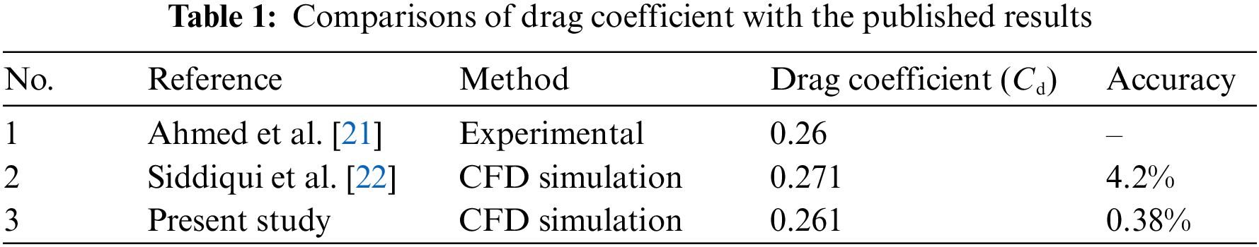

Figure 10: Comparison of velocity distribution between simulation and experiment
The Hypermesh software is utilized to generate a mixed mesh consisting of tetrahedral and pentahedral cells for the Ahmed body with the wheel. Two mesh refinements are applied near the wheel and car body surfaces using tetrahedral elements, while the pentahedral elements are generated further away in the domain using solid mapping. Following the same mesh structure used for the mesh validation case, three meshes, named Mesh 1, Mesh 2, and Mesh 3, are created, containing 15.02 million, 18.51 million, and 22.46 million cells, respectively. As indicated in Table 2, the drag coefficients decrease with an increasing number of grid cells. The Cd value error for Mesh 1, Mesh 2 and Mesh 3 is 0.002. It is worth noting that the calculation accuracy is positively correlated with the number of cells; however, excessive cell count can reduce computational efficiency. Therefore, Mesh 2 is selected for further research, as illustrated in Fig. 11.
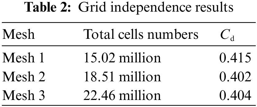

Figure 11: The mesh around the car body and the front wheel
3 Parameter Investigation and Optimization
3.1 Simulation of Isolated Wheel
While the wheel structure has a significant impact on the aerodynamic drag of the wheel, it is important to note that wheel aerodynamics are independent of the overall vehicle aerodynamics. In other words, reducing the aerodynamic drag of the wheel can have a positive effect on the vehicle drag. This perspective has been supported by previous research [10].
To define the computational domain, the dimensions of the isolated wheel, including length (LW = 150 mm), width (WW = 50 mm), and height (HW = 150 mm), are taken into consideration. The boundaries of the domain are designed to be 20 times the length of the wheel (20 LW) in length, 10 times the width of the wheel (10 WW) in width, and 5 times the height of the wheel (5 HW) in height, as depicted in Fig. 12. The wheel is positioned at the center of the width direction, with a clearance of 7 times the wheel length (7 LW) from the inlet. The resulting blockage ratio is approximately 2%. For mesh generation, the commercial software Hypermesh is employed to create the volume mesh and boundary layer cells. A cylindrical-shaped volumetric control is applied around the wheel, while a rectangular-shaped volumetric control is used in the wake region to accurately capture flow features in these areas. Prism layers, triangular elements, and tetrahedral elements are utilized for meshing. The prism layers, consisting of 5 inflation layers with a growth rate of 1.2, are employed to capture the boundary layer flow. The wheel rotation is simulated using the moving reference frame method. To test the grid sensitivity of the simulation, three different gird resolutions, named as the coarse, medium and fine, are proposed, and the response Cd is shown in Table 3. The fine grid distribution around the wheel are shown in Fig. 12b. Additionally, the fine grid ensured a y+ value of less than 2, as shown in Fig. 13.

Figure 12: Computational domain sizes and grids
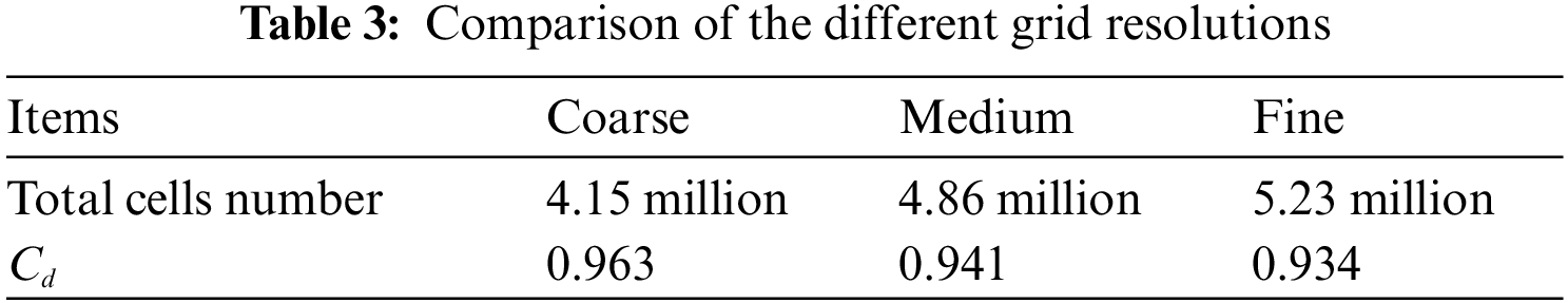

Figure 13: Y+ values distribution around wheel surface
3.2 Parameters Selection and DOE
The structure of the rim spoke plays a crucial role in aerodynamic drag as it affects the airflow. Considering the same rim area coverage of 50% and a fixed wheel diameter of 75 mm, five design parameters of the rim spoke are studied: the fillet angle α, inside arc radius R1, outside arc radius R2, and the arc tangent lines L1 and L2, as depicted in Fig. 14.

Figure 14: Schematic diagram of a single spoke
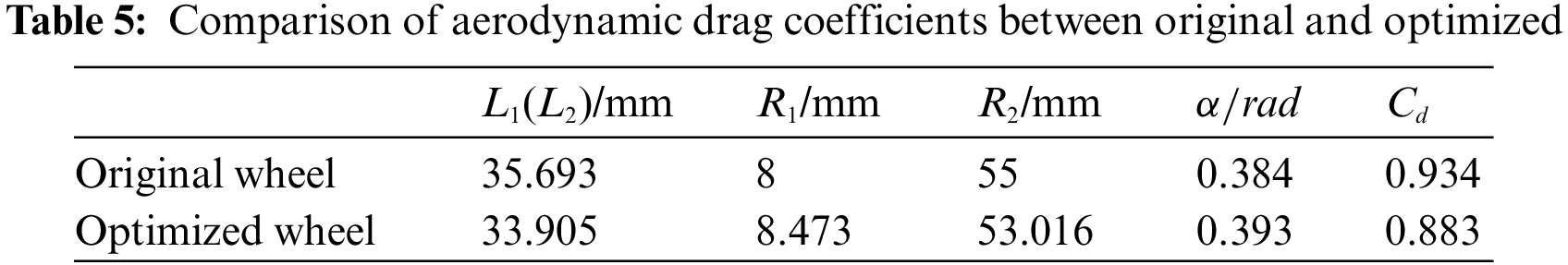
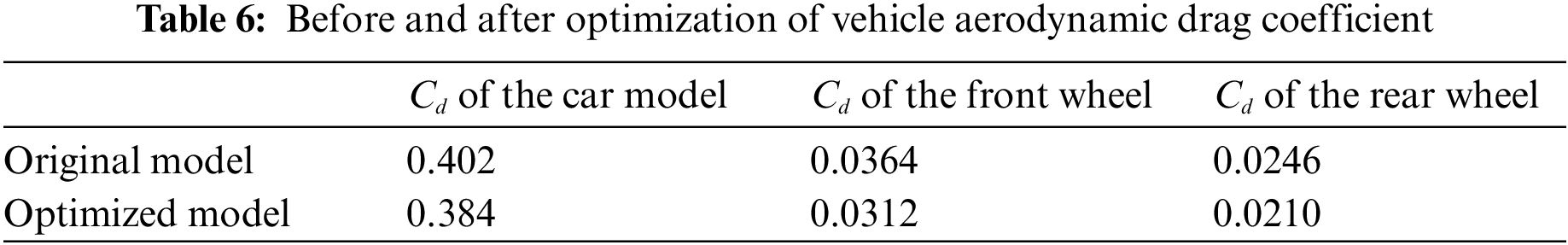
In the original spoke design, the fillet angle α is set at 0.384 rad, with inside arc radius R1 and outside arc radius R2 of 8 and 55 mm, respectively. The arc tangent lines L1 and L2 are both 35.693 mm. To examine the influence of different spoke design parameters on wheel aerodynamic drag while maintaining the same opening area of 5S, the parameter variables are assigned the following values:
The Optimal Latin Hypercube design method [24,25], known for optimizing the combination of factor levels, is employed to generate 20 sample points in this study. All 20 cases are simulated with an inlet velocity of 40 m/s. The factors and corresponding levels, as well as the obtained results, are summarized in Table 4. Fig. 15 showcases the designs of samples 7, 11, and 16. The impact of parameter variables on the wheel’s aerodynamic drag coefficient is depicted in Fig. 16. It is evident that the fillet angle α has the greatest influence on the drag coefficient, followed by the outside arc radius R1. Conversely, the arc tangent lines L1 and L2 exhibit minimal impact on the drag coefficient.
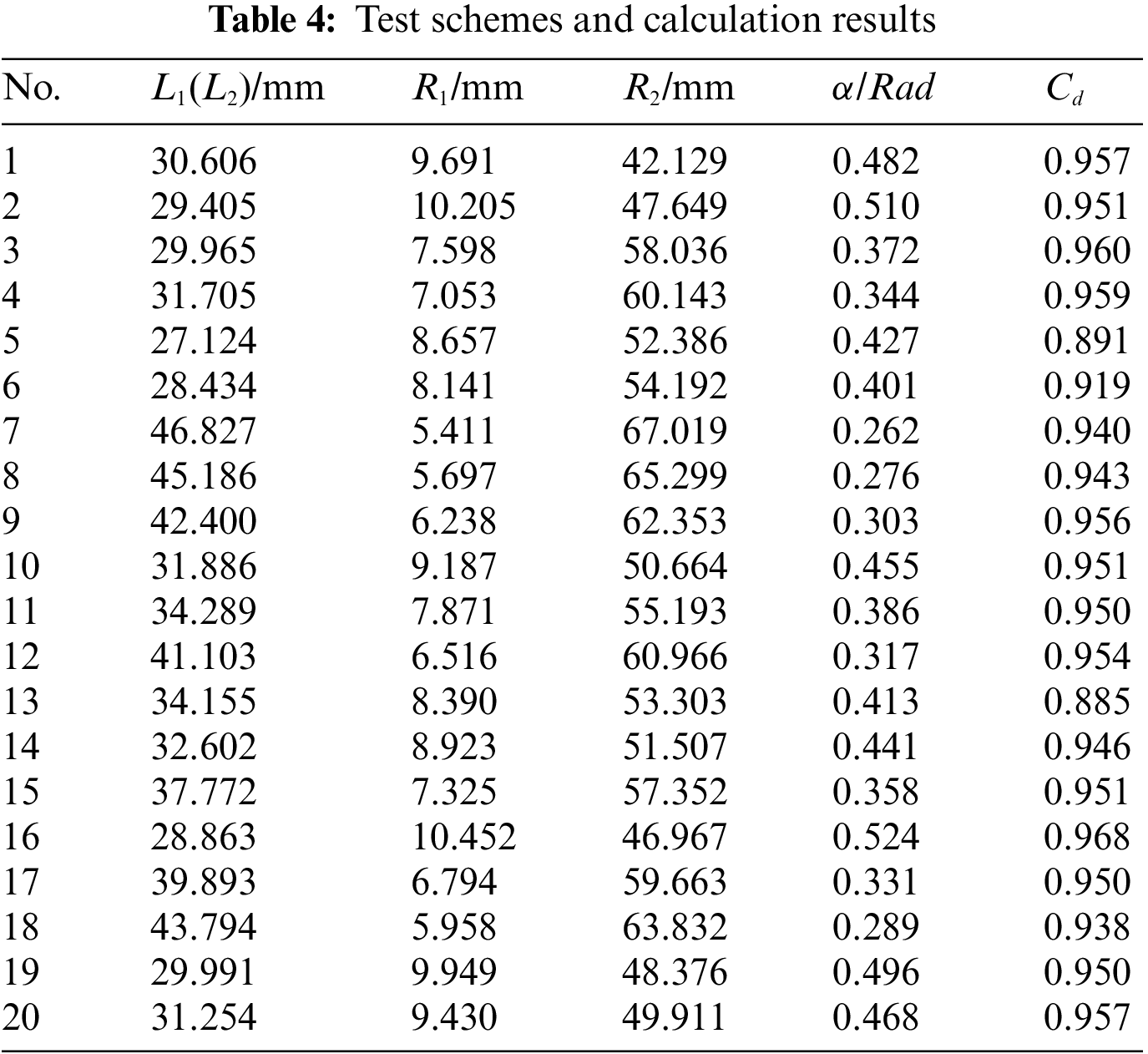

Figure 15: Geometric models of some typical Schemes

Figure 16: Contribution of different design variables for Cd
3.3 Surrogate Model and Parameters Optimization
The Kriging surrogate model, known for its effectiveness in curve interpolation and response surface approximation, is utilized in this study for the approximate evaluation of design schemes [26]. The correlation coefficient R2 is selected as a measure to evaluate the accuracy of the built Kriging surrogate model. Fig. 17 illustrates the forecast accuracy between the simulation results and predicted results, with an R2 value of approximately 0.98. This indicates that the established surrogate model possesses sufficient accuracy for optimizing the parameters of the wheel spoke.

Figure 17: Kriging surrogate model accuracy
The adaptive simulated annealing (ASA) algorithm is chosen to obtain the global optimal solution for the design parameters of the wheel spoke. In this algorithm, the objective function aimed to minimize the wheel drag coefficient, while the constraint conditions are defined as
4 Results Analysis and Discussion
To investigate the impact of the optimized wheel spoke on the flow field and aerodynamic drag, several vertical sections and a longitudinal section are analyzed to compare the flow field information before and after optimization, as depicted in Fig. 18. This analysis aims to reveal the differences resulting from the optimized wheel spoke design.

Figure 18: Four different sections
The pressure drag represents the primary component of the aerodynamic drag. Fig. 19 illustrates the pressure distribution in the Y = 0 section of the wheel. It is evident that the air pressure around the front of the wheel remains relatively unchanged, while the pressure at the rear undergoes noticeable changes, with increased pressure values. The observed increase in pressure magnitude indicates a decrease in pressure drag, resulting in a reduced overall wheel drag.

Figure 19: Pressure of longitudinal plane in wheel before and after optimization
Fig. 20 illustrates the streamlines and vorticity within the wheel cavity at different Z-direction sections. Due to the obstructive effect of the wheel, the airflow initially separates at the front edge of the wheel, forming two streams that propagate downstream. The presence of the wheel cavity introduces unsteady flow characteristics and generates numerous flow vortices in the low-velocity airflow. When the airflow impacts the rear edges of the wheel cavity, the airflow velocity around the inner edge decreases while vorticity increases. Under the driving effect of high-speed airflow from the front edge, the vorticity within the inside zone is greater than that in the outside zone. With improved ventilation capacity of the spoke, the vorticity distribution within the cavity of the optimized wheel is smaller compared to the original wheel. Fig. 20a demonstrates minimal changes in the flow field around the outside zone of the wheel, while significant differences are observed in the vicinity of the inside zone. The optimized rim design displaces the vortex core backward and reduces the vorticity in the central region. However, the vorticity intensity within the optimized wheel cavity is higher than that of the original wheel. Fig. 20b compares the flow field at the Z = 0 mm section. Although the flow field behind the wheel appears similar, the optimized wheel features a wider opening that more effectively directs the airflow into the wheel cavity, resulting in a larger region of streamline vortices near the inner edge of the rim. Fig. 20c reveals the presence of vortex pairs behind the optimized wheel, which are absent in the original wheel. The vortices within the optimized wheel cavity exhibit relatively uniform magnitudes, indicating a more stable airflow and reduced flow energy losses. Moreover, the regions of higher vorticity in the optimized wheel are smaller compared to those in the original wheel.

Figure 20: Comparison of vorticity distribution in different sections
4.2 Aerodynamic Characteristics of Ahmed Body with Wheel
Fig. 21 illustrates the comparison of the time-average pressure coefficient distributions on the body surfaces. It can be observed that compared to the original wheel, the pressure coefficient around the front wheel increases while it decreases around the rear wheel. This indicates that the rim spoke structure has a direct influence on the airflow movement around the wheel. As for the back surface of the car body, the pressure coefficient reduces on the slant rear surface, but due to changes in airflow conditions in the under-body gap, there is a significant increase in the pressure coefficient on the vertical rear surface. The drag coefficients are presented in Table 6. It can be seen that the drag coefficient of the Ahmed body is reduced by 4.7%, while the front and rear wheels experience a reduction of 16.7% and 17.1% in drag coefficient, respectively. From these findings, it can be concluded that improving the geometric characteristics of the wheel’s aerodynamic shape is an effective measure to enhance automotive aerodynamic performance and reduce drag.

Figure 21: Comparison of surface pressure coefficients around different Ahmed body
The iso-surface of zero total pressure coefficient is selected to characterize the location, strength, and size of flow separation, and the difference in the distribution of zero total pressure coefficient is used to clarify the reasons for pressure drag [27]. Fig. 22 displays the iso-surface of zero total pressure coefficient for the original wheel and optimized wheel. It is evident that the size of the zero total pressure coefficient region is larger for the original front and rear wheels compared to the optimized wheel. This indicates that the structural changes in the wheel spoke have a direct influence on the airflow movements around the wheel, which also extends to the wake flow. Drag reduction relies on pressure recovery around the car body. As depicted in Fig. 22, the separation bubbles around the front wheel are larger than those around the rear wheel in both the original and optimized configurations. This implies that the pressure recovery in the front wheel is slower, resulting in higher aerodynamic drag compared to the rear wheel [5,28]. In comparison, the optimized wheel exhibits suppressed flow separation and reduced separation bubble size based on the differences in the iso-surface of zero total pressure coefficient. This delay in flow separation leads to a decrease in velocity fluctuations and turbulent kinetic energy. Consequently, the aerodynamic performance of the Ahmed body with the optimized wheel is improved.

Figure 22: Iso-surface of zero total pressure coefficient for car body with different wheel model
The Q-criterion is based on the second invariant of the velocity gradient denoted as Q, which also includes the condition that the ambient pressure should be higher than the pressure of the vortex to separate it. The identification of vortex structures using the Q-criterion has been applied in vehicle aerodynamics [29]. Fig. 23 illustrates the Q-criterion for the original and optimized wheel. In the case of the front wheel, the large-scale vortical structure encompassing the five spoke appears similar in both the original and optimized configurations. Additionally, there is a distinct horseshoe vortex structure observed around the leeward side of the front wheel. However, in the optimized wheel, the vortex development on the leeward side is reduced compared to the original wheel, indicating lower fluctuations in the turbulent flow.

Figure 23: Vortex structure of front wheels before and after optimization (Q = 40000)
For the rear wheel, the original wheel model exhibits a prominent vortex structure on the windward side, extending towards the spoke as depicted in Fig. 24. However, this large vortex is absent in the optimized wheel, indicating effective control of flow separation on the windward side. In the optimized wheel, the development of vortices on the leeward side of the rear wheel is reduced compared to the original wheel. Additionally, the longitudinal vortex development is shorter and exhibits lower strength and intensity compared to the original wheel. These differences in vortex structures imply that the available kinetic energy for the eddies is reduced at an earlier stage.

Figure 24: Vortex structure of rear wheel before and after optimization (Q = 40000)
The boundary layer distribution on four planes, defined by the range of velocities less than 0.99u, is depicted in Fig. 25a. Fig. 25b presents a comparison of the boundary layer between the original wheel and the optimized wheel. The values in the figure represent the normalized airflow velocity using U/Uin, where Uin corresponds to the inlet velocity of 40 m/s. From Fig. 25b, it can be observed that the boundary layer thickness around the wheel gradually increases along the car body, while the velocity gradient decreases. However, there are differences in the boundary layer thickness around the top of the car body. In plane P2, the boundary layer thickness is smaller for the original wheel, resulting in higher viscous drag on the original car body. Conversely, in plane P4, the boundary layer thickness is smaller for the optimized wheel, leading to higher viscous drag on the optimized car body. These differences in the boundary layer affect the velocity field and result in variations in the iso-surface of zero total pressure coefficient (Fig. 8). Therefore, it can be inferred that the pressure drag plays a dominant role in the overall aerodynamic performance compared to the viscous drag.
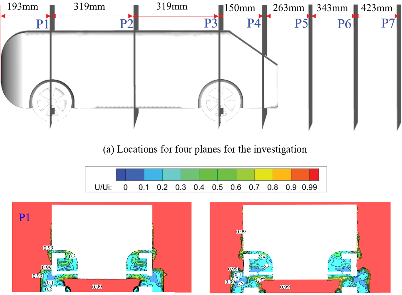

Figure 25: Locations and boundary layer distribution for the different four plane
The turbulent kinetic energy (TKE) is a crucial parameter that serves to connect the mechanisms of drag reduction. It represents the mean kinetic energy available per unit mass of turbulent eddies. Fig. 26 illustrates the variation in TKE for the original and optimized wheel. The TKE is predominantly concentrated on the upper slant surface. As the distance increases in the wake region, the TKE decreases. However, when compared to the original wheel, the TKE in the surrounding flow area exhibits a significant decrease. This indicates that the size of the low-vortex region is larger, and the dissipation of flow energy can be effectively controlled. Typically, lower TKE signifies more stable velocity pulsations, which may result in larger vortices and lower base pressure. This observation aligns with the findings from the pressure coefficient results presented in Fig. 21.


Figure 26: Turbulent kinetic energy at different planes in the original and optimized wheel
This study aimed to numerically investigate the influence of wheel spoke design on the aerodynamics of an isolated wheel and the Ahmed model. The main conclusions are as follows:
(1) The aerodynamic characteristics of an isolated wheel are studied through numerical simulation, focusing on four design parameters of wheel spoke: the fillet angle α, inside arc radius R1, outside radius R2, and chord length L1. The drag coefficient is selected as the objective. Using the Optimal Latin Hypercube (OLH) design, 20 sample points are generated, and their corresponding drag coefficients are calculated. Sensitivity analysis revealed that the angle α had the greatest impact on the drag coefficient, followed by the outside arc radius R1, while the arc tangent lines L1 and L2 had minimal influence.
(2) By utilizing the integrated approach of the Kriging surrogate model and adaptive simulated annealing algorithm, the optimal design parameters of the wheel spoke are obtained. Comparative analysis of the flow fields between the original and optimized wheels demonstrated that the optimized wheel influenced the airflow state inside the wheel cavity, reducing flow instability around the wheel. As a result, the optimized wheel achieved a drag reduction of 5.7%.
(3) The aerodynamic drag of an Ahmed body equipped with the original and optimized wheel is investigated, revealing a decrease of 4.7% in the drag coefficient for the Ahmed body with the optimized wheel. Analysis of flow features indicated that the drag reduction primarily relied on changes in the flow state around the wheel to suppress separation bubbles, as well as the influence on boundary layer thickness around the car body and reduction of turbulent kinetic energy in the wake flow. Further investigations can focus on developing new active or passive devices, for example the active drag reduction of bionic non-smooth surface and the passive drag reduction of vortex generator, to further reduce drag and enhance aerodynamic performance of the wheel and the vehicle.
Acknowledgement: The authors are grateful for the support by the National Natural Science Foundation of China, and Postdoctoral Foundation of China.
Funding Statement: The authors are pleased to acknowledge funding of the National Natural Science Foundation of China (Nos. 52072156, 51605198), and Postdoctoral Foundation of China (2020M682269).
Author Contributions: The authors confirm contribution to the paper as follows: study conception and design: Huihui Zhai; data collection: Dongqi Jiao; analysis and interpretation of results: Haichao Zhou; draft manuscript preparation: Huihui Zhai. All authors reviewed the results and approved the final version of the manuscript.
Availability of Data and Materials: The data undering this article will be shared on reasonable request to the corresponding author.
Conflicts of Interest: The authors declare that they have no conflicts of interest to report regarding the present study.
References
1. Huminic, A., Huminic, G. (2017). Aerodynamic study of a generic car model with wheels and underbody diffuser. International Journal of Automotive Technology, 18, 397–404. [Google Scholar]
2. Altaf, A., Omar, A. A., Asrar, W. (2014). Passive drag reduction of square back road vehicles. Journal of Wind Engineering and Industrial Aerodynamics, 134, 30–43. [Google Scholar]
3. Yang, X., Hu, Y., Gong, Z., Jian, J., Liu, Z. (2021). Numerical study of combined drag reduction bases on vortex generators and riblets for the ahmed body using IDDES methodology. Journal of Applied Fluid Mechanics, 15(1), 193–207. [Google Scholar]
4. Kim, D., Lee, H., Yi, W., Choi, H. (2016). A bio-inspired device for drag reduction on a three-dimensional model vehicle. Bioinspiration & Biomimetics, 11(2), 026004. [Google Scholar]
5. Yu, X., Jia, Q., Yang, Z. (2022). Comprehensive study of the aerodynamic influence of ground and wheel states on the notchback DrivAer. JEnergies, 15(3), 1–33. [Google Scholar]
6. Zhou, H., Jiang, Z., Wang, G., Zhang, S. (2021). Aerodynamic characteristics of isolated loaded tires with different tread patterns: Experiment and simulation. Chinese Journal of Mechanical Engineering, 34, 1–16. [Google Scholar]
7. Josefsson, E., Hobeika, T., Sebben, S. (2022). Evaluation of wind tunnel interference on numerical prediction of wheel aerodynamics. Journal of Wind Engineering and Industrial Aerodynamics, 224, 104945. [Google Scholar]
8. Jiang, F., Niu, J., Li, R., Wang, Y., Zhang, Y. (2023). Computational fluid dynamics analysis of effect of braking plate configurations on the aerodynamic behaviors of an ahmed car. Flow, Turbulence and Combustion, 110(2), 301–323. [Google Scholar]
9. Fackrell, J. E. (1974). The aerodynamic of an isolated tire rotating in contact with ground (Ph.D. Thesis). University of London, London. [Google Scholar]
10. Brandt, A., Berg, H., Bolzon, M., Josefsson, L. (2019). The effects of wheel design on the aerodynamic drag of passenger vehicles. SAE International Journal of Advances and Current Practices in Mobility, 1(3), 1279–1299. [Google Scholar]
11. Fang, J., Wang, F. L. (2019). A study on CFD simulation and wind tunnel test on aerodynamic effects of wheel rotation and drag reduction optimization. Automotive Engineering, 41(9), 1006–1012. [Google Scholar]
12. Fu, L., Hu, X., Zhang, S. (2006). Numerical simulation of influence of holes in wheel spokes on automotive external flow-field. Nongye Jixie Xuebao (Transactions of the Chinese Society of Agricultural Machinery), 37(1), 8–11 (In Chinese). [Google Scholar]
13. Elofsson, P., Bannister, M. (2002). Drag reduction mechanisms due to moving ground and wheel rotation in passenger cars. SAE Technical Paper, 2002-01-0531. [Google Scholar]
14. Saddington, A. J., Knowles, R. D., Knowles, K. (2007). Laser Doppler anemometry measurements in the near-wake of an isolated formula one wheel. Experiments in Fluids, 42(5), 671–681. [Google Scholar]
15. Croner, E., Bézard, H., Sicot, C., Mothay, G. (2013). Aerodynamic characterization of the wake of an isolated rolling wheel. International Journal of Heat and Fluid Flow, 43, 233–243. [Google Scholar]
16. Qiu, Z. (2009). Wheel aerodynamic developments by module-based prototype rims and stationary rim shields (Ph.D. Thesis). Chalmers University of Technology, Gothenburg. [Google Scholar]
17. Strachan, R. K., Knowles, K., Lawson, N. J. (2007). The vortex structure behind an ahmed reference model in the presence of a moving ground plane. Experiments in Fluids, 42(5), 659–669. [Google Scholar]
18. Corallo, M., Sheridan, J., Thompson, M. C. (2015). Effect of aspect ratio on the near-wake flow structure of an ahmed body. Journal of Wind Engineering and Industrial Aerodynamics, 147, 95–103. [Google Scholar]
19. Diasinos, S., Barber, T. J., Doig, G. (2015). The effects of simplifications on isolated wheel aerodynamics. Journal of Wind Engineering and Industrial Aerodynamics, 146, 90–101. [Google Scholar]
20. Liang, H., Sun, Y., Li, T., Zhang, J. (2022). Influence of marshalling length on aerodynamic characteristics of urban EMUs under crosswind. Journal of Applied Fluid Mechanics, 16(1), 9–20. [Google Scholar]
21. Ahmed, S. (1984). Some salient features of the time-averaged ground vehicle wake. SAE Paper, 840300. [Google Scholar]
22. Siddiqui, N. A., Chaab, M. A. (2020). A simple passive device for the drag reduction of an ahmed body. Journal of Applied Fluid Mechanics, 14(1), 147–164. [Google Scholar]
23. Meile, W., Brenn, G., Reppenhagen, A., Lechner, B., Fuchs, A. (2011). Experiments and numerical simulations on the aerodynamics of the ahmed body. CFD Letters, 3(1), 32–39. [Google Scholar]
24. Montazeri, F., Tavakoli, M. R., Salimpour, M. R. (2023). Improving thermal performance of rectangular microchannel heat sinks using porous layer: CFD simulation and optimization. Journal of Applied Fluid Mechanics, 16(8), 1574–1586. [Google Scholar]
25. Park, J. S. (1994). Optimal latin-hypercube designs for computer experiments. Journal of Statistical Planning and Inference, 39(1), 95–111. [Google Scholar]
26. Zhang, L., Zhou, H., Wang, G., Li, H., Wang, Q. (2022). Investigation of effects of tire contour on aerodynamic characteristics and its optimization. Proceedings of the Institution of Mechanical Engineers, Part D: Journal of Automobile Engineering, 236(12), 2756–2772. [Google Scholar]
27. McArthur, D., Burton, D., Thompson, M., Sheridan, J. (2018). An experimental characterisation of the wake of a detailed heavy vehicle in cross-wind. Journal of Wind Engineering and Industrial Aerodynamics, 175, 364–375. [Google Scholar]
28. Wang, Y., Sicot, C., Boree, J., Grandemange, M. (2020). Experimental study of wheel-vehicle aerodynamic interactions. Journal of Wind Engineering and Industrial Aerodynamics, 198, 104062. [Google Scholar]
29. Zhou, H., Chen, Q., Qin, R., Zhang, L., Li, H. (2021). Investigation of wheelhouse shapes on the aerodynamic characteristics of a generic car model. Advances in Mechanical Engineering, 13(12), 16878140211066842. [Google Scholar]
Cite This Article
 Copyright © 2024 The Author(s). Published by Tech Science Press.
This work is licensed under a Creative Commons Attribution 4.0 International License , which permits unrestricted use, distribution, and reproduction in any medium, provided the original work is properly cited.
 Downloads
 Citation Tools