
 Submit a Paper
 Propose a Special lssue
 Open Access
ARTICLE

Investigations on High-Speed Flash Boiling Atomization of Fuel Based on Numerical Simulations
1 School of Aerospace Engineering and Applied Mechanics, Tongji University, Shanghai, 200092, China
2 Beijing Mechanical Equipment Research Institute, Beijing, 100854, China
* Corresponding Author: Lihua Wang. Email:
(This article belongs to the Special Issue: Advanced Computational Methods in Fluid Mechanics and Heat Transfer)
Computer Modeling in Engineering & Sciences 2024, 139(2), 1427-1453. https://doi.org/10.32604/cmes.2023.031271
Received 31 May 2023; Accepted 17 November 2023; Issue published 29 January 2024
 View Full Text
 Download PDF
Abstract
Flash boiling atomization (FBA) is a promising approach for enhancing spray atomization, which can generate a fine and more evenly distributed spray by increasing the fuel injection temperature or reducing the ambient pressure. However, when the outlet speed of the nozzle exceeds 400 m/s, investigating high-speed flash boiling atomization (HFBA) becomes quite challenging. This difficulty arises from the involvement of many complex physical processes and the requirement for a very fine mesh in numerical simulations. In this study, an HFBA model for gasoline direct injection (GDI) is established. This model incorporates primary and secondary atomization, as well as vaporization and boiling models, to describe the development process of the flash boiling spray. Compared to low-speed FBA, these physical processes significantly impact HFBA. In this model, the Eulerian description is utilized for modeling the gas, and the Lagrangian description is applied to model the droplets, which effectively captures the movement of the droplets and avoids excessive mesh in the Eulerian coordinates. Under various conditions, numerical solutions of the Sauter mean diameter (SMD) for GDI show good agreement with experimental data, validating the proposed model’s performance. Simulations based on this HFBA model investigate the influences of fuel injection temperature and ambient pressure on the atomization process. Numerical analyses of the velocity field, temperature field, vapor mass fraction distribution, particle size distribution, and spray penetration length under different superheat degrees reveal that high injection temperature or low ambient pressure significantly affects the formation of small and dispersed droplet distribution. This effect is conducive to the refinement of spray particles and enhances atomization.Keywords
Over the last few decades, significant efforts have been made to increase the efficiency of internal combustion engines and simultaneously reduce tailpipe emissions. The spray atomization process in internal combustion engines directly affects the engine’s thermal efficiency and emissions [1]. In gasoline direct injection (GDI) engines, rapidly forming uniform and finely atomized particles is essential, which demands a spray with proper penetration length, dispersed droplet distribution, and small droplets [2]. Although increasing the injection pressure can meet these requirements [3], it leads to a significant shortcoming known as wall-wetting caused by its longer penetration [4,5]. On the other hand, flash boiling atomization (FBA) is a promising approach for improving the atomization process. Flashing of hot liquid resembles a boiling process characterized by thermal non-equilibrium (temperature difference across the interface). When the liquid’s temperature is higher than its boiling point, or the local pressure is lower than its saturation pressure, the vapor bubble explosion formed in the superheated liquid can promote the atomization process, thus significantly improving the atomization performance. As the viscosity, surface tension, and latent heat of vaporization of the fuel droplets all decrease with the increase in temperature [6–9], flash boiling causes a rapid phase transition from liquid to vapor. This phase transition leads to volume expansion and changes in spray angle, spray width, droplet size, and penetration, enabling flash boiling to produce finer droplets and even particle distribution.
Many researchers have studied FBA from theoretical, experimental, and numerical aspects. The theoretical studies have investigated the flash boiling process’s theories, including flashing inception, nucleation, bubble growth [10,11], evaporation wave [12,13], and spray collapse [14,15]. These works explored the physics and modeling of flashing flows, investigated evaporation waves in liquid jet flashing regimes, and examined spray collapse mechanisms under varied conditions. Despite these efforts, understanding physical processes, such as bubble formation in superheated liquid, remains insufficient. In experimental examinations, numerous studies have focused on the effects of superheating degree and injector configuration on flash boiling spray characteristics, visualizing the atomization process to study motion and features. The most commonly used experimental methods include phase Doppler anemometry (PDA) [16], phase Doppler particle analyzer (PDPA) [17], schlieren [18], Mie scattering [19], laser-induced exciplex fluorescence (LIEF) [20,21]. These investigations shed light on flash-boiling spray collapse mechanisms, plume-to-plume interactions, and distinctive characteristics of flash-boiling sprays compared to traditional liquid sprays. The findings contribute valuable insights for optimizing fuel atomization and combustion processes in direct-injection engines. However, experiments were hindered by the high cost of equipment and materials. Limited samples made predicting flash boiling phenomena under unknown conditions challenging, and preparing for experiments required significant time investment.
Since the theory of FBA is quite complicated, covering many physical processes, and experiments under high temperature and high pressure are hard to control, more investigations have been achieved through numerical simulations [22,23]. These works collectively explored various aspects of flash boiling phenomena in fuel sprays, focusing on gasoline direct injection (GDI) injectors. They covered theoretical, experimental, and numerical studies, analyzing factors such as superheating degree and injector configuration [24,10]. The collapse mechanisms of flash boiling sprays were investigated through multiple perspectives, including the velocity field, temperature field, vapor concentration field, and droplet diameter. Additionally, the review highlighted the importance of understanding flash boiling spray behaviors for applications like injector design and injection strategies. Another study addressed the modeling challenges of flash boiling effects in sprays, emphasizing the need for an economical and computationally efficient methodology. In these studies, the Eulerian-Eulerian and Eulerian-Lagrangian methods are typical for simulating fuel spray. In Eulerian-Eulerian methods [25,26], the gas and liquid phases are calculated based on the Eulerian description, where the internal flow and near-field spray can be obtained directly. The studied problem domain includes the nozzle and spray field to predict the flash boiling process considering nucleation, bubble growth, and evaporation [27,28]. Numerous interface tracking methods can be utilized to capture the spray, such as the volume of fluid (VOF) [29,30], piecewise-linear interface calculation (PLIC) method [31], level-set method, and VOF level-set (VOF-LS) [32] methods, and others. However, these methods require very dense meshes to clearly trace the gas-liquid interfaces, making them computationally expensive. In recent years, a method based on the Euler framework has also experienced rapid development, providing the capability to combine the Euler and Lagrangian methods using a transition mechanism [33–35]. The initial jet and primary breakup are predicted using the Euler method on a sufficiently fine mesh; if a liquid block satisfies the transformation conditions, it will be converted into Lagrangian particles, simplifying calculations. However, this method still involves significant computational complexity and is prone to divergence. Moreover, most liquid is atomized into droplets at the outlet in the flash atomization process, with almost no continuous liquid phase present. Therefore, this method is not suitable for the current simulation work.
In order to save computational costs, more simulations of flash boiling spray resort to Eulerian-Lagrangian methods. Models based on Eulerian-Lagrangian descriptions include primary atomization models [36,37], secondary atomization models [35], evaporation [38,39] and boil models [40,41], and heat and mass transfer models [42,43], exploring phenomena like flash-boiling, droplet dynamics, spray structure, and the intricate interplay between liquid and gas phases [44,45]. The methodologies included numerical simulations, machine-learning algorithms, parametric studies, and novel models. An et al. [46], Price et al. [40], and Zhou et al. [39] investigated the influence of the evaporation model on numerical results and conducted qualitative studies on the results, providing a reference for subsequent simulation work from an academic perspective. Liao and Lucas [10] reviewed the models for flashing inception, nucleation, bubble growth, vapor generation, and interfacial area density. They noted that the models for representing the formation, growth, and breakage of bubbles in superheated liquid are still far from the requirements of engineering applications. For instance, many models are only applicable under ideal conditions or are more or less empirical, resulting in low accuracy of numerical simulations. For instance, the Homogeneous Relaxation Model (HRM) treats the transition of the thermodynamic system from non-equilibrium to equilibrium as a relaxation process. The two states are bridged by an empirical coefficient, i.e., the relaxation time [10].
When the outlet speed of the nozzle exceeds 400 m/s, the high-speed FBA requires a very dense mesh to trace the flow field information of the gas and droplets and the gas-liquid interfaces. Millions or even billions of grids should be introduced, and the data post-processing becomes quite burdensome [25,47]. Due to the violent liquid flashing, a high-speed gas-liquid mixture is formed near the exit of the nozzle. Moreover, the physical mechanism of high-speed flash boiling is very complicated. The existing models often suffer from low simulation accuracy for high-speed FBA. Generally, the errors may exceed 15% [37]. Besides, ambient pressure and temperature are believed to play important roles in atomizing superheated liquids. Nevertheless, most studies only consider one of these factors [10].
This study establishes a high-speed flash boiling atomization (HFBA) model for fuel atomization, catering to scenarios where the outlet speed exceeds 400 m/s, reaching up to approximately 700 m/s. This model encompasses the processes of primary atomization, secondary atomization, and the interaction between gas and liquid during atomization. The Eulerian method is employed for modeling the gas, while the Lagrangian method is utilized for simulating the liquid. These methods enable effective capture of the droplets and gas-liquid interfaces. Implementing an adaptive mesh enhances the resolution of the gas-liquid interfaces, improving the model’s accuracy. The model operates with fewer than one hundred thousand grids, maintaining a solution error below 10% compared to experimental data [48]. Subsequently, this validated model is applied to examine the effects of fuel injection temperature and ambient pressure on various aspects, such as the velocity field, temperature field, vapor mass fraction distribution, particle size distribution, and spray penetration length. This comprehensive application delineates the entire process and intricacies of the HFBA.
Considering the computational costs, the Eulerian-Lagrangian method is adopted for fuel atomization simulations. Compared to the Eulerian-Eulerian method, this method simplifies capturing the flow field, particle size, and other information post-atomization and facilitates the design and optimization of the numerical model [36,37]. The spray mixing of liquid fuel in a combustion chamber is a transient, complex, multiphase flow process. This process involves the formation of droplets, fragmentation, collision, aggregation, boiling, evaporation, vaporization, and the mutual coupling with air, integrating and superimposing many processes [41].
2.1 Eulerian Description for the Gas
The flash boiling spray of fuel is a complex gas-liquid two-phase flow process, encompassing turbulent flow, gas-liquid heat transfer, and mass transfer processes. These physical processes adhere to basic conservation laws, including mass and momentum conservation. For the heat transfer problem, the law of energy conservation and the equation of state of the ideal gas are also applicable [49,50].
(1) Mass conservation equation
In this study, the three-dimensional problem is simplified to be a 2D axisymmetric problem, where
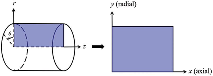
Figure 1: Coordinate conversion
where
(2) Momentum conservation equations
For the 2D axisymmetric problem, the momentum conservation equation is given by
where
(3) Energy conservation equation
The energy conservation equation can be expressed as
where
(4) Vapor-liquid equilibrium equation
The vapor-liquid equilibrium equation is described as follows:
where
(5) Equation of state of the ideal gas
For the ideal gas, the equation of state can be expressed by
where
2.2 Lagrangian Description for the Droplets
This study simulates the FBA and evaporation processes of fuel using the discrete phase model (DPM) in the Lagrangian coordinate system. The DPM model captures various physical processes in the FBA process, including liquid spraying into the combustion chamber, droplet formation, and the exchange of momentum, mass, energy, and species transfer between droplets and gas [36,38,41].
The droplet is considered a discrete particle, and the particle trajectory can be predicted by solving the equation of motion under the Lagrangian reference system. The equation of motion is given as follows [51]:
where
where
2.2.2 Heat and Mass Transfer Model
(1) Droplet heating and cooling
When the temperature of the droplet is below the defined evaporation temperature
where
where
(2) Evaporation of droplets
The evaporation law can be utilized to evaluate the evaporation of a droplet in the discrete phase when the temperature of the droplet satisfies the following conditions
where
where
During the evaporation of the droplet, the reduction of the mass of the droplet is according to the following equation:
where
When
where
(3) Boiling of droplets
When the boiling condition
where
2.3 Coupling between Gas and Droplets
In the interactions between gas and droplets, exchanges of mass and momentum occur, as illustrated in Fig. 2. Regarding mass exchange, evaporation constantly occurs on droplet surfaces, with vapor entering the gas field as a source term for the continuous gas phase. In terms of momentum exchange, the droplet’s motion trajectory is influenced by the continuous gas field, and the droplet motion also impacts the continuous gas field flow. The equations for mass and momentum exchanges are detailed as follows.
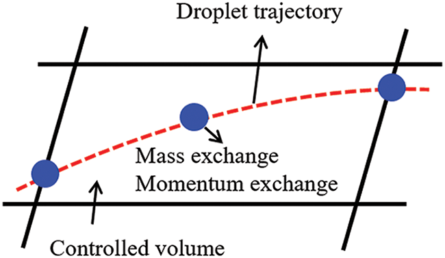
Figure 2: The mass and momentum exchange between the dispersed droplet and the continuous gas
(1) Momentum exchange
The transfer of momentum from the gas to the droplets can be calculated by examining the change in momentum of the droplets when they pass through each control volume. The change in momentum can be described as follows [55]:
where
(2) Mass exchange
The mass transfer from the droplets to the gas can be evaluated by computing the change in mass of the droplets when they pass through each control volume. The mass change
where
Turbulence is a nonlinear and complex flow that induces turbulent fluctuations, resulting in mass and momentum exchange and concentration changes between fluid media. Common numerical methods for modeling turbulence include the direct simulation method (DNS), large eddy simulation (LES), and Reynolds-averaged Navier-Stokes (RANS) method. DNS directly solves the Navier-Stokes equation without a turbulence model, encompassing the flow field from the turbulent dissipation scale (Kolmogorov scale) to the large eddy scale, requiring a very small time step and refined grid scale [56,57]. LES solves the equation directly for large eddies, using models for small-scale eddies [58]. Although DNS and LES can achieve accurate simulations, their computational processes are complex and costly. Hence, they are typically used for simple and ideal flow fields. The unsteady Reynolds-averaged Navier-Stokes method (URANS) decomposes flow parameters into time-averaged and pulsation quantities, then reintegrates these values into the Navier-Stokes equation solution, offering cost-effectiveness and good accuracy [59,60]. This study selects the k-epsilon turbulence model in URANS to solve two transport equations for turbulence determination [61]. This model effectively simulates the diffusion process in jet phenomena and handles locations with large flow field parameter gradients [60]. The transport equations of the k-epsilon model are presented as follows:
where
2.5 Initial Conditions Based on the Primary Atomization Model
In the HFBA process, the fuel undergoes intense heat and momentum exchange with surrounding air during the primary atomization period. As a critical component of the atomization process, the accuracy of the entire simulation depends on the model selection for this period [36,62,43]. This work chooses the effervescent atomizer model for primary atomization, accurately presenting information on velocity, temperature, droplet size distribution, and the flow field around the nozzle post-initial atomization.
Effervescent atomization is a process where a jet of superheated liquid is injected, and upon leaving the nozzle, the volatile liquid rapidly boils and undergoes phase change. This sudden phase change effectively breaks the continuous liquid stream into small droplets with a wide atomization angle, forming a droplet group. In the model, the initial droplet velocity is calculated using the law of conservation of mass. It is assumed that the nozzle exit’s cross-sectional area is
where
The maximum droplet diameter is set to be the effective diameter of the nozzle
where
where
and
where
Post-primary atomization, large droplets may further fragment in subsequent motions. The WAVE model, which is applicable to high Weber number problems, is introduced in this paper to simulate the HFBA process of fuel [63–65]. The WAVE model posits that droplet breakup time and the size distribution of broken droplets relate to the fast-growing Kelvin-Helmholtz instability wave. The dispersion equation is presented as follows [26]:
where
The most unstable growth rate
where
The radius of the newly-formed droplets is proportional to the wavelength of the fastest-growing unstable surface wave on the parent droplet
where
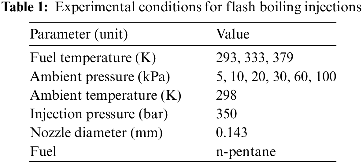
In this section, several examples of numerical simulations for the HFBA process are presented. The experimental data from Li et al.’s study [48] serves as the reference solution. In these experiments, a single-component fuel, n-pentane, is used for the HFBA tests. The fuel line is heated around the fuel rail using a high-pressure nozzle from a gasoline direct injection (GDI) engine, achieving fuel flash boiling in the test chamber by heating the fuel jet. The experimental conditions are listed in Table 1.
3.1 Mesh Independent Analysis and Model Validation
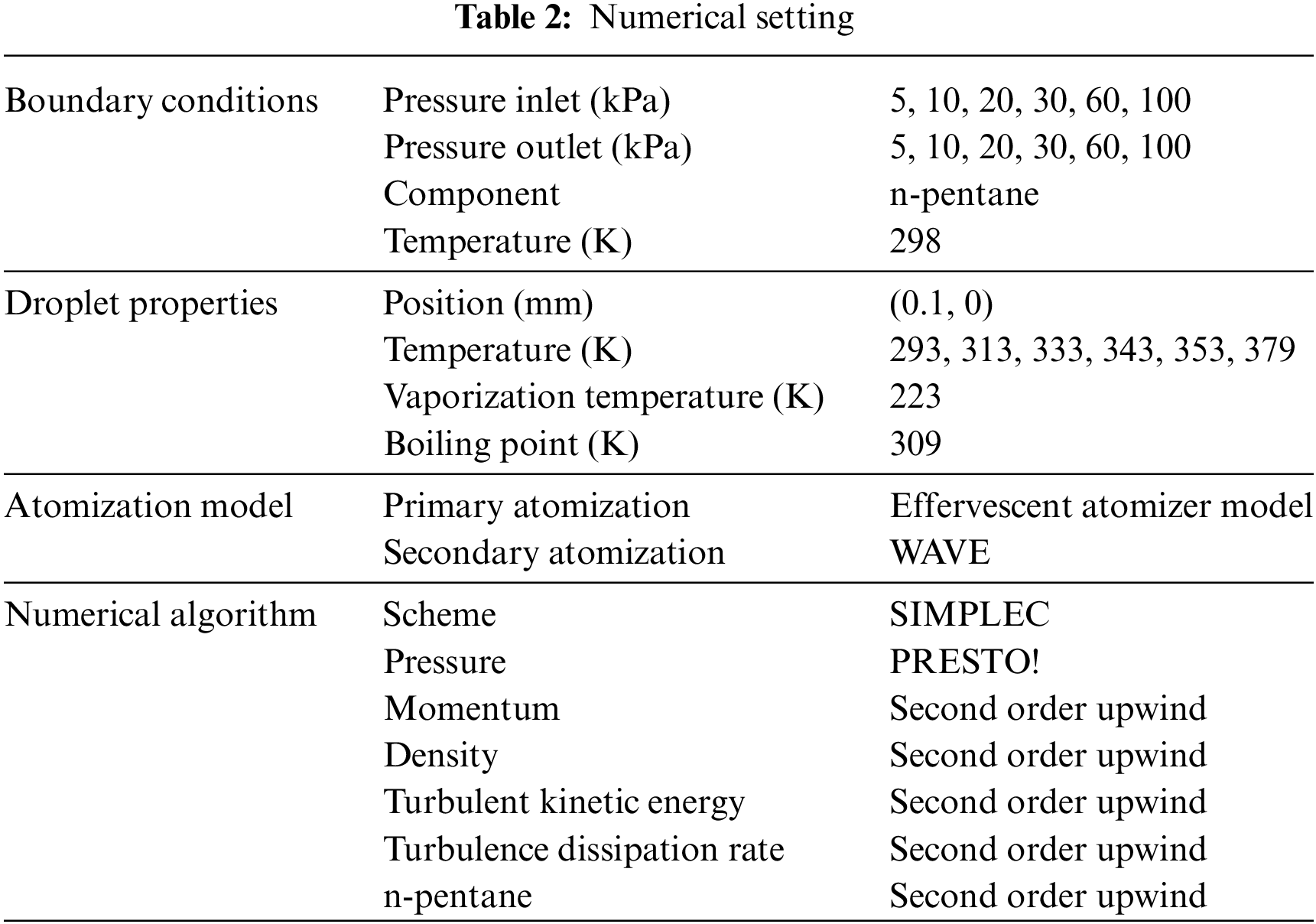
In the numerical simulations, a 2D axisymmetric geometry problem is studied, as depicted in Fig. 3. The problem domain extends 70 mm in length and 50 mm in width. The standard wall function [50,64] is applied to the boundary, which is positioned far from the nozzle and minimally affects the flash spray process. The detailed numerical settings for the simulations are listed in Table 2. Superheated fuel is injected from the fuel inlet into a test chamber filled with nitrogen at room temperature. Under varying ambient pressures and injection temperatures, the fuel undergoes changes like boiling, fragmentation, droplet collision, and evaporation, causing it to break into smaller droplets, ejected from the spray field outlet.
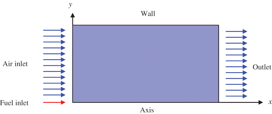
Figure 3: Coordinate conversion
For the finite volume method, the accuracy of simulation results depends on mesh distribution. Near the nozzle, where a large number of liquids boil and vaporize instantaneously, forming an extremely high-velocity jet stream with drastic changes in temperature, momentum, and species concentration, mesh refinement is crucial. As shown in Fig. 4, locally encrypted mesh with a growth rate of about 1.05 is employed for this example, covering an area approximately 15 mm long and 10 mm wide. The solutions converge under this mesh refinement, as demonstrated in Fig. 5, where the injection temperature is 333 K and the ambient pressure is 20 kPa. When the number of elements exceeds 70200, the solutions become convergent, and beyond this point, they are almost mesh-independent. Therefore, the problem domain is discretized in the simulations with 91,200 elements.
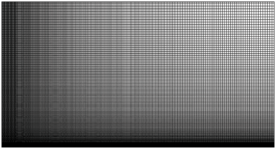
Figure 4: Mesh distribution
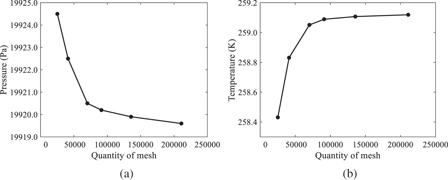
Figure 5: Solutions of pressure and temperature at coordinate (x = 50 mm, y = 0 mm) with different quantities of mesh: (a) Pressure; (b) Temperature
In order to validate the proposed atomization model, experimental results of n-pentane fuel atomization from the literature [48] are introduced as the reference solution, and the entire simulation process is illustrated in Fig. 6. The numerical solutions are compared with the experimental results in Fig. 7, where the error is within ±10%. The SMD is the average equivalent diameter, as defined in reference [48].
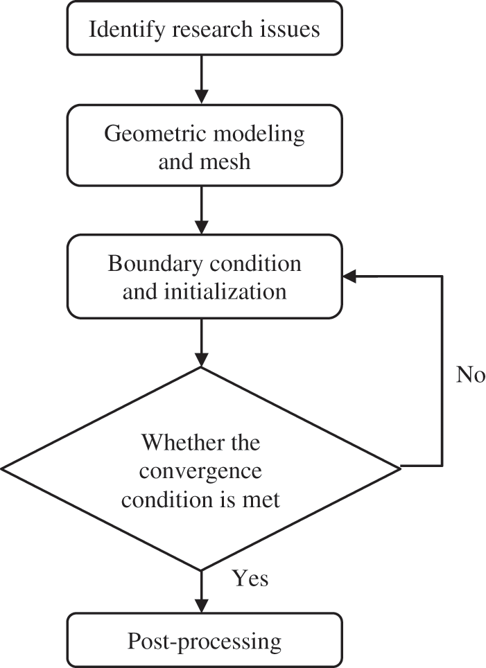
Figure 6: Simulation flow chart
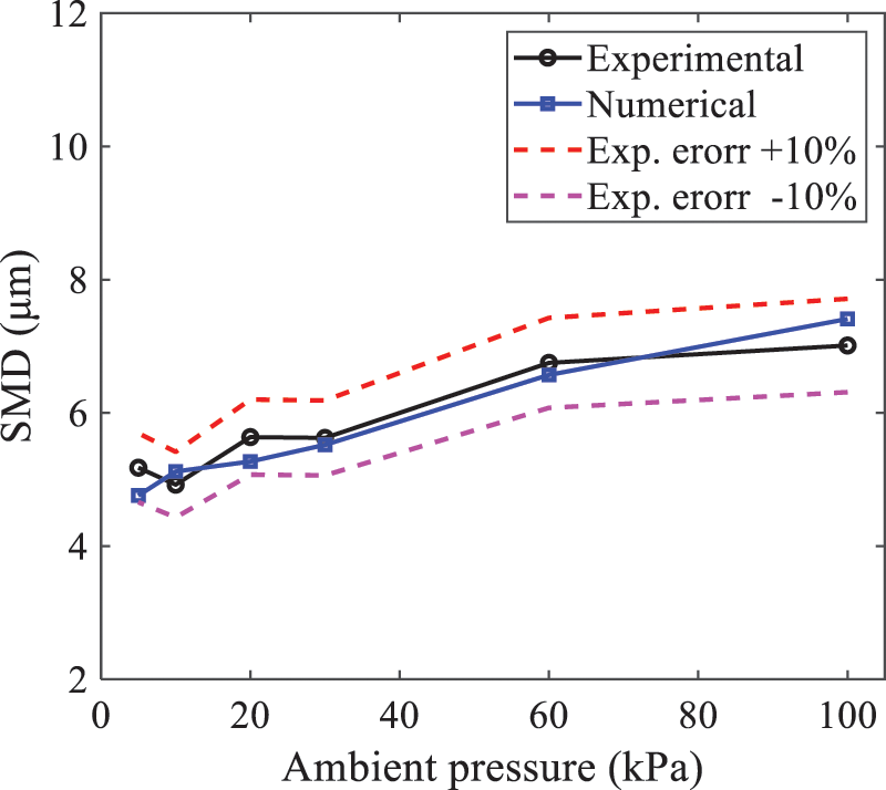
Figure 7: SMD in different ambient pressures
where
Fig. 8 displays the HFBA of fuel under an injection temperature of 379 K and ambient pressure of 60 kPa, the highest injection temperature in all the simulations presented in this work. The velocity contour reveals a microburst observable in the experiments [48], achieving a maximum exit velocity of 661.7 m/s.
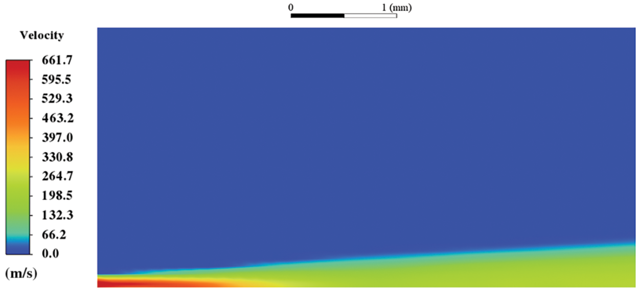
Figure 8: The velocity contour downstream of the nozzle under T = 379 K and P = 60 kPa
3.2 Analysis of the Influence Factors on Atomization Performance
For the FBA, the ambient-to-saturation pressure and the degree of superheating can be utilized as characteristic parameters to describe the phase transformation of the flash boiling spray [6,20].
3.2.1 Different Ambient Pressures
(1) Solutions of gas under different ambient pressures
As depicted in Fig. 9, when the injection temperature is set at 333 K, the velocity and temperature of the gas at positions along the x-axis gradually decrease as the ambient pressure decreases. A noticeable change is observed near the nozzle due to the intensified flash evaporation caused by the decrease in ambient pressure. Near the nozzle, more diffusion of liquid fuel occurs in the radial direction, and the droplet momentum has a larger component in the radial direction compared with traditional atomization. These dynamics result in reductions and fluctuations of velocity in the axial direction in a small region. Higher ambient pressures introduce higher velocities, although the differences are not quite pronounced. Moreover, the droplets become more dispersed due to the drop in velocity, leading to a temperature drop at the positions along the x-axis. The lower the ambient pressure, the greater the temperature change.
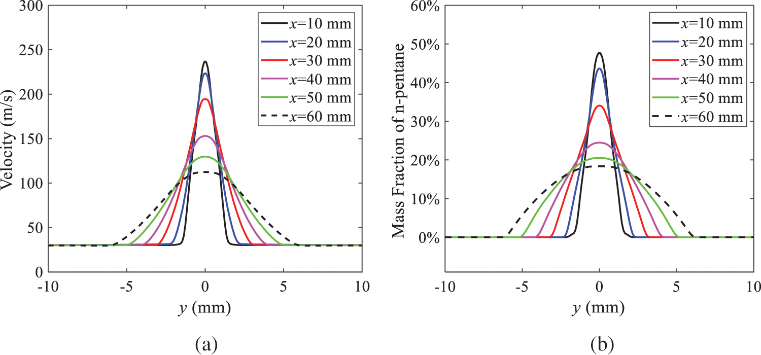
Figure 9: Velocity and temperature of the positions on the x-axis under different ambient pressures: (a) Velocity; (b) Temperature
As shown in Fig. 10, under conditions of an injection temperature of 333 K and an ambient pressure of 10 kPa, when the liquid fuel is sprayed from the nozzle into the flash chamber, the gas velocity and the fuel concentration reach their maximum values during a brief period. This occurs because the superheated liquids in the nozzle contain a large amount of internal energy, which causes the violent boiling of a large amount of liquid fuel within a specific range. The boiling generates an “explosion” that leads to a sharp increase in the velocity of the surrounding gas and enhances the fuel vapor concentration near the x-axis.
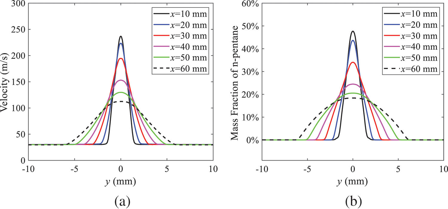
Figure 10: Velocity and mass fraction of n-pentane vapor of gas for different cross sections: (a) Velocity; (b) Mass fraction of n-pentane vapor
As the spray continues to move, the maximum velocity and vapor concentration along the x-axis direction gradually decrease while the mass fraction increases in the y-axis direction (radial direction). This phenomenon occurs since work is required to overcome air resistance during the spray motion, resulting in energy consumption. As a result, the velocity decays in both the axial and radial directions, accompanied by the diffusion of vapor in the radial direction.
(2) Solutions of droplets under different ambient pressures
In order to investigate the influence of ambient pressure on the size of atomized droplets, the SMD of droplets under an injection temperature of 333 K and ambient pressures of 5, 10, 20, 30, 60, and 100 kPa are compared, as shown in Fig. 11. The results demonstrate that the SMD of droplets tends to increase with the growth of ambient pressure.
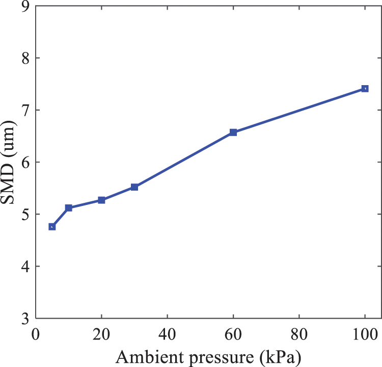
Figure 11: Variation of atomization particle size with ambient pressures
The size distribution of the droplets under ambient pressures of 5, 10, 20, 30, 60, and 100 kPa is presented in Fig. 12. The results indicate that lower ambient pressures lead to smaller droplet sizes and more concentrated particle size distributions. This is because instantaneous boiling occurs when the nozzle sprays the superheated jet liquid. Under lower ambient pressures, the saturation temperature decreases, and the liquid superheat increases, driving the flash vaporization process. In addition, the lower resistance to gas expansion in the atmospheric environment at lower pressures promotes bubble formation through boiling. The expansion force generated by these bubbles on the liquid fuel causes strong disturbance forces, further enhancing the jet’s expansion, leading to easier droplet breakup and smaller atomized SMD particle sizes.
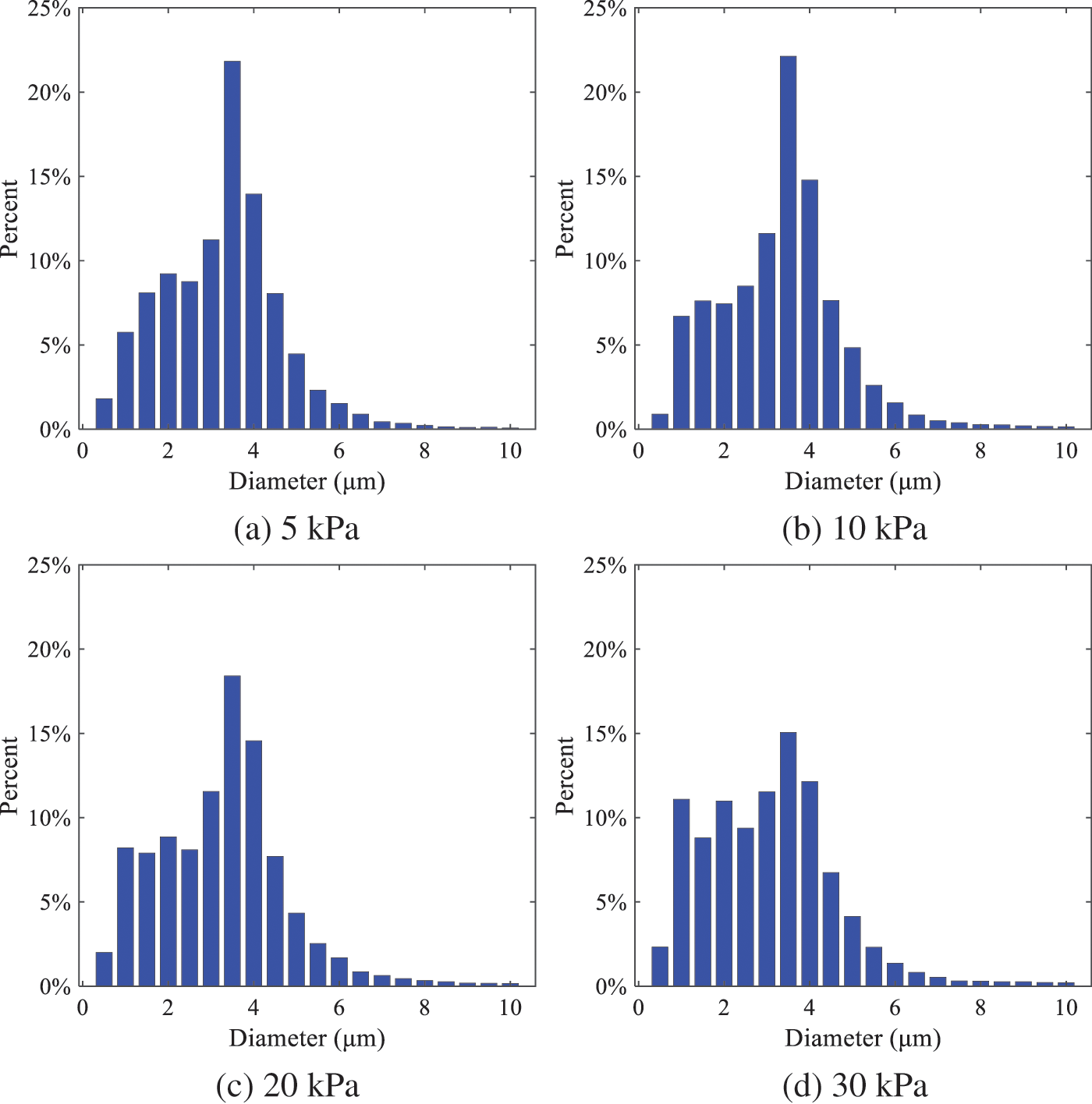
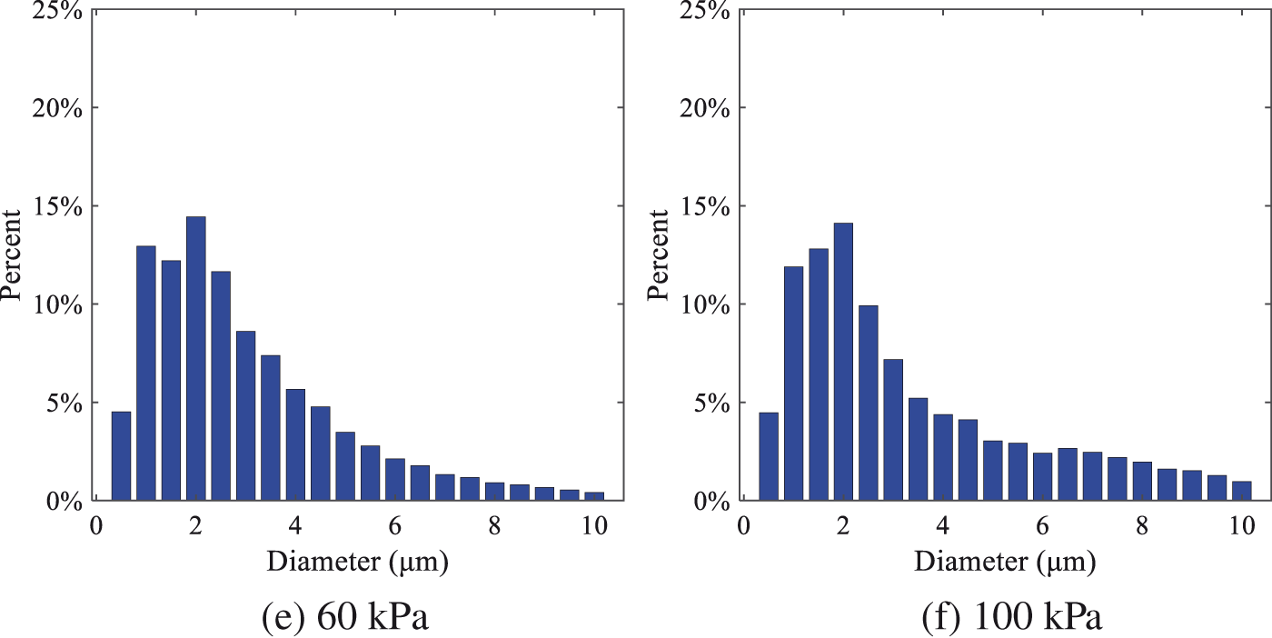
Figure 12: Distribution of particle size ratio under different ambient pressures
Fig. 13 illustrates the characteristic particle size parameters of n-pentane under different ambient pressures. D10 represents the diameter below which 10% of the liquid volume is atomized into smaller droplets, and the same applies to D30 and D50. A comparison of the results reveals that the particle size parameters, including D10, D30, and D50, are significantly smaller at low ambient pressures compared to high ambient pressures. This observation indicates that decreasing the ambient pressure is an effective way to reduce the size of atomized particles.
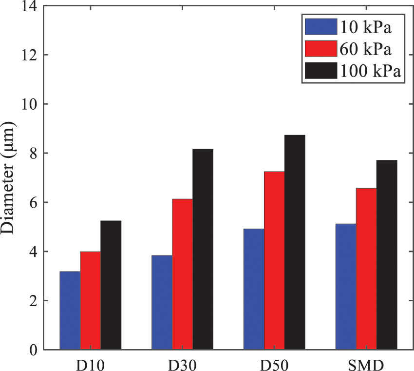
Figure 13: Characteristic parameter values of particle size under different ambient pressures
Furthermore, as displayed in Fig. 14, under an ambient pressure of 100 kPa, the percentage of droplets with a diameter of less than 5 μm is 77.1% of the total droplets formed by atomization. Under an ambient pressure of 60 kPa, this proportion increases to 85.7% and 92.2% at an ambient pressure of 10 kPa. The number of small droplets generated by the HFBA of fuel increases with decreasing ambient pressure, resulting in a higher proportion of smaller droplets. Conversely, increasing the ambient pressure leads to a higher proportion of large droplets and raises the average particle size of atomization. These results agree with the statistical results for SMD presented in Fig. 11. Therefore, reducing the ambient pressure is beneficial for liquid fragmentation atomization and can improve atomization efficiency.
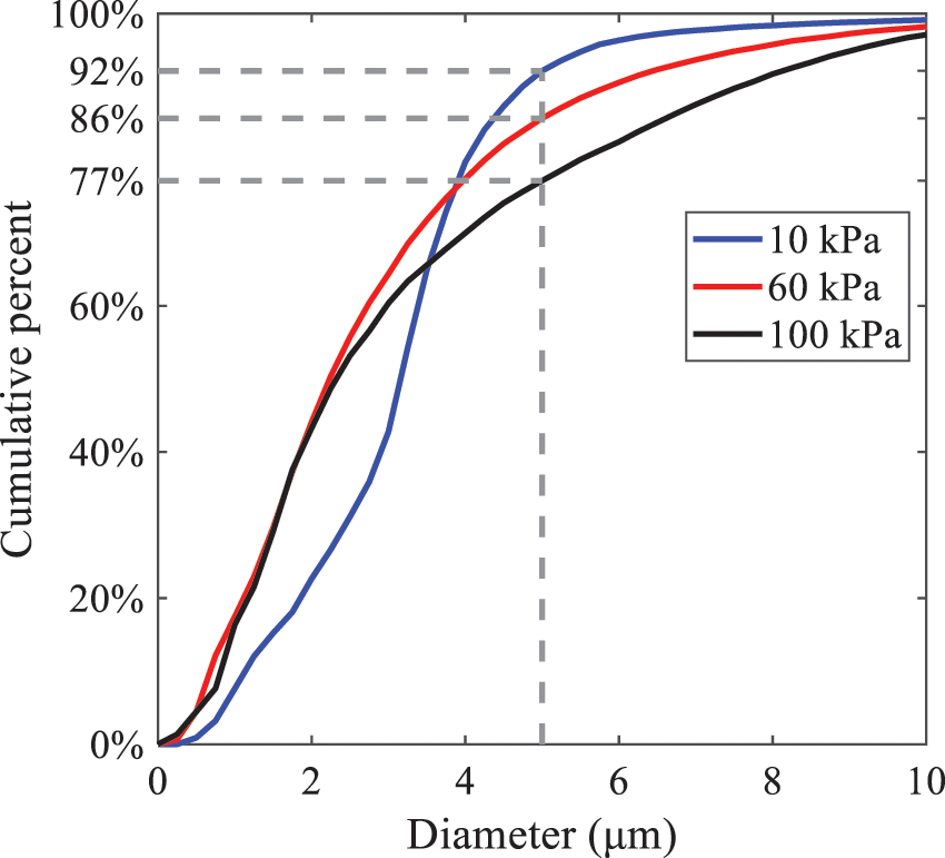
Figure 14: Cumulative distribution of droplet particle size under different ambient pressures
Fig. 15 exhibits the spray penetration depth variation in HFBA with time under different ambient pressures. As time elapses, the variation trends remain the same, but the growth rates decelerate in all three cases. As the ambient pressure decreases, the atomization becomes more violent, resulting in a “microburst effect” that causes the fuel to break into smaller droplets. These smaller droplets have less mass and volume, which disrupts the original trend of the airflow movement and reduces the axial penetration velocity. Therefore, the penetration depth of atomization spray under low ambient pressure is much smaller than that under high ambient pressure. In addition, as the ambient pressure decreases, the surface area of the total droplets increases, and overall air resistance also increases, which reduces droplet momentum and velocity. Consequently, the penetration depth is naturally reduced.
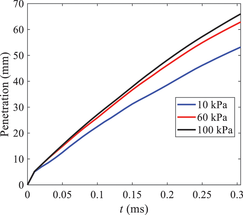
Figure 15: Penetration distance of droplets on the position of the x-axis with time under different ambient pressures
3.2.2 Different Injection Temperatures
(1) Solutions of gas under different injection temperatures
As presented in Fig. 16, when the ambient pressure is set to 60 kPa, the fuel injection velocity (velocity of the gas) increases significantly with the rise of injection temperature. At the same ambient pressure, a higher temperature results in a more pronounced flash effect, and the gas expansion leads to a higher exit velocity of the fuel. However, due to the momentum exchange with the surrounding air, this velocity gradually decreases during subsequent motion and ultimately converges to a similar velocity at x = 50 mm under different injection temperatures. Regarding the temperature distribution, liquid fuel atomization is more complete at higher injection temperatures, and the dispersed droplets accelerate the heat exchange efficiency between the droplets and surrounding air. As a result, under higher injection temperatures, a more pronounced temperature drop of the atomized droplets along the x-axis can be observed. As shown in Fig. 17, under conditions of an injection temperature of 379 K and an ambient pressure of 60 kPa, the gas velocity and the fuel concentration reach their maximum values during a brief period, where the trend is the same as in the previous section under different ambient pressures.
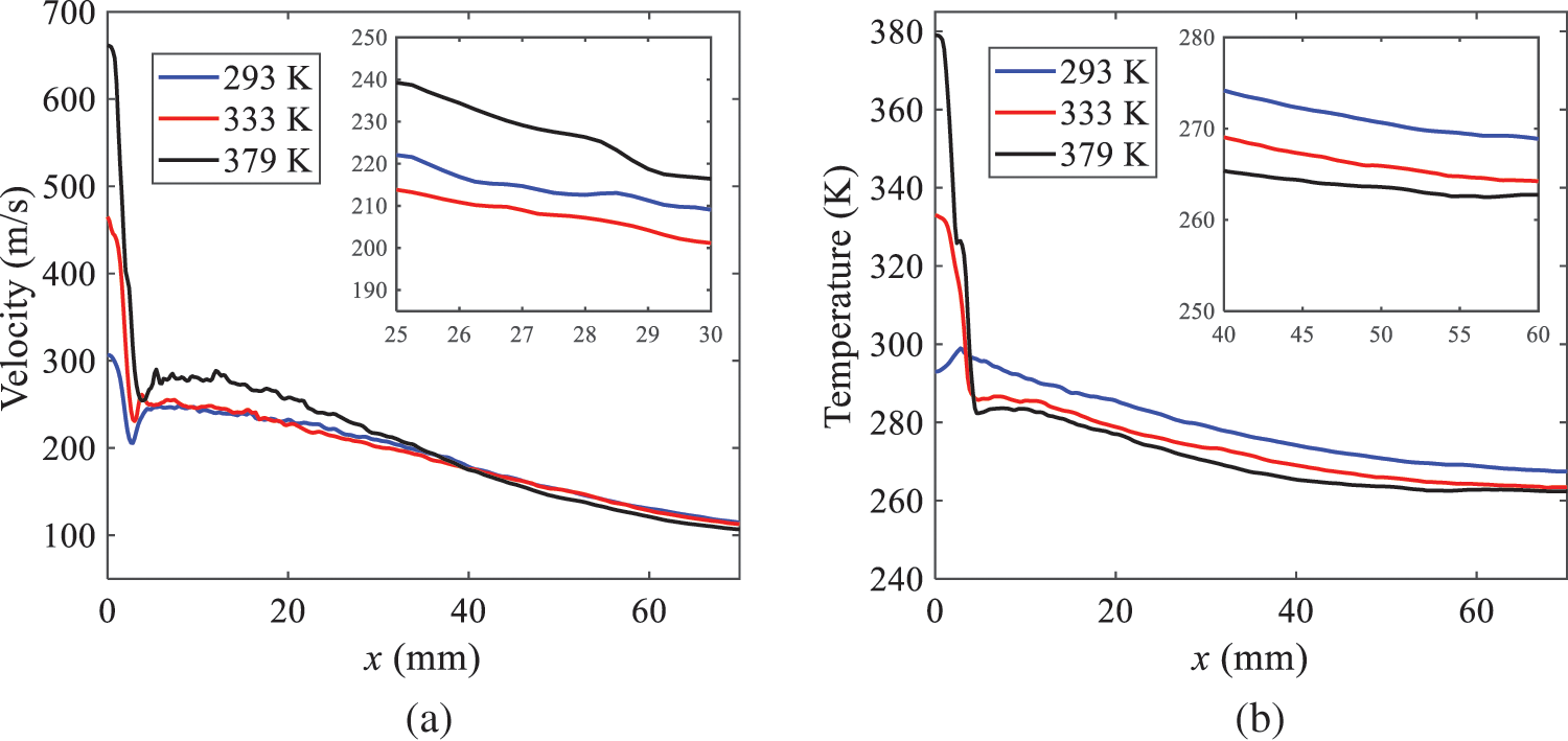
Figure 16: Velocity and temperature of the positions on the x-axis under different injection temperatures: (a) Velocity; (b) Temperature
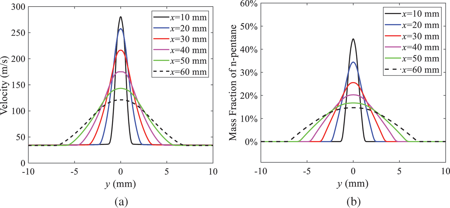
Figure 17: Velocity and mass fraction of n-pentane vapor of gas for different cross sections: (a) Velocity; (b) Mass fraction of n-pentane vapor
(2) Solutions of droplets under different injection temperatures
In order to investigate the differences in atomized droplet size at 50 mm from the nozzle under different injection temperatures, the droplet SMD at an ambient pressure of 60 kPa and injection temperatures of 293, 313, 333, 343, 353, and 397 K are compared, as presented in Fig. 18. The results agree with the available experimental data [48], which once again validates the high simulation accuracy of the proposed HFBA model.
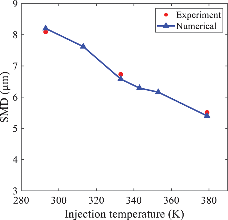
Figure 18: Variation of atomization particle size with injection temperature
As shown in Fig. 19, the SMD values of droplets decrease gradually with the increase in injection temperature. This indicates that the injection temperature can affect the atomization fragmentation. This is because a higher liquid injection temperature can result in larger evaporation under a certain flash ambient pressure. In addition, increased injection temperature promotes bubble formation and growth, which helps break up the liquid, improve liquid atomization quality, reduce the spray droplet size, and increase the flash evaporation degree. Furthermore, when the injection temperature is increased, the latent heat of the vaporization of water decreases and further facilitates the evaporation process. Therefore, increasing the injection temperature can cause the liquid fuel to break up and strengthen the atomization process. Fig. 20 displays the particle size characteristic parameters of n-pentane fuel at varying injection temperatures. The results reveal that at higher injection temperatures, the particle size parameters, including D10, D30, D50, and SMD, are notably smaller than those achieved at lower injection temperatures. This indicates that increasing the injection temperature can effectively enhance liquid fuel atomization.
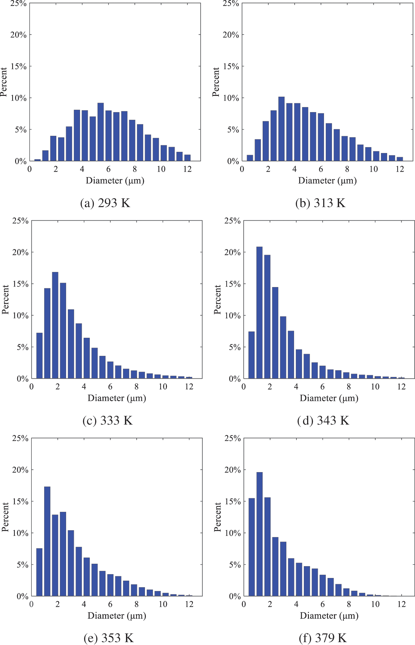
Figure 19: Distribution of particle size ratio under different injection temperatures
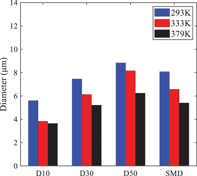
Figure 20: Characteristic parameter values of particle size under different injection temperatures
As displayed in Fig. 21, at an injection temperature of 293 K, the droplets, with a diameter of less than 8 μm formed by atomization, account for approximately 80.4% of the total number of droplets. At an injection temperature of 333 K, about 95.9% of the droplets are less than 8 μm in diameter. As the injection temperature increases to 379 K, the proportion of droplets less than 8 μm in diameter increases to approximately 98.7%. The cumulative curves for the higher temperature working conditions of 333 K and 379 K show that more than 90% of droplets are less than 6 μm in diameter, which is significantly larger than the diameter of droplets under the working condition at 293 K. These results suggest that increasing the injection temperature leads to more complete atomization, and the number of small diameter droplets continues to increase, accounting for a larger proportion. This is beneficial for the atomization process. Fig. 22 shows the atomization spray penetration depth changes over time under various injection temperatures. Although higher temperatures result in more intense flash vaporization, more pronounced radial expansion, and weaker axial expansion, the ambient temperature does not significantly affect the droplet penetration distance.
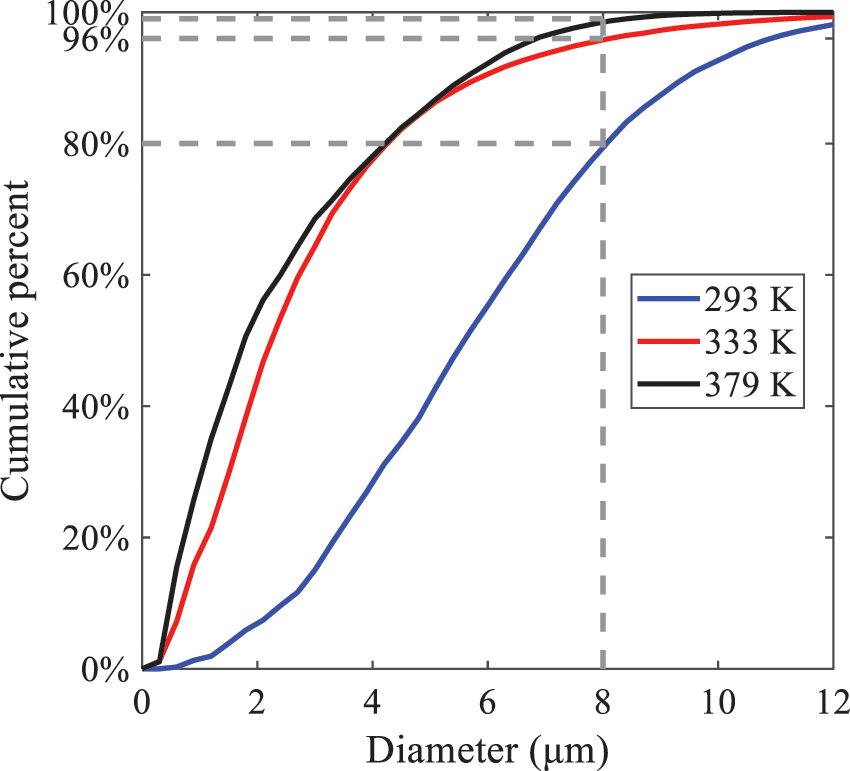
Figure 21: Cumulative distribution of droplet particle size under different injection temperatures
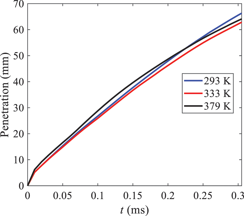
Figure 22: Penetration distance of droplets on the position of x-axis with time under different injection temperatures
This study proposes an HFBA model to simulate the atomization process under high outlet speed. Compared to the experimental results, the maximum SMD error from the proposed model is less than 8% when the numerical model’s boundary conditions align with the experiments’ operating conditions [48]. This error rate is significantly lower than the 15–20% error observed in traditional models. Utilizing fewer than one hundred thousand grids can achieve mesh-independent results, markedly more efficient than conventional simulations that require over a million grids.
The results demonstrate that HFBA can generate extremely fine and uniformly distributed spray. During flash evaporation, vapor generation and bubble growth stem from mass transfer induced by interphase heat transfer, with the vapor generation rate being regulated by thermal imbalance. Increasing the initial injection temperature or decreasing the ambient pressure enhances the liquid’s superheat, intensifies the thermal imbalance, and amplifies energy instability within the liquid, thus accelerating vapor generation. Additionally, higher superheat fosters bubble nucleation density and frequency, precipitates the onset of flash vaporization, and reduces droplet size, thereby driving the flash vapor. Incremental increases in injection temperature or reductions in ambient pressure lead to a gradual increase in the proportion of smaller droplets and a corresponding decrease in D10, D30, D50, and SMD, culminating in finer and more uniform atomized droplets. Furthermore, lowering the ambient pressure diminishes the axial velocity of atomized droplets, enhancing their combustion efficiency in the chamber. This HFBA model shows significant potential for extensive application in simulating high-velocity fuel atomization challenges.
Acknowledgement: The authors express their sincere gratitude to Professor Xuesong Li of the School of Mechanical Engineering, Shanghai Jiao Tong University, for providing invaluable insights and details crucial to the success of the experimental work in this paper. Special thanks also extend to the dedicated staff at Beijing Mechanical Equipment Research Institute for their valuable input and guidance, which contributed to the enhancement of this research. Their collaborative efforts have greatly enriched the quality and depth of their work.
Funding Statement: This work is supported by the National Natural Science Foundation of China (Project Nos. 12272270, 11972261).
Author Contributions: The authors confirm their contribution to the paper as follows: Study conception and design: Wei Zhong, Lihua Wang; data collection: Wei Zhong, Zhenfang Xin, Lihua Wang, Haiping Liu; analysis and interpretation of results: Wei Zhong, Lihua Wang; draft manuscript preparation: Wei Zhong, Lihua Wang. All authors reviewed the results and approved the final version of the manuscript.
Availability of Data and Materials: The material data utilized in this study have been sourced from Google, which provides a comprehensive platform for various datasets, and the experimental data [48] presented in this article have been cited in the main text.
Conflicts of Interest: The authors declare that they have no conflicts of interest to report regarding the present study.
References
1. Shen, S., Jia, M., Wang, T., Lü, Q., Sun, K. (2016). Measurement of the droplets sizes of a flash boiling spray using an improved extended glare point velocimetry and sizing. Experiments in Fluids, 57, 1–16. https://doi.org/10.1007/s00348-016-2147-3 [Google Scholar] [CrossRef]
2. Befrui, B., Corbinelli, G., D’Onofrio, M., Varble, D. (2011). GDI multi-hole injector internal flow and spray analysis. SAE 2011 World Congress & Exhibition. https://doi.org/10.4271/2011-01-1211 [Google Scholar] [CrossRef]
3. Payri, R., Garcia, A., Domenech, V., Durrett, R., Torres, A. P. (2012). Hydraulic behavior and spray characteristics of a common rail diesel injection system using gasoline fuel (No. 2012-01-0458). SAE World Congress & Exhibition. https://doi.org/10.4271/2012-01-0458 [Google Scholar] [CrossRef]
4. Feng, Z., Zhan, C., Tang, C., Yang, K., Huang, Z. (2016). Experimental investigation on spray and atomization characteristics of diesel/gasoline/ethanol blends in high pressure common rail injection system. Energy, 112, 549–561. https://doi.org/10.1016/j.energy.2016.06.131 [Google Scholar] [CrossRef]
5. Tian, J., Zhao, M., Long, W., Nishida, K., Fujikawa, T. et al. (2016). Experimental study on spray characteristics under ultra-high injection pressure for DISI engines. Fuel, 186, 365–374. https://doi.org/10.1016/j.fuel.2016.08.086 [Google Scholar] [CrossRef]
6. Chang, M., Lee, Z., Park, S., Park, S. (2020). Characteristics of flash boiling and its effects on spray behavior in gasoline direct injection injectors: A review. Fuel, 271, 117600. https://doi.org/10.1016/j.fuel.2020.117600 [Google Scholar] [CrossRef]
7. Bhatia, B., De, A. (2019). Flash boiling in sprays: Recent developments and modeling. Journal of the Indian Institute of Science, 99, 93–104. https://doi.org/10.1007/s41745-019-0104-x [Google Scholar] [CrossRef]
8. Wang, S., Yang, S., Qiu, S., Li, X., Hung, D. L. et al. (2022). Mechanism of flash boiling bubble breakup based on rim-like structure. Fuel, 329, 125345. https://doi.org/10.1016/j.fuel.2022.125345 [Google Scholar] [CrossRef]
9. Sher, E., Bar-Kohany, T., Rashkovan, A. (2008). Flash-boiling atomization. Progress in Energy and Combustion Science, 34(4), 417–439. https://doi.org/10.1016/j.pecs.2007.05.001 [Google Scholar] [CrossRef]
10. Liao, Y., Lucas, D. (2017). Computational modelling of flash boiling flows: A literature survey. International Journal of Heat and Mass Transfer, 111, 246–265. https://doi.org/10.1016/j.ijheatmasstransfer.2017.03.121 [Google Scholar] [CrossRef]
11. Li, S., Zhang, Y., Qi, W. (2018). Quantitative study on the influence of bubble explosion on evaporation characteristics of flash boiling spray using UV-LAS technique. Experimental Thermal and Fluid Science, 98, 472–479. https://doi.org/10.1016/j.expthermflusci.2018.03.025 [Google Scholar] [CrossRef]
12. Simões-Moreira, J. R. (2000). Oblique evaporation waves. Shock Waves, 10(4), 229–234. https://doi.org/10.1007/s001930000050 [Google Scholar] [CrossRef]
13. Vieira, M. M., Simoes-Moreira, J. R. (2007). Low-pressure flashing mechanisms in iso-octane liquid jets. Journal of Fluid Mechanics, 572, 121–144. https://doi.org/10.1017/S0022112006003430 [Google Scholar] [CrossRef]
14. Guo, H., Wang, B., Li, Y., Xu, H., Wu, Z. (2018). Characterizing external flashing jet from single-hole GDI injector. International Journal of Heat and Mass Transfer, 121, 924–932. https://doi.org/10.1016/j.ijheatmasstransfer.2018.01.042 [Google Scholar] [CrossRef]
15. Li, Y., Guo, H., Zhou, Z., Zhang, Z., Ma, X. et al. (2019). Spray morphology transformation of propane, n-hexane and iso-octane under flash-boiling conditions. Fuel, 236, 677–685. https://doi.org/10.1016/j.fuel.2018.08.160 [Google Scholar] [CrossRef]
16. Aleiferis, P. G., Van Romunde, Z. R. (2013). An analysis of spray development with iso-octane, n-pentane, gasoline, ethanol and n-butanol from a multi-hole injector under hot fuel conditions. Fuel, 105, 143–168. https://doi.org/10.1016/j.fuel.2012.07.044 [Google Scholar] [CrossRef]
17. Vu, H., García-Valladares, O., Aguilar, G. (2008). Vapor/liquid phase interaction in flare flashing sprays used in dermatologic cooling. International Journal of Heat and Mass Transfer, 51(23–24), 5721–5731. https://doi.org/10.1016/j.ijheatmasstransfer.2008.04.020 [Google Scholar] [CrossRef]
18. Lacey, J., Poursadegh, F., Brear, M. J., Gordon, R., Petersen, R. et al. (2017). Generalizing the behavior of flash-boiling, plume interaction and spray collapse for multi-hole, direct injection. Fuel, 200, 345–356. https://doi.org/10.1016/j.fuel.2017.03.057 [Google Scholar] [CrossRef]
19. Xu, Q., Pan, H., Gao, Y., Li, X., Xu, M. (2019). Investigation of two-hole flash-boiling plume-to-plume interaction and its impact on spray collapse. International Journal of Heat and Mass Transfer, 138, 608–619. https://doi.org/10.1016/j.ijheatmasstransfer.2019.04.111 [Google Scholar] [CrossRef]
20. Zeng, W., Xu, M., Zhang, G., Zhang, Y., Cleary, D. J. (2012). Atomization and vaporization for flash-boiling multi-hole sprays with alcohol fuels. Fuel, 95, 287–297. https://doi.org/10.1016/j.fuel.2011.08.048 [Google Scholar] [CrossRef]
21. Xu, M., Zhang, Y., Zeng, W., Zhang, G., Zhang, M. (2013). Flash boiling: Easy and better way to generate ideal sprays than the high injection pressure. SAE International Journal of Fuels and Lubricants, 6(1), 137–148. https://doi.org/10.4271/2013-01-1614 [Google Scholar] [CrossRef]
22. Wang, L., Qian, Z. (2020). A meshfree stabilized collocation method (SCM) based on reproducing kernel approximation. Computer Methods in Applied Mechanics and Engineering, 371, 113303. https://doi.org/10.1016/j.cma.2020.113303 [Google Scholar] [CrossRef]
23. Le-Cao, K., Mai-Duy, N., Tran, C. D., Tran-Cong, T. (2010). Towards an analysis of shear suspension flows using radial basis functions. Computer Modeling in Engineering & Sciences, 67(3), 265–294. https://doi.org/10.3970/cmes.2010.067.265 [Google Scholar] [CrossRef]
24. Wang, L., Liu, Y., Liao, Z., Zhou, Y., Yang, F. (2023). Gradient reproducing kernel based Hermite collocation method (GHCM) for eigenvalue analysis of functionally graded thin plates with in-plane material. Engineering Analysis with Boundary Elements, 148, 73–89. https://doi.org/10.1016/j.enganabound.2022.12.011 [Google Scholar] [CrossRef]
25. Loureiro, D. D., Kronenburg, A., Reutzsch, J., Weigand, B., Vogiatzaki, K. (2021). Droplet size distributions in cryogenic flash atomization. International Journal of Multiphase Flow, 142, 103705. https://doi.org/10.1016/j.ijmultiphaseflow.2021.103705 [Google Scholar] [CrossRef]
26. Zhang, Y., Ma, S., Liao, K., Duan, W. (2021). A numerical model for simulating two-phase flow with adaptive mesh refinement. Computer Modeling in Engineering & Sciences, 128(1), 43–64. https://doi.org/10.32604/cmes.2021.014847 [Google Scholar] [CrossRef]
27. Mulbah, C., Kang, C., Mao, N., Zhang, W., Shaikh, A. R. et al. (2022). A review of VOF methods for simulating bubble dynamics. Progress in Nuclear Energy, 154, 104478. https://doi.org/10.1016/j.pnucene.2022.104478 [Google Scholar] [CrossRef]
28. Vaishnavi, G. S., Ramarajan, J., Jayavel, S. (2023). Numerical studies of bubble formation dynamics in gas-liquid interaction using Volume of Fluid (VOF) method. Thermal Science and Engineering Progress, 39, 101718. https://doi.org/10.1016/j.tsep.2023.101718 [Google Scholar] [CrossRef]
29. Wen, J., Hu, Y., Nishiie, T., Iino, J., Masri, A. et al. (2022). A flamelet LES of turbulent dense spray flame using a detailed high-resolution VOF simulation of liquid fuel atomization. Combustion and Flame, 237, 111742. https://doi.org/10.1016/j.combustflame.2021.111742 [Google Scholar] [CrossRef]
30. Liu, H., Zhang, W., Jia, M., He, Y. (2018). An improved method for coupling the in-nozzle cavitation with Multi-fluid-quasi-VOF model for diesel spray. Computers & Fluids, 177, 20–32. https://doi.org/10.1016/j.compfluid.2018.09.017 [Google Scholar] [CrossRef]
31. Bureš, L., Sato, Y., Pautz, A. (2021). Piecewise linear interface-capturing volume-of-fluid method in axisymmetric cylindrical coordinates. Journal of Computational Physics, 436, 110291. https://doi.org/10.1016/j.jcp.2021.110291 [Google Scholar] [CrossRef]
32. Kumar, R., Cheng, L., Xiong, Y., Xie, B., Abgrall, R. et al. (2021). THINC scaling method that bridges VOF and level set schemes. Journal of Computational Physics, 436, 110323. https://doi.org/10.1016/j.jcp.2021.110323 [Google Scholar] [CrossRef]
33. Wen, J., Hu, Y., Nakanishi, A., Kurose, R. (2020). Atomization and evaporation process of liquid fuel jets in crossflows: A numerical study using Eulerian/Lagrangian method. International Journal of Multiphase Flow, 129, 103331. [Google Scholar]
34. Chéron, V., de Motta, J. C. B., Ménard, T., Poux, A., Berlemont, A. (2023). A coupled Eulerian interface capturing and Lagrangian particle method for multiscale simulation. Computers & Fluids, 256, 105843. [Google Scholar]
35. Zhou, W., Chen, B., Zhu, Q., Rao, S., Xu, X. (2023). Numerical simulation of angled-injected liquid jet breakup in supersonic crossflow by a hybrid VOF-LPT method. International Journal of Multiphase Flow, 166, 104503. [Google Scholar]
36. Du, B., Zhao, Z. (2021). Numerical prediction of the spray from an air-assisted fuel injection system via Eulerian-Lagrangian approach. Energy Reports, 7, 6718–6732. https://doi.org/10.1016/j.egyr.2021.09.128 [Google Scholar] [CrossRef]
37. Bi, R., Chen, C., Li, J., Tan, X., Xiang, S. (2018). Research on the CFD numerical simulation of flash boiling atomization. Energy, 165, 768–781. https://doi.org/10.1016/j.energy.2018.09.143 [Google Scholar] [CrossRef]
38. Zhou, Z. F., Lu, G. Y., Chen, B. (2018). Numerical study on the spray and thermal characteristics of R404A flashing spray using OpenFOAM. International Journal of Heat and Mass Transfer, 117, 1312–1321. https://doi.org/10.1016/j.ijheatmasstransfer.2017.10.095 [Google Scholar] [CrossRef]
39. Zhou, Z. F., Lu, G. Y., Zhu, D. Q., Zhang, L., Wang, J. F. et al. (2019). The performance of droplet evaporation model in predicting droplet dynamics and thermal characteristics for R134a single isolated droplet and two-phase flashing spray. Aerospace Science and Technology, 93, 105363. https://doi.org/10.1016/j.ast.2019.105363 [Google Scholar] [CrossRef]
40. Price, C., Hamzehloo, A., Aleiferis, P., Richardson, D. (2018). Numerical modelling of fuel spray formation and collapse from multi-hole injectors under flash-boiling conditions. Fuel, 221, 518–541. https://doi.org/10.1016/j.fuel.2018.01.088 [Google Scholar] [CrossRef]
41. Bhatia, B., De, A., Gutheil, E. (2020). Mathematical modeling of flash boiling phenomena in superheated sprays at low degree of superheat using dirichlet hyperboloids. International Journal of Multiphase Flow, 130, 103366. https://doi.org/10.1016/j.ijmultiphaseflow.2020.103366 [Google Scholar] [CrossRef]
42. Li, C., Crua, C., Vogiatzaki, K. (2019). Effect of the scale resolution on the two phase coupling characteristics of high speed evaporating sprays using LES/Eulerian-Lagrangian methodologies. International Journal of Multiphase Flow, 120, 103060. https://doi.org/10.1016/j.ijmultiphaseflow.2019.06.013 [Google Scholar] [CrossRef]
43. Duronio, F., Ranieri, S., Montanaro, A., Allocca, L., de Vita, A. (2021). ECN spray G injector: Numerical modelling of flash-boiling breakup and spray collapse. International Journal of Multiphase Flow, 145, 103817. https://doi.org/10.1016/j.ijmultiphaseflow.2021.103817 [Google Scholar] [CrossRef]
44. Asgari, B., Amani, E. (2017). A multi-objective CFD optimization of liquid fuel spray injection in dry-low-emission gas-turbine combustors. Applied Energy, 203, 696–710. https://doi.org/10.1016/j.apenergy.2017.06.080 [Google Scholar] [CrossRef]
45. Liu, X., Liu, J., Xue, R., Chen, L., Hou, Y. (2018). Heat transfer optimization of R134a phase change spray cooling in a closed loop system. Experimental Thermal and Fluid Science, 92, 248–258. https://doi.org/10.1016/j.expthermflusci.2017.11.010 [Google Scholar] [CrossRef]
46. An, Z., Xing, J., Kurose, R. (2023). Numerical study on the phase change and spray characteristics of liquid ammonia flash spray. Fuel, 345, 128229. [Google Scholar]
47. Ghiji, M., Goldsworthy, L., Brandner, P. A., Garaniya, V., Hield, P. (2017). Analysis of diesel spray dynamics using a compressible Eulerian/VOF/LES model and microscopic shadowgraphy. Fuel, 188, 352–366. https://doi.org/10.1016/j.fuel.2016.10.041 [Google Scholar] [CrossRef]
48. Li, X., Xu, Q., Qiu, S., Wang, S., Hung, D. et al. (2022). Investigations on the impact of phase change on single plume flash boiling radial expansion and drop-sizing characteristics. Applied Thermal Engineering, 202, 117911. https://doi.org/10.1016/j.applthermaleng.2021.117911 [Google Scholar] [CrossRef]
49. Munson, B. R., Young, D. F., Okiishi, T. H. (1995). Fundamentals of fluid mechanics. Oceanographic Literature Review, 10(42), 831. [Google Scholar]
50. Versteeg, H. K., Malalasekera, W. (2007). An introduction to computational fluid dynamics: The finite volume method. Second ed. Harlow, England: Pearson/Prentice Hall. [Google Scholar]
51. Gosman, A. D., Loannides, E. (1983). Aspects of computer simulation of liquid-fueled combustors. Journal of Energy, 7(6), 482–490. [Google Scholar]
52. Ranz, W. E., Marshall, W. R. (1952). Evaporation from droplets. Chemical Engineering Progress, 48(3), 141–146. [Google Scholar]
53. Ranz, W. E. (1952). Evaporation from drops. Part I and Part II. Chemical Engineering Progress, 48(4), 173–180. [Google Scholar]
54. Miller, R. S., Harstad, K., Bellan, J. (1998). Evaluation of equilibrium and non-equilibrium evaporation models for many-droplet gas-liquid flow simulations. International Journal of Multiphase Flow, 24(6), 1025–1055. [Google Scholar]
55. Sazhin, S. S. (2006). Advanced models of fuel droplet heating and evaporation. Progress in Energy and Combustion Science, 32(2), 162–214. [Google Scholar]
56. Raoelison, R. N., Koithara, L. L., Costil, S., Langlade, C. (2020). Turbulences of the supersonic gas flow during cold spraying and their negative effects: A DNS CFD analysis coupled with experimental observation and laser impulse high-speed shadowgraphs of the particles in-flight flow. International Journal of Heat and Mass Transfer, 147, 118894. https://doi.org/10.1016/j.ijheatmasstransfer.2019.118894 [Google Scholar] [CrossRef]
57. Baglietto, E., Ninokata, H., Misawa, T. (2006). CFD and DNS methodologies development for fuel bundle simulations. Nuclear Engineering and Design, 236(14–16), 1503–1510. https://doi.org/10.1016/j.nucengdes.2006.03.045 [Google Scholar] [CrossRef]
58. Zheng, X., Yang, J. (2021). CFD simulations of wind flow and pollutant dispersion in a street canyon with traffic flow: Comparison between RANS and LES. Sustainable Cities and Society, 75, 103307. https://doi.org/10.1016/j.scs.2021.103307 [Google Scholar] [CrossRef]
59. Launder, B. E., Spalding, D. B. (1972). Lectures in mathematical models of turbulence. London, New York: Academic Press. [Google Scholar]
60. Menter, F. R., Kuntz, M., Langtry, R. (2003). Ten years of industrial experience with the SST turbulence model. Turbulence, Heat and Mass Transfer, 4(1), 625–632. [Google Scholar]
61. Shih, T. H., Liou, W. W., Shabbir, A., Yang, Z., Zhu, J. (1995). A new k-ε eddy viscosity model for high reynolds number turbulent flows. Computers & Fluids, 24(3), 227–238. [Google Scholar]
62. Price, C., Hamzehloo, A., Aleiferis, P., Richardson, D. (2020). Numerical modelling of droplet breakup for flash-boiling fuel spray predictions. International Journal of Multiphase Flow, 125, 103183. https://doi.org/10.1016/j.ijmultiphaseflow.2019.103183 [Google Scholar] [CrossRef]
63. Galperin, B., Orszag, S. A. (Eds.). (1993). Large eddy simulation of complex engineering and geophysical flows. Cambridge University Press. https://doi.org/10.1016/0955-5986(96)00002-7 [Google Scholar] [CrossRef]
64. Bedford, K. W., Yeo, W. K. (1993). Conjunctive filtering procedures in surface water flow and transport. In: Galperin, B., Orszag, S. A. (Eds.In: Large eddy simulation of complex engineering and geophysical flows, pp. 513–537. New York: Cambridge University Press. [Google Scholar]
65. Reitz, R. (1987). Modeling atomization processes in high-pressure vaporizing sprays. Atomisation and Spray Technology, 3(4), 309–337. [Google Scholar]
Cite This Article
 Copyright © 2024 The Author(s). Published by Tech Science Press.
This work is licensed under a Creative Commons Attribution 4.0 International License , which permits unrestricted use, distribution, and reproduction in any medium, provided the original work is properly cited.
 Downloads
 Citation Tools