
 Submit a Paper
 Propose a Special lssue
 Open Access
ARTICLE

Multi-Scale Design and Optimization of Composite Material Structure for Heavy-Duty Truck Protection Device
1 School of Mechanical and Automotive Engineering, Guangxi University of Science and Technology, Liuzhou, 545006, China
2 Commercial Vehicle Technology Center, Dongfeng Liuzhou Automobile Co., Ltd., Liuzhou, 545005, China
3 School of Mechanical and Automotive Engineering, South China University of Technology, Guangzhou, 510641, China
* Corresponding Author: Hailiang Su. Email:
(This article belongs to the Special Issue: Structural Design and Optimization)
Computer Modeling in Engineering & Sciences 2024, 139(2), 1961-1980. https://doi.org/10.32604/cmes.2023.045570
Received 31 August 2023; Accepted 30 October 2023; Issue published 29 January 2024
 View Full Text
 Download PDF
Abstract
In this paper, to present a lightweight-developed front underrun protection device (FUPD) for heavy-duty trucks, plain weave carbon fiber reinforced plastic (CFRP) is used instead of the original high-strength steel. First, the mechanical and structural properties of plain carbon fiber composite anti-collision beams are comparatively analyzed from a multi-scale perspective. For studying the design capability of carbon fiber composite materials, we investigate the effects of TC-33 carbon fiber diameter (D), fiber yarn width (W) and height (H), and fiber yarn density (N) on the front underrun protective beam of carbon fiber composite materials. Based on the investigation, a material-structure matching strategy suitable for the front underrun protective beam of heavy-duty trucks is proposed. Next, the composite material structure is optimized by applying size optimization and stack sequence optimization methods to obtain the higher performance carbon fiber composite front underrun protection beam of commercial vehicles. The results show that the fiber yarn height (H) has the greatest influence on the protective beam, and the H1 matching scheme for the front underrun protective beam with a carbon fiber composite structure exhibits superior performance. The proposed method achieves a weight reduction of 55.21% while still meeting regulatory requirements, which demonstrates its remarkable weight reduction effect.Keywords
With the growing significance of environmental pollution and energy scarcity, and the implementation of stricter emission standards for commercial vehicles [1], the release of the “Medium and Long-Term Development Plan for the Automobile Industry” and the “National Strategy of Made in China 2025” highlights the technical direction for energy conservation and environmental protection in commercial vehicles, which emphasizes the crucial aspect of lightweight design [2]. One effective strategy is to develop and implement lightweight yet high-performance materials as alternative solutions for conventional automotive materials such as CFRP [3,4]. The FUPD of a heavy-duty truck is a passive safety device consisting of beam components installed on the frame [5]. Notably, the installation of it is a proposed method of mitigating injury to the passenger vehicle in the case of a collision [6]. As shown in Fig. 1, its design plays a crucial role in enhancing safety. Currently, the majority of protective devices available in the market are made of sheet metal, which limits their capacity for lightweight construction. As a result, the FUPD of certain heavy-duty trucks may not be adequately designed to provide sufficient strength [7]. This limitation brings challenges in meeting safety requirements and effectively safeguarding the vehicle, thereby compromising safe driving.

Figure 1: Vehicle collision at front end of truck
Due to the exceptional properties, such as light weight, high specific strength, high specific modulus and impact resistance, CFRP as an advanced composite material has been increasingly utilized in the automotive industry for lightweight structural components [3]. Recent findings indicated that the use of CFRP with different types of reinforcement can lead to a weight reduction ranging from 15% to 40% in the automotive industry [8]. Eneyw et al. [9] studied the application of CFRP material on automobile rims. The results showed that not only the weight of the rim was reduced by 80.4%, but also the effect force of the rim was reduced by 31.5%, and the total deformation rate was reduced by 15.5%. That is to say, the non-spring load of the vehicle was reduced, and the overall performance of the vehicle was improved. Jin et al. [10] used CFRP to replace the steel control arm. Under the stiffness that meets the performance requirements, the quality of the CFRP control arm was 65% lower than that of the steel control arm, and the strength, vibration characteristics and other properties had been greatly improved, and the lightweight effect is remarkable. Wang [11] have optimized the composite material design of the upper cover of the Sheet Molding Compound (SMC) composite battery pack and the lower box of CFRP battery pack for the structure of the battery pack. While achieving a high weight reduction ratio of 46.15%, the stiffness, strength and modal performance of the battery pack had been improved. Moreover, the battery pack demonstrated satisfactory performance under various working conditions, meeting the required standards. Zhang et al. [12] studied the lightweight design and optimization of CFRP floor for automobile. The results showed that the failure index of the floor was far less than the failure standard, while the mass of the CFRP floor was reduced by 6.8 kg compared with the original steel floor, which an improvement rate reaching 27.5%.
Despite the rapid development of CFRP over the past few decades, there is still a need to enhance its capability to design both microscopic component materials and macroscopic structural parameters based on the performance requirements of automotive structural parts [13]. Multiscale optimization methods play a crucial role in structural optimization as they enable the optimization of material layout, introducing a novel design model in engineering design [14,15]. However, the complexity of their structural design surpassed that of isotropic material structures, posing a significant challenge for researchers. Lv et al. [16] proposed a comprehensive optimization method that comprehensively considers fiber direction, laminate thickness and other factors to design CFRP automotive B-column with variable thickness. The results showed that considering the thickness of the laminate, it not only helped the designer to make up for the defects in the manufacturing process, but also helped to further reduce the weight by 13.33%. Li et al. [17] considered the nonlinear micro evolution of composite materials, proposed a nonlinear multi-scale analysis method, and verified it through the composite material structure of new energy vehicle battery packs. Lu et al. [18] used carbon fiber aluminum honeycomb composite material to replace the original aluminum alloy material. Using the designability of carbon fiber aluminum honeycomb composite material structure, they explored the influence of structural parameters such as the thickness of the carbon fiber aluminum honeycomb composite panel, the side length size of the aluminum honeycomb and the wall thickness of the aluminum honeycomb on. Liu et al. [19] developed a multiscale approach for predicting three-dimensional elastic model of carbon twill weave fabric composite which would be applied to crashworthiness analysis of body structure of electric vehicle.
There is limited research on the front underrun protective beams of CFRP, and there is a lack of understanding regarding the designability of CFRP in protective beams. This paper examines the fundamental characteristics of CFRP materials from a multi-scale perspective and presents a material structure matching strategy specifically for the front underrun protective beams of heavy-duty trucks. Thereinto, according to the “GB 26511-2011 Front Underrun Protection Requirements for Commercial Vehicles”, this paper explores the impact of multi-scale parameters of composite materials on the structural performance of the protective beam based on the equal stiffness design theory. Meanwhile, this study analyzes and optimizes the beam structure using Computer Aided Engineering (CAE) finite element and structural design and optimization methods under three static pressure conditions. The significance of this work is that, combined with the structural characteristics of heavy-duty truck protective beam, a novel lightweight protective beam structure using plain weave CFRP has been developed and designed.
2 Performance Analysis of CFRP Material
Material of CFRP is a multi-scale material due to its structural complexity [20]. It is made up of carbon fiber reinforced phase and resin matrix. In the case of CFRP, it can be assumed that the fiber is orthotropic anisotropic, while the matrix is an isotropic material. Thereby, the composite material as a whole behaves as an anisotropic material [21]. In engineering, it is common to use engineering constants, such as the modulus of elasticity (E), Poisson’s ratio (μ), and shear modulus (G), among other performance parameters, to characterize the elastic properties of materials. The stress-strain relationship of the CFRP can be expressed as follows:
The prediction of mechanical properties of plain CFRP is based on the properties of microscopic fibers and matrix. First, the mechanical properties of microscopic fiber yarns are calculated, followed by the calculation of mechanical properties from mesoscopic to macroscopic scale. Currently, the main theoretical formulas for predicting elastic properties of unidirectional composite materials are Chamis formula [22], Huang’s bridge [23] or Halpin-Tsai [24] model, etc. Therefore, the theoretical material parameters of fiber yarn can be calculated using the well-established theoretical model of unidirectional fiber-reinforced composites. The Chamis formula, which is based on the equal strain assumption, provides a simpler and more reliable calculation method, as shown in Eq. (2) [22].
The fiber yarn of fiber volume fraction is denoted as
The mechanical properties of composite materials exhibit nonlinearity at the macroscopic level, but periodicity at the mesoscopic level. Therefore, the overall mechanical properties of the composite can be determined by solving the representative volume element (RVE) [25]. For composites with fibers oriented in arbitrary directions, the effective modulus can be calculated using Eqs. (3) to (8) based on the spatial angle-averaged equation and the Mori-Tanaka method [26].
where
DIGIMAT-MF is a nonlinear material performance prediction tool that utilizes Eshelby’s inclusion theory and the mean field homogenization method to analyze multi-scale materials [26]. By defining the microstructure information of the composite material, such as the diameter of the reinforcing fiber and the geometric parameters of the reinforcing material, a homogenized constitutive model can be obtained. The calculation process and method are presented in Eqs. (2)–(8), and Fig. 2 illustrates the analysis process.
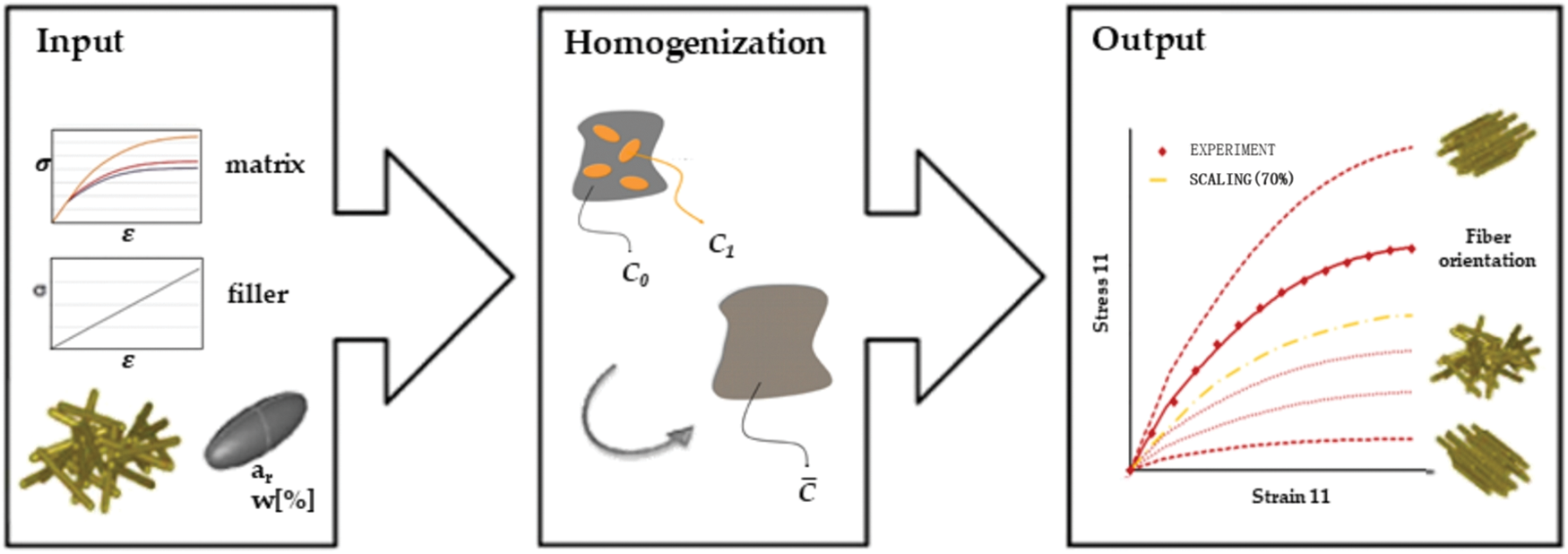
Figure 2: Flowchart of DIGIMAT-MF [26]
DIGIMAT-MF software serves as a multi-phase nonlinear material performance prediction tool. It efficiently constructs composite material models for simulation, enabling the derivation of mechanical performance.
2.2 Multi-Scale Model of Composite Materials
The mechanics of multi-scale composite materials involve considering the structural characteristics of composite materials at different scales, including macroscopic, mesoscopic, and microscopic scales [27,28]. Multi-scale analysis methods are utilized to establish the macroscopic performance of composite materials based on their component material properties and the quantitative relationship between the scales of the structure. This section helps reveal the different organization of the material at various scales, leading to the understanding of the intrinsic mechanisms behind the macroscopic performance.
The plain weave CFRP has the ability to be designed at multiple scales. It can be designed at the microstructure and mesoscopic weaving form based on the working conditions of automotive structural parts, and products can be manufactured using this woven composite material. Taking the front underrun protective beams as an example, Fig. 3 shows the schematic diagram of its structural design.
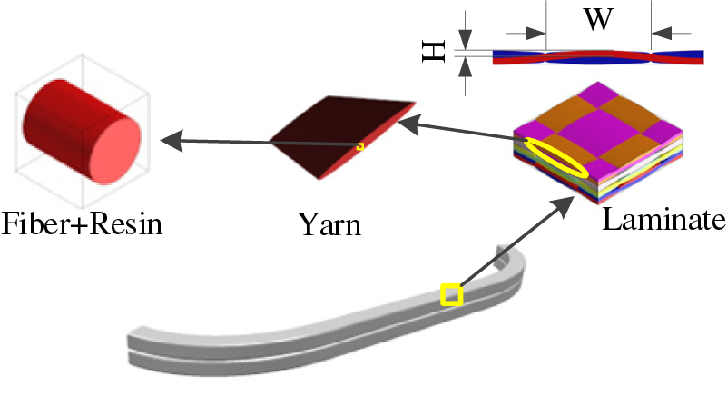
Figure 3: Multi-scale structural characteristics of FUPD
In this diagram, the microscopic scale consists of reinforcing fibers and resin matrix, the mesoscopic scale consisted of fiber yarn and resin matrix, and the laminated board represents the macroscopic structure. The design of composite materials involves these three scales, and the material parameters are influenced by each other through the homogenization method. Therefore, the design of composite materials needs to consider both material performance and structural performance, which means that material design and structural design must be carried out simultaneously.
2.3 Mechanical Properties of Plain Weave Composites
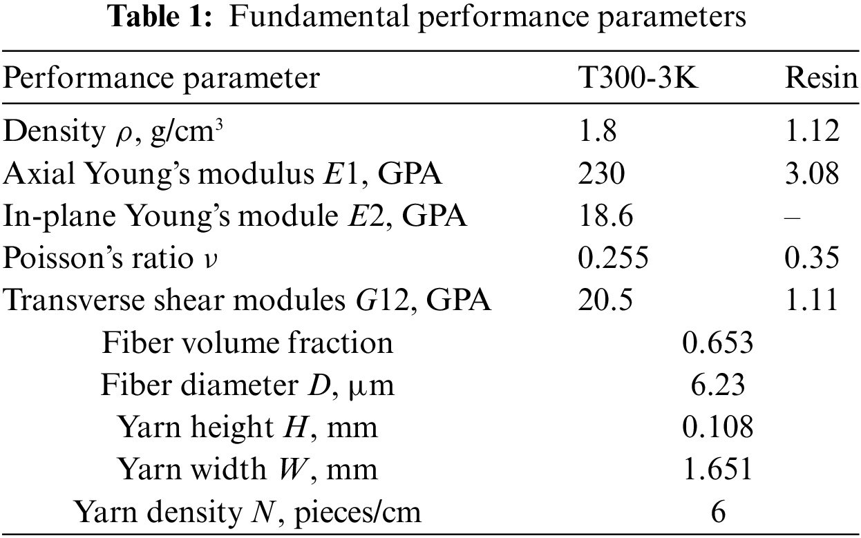
The mechanical properties of CFRP depend on the properties of its constituent materials and the volume fraction of geometric parameters. In CFRP, the fiber is served as the reinforcing phase and primarily bears the load in the composite material. The reinforced phase of CFRP investigated in this study is in the form of an ellipsoid. Table 1 presents the essential performance and geometric size parameters of both the fiber and the matrix [29]. The carbon fiber used is TC33-3K, while the matrix is composed of epoxy resin.
The mechanical properties of plain weave composites are predicted using DIGIMAT-MF, and the corresponding results are presented in Table 2.
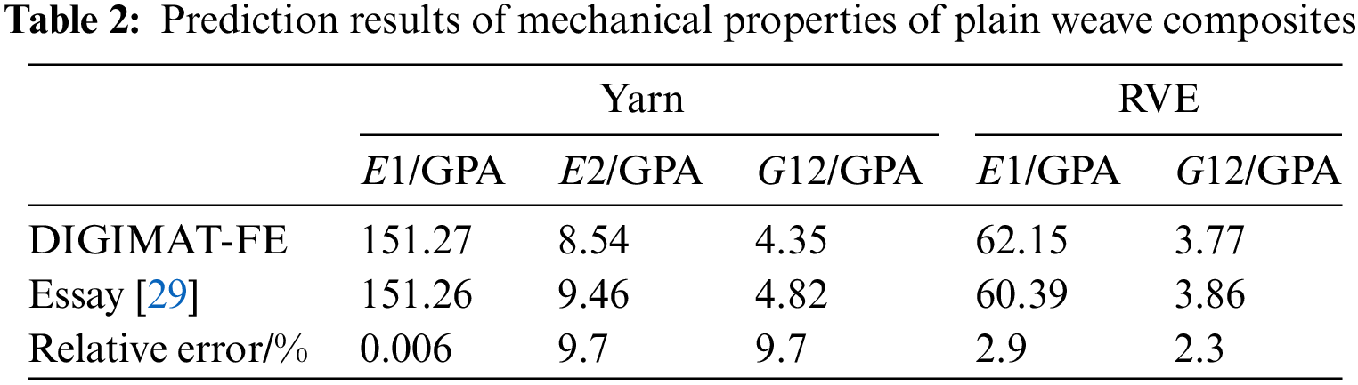
From the data presented in Table 2, it is obvious that the mechanical properties of fiber yarn E2 and G12 exhibit the highest error rate of 9.7%. On the other hand, the error rate for E1 is the lowest, measuring at 0.006%. Additionally, the error rate for the macroscopic mechanical property parameters falls within the range of 3%. It is important to consider the inherent uncertainty in the experimental process. Consequently, the parameter data obtained from the established model is utilized as the reliable performance prediction data for plain weave CFRP.
3 Performance Analysis of FUPD
The primary function of the front underrun protective device is to provide effective cushioning during car collisions, specifically to prevent passenger cars from being pulled underneath heavy-duty trucks and causing safety hazards. Currently, the front underrun protective device for heavy-duty trucks is typically made up of cross members that are either installed on the frame or other structural components. It is essential for this device to have adequate resistance against forces parallel to the longitudinal axis of the vehicle. FUPD is consisted of a cross member beam, which is also known as the protective beam, fitted at the rear of truck body through support components. As illustrated in Fig. 4, the original material is made up of high-strength steel with a thickness of 3 mm and a weight of 24.20 kg. The objective of this study is to present a lightweight-developed protective beam for a specific heavy-duty truck.
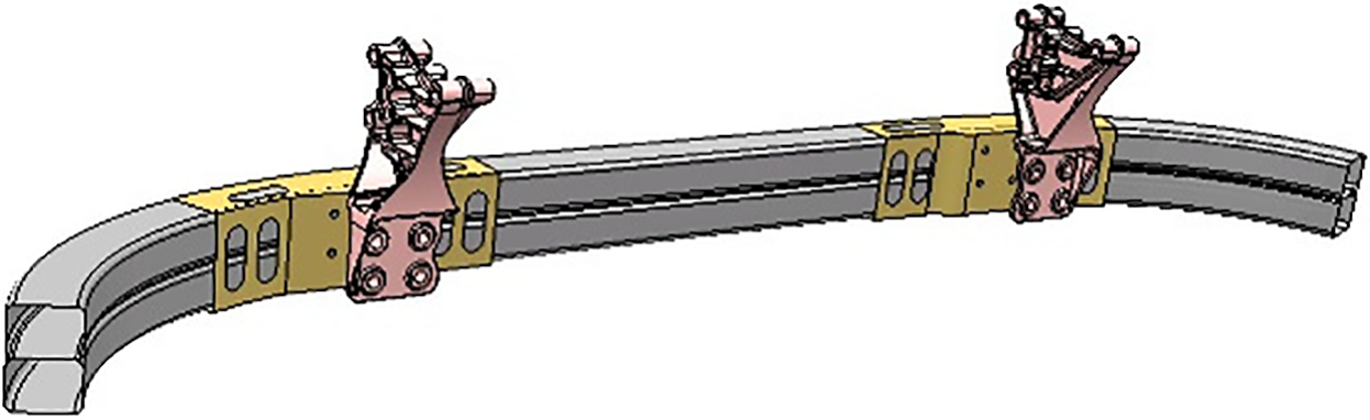
Figure 4: Constructure of FUPD
In May 2011, the National Development and Reform Commission of China released the standard GB26511-2011 Protection Requirements for Front Underrun Protection of Commercial Vehicle. This standard was based on the European norm ECE R93, which mandated the safety performance requirements for the front underrun protective devices of commercial vehicles [30]. According to the regulations, the cross member of the front underrun protective device should not be bent forward and should not have sharp outer edges. Instead, the ends should be rounded with a fillet radius of at least 2.5 mm. For N2 vehicles, the section height of the cross member should be at least 100 mm, while for N3 vehicles, it should be at least 120 mm. The objects analyzed in this paper all comply with the above regulations.
Fig. 5 illustrates the schematic diagrams of P1, P2, and P3, which represents the positions of the loading points for the three static pressure working conditions required by the regulations. Point P1 is positioned where the outermost front wheel of the vehicle is offset by 200 mm from the central axis of the vehicle. The applied load at this point is 50% of the total design weight of the vehicle, with a maximum load of 80 KN. P2 is located on the front underrun protection and is symmetrically positioned about the central axis of the vehicle. The distance between P2 and the central axis ranges from 700 to 1200 mm. The spacing of the P2 point structure is 920 mm, which meets the standard. The applied load at P2 is 100% of the designed total weight of the vehicle, with a maximum load of 160 KN. Point P3 is situated on the front underrun protection and aligns with the central axis of the vehicle. The applied load at P3 should be 50% of the total design weight of the vehicle, not exceeding a maximum of 80 KN.
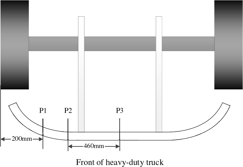
Figure 5: Loading point location diagram
To avoid the wastage of production and design resources, the FUPD is designed to be modularized and shared across different models of trucks under the same platform. In order to determine the appropriate load capacity, the maximum value among the applied loads at the three points is selected.
After completing the application of the three static load conditions, the horizontal distance between each test point on the front end of the front underrun protection and the front end of the vehicle should not exceed 400 mm. Additionally, the maximum ground clearance of the lower edge of the front lower protection between points P1 should not exceed 450 mm [31].
3.3 Equal Generation Design of Composite Materials
In lightweight design, the principle of equal stiffness design of laminate is often employed to substitute new materials in order to achieve weight reduction. The term generally refers to a construction method that replaces other materials with composite materials of the same or similar geometry without changing the load and use environment. The actual stiffness of a laminate depends on factors such as the materials used, the thickness of each layer, the angle of rotation and the order of the layers. The principle of equal stiffness during replacement can only provide a preliminary estimate of the thickness of the replaced structural member. Based on the theory of equal stiffness and design principles of laminates, a preliminary scheme of composite materials can be obtained.
This is primarily achieved by deriving a formula for calculating the thickness of the carbon fiber composite material before and after replacing the metal material [32]:
The values EC and EM represent the equivalent modulus of the carbon fiber composite laminate and the elastic modulus of the metal material, respectively. Meanwhile, IC and IM denote the section moment of inertia of the carbon fiber composite laminate structure and the interface moment of inertia of the metal structure, respectively. In the case of thin-walled structures, there is a relationship between the width of the cross-sectional area and these parameters:
Therefore, the relationship between the height (i.e., thickness) of the cross-sectional area is as follows:
According to the relevant literature, the relation between stiffness K and thickness is as follows:
where C is the geometric coefficient, E is the elastic modulus of the material, t is the thickness value of the structure, and α is the thickness index coefficient, typically ranges between 1 and 3 for automotive parts. After replacing and transforming the above formula, the thickness ratio before and after replacing the metal material with the carbon fiber composite material can be obtained:
where tC and tM denote the section thickness of the replaced carbon fiber composite structure and the section thickness of the original metal structure, respectively.
Now based on this theory, the preliminary scheme design of composite laminate is continued. In order to prevent warping deformation caused by tension-shear and tension-bend coupling, as well as reduce interlaminar stress and microcracks from curing, the CFRP-FUPD is designed with a lay-up scheme of 0°, 90°, and ±45°, ensuring a balanced and symmetrical arrangement in four ply directions [33].Furthermore, The plain weave composite material has a thickness of 0.2 mm per layer. This paper considers two schemes for the total thickness of the laminated board: α is set to 1 and 1.5, respectively. After performing the required calculations and rounding off, the thickness of CFRP-Ⅰ is determined to be 10.14 mm when α is 1, and the thickness of CFRP-Ⅱ is determined to be 6.7 mm when α is 1.5. Therefore, the preliminary preset lay-up schemes for the CFRP-FUPD beam are [0/45/90/-45]7S and [0/45/90/-45]4S, respectively. The displacement nephograms of the protective beams obtained through simulation analysis are depicted in Fig. 6.
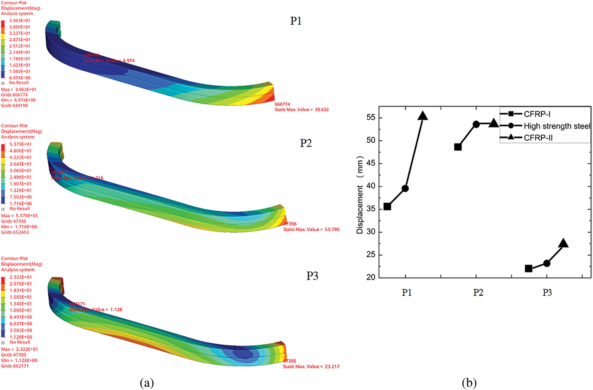
Figure 6: Simulation analysis of three static pressure conditions; (a) high-strength steel, (b) comparison of three schemes
Based on the simulation analysis, the CFRP-I scheme weighs 18.26 kg, resulting in a weight reduction of 24.55% compared to high-strength steel. The structural performance of CFRP-I is superior to high-strength steel. On the other hand, the CFRP-II scheme weighs 9.64 kg, resulting in a weight reduction of 60.16%, meeting the required performance standards. Comparing the two schemes, CFRP-II achieves a weight reduction 20.74% higher than CFRP-I. The displacement of P2 and P3 points is similar in both schemes. However, there is a notable displacement difference of 15.5 mm at the P1 point, which still falls within the acceptable range in engineering technology. It is important to note that the cost of composite materials is higher than that of steel materials, which limits its widespread use. Considering both cost and performance, this paper aims to pursue a low-cost lightweight design. What is more important is that the current approach of equal stiffness replacement does not fully optimize the performance of composite laminate structures. Therefore, the following text will analyze and optimize the CFRP-II scheme.
The preliminary scheme CFRP-II of the protective beam with the stiffness design of the laminate can meet the performance requirements of the working conditions. However, it is not the most optimal scheme as it disregards the designability characteristics of composite materials. Based on this scheme, multi-scale analysis and optimization will be carried out in the following paragraphs.
4 Multiscale Analysis of Protective Beams of CFRP
The fibers in plain weave composites are first aggregated into yarns, and then these yarns are combined with the matrix in a braided structure to form a composite material [33]. This composite material exhibits typical multi-scale characteristics. From a multi-scale analysis perspective, the fiber diameter (D) can be chosen as the design variable at the micro scale. At the meso-scale, the design variables include the width (W), height (H), and density (N) of the yarns. At the macro scale, the design variable is the layup scheme. The macro-scale design can be achieved through ply optimization. This section considers the multiscale properties of the plain weave composite and fits its material properties by considering three static loading conditions for the anti-collision beam. This is achieved by controlling variables.
4.1 Matching Analysis of Microscopic Fiber Diameter
The diameter of microscopic fibers is an important parameter that affects the volume fraction of yarn. In order to ensure the feasibility of material manufacturing, one is to insist on focusing on a single variable. In this study, the yarn width (W) was set to 1.651 mm, the yarn height (H) set to 0.108 mm, and the yarn density was set to 6 yarns/cm. A range of fiber volume fractions in the yarn are examined, specifically 55% to 75%. To study the influence of the microscopic reinforcement fiber diameter (D) on the structural performance of the protection beam, the fiber diameter is selected in an interval of 5%. The results of our analysis are shown in Fig. 7.
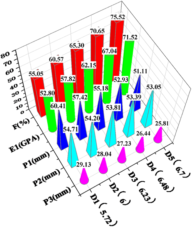
Figure 7: Data analysis of microscopic fiber diameter (mm)
It is clear from Fig. 7 that based on the analysis of the data in the table, the mechanical properties of plain weave composites exhibit a positive correlation with the yarn volume fraction. Furthermore, the displacement of the loading point of the protective beam demonstrates a negative correlation with the yarn volume fraction.
4.2 Matching Analysis of Mesoscopic Fiber Yarn Width
The effect of the mesoscopic yarn width (W) on the structural performance of the protection beam is investigated using a univariate analysis method. The microscopic fiber diameter (D) is measured to be 6.23 µm, while the yarn height is 0.108. The yarn density is determined to be 6 yarns/cm. For the yarn width (W), the considered range is [1.45, 1.65], and the length interval is selected as 0.05 for calculation and simulation analysis. The analysis results are shown in Fig. 8.
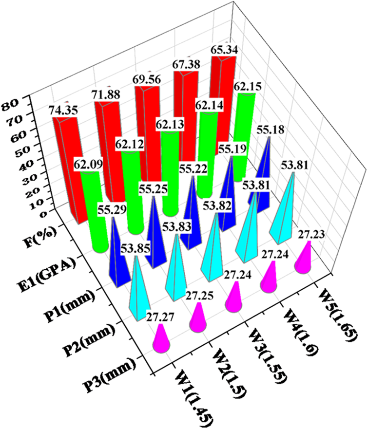
Figure 8: Data analysis of mesoscopic fiber yarn width (mm)
It can be obtained from Fig. 8 that based on the analysis of the data in the table, the width of the yarn (W) has an impact on the volume fraction of fibers in the yarn. However, it has minimal influence on the mechanical properties of the composite material.
4.3 Matching Analysis of Mesoscopic Fiber Yarn Height
In order to study the effect of the mesoscopic yarn height (H) on the structural performance of the protective beam and ensure the principle of each variable, the fiber diameter (D) is set to 6.23 µm, the yarn width (W) set to 1.651 mm, and the yarn density (N) set to 6 yarns/cm. The yarn height (H) is varied within the range of 0.08 to 0.5, with calculations and simulation analysis conducted at intervals of 0.05. The results obtained from this analysis are presented in Fig. 9.
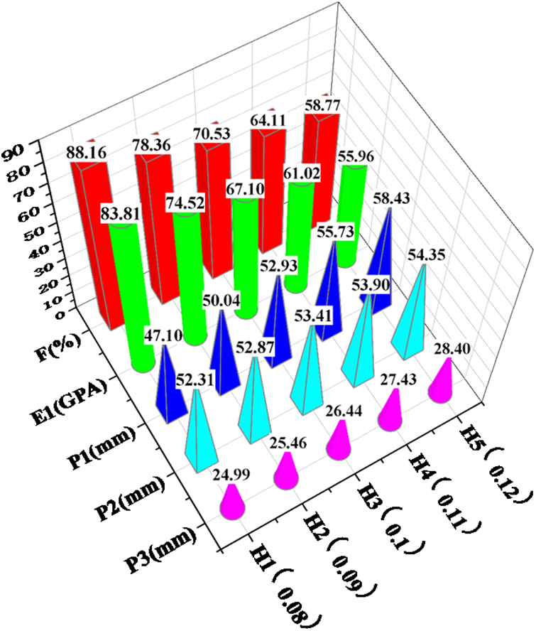
Figure 9: Data analysis of mesoscopic fiber yarn height (mm)
From the analysis of the data in the table, it is evident that the yarn height H has a more significant impact on the fiber volume fraction and plays a more prominent role in influencing the mechanical properties of composite materials.
4.4 Matching Analysis of Mesoscopic Fiber Yarn Density
To study the effect of the mesoscopic yarn density (N) on the structural performance of the protection beam, the univariate principle is necessary. In this analysis, a fiber diameter (D) of 6.23 µm, a yarn width (W) of 1.651 mm, and a yarn height (H) of 0.108 mm are considered. The number of yarns per centimeter is varied within the range of 4 to 6. A length every 0.5 for calculation and simulation analysis is selected, and the corresponding results are presented in Fig. 10.
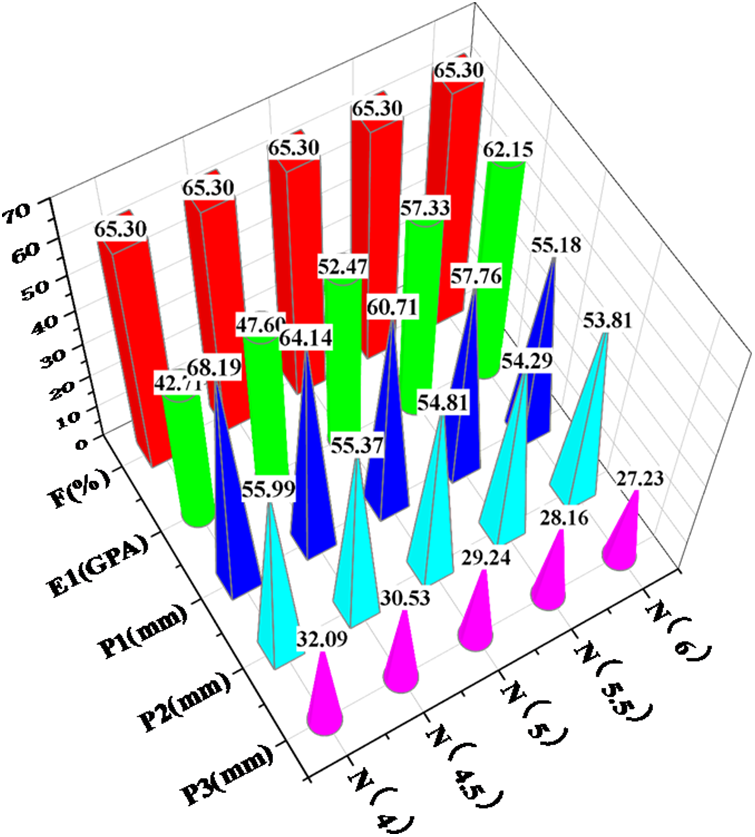
Figure 10: Data analysis of mesoscopic fiber yarn density (yarns/cm)
Based on the analysis of the data in the table, it is apparent that the impact of yarn density (N) on the mechanical properties of composite materials is second only to yarn height (H). However, it has a more significant effect on the displacement of the loading point of the protective beam.
By examining the three different load conditions of the front underrun protective beam, this study investigates the influence of various multi-scale parameters of the plain weave composite material on the structure. It is observed that each scale parameter affects both the mechanical properties of the material and the performance of the structural member. Through the comparative analysis of the matching performance of each parameter, it is determined that the H1 scheme is the most suitable material structure for the front underrun protective beam of heavy-duty trucks. The specific material parameters for this scheme are as follows: fiber diameter (D) is 6.23 µm, yarn width (W) 1.651 mm, yarn height (H) 0.08 mm, and yarn density (N) is 6 yarns/cm. This material structure fully utilizes the designability of fiber reinforced materials, resulting in not only significant weight reduction but also the improved structural performance of the front underrun protective beam.
5 Optimization Design of Composite Protection Beam Structure
In addition to analyzing and matching the plain composite materials of protective beams at the micro and mesoscopic scales, it is equally important to consider the analysis of composite materials at the macro scale. This includes examining the layup shape and stack sequence, which play a crucial role in optimizing composite materials.
The optimization of composite materials involves two main aspects: the size optimization and the stack sequence optimization [34]. The size optimization process consists of two stages: continuous size optimization and discrete size optimization. Continuous size optimization, also known as free size optimization, aims to adjust the size and shape of composite materials in order to achieve optimal structural performance within a specified design space [35]. However, the outcome of free size optimization often results in a laminated structure that has uneven thickness and an irregular shape, making it challenging to use in practical manufacturing applications. Discrete size optimization, also known as size optimization, aims to address this issue by breaking down the thickness into single-layer thicknesses that can be feasibly manufactured. And the stack sequence optimization involves adjusting the ply sequence, which has been optimized for size according to the design criteria for composite laminates. This helps improve the overall structural performance.
When optimizing the protective beam, achieving the lightest weight is a crucial factor. Therefore, while satisfying the three-point static pressure condition, it is necessary to determine the thickness, shape, and stacking sequence of the plies at each angle. This approach ensures the optimal structural performance while considering the practical manufacturing conditions.
The size optimization process involves adjusting the shape and thickness of each ply in order to achieve the best structure. The four main layers of the optimization process are set at angles of 0°, 45°, 90° and −45°. In this section, we utilize the displacement of the CFRP-H1 scheme as a constraint and aim to minimize the mass through the objective function. The mathematical model is expressed as follows:
where, M(x) is the mass function; y1, y2 and y3 are the displacement variables of P1, P2 and P3, respectively; X is the design variable; the thickness of the ‘super ply’ of carbon fiber at four classic angles, namely x1, x2, x3, x4 is 1.6 mm each. Additionally, the manufacturing constraints require that the ±45° plies exist in pairs. The free size optimization is set up according to these specifications, the thickness distribution of the optimized protective beam is shown in Fig. 11.
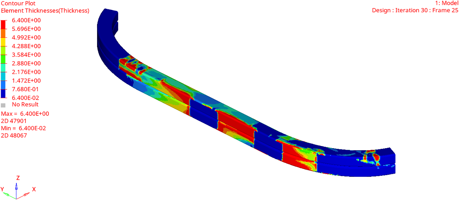
Figure 11: Shape and thickness of all layers
According to Fig. 11, the thickness of the protective beam is concentrated in the middle, except where static loading is applied. This is due to its cantilever beam structure, where reinforcing the structure at the fixed end effectively reduces displacement. The optimization result for the free size involves dividing each ‘super layer’ into four layers with different shapes and thicknesses. The total mass of this structure is only 7.54 kg. However, after optimizing the dimensions, the thickness and shape of the protective beam are not uniform, as shown in Fig. 12. This non-uniformity increases the processing and manufacturing costs and makes practical implementation difficult. Additionally, since the protective beam is symmetrical about the central axis of the vehicle, the shape of the layup needs to be corrected.
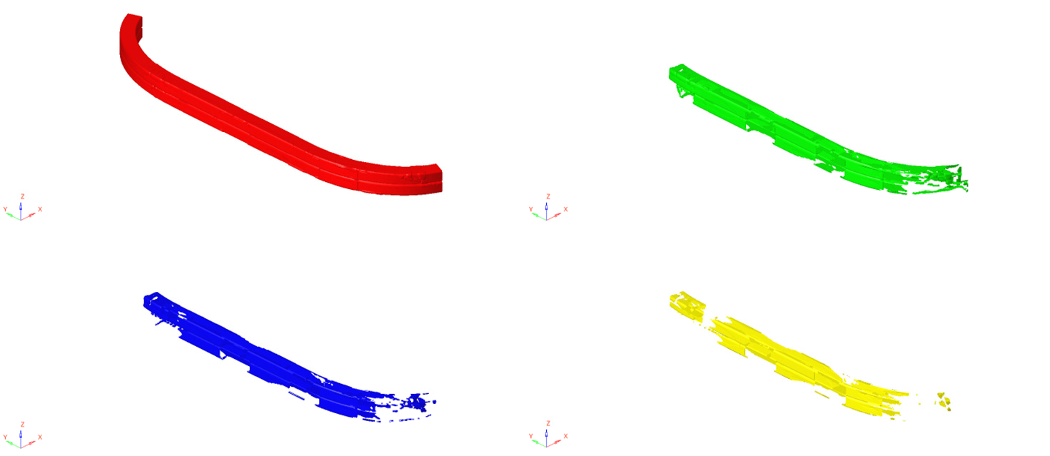
Figure 12: Shape of 0° layers
Size optimization should also take into account the practical aspects of manufacturing and process implementation. This includes adjusting the shape of the ply and determining the appropriate thickness for each ply. By observing Fig. 12, the layers at other angles are similar to these at 0°, it is apparent that the red shape depicts the entire crash beam structure, while the green shape occupies a significant portion of the beam. In contrast, the blue and yellow shapes occupy a smaller area overall. In order to ensure the structural reliability, modifications are made to the yellow and green shapes to encompass the entire structure of the protective beam, whereas the blue and yellow shapes are modified to only cover the blue area, as illustrated in Fig. 13.
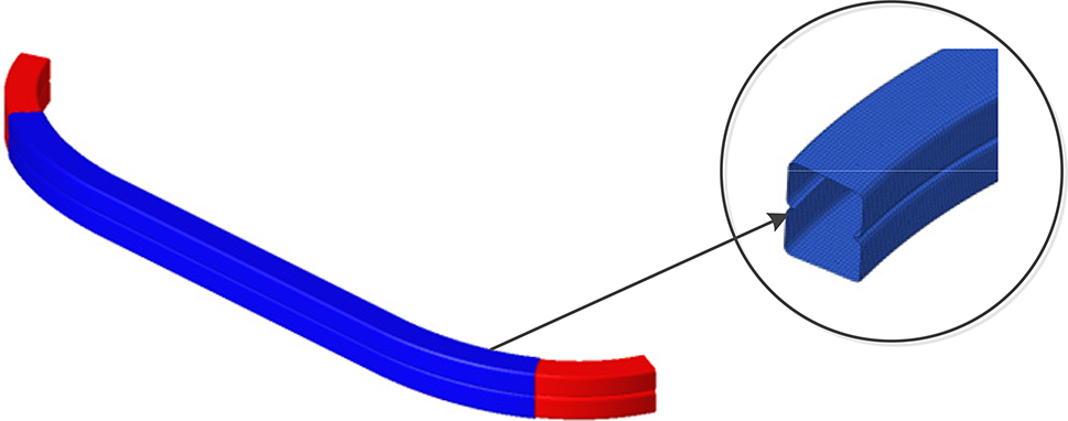
Figure 13: Corrected layer and cross-section shapes
Considering the feasibility of the manufacturing process, it is crucial to maintain a consistent thickness of 0.2 mm for each layer. After the size optimization, the laminate structure is divided into 44 layers. There are 10 layers each at 0° and 90°, and 14 layers each at ±45°. As a result, the mass of the structure reaches 10.84 kg.
5.2 The Stack Sequence Optimization
The stack sequence optimization refers to the adjustment of the ply sequence, which is optimized for size according to the design criteria in the design of composite laminates. This optimization method can be applied to the macrostructure design of composite materials and is also an important aspect of the multi-scale analysis of plain weave composite protective beams. By optimizing the stacking sequence, the mechanical properties, fatigue properties, and the impact resistance properties of composite materials can be improved. This optimization approach allows for better design and optimization of composite structures, leading to enhanced overall performance and reliability.
To determine the optimal stacking sequence, it is important to take into account additional manufacturing constraints. These constraints include maintaining the same design response as in the size optimization phase, involving no more than four consecutive layers of the same angle for delamination and one layer of delamination at 45° or −45° on the surface of the structure. After performing OPTISTRUCT iterative optimization, the resulting layup is shown in Fig. 14. The modified shape of the incomplete coverage structure is represented by the layup shape structure with a black dot in front of the number. Since the layup structure is symmetrical, only half of the layup sequences are displayed in the results.
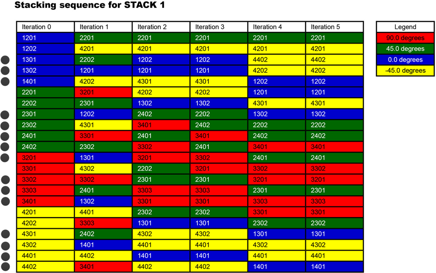
Figure 14: Optimization results of layering hierarchy
The best ply sequence obtained after three optimization iterations of ply stacking sequence optimization is [45/-45/-45/-45/0/0/-45/0/0/-45/0/45/45/90/45/90/90/45/0/-45/-45/0]s. Each layer has a thickness of 0.2 mm, which adheres to the design principles of laminated boards. Then, the optimized composite protection beam scheme CFRP-Opt is analyzed. And the displacement and mass of the initial composite scheme, the material adjustment scheme and the optimized scheme under the condition of static three-point pressure are compared. The results are presented in Table 3.
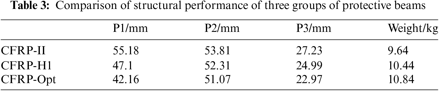
Based on the comparative analysis of the results, it was found that the micro-scale composite material analysis matching the CFRP-H1 scheme can enhance the structural performance of the protective beam. The CFRP-Opt scheme, a macro-scale optimization based on the H1 scheme, enhances the performance of composite beams. It outperforms CFRP-II and offers improved lightweight performance and reduced weight compared to CFRP-I. Finally, the multi-scale analysis and optimization scheme CFRP-Opt was identified as the most effective approach according to the composite material design criterion. This scheme not only fulfills the legal requirements of the protective beam but also reduces the mass weight by 55.21%.
This paper proposes a design method for lightweight CFRP heavy-duty truck protective beams. The method involves material matching through multi-scale analysis and optimization design of composite laminates. Within the scope of this study, the following conclusions have been drawn:
(1) The maximum error between the elastic modulus of the unit cell RVE predicted by DIGIMAT and the experimental value is 9.7%, indicating that the performance of the plain weave continuous fiber composite material predicted by DIGMAT is in line with the actual model and demonstrates good accuracy. Therefore, it can effectively meet the requirements of subsequent structural analysis.
(2) In light of the multi-scale characteristics observed in plain weave composite materials, this study proposes a matching strategy specifically tailored to the material structure of the front underrun protective beam of heavy-duty trucks. The strategy takes full advantage of the designability and unique characteristics offered by composite materials.
(3) Through the design and optimization of the composite material structure of the heavy-duty truck protective beam, it has been confirmed that the integrated design considering material, structure, and performance can effectively utilize the performance advantages of carbon fiber reinforced composite materials.
Acknowledgement: We would like to thank the authors for their contributions to this special issue. We also thank the journal of CMES for their supports for publications of this special issue.
Funding Statement: This work was supported by the Guangxi Science and Technology Plan and Project (Grant Numbers 2021AC19131 and 2022AC21140), Guangxi University of Science and Technology Doctoral Fund Project (Grant Number 20Z40).
Author Contributions: The authors confirm contribution to the paper as follows: study conception and design: Hailiang Su, Yanhui Zhang; data collection: Zhining Chen, Kaibiao Deng, Jirong Qin; analysis and interpretation of results: Hailiang Su, Lianhua Ma; draft manuscript preparation: Lianhua Ma. All authors reviewed the results and approved the final version of the manuscript.
Availability of Data and Materials: Not applicable.
Conflicts of Interest: The authors declare that they have no conflicts of interest to report regarding the present study.
References
1. Li, D., Tian, J., Shi, S., Wang, S., Deng, J. et al. (2023). Lightweight design of commercial vehicle cab based on fatigue durability. Computer Modeling in Engineering & Sciences, 136(1), 421–445. https://doi.org/10.32604/cmes.2023.024133 [Google Scholar] [CrossRef]
2. Wu, G., Chen, X., Huang, S. (2022). Comparative study on material modeling and safety of automobile front bumper. Materials Reports, 36(18), 199–205. [Google Scholar]
3. Zhang, W., Xu, J. (2022). Advanced lightweight materials for automobiles: A review. Materials & Design, 221(137), 1–20. [Google Scholar]
4. Du, B., Li, Q., Zheng, C., Wang, S., Gao, C. et al. (2023). Application of lightweight structure in automobile bumper beam: A review. Materials, 16(3), 1–25. [Google Scholar]
5. Cook, A. G., El-Gindy, M., Critchley, D. (2015). Front underride protection devices (FUPDsMulti-objective optimization. SAE International, 1(6), 509–513. [Google Scholar]
6. MacDonald, T., El-Gindy, M., Ghantae, S., Critchley, D., Ramachandra, S. (2014). Front underride protection device (FUPD) development: Design strategy with simultaneous loading. International Journal of Crashworthiness, 19(2), 196–207. [Google Scholar]
7. Xu, W. (2017). Study on collision analysis and lightweight of front underrun protective devices for commercial vehicles. China: Hubei University of Automotive Technology. [Google Scholar]
8. Ahmad, H., MA, A. A., PM, V., A, F. (2020). A review of carbon fiber materials in automotive industry. IOP Conference Series: Materials Science and Engineering, 971(3), 1–10. [Google Scholar]
9. Eneyw, G., Velmurugan, P., Habtamu, D., Ewnetu, T. C., Kumaran, S. S. (2021). Numerical analysis of reinforced carbon fiber composite material for lightweight automotive wheel application. Materials Today: Proceedings, 46, 7369–7374. [Google Scholar]
10. Jin, Z., Jiang, R., Liu, D., Sun, H. (2022). Multi-scale and multi-objective optimization of carbon fiber reinforced plastic control arm. Materials Reports, 36(S2), 111–116. [Google Scholar]
11. Wang, G. (2020). Research on lightweight design of composite battery pack for electric vehicle. China: Jilin University. [Google Scholar]
12. Zhang, S., Hao, S., Xu, L., Cai, K. (2022). Application research on the lightweight design and optimization of carbon fiber reinforced polymers (CFRP) floor for automobile. Polymers, 14(21), 1–24. [Google Scholar]
13. Bargmann, S., Klusemann, B., Markmann, J., Schnabel, J. E., Schneider, K. et al. (2018). Generation of 3D representative volume elements for heterogeneous materials: A review. Progress in Materials Science, 96(3), 322–384. [Google Scholar]
14. Wang, Y., Li, X., Long, K., Wei, P. (2023). Open-source codes of topology optimization: A summary for beginners to start their research. Computer Modeling in Engineering & Sciences, 137(1), 1–134. https://doi.org/10.32604/cmes.2023.027603 [Google Scholar] [CrossRef]
15. Chen, W., Zheng, Y., Wang, Y. (2023). Multi-objective topology optimization filled with multiple microstructures. Composite Structures, 304, 1–17. [Google Scholar]
16. Lv, T., Wang, D. (2021). Variable-thickness design of CFRP B-pillar reinforcement considering draping. Proceedings of the Institution of Mechanical Engineers, Part D: Journal of Automobile Engineering, 235(12), 1–13. [Google Scholar]
17. Li, S., Mao, Y., Liu, W., Hou, S. (2023). A highly efficient multi-scale approach of locally refined nonlinear analysis for large composite structures. Composite Structures, 306(12), 1–14. [Google Scholar]
18. Lu, Q., Shen, Q., Liu, G., Wang, X., Huang, D. (2023). Lightweight design of automobile bumper beam made of carbon fiber aluminum honeycomb composite. Modern Manufacturing Engineering, 44(3), 77–82. [Google Scholar]
19. Liu, Q., Lin, Y., Zong, Z., Sun, G., Li, Q. (2013). Lightweight design of carbon twill weave fabric composite body structure for electric vehicle. Composite Structures, 97(3), 231–238. [Google Scholar]
20. Kier, Z. T., Salvi, A., Theis, G., Waas, A. M., Shahwan, K. (2015). Estimating mechanical properties of 2D triaxially braided textile composites based on microstructure properties. Composites Part B: Engineering, 68(1), 288–299. [Google Scholar]
21. Yang, X. (2022). Simulation research on mechanical properties of 2D braided CFRP based on dynamic change of braiding angle. China: Jilin University. [Google Scholar]
22. Wali, K. C., Dyson, F. J. (1990). Mechanics of composites materials: Past, present, and future. Composites, 21(3), 271. [Google Scholar]
23. Zheng, M. H. (2000). The mechanical properties of composites reinforced with woven and braided fabrics. Composites Science & Technology, 60(4), 479–498. [Google Scholar]
24. Pan, J., Zhang, L., Liu, J., Liu, X., Zhang, G. (2023). Prediction of the elastic modulus of hybrid short fiber reinforced composites. Chinese Quarterly of Mechanics, 44(1), 133–141 (In Chinese). [Google Scholar]
25. Song, W., Krishnaswamy, V., Pucha, R. V. (2016). Computational homogenization in RVE models with material periodic conditions for CNT polymer composites. Composite Structures, 137(1), 9–17. [Google Scholar]
26. Du, B., Li, Z. X., Bai, H. M., Li, Q., Zheng, C. Q. et al. (2022). Mechanical property of long glass fiber reinforced polypropylene composite: From material to car seat frame and bumper beam. Polymers, 14(9), 1–9. [Google Scholar]
27. Gao, Z., Chen, L. (2021). A review of multi-scale numerical modeling of three-dimensional woven fabric. Composite Structures, 263(3), 1–10. [Google Scholar]
28. Bilisik, K. (2012). Multiaxis three-dimensional weaving for composites: A review. Textile Research Journal, 82(7), 725–743. [Google Scholar]
29. Xu, C., Zhu, P., Liu, Z., Tao, W. (2020). Research on multiscale stochastic mechanical properties prediction of plain woven carbon fiber composites. Lixue Xuebao/Chinese Journal of Theoretical and Applied Mechanics, 52(3), 763–773. [Google Scholar]
30. Wang, Y., Sun, S., Liu, W., Li, X. (2021). Research on the test method of the front lower protection of commercial vehicl. Frontier Discussion, 44(2), 16–17. [Google Scholar]
31. Hou, L., Tong, X., Huang, H., Li, H. (2018). Lightweight development on front-bottom protective device of the light commercial vehicle. Auto Science & Technology, 50(2), 21–26. [Google Scholar]
32. Qin, X., Ma, Q., Zhou, Q., Gan, X. (2022). Design of oil pan in carbon fiber composite material based on fibersim. Engineering Plastics Application, 50(2), 61–68. [Google Scholar]
33. Cheng, F., Zheng, C., Liu, Y., Zuo, W., Wang, X. et al. (2021). Lightweight design of CFRP-laminated structures by combining microscopical homogenization and macroscopical optimization. International Journal of Automotive Technology, 22(5), 1427–1436. [Google Scholar]
34. Liu, Z., Zhu, C., Zhu, P., Chen, W. (2018). Reliability-based design optimization of composite battery box based on modified particle swarm optimization algorithm. Composite Structures, 204(7), 1–33. [Google Scholar]
35. Zhang, J., Chen, J., Li, Z., Ji, M., Sang, T. (2020). Optimisation design of CFRP passenger car seat backplane based on impact characteristics. International Journal of Crashworthiness, 26(4), 1–13. [Google Scholar]
Cite This Article
 Copyright © 2024 The Author(s). Published by Tech Science Press.
This work is licensed under a Creative Commons Attribution 4.0 International License , which permits unrestricted use, distribution, and reproduction in any medium, provided the original work is properly cited.
 Downloads
 Citation Tools