
 Submit a Paper
 Propose a Special lssue
 Open Access
ARTICLE

Simulation of Underground Reservoir Stability of Pumped Storage Power Station Based on Fluid-Structure Coupling
1 Faculty of Architecture, Civil and Transportation Engineering, Beijing University of Technology, Beijing, 100020, China
2 College of Transportation Engineering, Nanjing Tech University, Nanjing, 210000, China
* Corresponding Author: Shuangshuang Lan. Email:
Computer Modeling in Engineering & Sciences 2024, 139(2), 1381-1399. https://doi.org/10.32604/cmes.2023.045662
Received 03 September 2023; Accepted 17 November 2023; Issue published 29 January 2024
 View Full Text
 Download PDF
Abstract
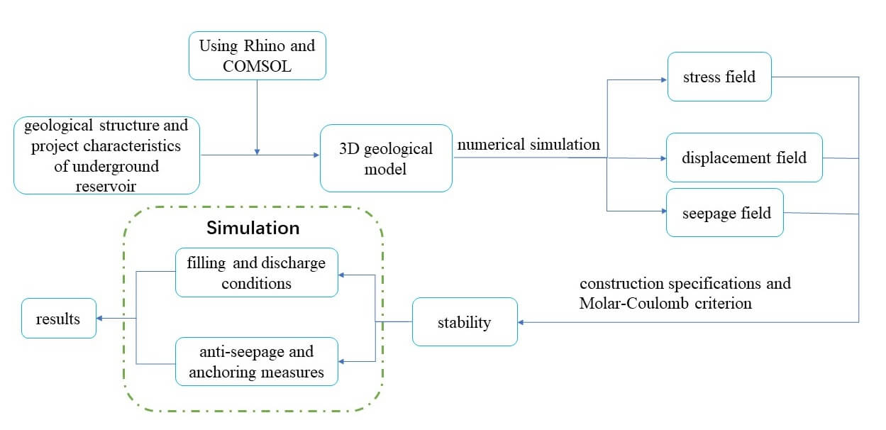
Based on global initiatives such as the clean energy transition and the development of renewable energy, the pumped storage power station has become a new and significant way of energy storage and regulation, and its construction environment is more complex than that of a traditional reservoir. In particular, the stability of the rock strata in the underground reservoirs is affected by the seepage pressure and rock stress, which presents some challenges in achieving engineering safety and stability. Using the advantages of the numerical simulation method in dealing deal with nonlinear problems in engineering stability, in this study, the stability of the underground reservoir of the Shidangshan (SDS) pumped storage power station was numerically calculated and quantitatively analyzed based on fluid-structure coupling theory, providing an important reference for the safe operation and management of the underground reservoir. First, using the COMSOL software, a suitable mechanical model was created in accordance with the geological structure and project characteristics of the underground reservoir. Next, the characteristics of the stress field, displacement field, and seepage field after excavation of the underground reservoir were simulated in light of the seepage effect of groundwater on the nearby rock of the underground reservoir. Finally, based on the construction specifications and Molar-Coulomb criterion, a thorough evaluation of the stability of the underground reservoir was performed through simulation of the filling and discharge conditions and anti-seepage strengthening measures. The findings demonstrate that the numerical simulation results have a certain level of reliability and are in accordance with the stress measured in the project area. The underground reservoir excavation resulted in a maximum displacement value of the rock mass around the caverns of 3.56 mm in a typical section, and the safety coefficient of the parts, as determined using the Molar-Coulomb criterion, was higher than 1, indicating that the project as a whole is in a stable state.Graphic Abstract
Keywords
Compared with other energy storage facilities (such as Li-ion batteries), pumped storage power stations have the advantages of a low installation cost and smaller environmental impact [1–4], and they play the roles of peak load and valley filling in the power grid system. In 2017, Germany successfully built the first pumped storage power station using an abandoned coal mine roadway (Pros Per·H). Following that, many countries started to investigate whether it would be feasible to convert a defunct mining region into a pumped storage power station [5–7]. Although some progress has been made in technical research, there is still little research on engineering stability. The engineering safety and timeliness are significantly influenced by the stability of the surrounding rock underground [8–11]. The excavation of an underground reservoir will cause the secondary stress field of the surrounding rock to change quickly, which could result in the failure of the surrounding rock [12–14]. In addition, through pore pressure and physicochemical interaction, groundwater speeds up the expansion and evolution of nearby rock fissures, worsening the degradation and destruction of the mechanical characteristics of the rock [15,16]. As a result, the coupling effect of the stress and seepage may cause serious engineering accidents [17,18]. The influence of fluid-structure (HM) coupling must be considered when analyzing the stability of the underground reservoir of a pumped storage power station.
Terzaghi's investigation of land subsidence marked the beginning of the study of the interaction between seepage and stress; Terzaghi developed a one-dimensional (1-D) consolidation model and the effective stress principle, which is the theoretical cornerstone of contemporary soil mechanics and the first model of HM coupling [19]. Boit solved the three-dimensional (3-D) consolidation problem of saturated soil based on Terzaghi's 1-D consolidation theory and also established the HM coupling equation for soil and laid the theoretical groundwork for the investigation of the HM coupling problem [20,21]. Based on the research of Terzaghi and Biot, further HM coupling model research was conducted. After Truesdell [22] introduced the concept of mixing theory in 1957, the assumptions of macroscopic homogeneity and superposition began to be applied to heterogeneous dielectric materials. Bowen [23,24] developed and improved the coupling equation system for rock mechanics within the framework of hybrid theory and proposed a typical constitutive theory of elastic stress-hydraulic hybrid. On this basis, Noorishad et al. [25] analyzed the rock consolidation theory and the porous continuum numerical model by combining the HM coupling theory and obtained the porous continuum seepage and stress coupling model. Since then, numerical codes capable of simulating HM coupling under a finite element framework have been well developed. Rutqvist and Stephansson [26] introduced a numerical model of HM coupling using the finite element technique and discussed some conceptual methods for representing the HM coupling behavior of fractured rock with an equivalent continuum. Cammarata et al. [27] used the finite element program and the Galerkin weighted residual program to study the HM coupling response in discrete assemblages of rock blocks and seepage cracks. In recent years, based on HM coupling theory and models, many scholars have conducted numerical simulations of the stability of the surrounding rock of underground engineering structures under the action of HM coupling in actual engineering projects [28,29]. In the reservoir slope stability, Maihemuti et al. [30] established an equivalent continuum mathematical model for the coupling of the seepage field and stress field and conducted an experimental study on rock deformation and failure under the coupling of seepage and stress on the reservoir slope of an open-pit coal mine hydropower station, providing a reasonable reference for solving the water-rock coupling problem.
The planned Shidangshan (SDS) pumped storage power station located in Zhenjiang City, China, was once an abandoned copper mine. Its construction can both significantly cut costs and address the area’s energy needs. It is of great significance to study the stability of the underground reservoir for the safe construction of the project. Thus, taking the SDS pumped storage power station as the research object, in this study, we established a continuum mechanical model of this area using the HM coupling theory and the numerical simulation method. Then, we simulated the characteristics of the underground seepage field, stress field, and displacement field after excavation of the underground reservoir. Finally, we analyzed the stability and timeliness of the reservoir under filling and discharge conditions, as well as the anti-seepage reinforcement. Our results provide a scientific basis for the safe operation of this future project and also provide an important reference case for the construction of other pumped storage power stations.
2 Basic Conditions of the Underground Reservoir
The planned SDS pumped storage power station is located between Nanjing City and Zhenjiang City, Jiangsu Province (119°7′16.1″ E–119°9′22.1 E, 32°8′41.4″ N–32°9′ 47.2″ N) (Fig. 1; Table S1). The project is planned to be built in an abandoned copper mine covering an area of about 6.6 km2. The abandoned roadway provides enough underground space for the construction of an underground reservoir for the pumped storage power station. The elevation difference between the upper and lower reservoirs can also be fully utilized to construct a pumped storage power station, addressing the issue of the shortage of hydraulic resources caused by the flat terrain. Furthermore, the project is located in the important power consumption areas of Zhenjiang City and Nanjing City and thus plays a key role in solving the power load problem of the entirety of Jiangsu Province.
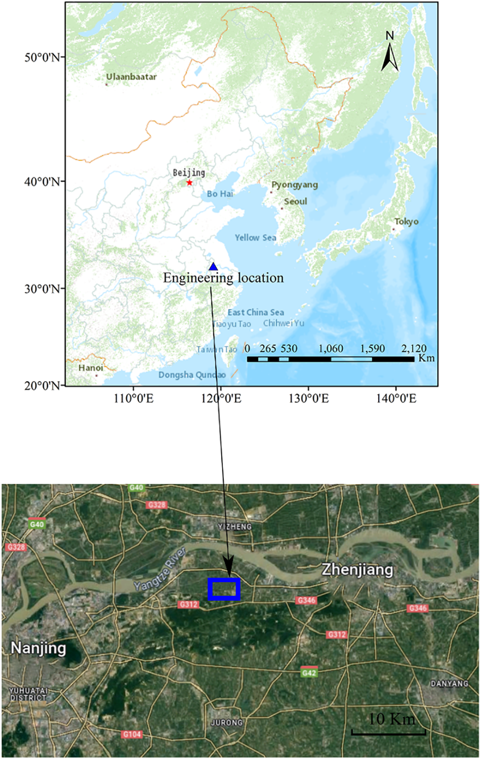
Figure 1: The triangle and rectangle represent the location of the pumped storage power station and the research area, respectively
According to the drilling data, the rock strata in this area mainly consist of Silurian to Triassic sedimentary rocks and Late Yanshan intrusive magmatic rocks (Fig. 2), which are primarily hard rock groups (quartz diorite) and reasonably hard rock groups (marble). The rocks surrounding the underground reservoir caverns are dominated by class II and class III rocks [31], the majority of which is breeze-fresh rock with little weathering. The groundwater in this region is buried at a depth of approximately 30 m, primarily as seepage into the goaf. There is no active fault in the project area, and the area has good structural stability and few engineering geological difficulties. The main components of the underground reservoir include the water storage cavity, water inlet and exit, and ventilation cavity, among others.
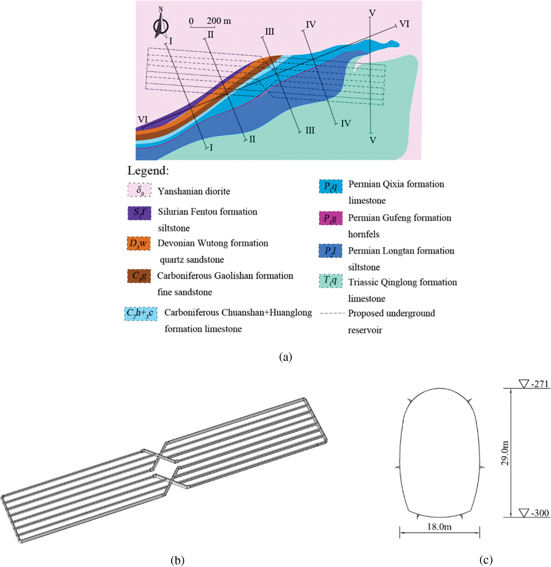
Figure 2: (a) Schematic of the strata distribution in the plane in the research area at an elevation of −300 m. I-I through VI-VI are six geological profiles with measured data that provide critical strata data for the development of this regional geological model. The dotted lines indicate the positions of the projected underground reservoir's caverns. (b) It is composed of eight parallel caverns, totaling 20,460 m in length. (c) Each cavern profile is horseshoe-shaped, with an 18 m span and a height of 29 m. The clear distance between the adjacent caverns is 42 m, and the top and bottom elevations are −271.0 m and −300.0 m, respectively
3.1 Establishment of 3-D Geological Model
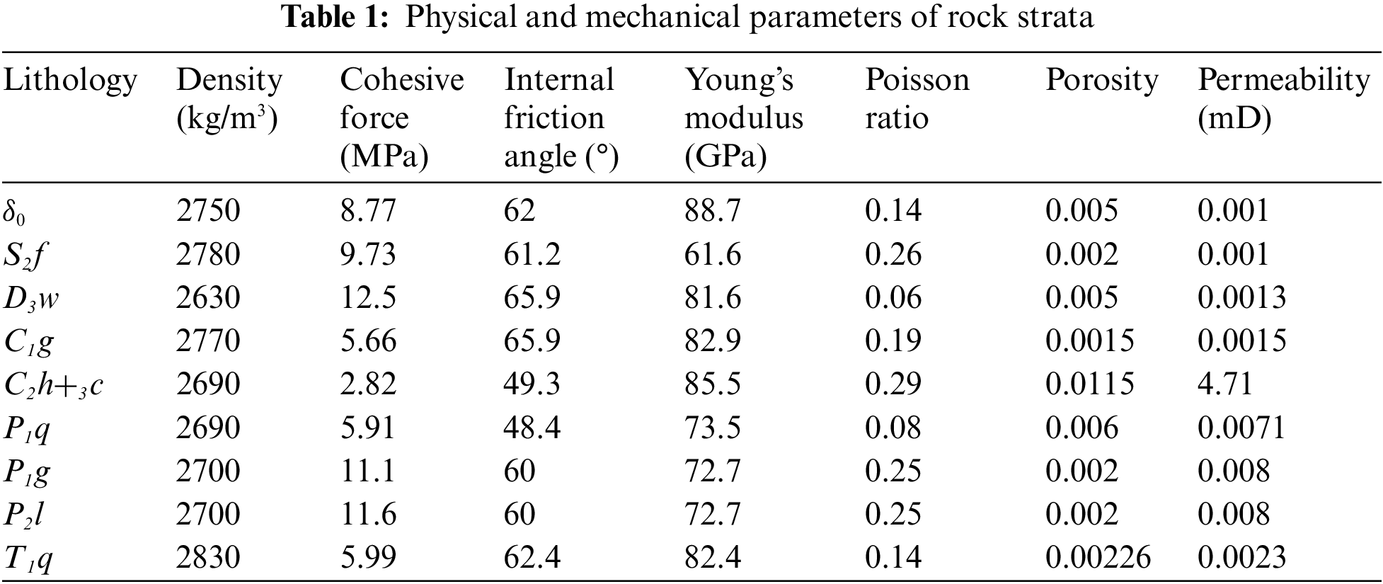
As a professional modeling software, Rhino has been widely used in the field of geological engineering. It has the advantages of a high modeling accuracy and strong operability. Therefore, the geological model was established in COMSOL with the help of Rhino software. First, the geometry without rock strata interfaces was produced using COMSOL (Fig. 3a). The surface elevation data were obtained from the Advanced Land Observing Satellite (ALOS) global 12.5 m precision digital elevation model (DEM) (https://search.asf.alaska.edu). The bottom is at an elevation of −400 m, and the sides of the geometry are vertical planes defined according to the scope of the research area. Then, based on the drilling data and geological profile (Fig. 2; Fig. S1), the rock strata interfaces were constructed in Rhino according to the corresponding spatial position (Fig. 3b). Finally, the rock strata interfaces (.stl) were successively imported into COMSOL, and the overall geometry was segmented to form a 3-D geological model containing nine domains (union) (Fig. 3c). The rock strata of each group were sampled in the field, and the samples were tested in the laboratory in accordance with the rock mass parameter test methods suggested by the International Society for Rock Mechanics (ISRM) [32], including compressive strength test, tensile strength test, elastic modulus test, Poisson ratio test and so on. Among them, two to three groups of samples were collected from each group of rock strata, and the parameters used in the model were the mean values of each group of lithologic parameters. Table 1 displays the physical and mechanical characteristics of each group of rock samples obtained through laboratory testing.
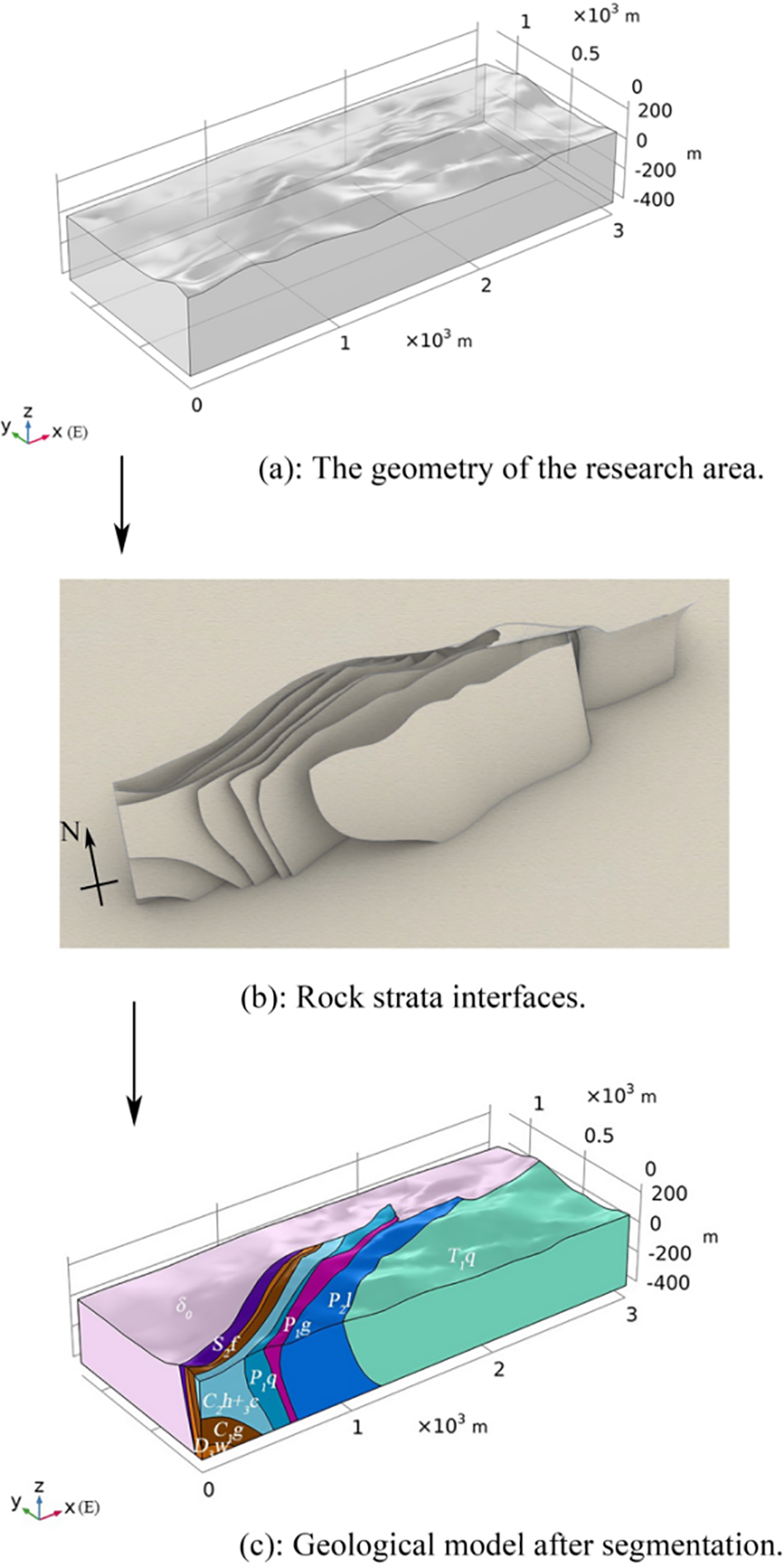
Figure 3: Construction of a 3-D geological model of the research area. The model is 3000 m long (due east direction) and 1200 m wide (due north direction), and the base elevation is −400 m. The different colors represent the different strata. The specific meanings are the same as in Fig. 2
3.2 Establishment and Solution of the Governing Equations
In the numerical simulation of the stability of the underground reservoir, the simultaneous changes in the rock mass strain and pore pressure due to the bidirectional coupling effect of the stress field and seepage field are taken into account. The corresponding equations of the physical fields are as follows.
The governing equations of stress field:
where G is the shear modulus [L−1MT−2], v is Poisson ratio, α is the Biot consolidation coefficient, p is pore pressure [L−1MT−2],
The governing equation of seepage field [33]:
where
According to the HM coupling equations, the seepage field and stress field are coupled bidirectionally with pore pressure and displacement as transfer terms. As a general multi-physics coupling simulation software [34], COMSOL finite element method has been widely used to solve multi-physics coupling problems. In this paper, Darcy’s law and solid mechanics modules corresponding to the seepage field and stress field are established respectively in the COMSOL software, and the bidirectional coupling of the seepage field and stress field is realized in the multi-physical porous elastic interface. By solving the coupling equations, the characteristics of the seepage field, stress field, and displacement field in the underground reservoir region are obtained. The geometry established using COMSOL is a union, and the mesh and physical quantities at the internal interfaces are continuous. The mesh at the interface is automatically refined by the union in the mesh division, so a solution with a relatively high precision can be obtained [35].
3.3 Initial Stress Field and Seepage Field
Before the stability analysis of underground reservoir excavation, the crustal stress field and seepage field are in a stable equilibrium state under the action of natural flow field and gravity. Based on the 3-D geological model established above, the steady state simulation of stress field and seepage field in the research area can be obtained with the help of COMSOL software, and it is used as the initial condition for the stability analysis of the underground reservoir excavation. First, the boundary conditions of the 3-D geological model are set. The bottom border of the 3-D geological model (Fig. 4) is set with no displacement, while the side boundaries have no horizontal displacement, and the upper boundary is free. The peripheral boundaries are set as the pressure head according to the measured value of the groundwater level, and the fluid is assumed to be incompressible. It is also assumed that the lower border is not a flow barrier. Before excavation, it is presumable that the underground reservoir's initial stress field and seepage field have reached a stable condition (Figs. 5a–5d). The findings indicate that the first primary stress in the research area is −7.09–1.46 MPa and that the third principal stress is −17.8–0.04 MPa before the excavation of the underground reservoir. The maximum displacement of the rock mass after reaching equilibrium under the action of gravity is 52.6 mm, which occurs at the highest elevation in the research area, and the highest pore pressure in the research area is 4.12 MPa.
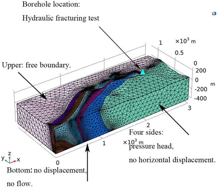
Figure 4: Three-dimensional numerical calculation model of the underground reservoir before excavation. The model has 153,208 domain elements, 29,605 boundary elements, and 1615 edge elements after mesh subdivision, and the element quality distribution is shown in Fig. S2
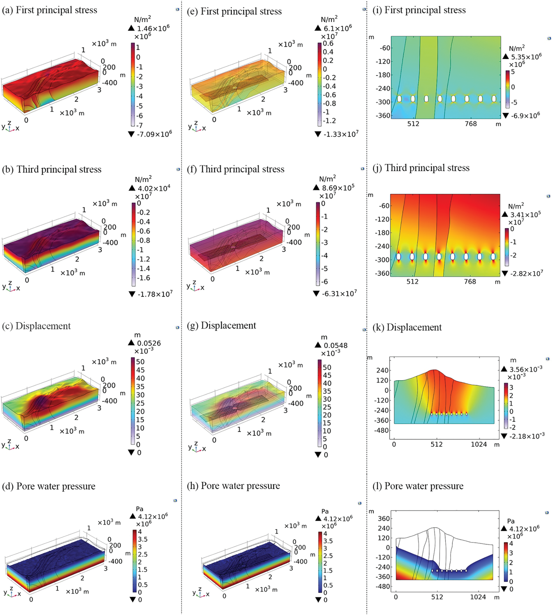
Figure 5: Three-dimensional numerical simulation results for the underground reservoir before and after excavation in the research area, including the (a–b) initial stress field, (c) displacement field, and (d) seepage field and the calculated (e–f) stress field, (g) displacement field, and (h) seepage field after underground excavation. (i–l) present the results of the 2-D calculation for the typical section (x = 1000 m) after underground excavation, including the (i–j) stress field, (k) displacement field, and (l) seepage field. To better show the change in the displacement field caused by the excavation of the underground reservoir, (k) shows the change in the displacement field after excavation relative to the initial displacement field
Hydraulic fracturing testing is one of the recommended methods for measuring rock stress issued by the ISRM in 1987 [36], and it is a direct method for measuring in-situ stress. Before the excavation of the underground reservoir, 20 in-situ stress tests were conducted at the same elevation as the reservoir in the research area. According to the test results, the maximum stress at this elevation in the horizontal direction is
3.4 Stress Field and Seepage Field after Excavation
The geometry of the underground reservoir is generated in the 3-D geological model in accordance with its spatial placement and geometric properties, and the difference set is then processed (Fig. 6). The boundary conditions of the 3-D numerical calculation model of the underground reservoir after excavation are consistent with those of the model before excavation. However, the underground reservoir is designed with exhaust holes, so the boundaries of the underground reservoir are set as free and zero pressure head boundaries. The initial conditions for the numerical simulation following excavation are the steady state conditions of the stress field and seepage field of the underground reservoir before excavation. The simulation results show that the underground reservoir can reach a new steady state after excavation, and obvious stress concentration occurs around the caverns (Figs. 5e and 5f). The zero pressure head line drops to the vicinity of the underground reservoir (Figs. 5h and 5I); that is, driven by the pore pressure, the groundwater penetrates downward in the underground reservoir.
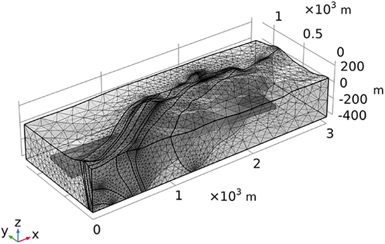
Figure 6: In the 3-D numerical calculation model of the underground reservoir after excavation, the inner mesh density is the boundaries of the underground reservoir. The model contains 359,576 domain elements, 53,881 boundary elements, and 5582 edge elements, and the element quality distribution is shown in Fig. S2
Given that the boundary conditions, mesh generation, and other variables may have an influence on the 3-D model’s correctness, in this paper, we further create a 2-D fine model at a typical profile location (x = 1000 m) in the research area and conduct more research. The section of the 3-D model can be used to determine the geometry of the 2-D model, and the rock mass's physical and mechanical properties agree with the 3-D model. The top of the model has a free boundary, the bottom has no displacement, and the two sides have no horizontal displacement. According to the measured value of the groundwater level, the two sides are established as the pressure head boundary, and the bottom is the no-flow border. The numerical simulation results show that in the typical section of the 3-D model, the first principal stress ranges from −6.69 to 5.15 MPa, the third principal stress ranges from −26.1 to 0.311 MPa, and the maximum displacement around the caverns is 3.42 mm (Fig. S3), which are similar to the 2-D numerical simulation results (the first principal stress ranges from −6.9 to 5.35 MPa, the third principal stress ranges from −28.2 to 0.341 MPa, and the maximum displacement around the cavern is 3.56 mm). The displacement mostly affects the top and bottom of the caverns in the underground reservoir, and the displacement on both sides is minimal.
4.1 Stability Analysis after Excavation
Currently, because the factors affecting the stability of the underground reservoir are very complex, there has not been a consistent method for evaluating the stability of the surrounding rocks [37,38]. In this paper, the stability of the underground reservoir of the pumped storage power station is thoroughly evaluated based on the results of the numerical simulation (stress and displacement), the Mohr-Coulomb criterion, and the construction specifications of the nation (Technical code for engineering of ground anchorages and shotcrete support (GB 50086-2015)) in which the project is located. The material yields in accordance with the Mohr-Coulomb yield criterion when the stress state reaches the following thresholds:
where
When
Then:
Based on this, the yield surface equation can be written as:
where
From above, the factor of safety defined by Mohr-Coulomb yield criterion in the stress space can be expressed as:
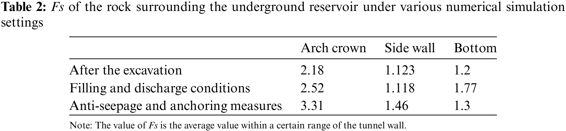
After the excavation of the underground reservoir, the displacement of the surrounding rock mass around the caverns ranges from 0.1 to 3.56 mm, which are substantially less than the maximum displacement permitted by local national standards (approximately 50.4 mm). Additionally, each component's factor of safety, as determined by the Mohr-Coulomb criterion, is greater than 1, further indicating that the entire underground reservoir is stable and safe after excavation.
4.2 Stability Analysis of Filling and Discharge Conditions
During the operation of the pumped storage power station, the frequent filling and discharge of the underground reservoir with water may affect the local stress field, resulting in deformation and destruction of the surrounding rock mass. Therefore, the stability of the underground reservoir under filling and discharge conditions is numerically simulated under the condition when excavation anti-seepage measures are considered in the actual project; that is, the boundaries of the underground reservoir are set as impervious. The draining and filling of the underground reservoir are assumed to be possible working conditions, the bottom of the reservoir is regarded as the dead water level (−300 m), and the arch of the reservoir is regarded as the maximum storage water level (−271 m); that is, the water level fluctuates between −300 and −271 m under the operation conditions of the underground reservoir (Fig. 7).
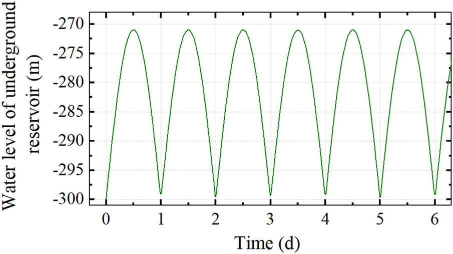
Figure 7: Filling and discharge conditions of the underground reservoir. At the initial time (t = 0 d), there is no water in the reservoir, and the water level is −300 m. At t = 0.5 d, the reservoir is filled with water, and the water level is −271 m. At t = 1 d, the reservoir is drained, and the water level is restored to −300 m
Considering the connection between the underground reservoir and the atmosphere, as well as the timely implementation of anti-seepage measures during the excavation process, there is no hydraulic exchange at the boundaries of the underground reservoir in the numerical simulation under the filling and discharge conditions. In addition, the pressure head can be transformed into the boundary load and can change over time. When the groundwater depth is 29 m, the maximum load generated is 0.29 MPa. According to the operating conditions shown in Fig. 7, the stability of the underground reservoir after 10 years was numerically simulated using an operation cycle of 1 day and considering anti-seepage measures (Figs. 8a–8d). It can be seen that the effect of the water pressure increases the factors of safety of the arch crown and cavern bottom. Compared with the steady state without any protective measures (Fig. 5k), the side wall's factor of safety decreases from 1.123 to 1.118 under the influence of the pressure cycle, a reduction of 0.44%. The maximum displacement of the arch crown decreases from 3.56 to 3.3 mm, a decrease of 7.3%; and the maximum displacement of the arch bottom increases from 2.18 to 3.09 mm, an increase of 41.74%.
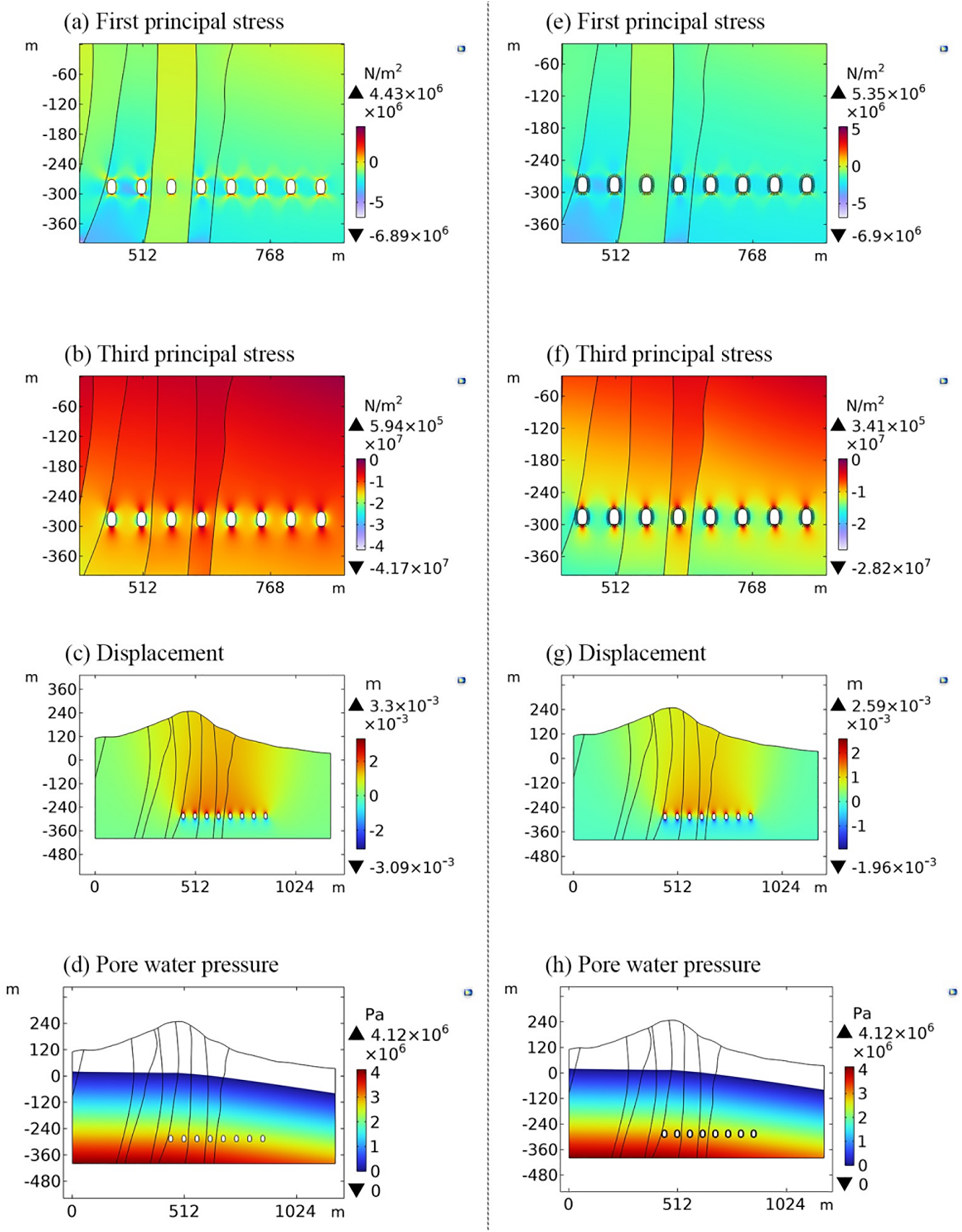
Figure 8: Numerical simulation results of the stress field, displacement field, and seepage field in a typical section. Images (a–d) present the results for underground reservoir operation for 10 years under the filling and discharge conditions with anti-seepage measures. Images (e–h) present the results for a steady state underground reservoir with simultaneous anti-seepage and anchoring measures
4.3 Stability Analysis of Anti-Seepage Anchorage Measures
For unsafe phenomena such as rock bursts that may occur in underground engineering, the common treatment measures include bolt support and concrete lining, among others. In this paper, a straightforward anti-seepage anchorage measure was simulated. The steel bars used for anchoring have a prestressing force of 1000 KN, a diameter of 28 mm, a length of 6.5 m, and a bar spacing of 2 m. In Figs. 8e–8h, the impacts are also illustrated. The results show that the safety factors of the side wall and bottom increase from 1.2 to 1.3 and from 1.123 to 1.46, respectively, when the subterranean reservoir reaches a stable condition following anti-seepage anchoring (Table 2). The maximum vault displacement decreases from 3.56 to 2.59 mm, by 27.25%, compared with the situation without any measures (Fig. 5k). The arch bottom's maximum displacement decreases from 2.18 to 1.96 mm, by 10.09%.
4.4 Sensitivity Analysis of Parameters
The chosen rock mechanics parameters frequently have an influence on the effectiveness of the numerical simulation method in the stability analysis of underground engineering. The rock mass characteristics measured via laboratory and field experiments may be slightly different from the actual rock mass because the surrounding rock is affected by the mineral structure and geological structure, which results in a great deal of spatiotemporal variability in its mechanical behavior. Considering that Young’s modulus and Poisson ratio are two important parameters that reflect the deformation degree of a rock mass under stress, in this paper, we examine the sensitivity of Young’s modulus and Poisson ratio to the surrounding rock by using the caverns in the S2f rock formation as the research object and the maximum primary compressive stress around the caverns as the evaluation index. As shown in Fig. 9, the coefficients of variation of Young’s modulus and Poisson ratio are 0.1, which means that the other characteristics of the rock mass are unaffected, while Young's modulus can vary between 55.44 and 67.76 MPa, and the Poisson ratio can vary between 0.234 and 0.286. According to the results of the parameter sensitivity analysis, the maximum main compressive stress of the rock surrounding the cavity is more sensitive to Young’s modulus than to the Poisson ratio. Therefore, when determining the maximum compressive stress of the surrounding rock following underground engineering excavation, special attention should be paid to Young’s modulus.
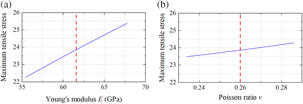
Figure 9: Results of the analysis of the sensitivity of the maximum compressive stress around the cavern to (a) Young’s modulus and (b) Poisson ratio, E = 61.6 MPa, v = 0.26
Taking into account the bidirectional coupling effect of the stress and seepage of porous media, in this study, we used the finite element method in COMSOL to conduct numerical simulations of the stability of the rock surrounding an underground reservoir after excavation and under the operating conditions, and we analyzed the stability and efficiency of the underground reservoir. Due to the good geological conditions of the site, the deformation of the surrounding rock of the underground reservoir is small, and no damage has occurred after the excavation. Even when only anti-seepage measures are considered, the cavern remains stable after 10 years under the filling and discharge conditions. In addition, it was found that the anti-seepage anchorage measures are very effective in reducing the tension stress around the cavern and the deformation of the surrounding rock. Inevitably, in the numerical simulation, the same rock strata are regarded as a homogeneous isotropic material in the stability analysis of the surrounding rock of the cavern, which may lead to some deviation of the simulation results from the actual situation. In addition, because the distribution of the faults and cracks in the project region is quite sparse, their influence on the outcomes was ignored in this numerical simulation. However, the findings of this study can still be used as a general guide for managing and operating projects safely in the future.
Acknowledgement: Thanks to Dr. Mingqian Li for his careful guidance on model construction in this study. And thanks to Dr. Baoming Chi for providing relevant geological data and guiding the paper in the revision process.
Funding Statement: This study is funded by the Beijing Natural Science Foundation of China (8222003) and National Natural Science Foundation of China (41807180).
Author Contributions: The authors confirm contribution to the paper as follows: study conception and design: Hongbiao Gu; data collection: Zhengtan Mao; analysis and interpretation of results: Peng Qiao; draft manuscript preparation: Peng Qiao and Shuangshuang Lan. All authors reviewed the results and approved the final version of the manuscript.
Availability of Data and Materials: All relevant data are within the paper and its Supplementary Materials files.
Conflicts of Interest: The authors declare that they have no conflicts of interest to report regarding the present study.
References
1. Wong, I. H. (1996). An underground pumped storage scheme in the Bukit Timah granite of Singapore. Tunnelling and Underground Space Technology, 11(4), 485–489. https://doi.org/10.1016/s0886-7798(96)00035-1 [Google Scholar] [CrossRef]
2. Kucukali, S. (2014). Finding the most suitable existing hydropower reservoirs for the development of pumped-storage schemes: An integrated approach. Renewable & Sustainable Energy Reviews, 37, 502–508. https://doi.org/10.1016/j.rser.2014.05.052 [Google Scholar] [CrossRef]
3. Minakshi, M., Mitchell, D. R. G., Jones, R. T., Pramanik, N. C., Jean-Fulcrand, A. et al. (2020). A hybrid electrochemical energy storage device using sustainable electrode materials. Chemistryselect, 5(4), 1597–1606. https://doi.org/10.1002/slct.201904553 [Google Scholar] [CrossRef]
4. Divakaran, A. M., Hamilton, D., Manjunatha, K. N., Minakshi, M. (2020). Design, development and thermal analysis of reusable Li-Ion battery module for future mobile and stationary applications. Energies, 13(6), 1477. https://doi.org/10.3390/en13061477 [Google Scholar] [CrossRef]
5. Niemann, A., Balmes, J. P., Schreiber, U., Wagner, H. J., Friedrich, T. (2018). Proposed underground pumped hydro storage power plant at Prosper-Haniel colliery in Bottrop—State of play and prospects. Mining Report Glückauf, 154(3), 214–223. [Google Scholar]
6. Menéndez, J., Loredo, J., Fernandez, J. M., Galdo, M. (2017). Underground pumped-storage hydro power plants with mine water in abandoned coal mines. Proceedings of the IMWA 13th International Congress. Finland. [Google Scholar]
7. Winde, F., Kaiser, F., Erasmus, E. (2017). Exploring the use of deep level gold mines in South Africa for underground pumped hydroelectric energy storage schemes. Renewable & Sustainable Energy Reviews, 78, 668–682. https://doi.org/10.1016/j.rser.2017.04.116 [Google Scholar] [CrossRef]
8. Makarian, E., Abad, A., Manaman, N. S., Mansourian, D., Elyasi, A. et al. (2023). An efficient and comprehensive poroelastic analysis of hydrocarbon systems using multiple data sets through laboratory tests and geophysical logs: A case study in an iranian hydrocarbon reservoir. Carbonates and Evaporites, 38(2), 37. https://doi.org/10.1007/s13146-023-00861-1 [Google Scholar] [CrossRef]
9. Xu, T., Zhou, G., Heap, M. J., Yang, S., Konietzky, H. et al. (2018). The modeling of time-dependent deformation and fracturing of brittle rocks under varying confining and pore pressures. Rock Mechanics and Rock Engineering, 51, 3241–3263. [Google Scholar]
10. Bi, J., Liu, P. F., Gan, F. (2020). Effects of the cooling treatment on the dynamic behavior of ordinary concrete exposed to high temperatures. Construction and Building Materials, 248, 118688. https://doi.org/10.1016/j.conbuildmat.2020.118688 [Google Scholar] [CrossRef]
11. Zhou, G. L., Xu, T., Heap, M. J., Meredith, P. G., Mitchell, T. M. et al. (2020). A three-dimensional numerical meso-approach to modeling time-independent deformation and fracturing of brittle rocks. Computers and Geotechnics, 117, 103274. [Google Scholar]
12. Feng, X. T., Xu, H., Qiu, S. L., Li, S. J., Yang, C. X. et al. (2018). In situ observation of rock spalling in the deep tunnels of the china jinping underground laboratory (2400 m Depth). Rock Mechanics and Rock Engineering, 51(4), 1193–1213. https://doi.org/10.1007/s00603-017-1387-8 [Google Scholar] [CrossRef]
13. Gong, F. Q., Luo, Y., Li, X. B., Si, X. F., Tao, M. (2018). Experimental simulation investigation on rockburst induced by spalling failure in deep circular tunnels. Tunnelling and Underground Space Technology, 81, 413–427. https://doi.org/10.1016/j.tust.2018.07.035 [Google Scholar] [CrossRef]
14. Luo, Y., Gong, F. Q., Liu, D. Q., Wang, S. Y., Si, X. F. (2019). Experimental simulation analysis of the process and failure characteristics of spalling in D-shaped tunnels under true-triaxial loading conditions. Tunnelling and Underground Space Technology, 90, 42–61. https://doi.org/10.1016/j.tust.2019.04.020 [Google Scholar] [CrossRef]
15. Andres, C., Ordonez, A., Alvarez, R. (2017). Hydraulic and thermal modelling of an underground mining reservoir. Mine Water and the Environment, 36(1), 24–33. https://doi.org/10.1007/s10230-015-0365-1 [Google Scholar] [CrossRef]
16. Wang, B. F., Xing, J. C., Liang, B., Zhang, J. (2020). Experimental study on deformation characteristics of rock and coal under stress-fluid interactions in coal mine underground water reservoir. Energy Sources Part A-Recovery Utilization and Environmental Effects, 16. https://doi.org/10.1080/15567036.2020.1760968 [Google Scholar] [CrossRef]
17. Martyushev, D. (2020). Rock stress state influence on permeability of carbonate reservoirs. Bulletin of the Tomsk Polytechnic University Geo Assets Engineering, 331(8), 24–33. [Google Scholar]
18. Martyushev, D., Galkin, S., Shelepov, V. (2019). The Influence of the rock stress state on matrix and fracture permeability under conditions of various lithofacial zones of the Tournaisian-Fammenian oil fields in the Upper Kama Region. Moscow University Geology Bulletin, 74(6), 573–581. [Google Scholar]
19. Terzaghi, K. (1943). Theoretical soil mechanics. USA: Wiley [Google Scholar]
20. Biot, M. A. (1941). General theory of three-dimensional consolidation. Journal of Applied Physics, 12(2), 155–164. [Google Scholar]
21. Biot, M. A. (1955). Theory of elasticity and consolidation for a porous anisotropic solid. Journal of Applied Physics, 26(2), 182–185. [Google Scholar]
22. Truesdell, C. (1957). Sulle basi della termomeccanica. Rendiconti Lincei, 22(8), 33–38. [Google Scholar]
23. Bowen, R. M. (1960). Theory of mixtures in engineering. In: Continuum physics, vol. III. New York, USA: Academic Press. [Google Scholar]
24. Bowen, R. M. (1982). Compressible porous media models by use of the theory of mixtures. International Journal of Engineering Science, 20(6), 697–735. [Google Scholar]
25. Noorishad, J., Ayatollahi, M. S., Witherspoon, P. A. (1982). A finite-element method for coupled stress and fluid-flow analysis in fractured rock masses. International Journal of Rock Mechanics and Mining Sciences, 19(4), 185–193. https://doi.org/10.1016/0148-9062(82)90888-9 [Google Scholar] [CrossRef]
26. Rutqvist, J., Stephansson, O. (2003). The role of hydromechanical coupling in fractured rock engineering. Hydrogeology Journal, 11, 7–40. https://doi.org/10.1007/s10040-002-0241-5 [Google Scholar] [CrossRef]
27. Cammarata, G., Fidelibus, C., Cravero, M., Barla, G. (2007). The hydro-mechanically coupled response of rock fractures. Rock Mechanics and Rock Engineering, 40, 41–61. [Google Scholar]
28. Li, Z., Lei, Z., Shen, W., Martyushev, D. A., Hu, X. (2023). A comprehensive review of the oil flow mechanism and numerical simulations in shale oil reservoirs. Energies, 16(8), 3516. https://doi.org/10.3390/en16083516 [Google Scholar] [CrossRef]
29. Zhou, X. P., Wang, Y. T., Shou, Y. D. (2020). Hydromechanical bond-based peridynamic model for pressurized and fluid-driven fracturing processes in fissured porous rocks. International Journal of Rock Mechanics and Mining Sciences, 132, 104383. https://doi.org/10.1016/j.ijrmms.2020.104383 [Google Scholar] [CrossRef]
30. Maihemuti, B., Wang, E. Z., Hudan, T., Xu, Q. J. (2016). Numerical simulation analysis of reservoir bank fractured rock-slope deformation and failure processes. International Journal of Geomechanics, 16(2), 10. https://doi.org/10.1061/(asce)gm.1943-5622.0000533 [Google Scholar] [CrossRef]
31. Barton, N., Lien, R., Lunde, J. (1974). Engineering classification of rock masses for the design of tunnel support. Rock Mechanics, 6, 189–236. [Google Scholar]
32. Aydin, A. (2015). The ISRM suggested methods for rock characterization, testing and monitoring: 2007–2014. The ISRM suggested methods for rock characterization. Testing and Monitoring, 2007, 2007–2014. [Google Scholar]
33. Neuzil, C. E. (2003). Hydromechanical coupling in geologic processes. Hydrogeology Journal, 11(1), 41–83. https://doi.org/10.1007/s10040-002-0230-8 [Google Scholar] [CrossRef]
34. Jafari, A., Broumand, P., Vahab, M., Khalili, N. (2022). An eXtended finite element method implementation in COMSOL multiphysics: Solid mechanics. Finite Elements in Analysis and Design, 202, 103707. https://doi.org/10.1016/j.finel.2021.103707 [Google Scholar] [CrossRef]
35. Zhou, X. P., Du, E. B., Wang, Y. T. (2022). Thermo-hydro-chemo-mechanical coupling peridynamic model of fractured rock mass and its application in geothermal extraction. Computers and Geotechnics, 148, 104837. https://doi.org/10.1016/j.compgeo.2022.104837 [Google Scholar] [CrossRef]
36. Kim, K., Franklin, J. (1987). Suggested methods for rock stress determination. International Journal of Rock Mechanics and Mining Sciences & Geomechanics Abstracts, 24(155–63. [Google Scholar]
37. Maejima, T., Morioka, H., Mori, T., Aoki, K. (2003). Evaluation of loosened zones on excavation of a large underground rock cavern and application of observational construction techniques. Tunnelling and Underground Space Technology, 18(2–3), 223–232. https://doi.org/10.1016/s0886-7798(03)00031-2 [Google Scholar] [CrossRef]
38. Golshani, A., Oda, M., Okui, Y., Takemura, T., Munkhtogo, E. (2007). Numerical simulation of the excavation damaged zone around an opening in brittle rock. International Journal of Rock Mechanics and Mining Sciences, 44(6), 835–845. https://doi.org/10.1016/j.ijrmms.2006.12.005 [Google Scholar] [CrossRef]
Supplementary Materials
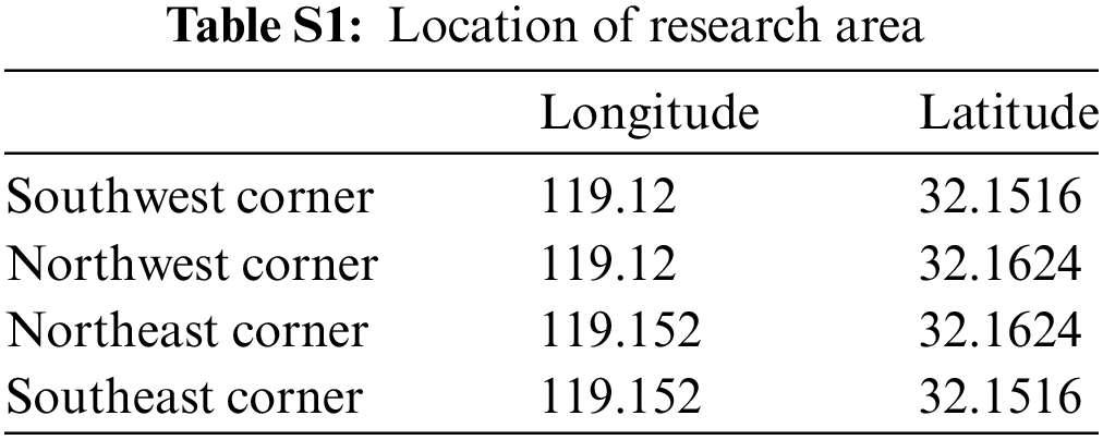
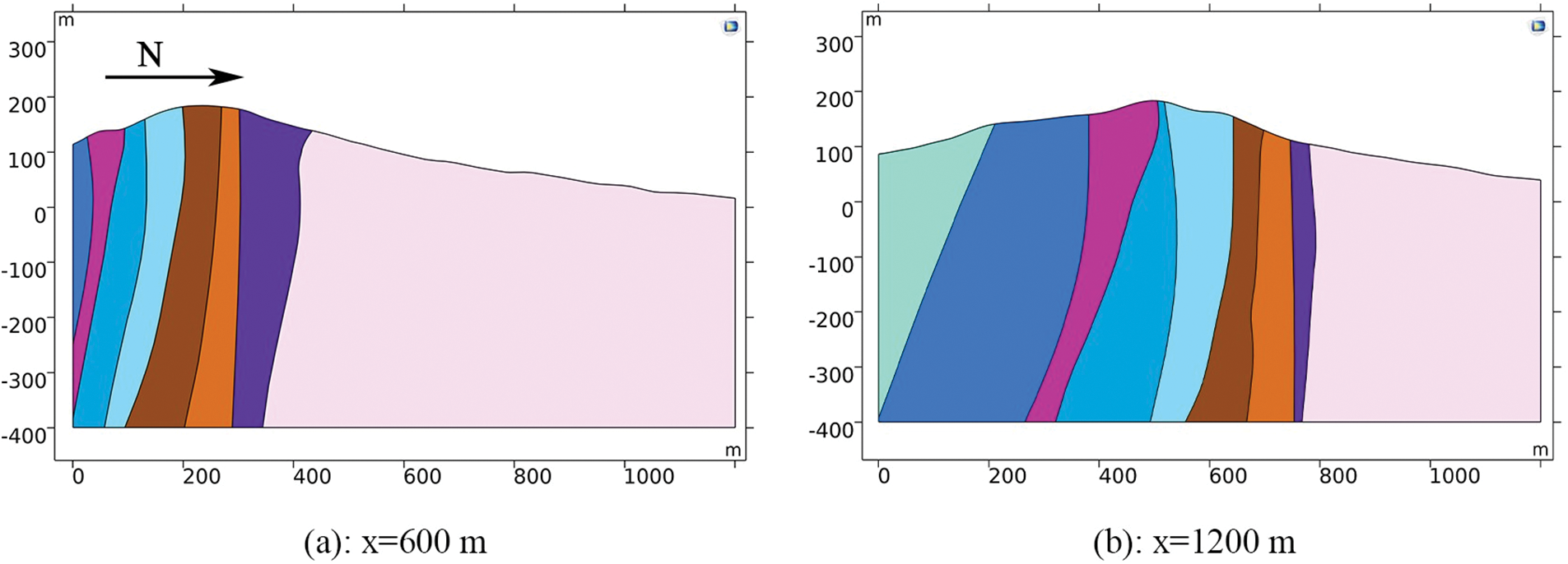
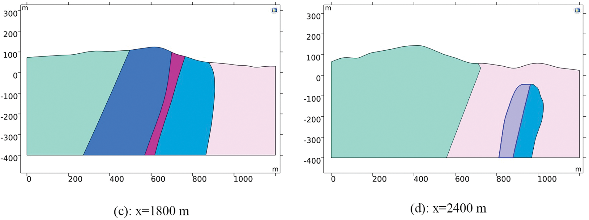
Figure S1: Profiles of the 3D geological model (YZ plane)
Figure S2: Distribution of element mass after mesh division of geological model
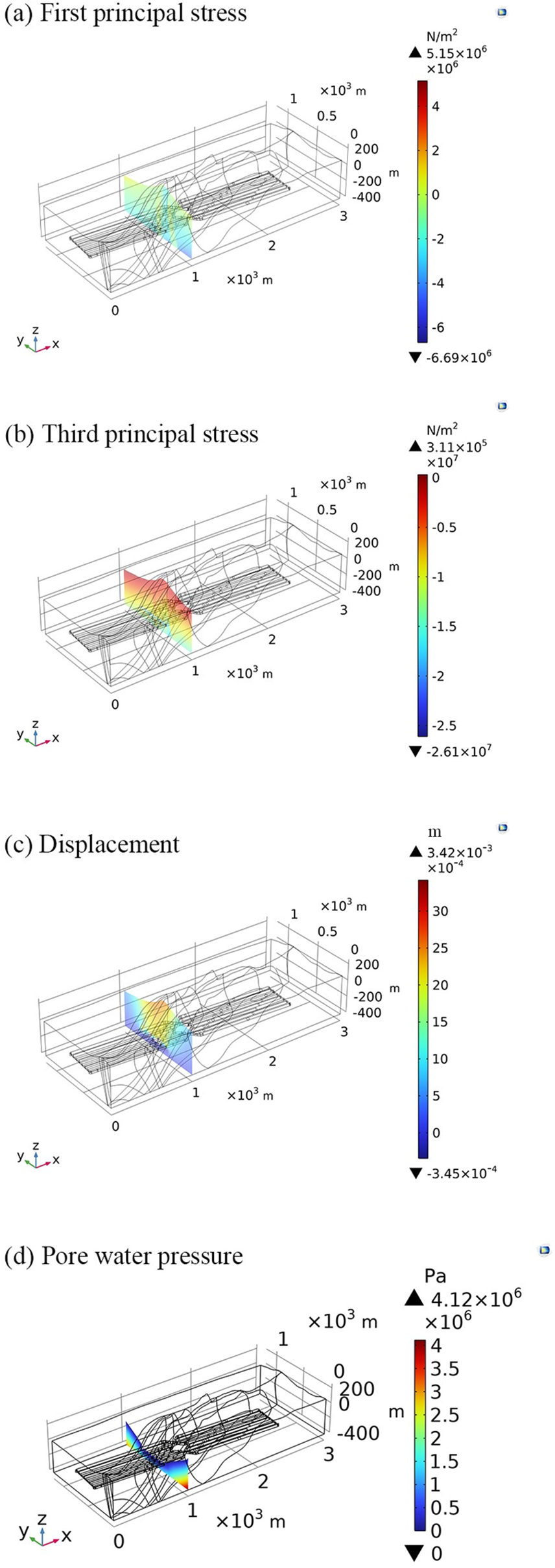
Figure S3: Simulation results at a typical section in the 3D model
Cite This Article
 Copyright © 2024 The Author(s). Published by Tech Science Press.
This work is licensed under a Creative Commons Attribution 4.0 International License , which permits unrestricted use, distribution, and reproduction in any medium, provided the original work is properly cited.
 Downloads
 Citation Tools