
 Submit a Paper
 Propose a Special lssue
 Open Access
ARTICLE

Sub-Homogeneous Peridynamic Model for Fracture and Failure Analysis of Roadway Surrounding Rock
1 School of Science, Qingdao University of Technology, Qingdao, 266520, China
2 College of Mechanics and Materials, Hohai University, Nanjing, 211100, China
3 Xibei Mining Co., Ltd., Shandong Energy Group, Xi’an, 710018, China
* Corresponding Author: Wei Xu. Email:
(This article belongs to the Special Issue: New Trends on Meshless Method and Numerical Analysis)
Computer Modeling in Engineering & Sciences 2024, 139(3), 3167-3187. https://doi.org/10.32604/cmes.2023.045015
Received 14 August 2023; Accepted 22 November 2023; Issue published 11 March 2024
 View Full Text
 Download PDF
Abstract
The surrounding rock of roadways exhibits intricate characteristics of discontinuity and heterogeneity. To address these complexities, this study employs non-local Peridynamics (PD) theory and reconstructs the kernel function to represent accurately the spatial decline of long-range force. Additionally, modifications to the traditional bond-based PD model are made. By considering the micro-structure of coal-rock materials within a uniform discrete model, heterogeneity characterized by bond random pre-breaking is introduced. This approach facilitates the proposal of a novel model capable of handling the random distribution characteristics of material heterogeneity, rendering the PD model suitable for analyzing the deformation and failure of heterogeneous layered coal-rock mass structures. The established numerical model and simulation method, termed the sub-homogeneous PD model, not only incorporates the support effect but also captures accurately the random heterogeneous micro-structure of roadway surrounding rock. The simulation results obtained using this model show good agreement with field measurements from the Fucun coal mine, effectively validating the model’s capability in accurately reproducing the deformation and failure mode of surrounding rock under bolt-supported (anchor cable). The proposed sub-homogeneous PD model presents a valuable and effective simulation tool for studying the deformation and failure of roadway surrounding rock in coal mines, offering new insights and potential advancements.Keywords
The surrounding rock of roadways is a composite, heterogeneous body comprising mineral particles and various defects formed through geological processes. It includes discontinuous structures such as fractures, joints, bedding, and faults [1]. These characteristics result in distinct mechanical properties, deformation, and failure behaviors compared to homogeneous materials. Under external loads and other disturbances, pre-existing micro-defects expand and aggregate, forming new macro-cracks and energy dissipation. Consequently, the strength and stiffness of the coal-rock mass are significantly reduced, ultimately leading to irreversible fracture failure, extensive roadway deformation, damage to support structures, and even overall roadway instability [2]. Over recent decades, advances in computing technology have made numerical methods an essential and valuable tool for investigating rock mechanical damage and failure. However, a key challenge in underground engineering is understanding the mechanical mechanisms behind the deformation and failure of surrounding rock in such scenarios and developing an effective numerical simulation approach capable of accurately capturing these processes.
In order to enhance understanding of roadway surrounding rock instability mechanisms, many researchers have conducted extensive research using numerical methods to investigate damage and failure characteristics. Traditional numerical techniques, such as the finite element method (FEM), require predicting crack location and propagation direction. When cracks propagate and branch, the mesh at the crack tip must be redefined, leading to pronounced mesh dependence in the simulation results. Introducing Goodman joint elements into the FEM framework allows describing discontinuous structures, such as joints and fissures within rock masses. However, numerical instability issues may arise when many joint elements are involved. To address these challenges, Belytschko et al. [3] proposed the extended finite element method (XFEM), introducing discontinuous and crack tip displacement field functions into the conventional finite element displacement mode. However, XFEM requires that cracks remain continuous at the interfaces of adjacent elements, which still makes it challenging to deal with complex failure problems like multiple crack interactions and branching. Another approach, the boundary element method (BEM) [4], treats discontinuous interfaces, such as cracks, as boundary interfaces. However, basic solutions for corresponding differential operators are not guaranteed, limiting their applicability. The discrete element method (DEM) [5] and other discrete medium numerical methods are widely used in geotechnical engineering. Nevertheless, their accuracy is relatively modest, the number of contact simulations is extensive, and numerous artificial assumptions must be introduced, potentially leading to significant discrepancies between simulation results and analytical situations. The numerical manifold method (NMM) [6] employs a finite element mesh as its mathematical coverage. During the process of crack propagation, this mathematical coverage remains unchanged. It is only necessary to place densely distributed nodes at the crack tip without regenerating the mesh. This approach can effectively simulate the progressive cracking process. However, the function corresponding to the control equations of NMM does not always exist, which limits its scope of application. The mesh-free method (MF) [7], utilizing node information and weight functions within compact support domains for local approximation, requires the addition of nodes near the crack tip to facilitate fracture simulation. Although MF methods eliminate the mesh dependency issue, they require the introduction of additional parameters. Moreover, their higher-order continuous approximation functions do not necessarily offer advantages when solving crack propagation problems, and accurately applying essential boundary conditions can be quite challenging.
From the perspective of the mechanism underlying material deformation and failure, coal-rock geotechnical materials comprise various micro-defects at the mesoscale, resulting in distinct mechanical behaviors for each mesoscale unit under external loads. The interaction among these mesoscale units within the coal-rock mass leads to an uneven internal stress distribution, producing nonlinear deformation characteristics at the macro-scale. Existing numerical modeling methods for heterogeneous geotechnical materials are complex in modeling and simulation, and traditional numerical methods face limitations in addressing discontinuous problems [8,9]. The primary challenge of traditional numerical methods in simulating fracture and related issues stems from discontinuities caused by cracks. Nevertheless, within the framework of continuum mechanics, various difficulties are inevitable. Peridynamics (PD) offers a multi-scale simulation approach capable of overcoming differential operation issues associated with singular or discontinuous nodes in continuum mechanics. PD has surmounted the limitations of spatial scale. Currently, the mechanical constitutive relationships of materials mostly rely on laboratory-scale specimen tests, which do not provide a unified constitutive model between the micro-scale and macro-scale. In contrast, PD utilizes a unified model to describe deformation and failure problems from the atomic scale to the macro-scale. This approach circumvents the complexities of traditional multi-scale mechanics methods for transferring mechanical quantities across different scales. It enables cross-scale numerical computations within a unified framework [10]. Other researchers, such as Zhou et al. [11,12], have integrated PD theory into the failure analysis of rock-like materials, examining crack growth under various loading conditions. Ma et al. [13] proposed an improved PD model to capture the stress-strain changes in rock materials and simulated the changes in cracking angles under different pre-crack angles and tensile load conditions. Moreover, Li et al. [14] used the PD method to simulate and study crack propagation and penetration in rock-like materials. Gao et al. [15] implemented a material node dormancy method based on PD to simulate roadway excavation, exploring the deformation and failure characteristics of surrounding rock during this process. Wang et al. [16–18] defined nonlocal stresses to obtain isotropic and deviatoric forces commensurate with deformations and proposed a new failure model to link computational PD with some phenomenological failure criteria, highly relevant for both brittle and quasi-brittle rocks. Furthermore, Fan et al. [19–21] conducted a hybrid PD-SPH (smoothed particle hydrodynamics) approach to simulate geotechnical materials fragmentation under buried explosive loads. However, the studies above on the failure of rock-like materials have not adequately considered material heterogeneity.
This study presents the construction of a quadratic constitutive force kernel function that effectively captures the spatial variation of long-range force. Departing from the micro-structural characteristics of coal-rock materials, this research addresses the heterogeneity of such materials and introduces a novel heterogeneous PD model centered on random pre-breaking “bonds.” The improved model treats the coal seams, roof, and floor layers as multi-layer composite materials. The incorporation of material heterogeneity is accomplished by establishing a pre-breaking “bond” coefficient, enabling the representation of the random heterogeneous mesostructure of surrounding rock in roadways and considering support effects. Subsequently, a corresponding numerical simulation method is developed to effectively analyze the deformation and failure of surrounding rock in extensive discontinuous and heterogeneous geotechnical engineering scenarios. The proposed sub-homogeneous PD model holds great potential in accurately analyzing complex geotechnical systems exhibiting significant discontinuities and material heterogeneity.
2.1 Bond-Based Peridynamic Model
As shown in Fig. 1, at a specific time
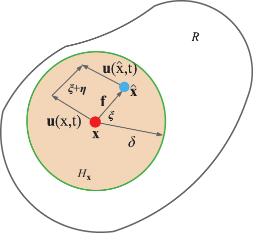
Figure 1: Schematic diagram of interaction between nodes in PD theory
In the space domain
The radius
When the distance between the material nodes
where
For homogeneous materials, the general expression of the constitutive force function
where
In addition to the relevant material parameters, the function
The scalar function
For the prototype micro elastic brittle (PMB) material model proposed by Silling et al. [22], the mechanical properties of the material are related to the micro-modulus
The potential energy
The deformation energy density of the material node
The coefficient indicates that the deformation energy density of each node occupies half of the deformation energy density of related two nodes.
Based on the PMB model, the pairwise force function of micro-elastic material is derivable from the scalar micro potential w,
where
In PD, local damage is represented by the ratio of the number of broken bonds to the total number of bonds in the horizon of each node,
2.2 Modification of Constitutive Force Function
In the constitutive function of the PMB model, the interaction between nodes changes in direct proportion to the elongation
For the modified model, the constitutive force function
The kernel function
The corresponding micro-modulus function
The relationship between micro-modulus function
For 2-D problems, the fracture energy
For plane stress problems,
Substituting Eq. (18) into (17), the approximate expression of the energy release rate
An approximate expression of the energy release rate
Then, the critical elongation
In the PD simulation system, the model is composed of material nodes. The motion of nodes obeys Newton’s second law. The mechanical response of the model can be obtained by solving the integral equation. Solving the motion equation of the PD simulation model involves time integration (difference scheme), spatial discretization, and integration. The unit volume force generated by the node
where
The numerical integration of time can be obtained by the Velocity-Verlet difference scheme. The displacement
where
The force boundary conditions in traditional theory cannot be directly applied in the PD model, and the external force usually needs to be applied through volume force density. The concentrated force and surface forces are applied on several layers of material nodes at the boundary. If the model is subject to the external force p, it can be converted into the external force density in PD.
3.1 PD Modeling of Heterogeneous Coal-Rock Mass
A substantial number of experiments in rock mechanics indicated that coal-rock geotechnical materials display significant variability in their physical and mechanical parameters, and these properties also demonstrate spatial heterogeneity. The heterogeneity in coal-rock mass materials arises from various factors. Characterizing this heterogeneity during numerical modeling is exceptionally challenging. Many researchers argue that heterogeneity due to micro-structural defects, such as pores and voids, is a crucial factor influencing the deformation and failure of coal-rock mass. Therefore, the geometric configuration and distribution of these micro-defects greatly influence the physical and mechanical properties of the materials.
Based on Eq. (13),
where
The material presents micro-defects, like pores and holes, leading to macro-level heterogeneity. In the context of the PD simulation, this heterogeneity appears through the absence of “bonds” between nodes, indicating local damage between them. This study introduces a random pre-breaking “bond” coefficient, symbolized by the initial damage quantity, into the uniform discrete simulation model to effectively characterize micro-defects, including material pores (as shown in Fig. 2), and thus capture the material’s heterogeneity. This method is inspired by the analysis of failure in functionally graded materials by Chen et al. [23].
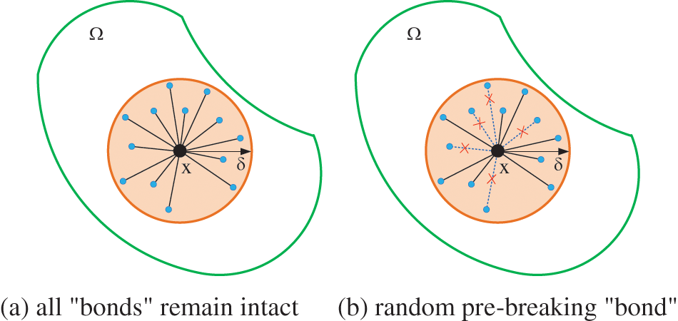
Figure 2: Schematic diagram of bond random breaking in heterogeneity PD model
Following this concept, this study defines the PD model’s heterogeneity as the simulation model’s initial damage amount. The process of setting the random pre-breaking “bond” is depicted in Fig. 3. The pre-breaking “bond” index of one node is,
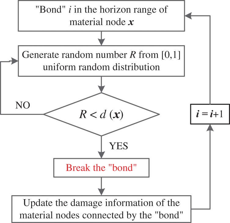
Figure 3: Flow chart of bond random pre-breaking
where
For the degree of heterogeneity of material nodes
For the uniform discrete model, assuming that the degree of heterogeneity in the model is consistent, i.e., the degree of heterogeneity of each node is
Then, the damage index
Compared to existing homogenized PD models, the model in this study can be referred to as a sub-homogeneous PD model. In the heterogeneous PD model, homogeneous dispersion is performed to ensure uniform physical and mechanical parameters for materials based on their heterogeneity degree. Establishing the sub-homogeneous PD model involves setting the heterogeneity degree coefficient, symbolized by the pre-breaking “bond”. Importantly, no additional pre-processing is necessary for the simulation model, and the model effectively reflects the random distribution characteristics of material heterogeneity. Moreover, the model’s implementation is straightforward, and the efficiency of heterogeneous modeling is unaffected by the simulation model’s size or the number of nodes, making it especially suitable for large discontinuous and heterogeneous geotechnical engineering applications.
Literature [24] indicated that coal-rock mass in deep strata undergoes compaction during diagenesis, typically resulting in low porosity. Regarding the coal-rock material heterogeneity in this study, Fig. 4 illustrates the material heterogeneity degree and the corresponding damage index represented by random pre-breaking “bonds.” It is important to note that the damage in the nephogram does not relate to damage caused by external loads on the model; instead, it represents the proportion of random pre-breaking “bonds,” quantifying the material heterogeneity degree. This serves as the initial condition of the model during the simulation process.
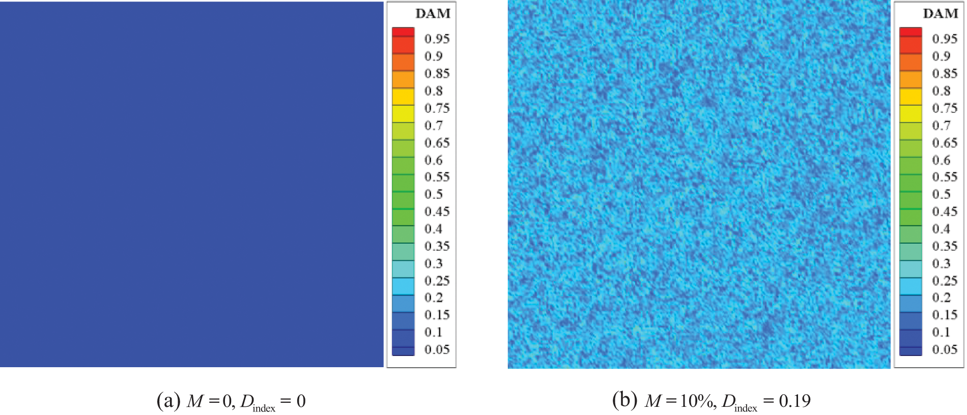
Figure 4: Degree of material heterogeneity and corresponding damage index characterized by bond random pre-breaking
3.2 Numerical Solution Process
Based on the modified PD model, this study develops a simulation program for the sub-homogeneous PD model using the FORTRAN language. The fundamental procedure is shown in Fig. 5. The pre-processing module involves compiling the model discrete program in MATLAB, enabling the acquisition of crucial information, such as node coordinates. Then, in the post-processing module, the simulation file information is read using Ensight, permitting the output of simulation results, including damage and displacement.
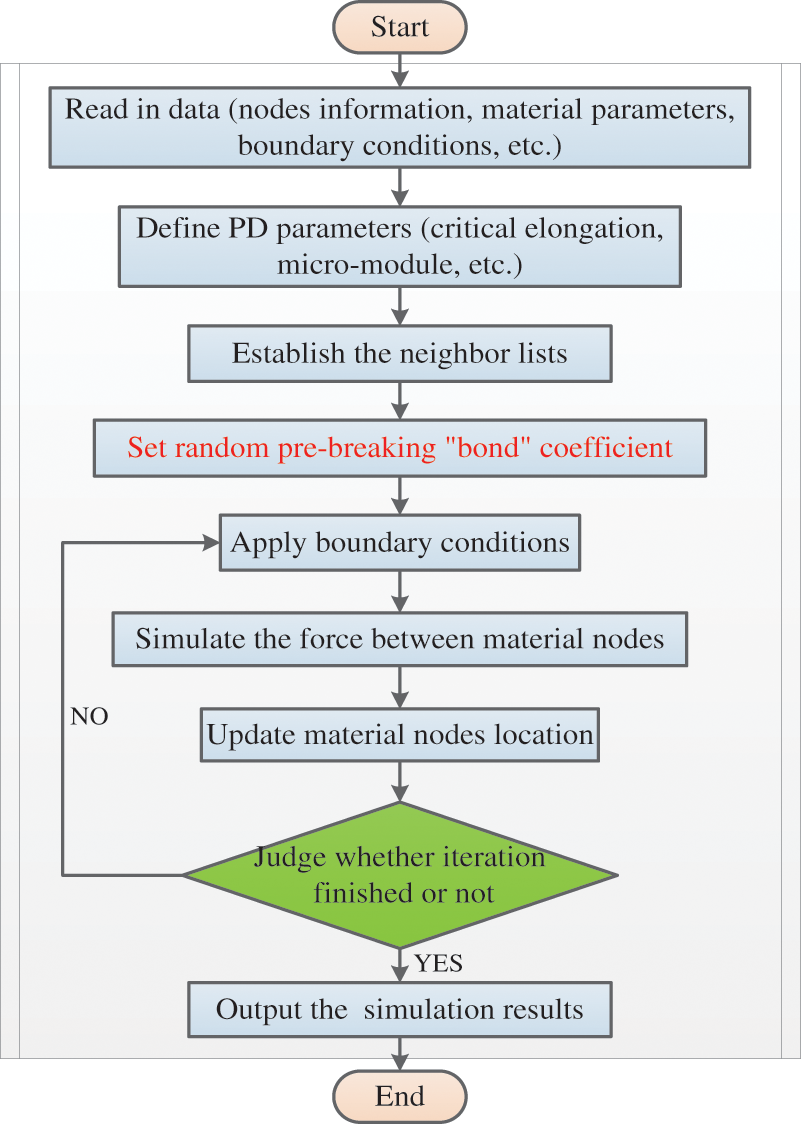
Figure 5: Flow chart of the sub-homogeneous PD model simulation program
4 Analysis of Surrounding Rock Excavation and Support of Roadway
This research focuses on the No. 3 upper 411 haulage roadway at Fucun Coal Mine as the research subject. The simulation model’s dimensions are set to 60 m × 40 m × 0.1 m (as illustrated in Fig. 6), using orthogonal uniform dispersion. The node lattice size, denoted as |Δx|, is set at 0.1 m, resulting in a total of 232320 nodes. Considering the heterogeneity degree, symbolized by the random pre-breaking “bond” coefficient, and to avoid premature damage at the model boundary, a suitably increased horizon range size was selected as δ = 6|Δx|.
Figure 6: PD simulation model of gob-side entry
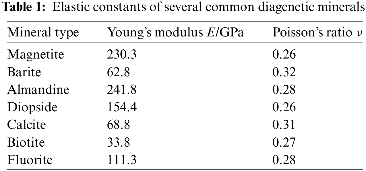
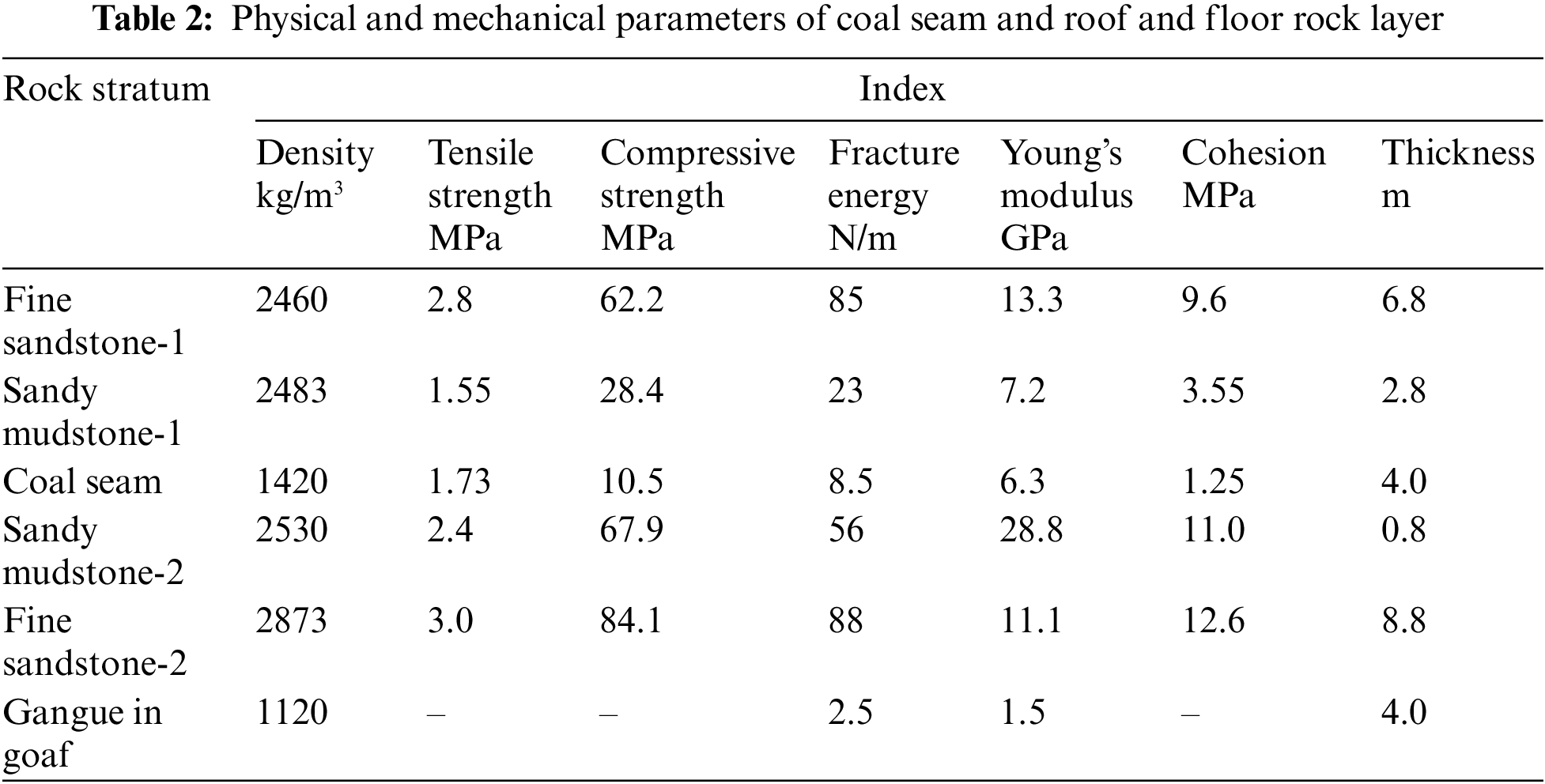
The Poisson’s ratio for diagenetic minerals is generally 0.2–0.3, as shown in Table 1, cited from the literature [25]. In bond-based PD, the Poisson’s ratio for plane stress problems is limited to 1/3, and for plane strain problems, to 1/4. Thus, the influence of Poisson’s ratio on simulation results is not significant. The problem is then simplified as a plane strain problem, with a Poisson’s ratio of ν = 0.25 assigned. The physical and mechanical parameters of the material are outlined in Table 2. The haulage roadway, situated along the goaf, is approximately buried at a depth of −500 m. For most crystalline rock masses, the porosity is relatively small, often ranging from 0.1% to 10%. The surrounding rock stratum shows a relatively dense composition with low porosity, resulting in a material heterogeneity of 5% selected for this study.
In this proposed model, the PD parameters of various interlayer materials are different, and the micro-modulus function
The composite “bond” micro-modulus function
The macro strength and other mechanical parameters of materials with different degrees of heterogeneity are also different. Chen et al. [26], based on the wave propagation theory under the plane stress state, obtained the relationship between longitudinal wave velocity and elastic modulus of heterogeneous materials through a large number of numerical tests.
where
The corresponding Young’s modulus values of materials under different degrees of heterogeneity can be obtained through Eq. (34), and the following relationship exists between the Young’s modulus
where
Substitute Eq. (35) into Eq. (30) to get,
Similarly, the fracture energy
where
4.2 Consideration of Support Structure
The reinforcement effect of the bolt on the surrounding rock of the roadway is shown in Fig. 7. Generally, the tensile strength
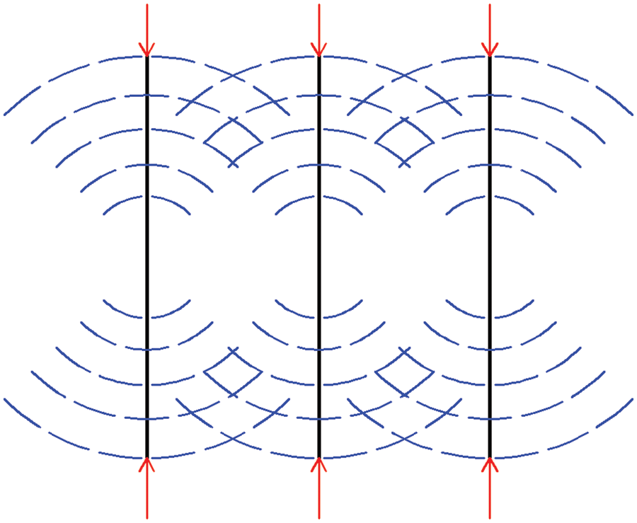
Figure 7: Schematic diagram of bolt reinforcement
where A is the surface area of the roadway; r is the radius of the bolt (cable) body.
Generally, inclined bolts will be applied at the shoulder angle of the roadway, so Eq. (38) can be rewritten as,
where
The tensile strength
In PD theory, whether the “bond” cut off is judged by the relationship between the elongation of the “bond” and the critical elongation between nodes. If the critical elongation
In the simulation process, the local damage of nodes can be obtained from Eq. (13).
The numerical simulation process for roadway excavation and support application encompasses three primary steps: (1) establishing self-weight stress balance in the model, (2) executing roadway excavation, and (3) applying support. The study employs the gravity field method to create the initial stress field balance within the simulation model. The model’s bottom vertical displacement is fixed, and the normal horizontal displacement of its sides is also fixed. A balanced state is attained by allowing the model to achieve equilibrium solely through self-weight. Displacement monitoring nodes are strategically positioned symmetrically along the model’s horizontal axis. Once the displacement at these nodes stabilizes, the model has attained its initial balance. Fig. 8 shows the vertical displacement at selected monitoring points, revealing that the model reaches equilibrium after 15,000 simulation iterations. After equilibrium, the force density of all nodes in the model is extracted, using these values as the initial force densities for the nodes in the roadway excavation simulation. The node displacements generated during the initial stress field equilibrium are reset to zero, ensuring precise simulations in subsequent excavation and support application phases.
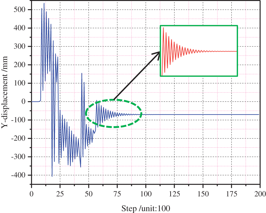
Figure 8: Vertical displacement curve of monitoring node during loading
4.4 Simulation Results and Analysis
The PD parameters, such as the micro-modulus function and critical elongation of nodes in the anchor bolt (cable) area, are determined using Eqs. (40) and (41). Figs. 9 and 10 depict the initial roadway support scheme’s cross-section and plan view. The roof support comprises Φ18/Q500 left-handed bolts without longitudinal reinforcement, each 2.4 m long, and Φ17.8 × 6000 mm anchor cables. The two side supports consist of similar bolts, each 2.0 m long. However, this scheme severely damages the coal seam on both roadway sides. In order to improve support effectiveness, the spacing between side anchor bolts is reduced based on the original scheme, while the spacing between roof anchor bolts (cables) remains constant, as shown in Fig. 11. The row spacing of anchor bolts (cables) remains as in the original scheme.
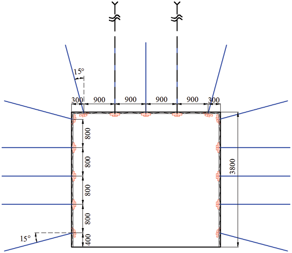
Figure 9: Cross section of original roadway support (unit: mm)
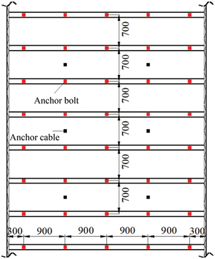
Figure 10: Scheme of original roadway support (unit: mm)
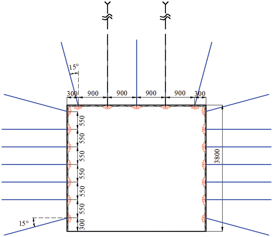
Figure 11: Cross section of modified roadway support (unit: mm)
Unlike traditional continuum mechanics methods, bond-based PD eschews stress and strain descriptions. The study’s analysis focuses on horizontal displacement changes of the roadway’s sides and the roof’s vertical displacement variations. Figs. 12 and 13 show these displacements under the original support scheme: the coal side’s maximum deformation is 35 mm, and the coal pillar side is 59 mm, totaling a maximum deformation of 94 mm. The maximum vertical displacement of the roadway roof is 53 mm.
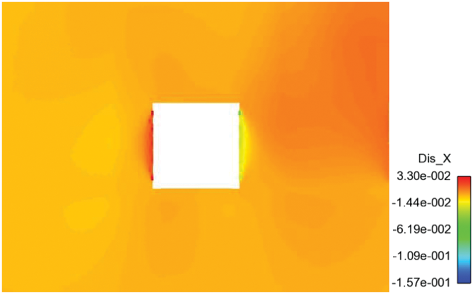
Figure 12: Horizontal displacement of roadway surrounding rock under original support scheme (unit: m)
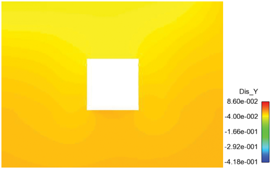
Figure 13: Vertical displacement of roadway surrounding rock under original support scheme (unit: m)
Figs. 14 and 15 illustrate the displacements under the enhanced support scheme. The maximum deformation of the coal side is 26 mm, and that of the coal pillar side is 42 mm, leading to a total maximum deformation of 68 mm. The maximum vertical displacement of the roadway roof is 51 mm.
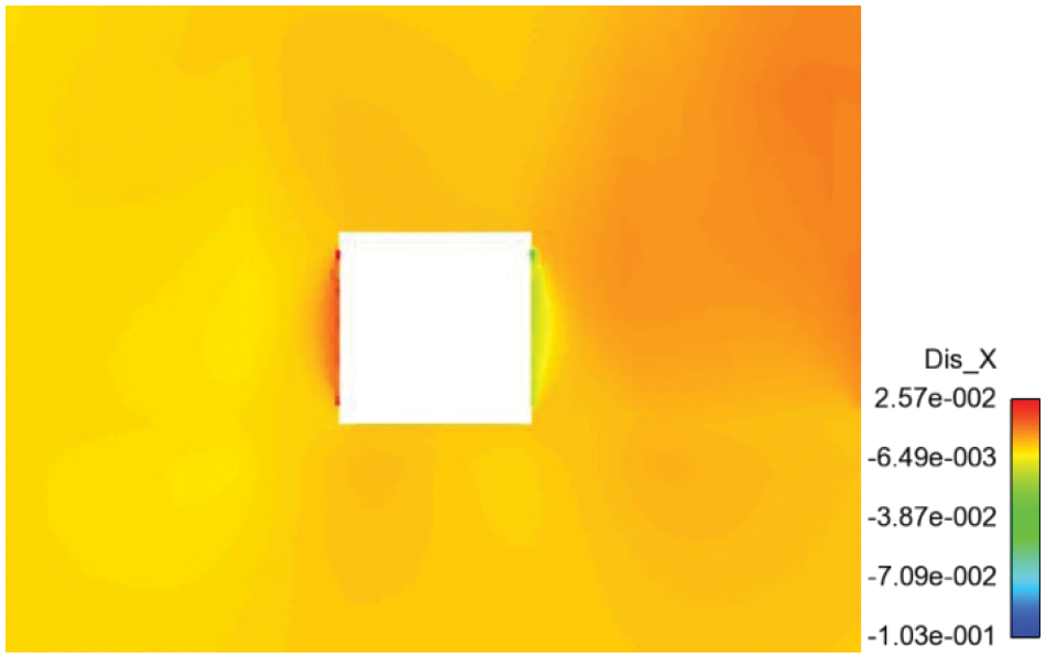
Figure 14: Horizontal displacement of roadway surrounding rock under modified support scheme (unit: m)
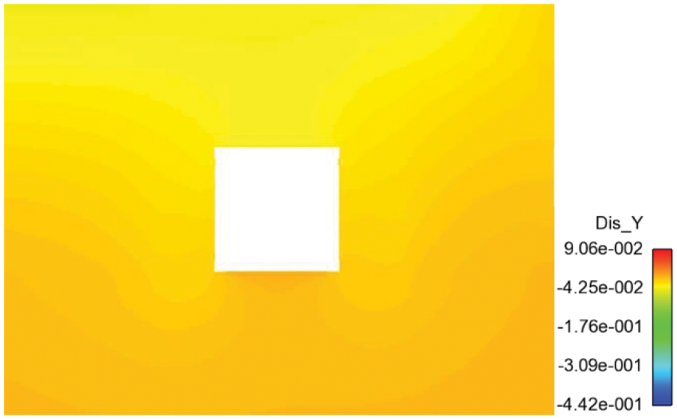
Figure 15: Vertical displacement of roadway surrounding rock under modified support scheme (unit: m)
Accordingly, reducing the spacing between side bolts and increasing support density significantly mitigates the horizontal movement of the roadway sides. The enhanced support scheme effectively controls roadway deformation during its service period. Fig. 16 visually demonstrates the enhanced scheme’s actual support effect.
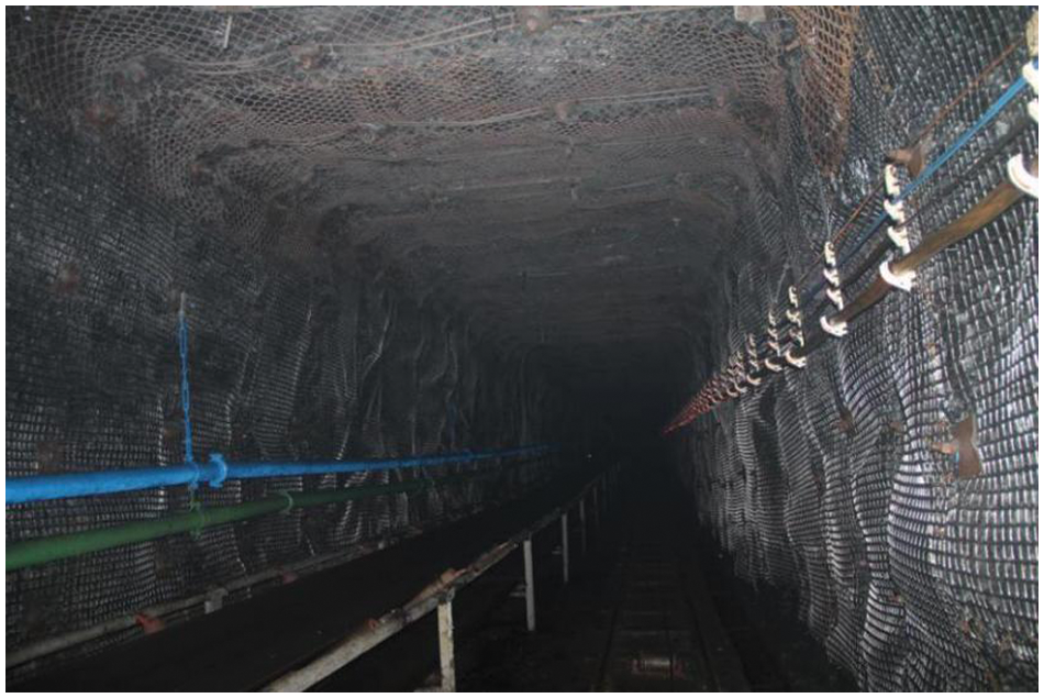
Figure 16: Actual effect of roadway support
In order to assess the support scheme’s feasibility, monitoring the ground pressure on the support system and surrounding rock is imperative. Observing mine pressure in the stopping roadway involves various instruments to measure macroscopic ground pressure manifestations, such as displacements of the roof, floor, and sides and deformation of the coal seam and support structure. The observation sections’ layout appears in Fig. 17.
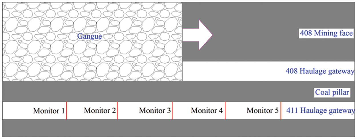
Figure 17: Layout of observation sections
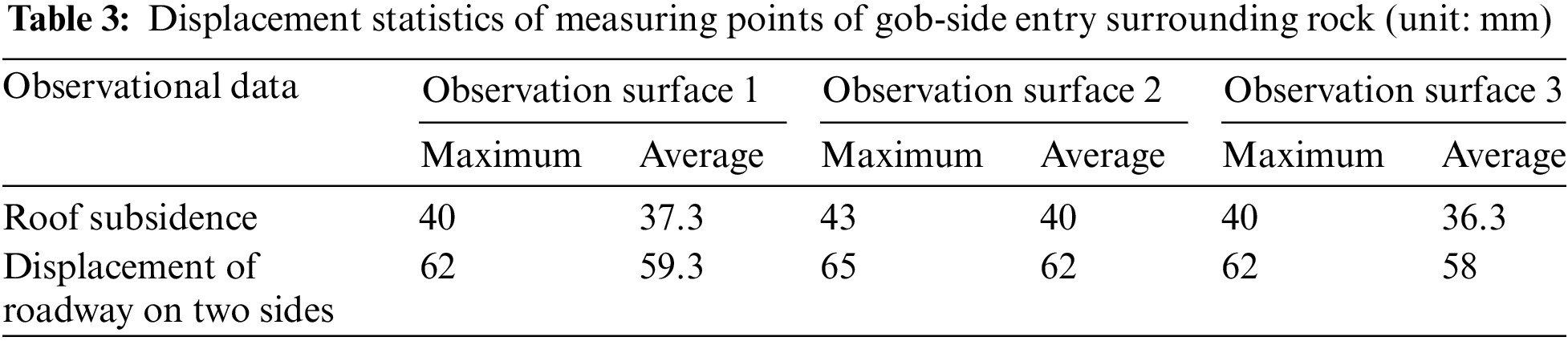
Table 3 presents statistical data on deformations observed in the roof and sides of the roadway in field observations. The results show a maximum deformation of 65 mm on the sides and a roof subsidence of 43 mm. Remarkably, the simulated deformation of the surrounding rock by the sub-homogeneous PD model closely aligns with field measurements, meeting the engineering requirements for investigating the deformation and failure characteristics of the surrounding rock and optimizing the support scheme.
This study simulates the fracture and failure process of roadway surrounding rock subjected to support application using an improved sub-homogeneous PD model. This investigation analyzes the impact of various factors, including kernel function, heterogeneity, and support application, on the fracture pattern and failure mode.
(1) A quadratic constitutive force kernel function was developed to account for the spatial variation of long-range forces. Moreover, considering the heterogeneity of coal-rock mass materials and structures, a random pre-breaking “bond” coefficient was introduced, characterizing the degree of heterogeneity in rock-like materials. Establishing this heterogeneous PD model, based on uniform dispersion and reflecting the random distribution characteristics of material heterogeneity, enabled the simulation of deformation and failure in heterogeneous materials and structures.
(2) Given the layered composition of coal seams, including its roof and floor layers, a PD model was developed for layered coal-rock mass structures. To address underground engineering challenges, this bond-based PD model adopted a method of initial balance. Additionally, a support facility application mode for the PD model was proposed, facilitating the analysis of underground engineering. The proposed PD model effectively captured the random heterogeneous meso-structure of the roadway surrounding rock while considering the influence of support measures.
(3) The PD method was employed to assess coal-rock masses’ structural deformation and failure. By employing the sub-homogeneous PD model, the study explored the deformation and failure characteristics of roadway surrounding rock when supported by bolts (cables). The displacement distribution along both sides and the roof of the roadway was meticulously analyzed. A comparative assessment between the simulation outcomes and actual measurements revealed a high degree of consistency, confirming the sub-homogeneous PD model’s efficacy in replicating the discontinuous deformation and failure of diverse coal-rock mass structures.
Acknowledgement: The authors would like to acknowledge the Key Laboratory of Geotechnical Mechanics and Offshore Underground Engineering of Qingdao for promoting this research and providing the laboratory facility and support, the National Natural Science Foundation of China and the Natural Science Foundation of Shandong Province for the financial support. The authors thank Shandong Energy Group for providing observation data for this project.
Funding Statement: The research described in this paper was financially supported by the National Natural Science Foundation of China (Nos. 12302264, 52104004, 12072170, and 12202225), the Natural Science Foundation of Shandong Province (No. ZR2021QA042) and Special Fund for Taishan Scholar Project (No. Tsqn202211180).
Author Contributions: The authors confirm contribution to the paper as follows: study conception and design: Shijun Zhao, Qing Zhang; data collection: Weizhao Zhang; analysis and interpretation of results: Yusong Miao, Xinbo Zhao; draft manuscript preparation: Shijun Zhao, Wei Xu. All authors reviewed the results and approved the final version of the manuscript.
Availability of Data and Materials: The datasets used or analyzed during the current study are available from the corresponding author upon reasonable request.
Conflicts of Interest: The authors declare that they have no conflicts of interest to report regarding the present study.
References
1. Yang, D., He, X. Q., Yi, S. H., Liu, X. F. (2019). An improved ordinary state-based peridynamic model for cohesive crack growth in quasi-brittle materials. International Journal of Mechanical Sciences, 153–154, 402–415. [Google Scholar]
2. Pan, P. Z., Feng, X. T., Hudson, J. A. (2012). The influence of the intermediate principal stress on rock failure behavior: A numerical study. Engineering Geology, 124(1), 109–118. [Google Scholar]
3. Belytschko, T., Black, T. (1999). Elastic crack growth in finite elements with minimal remeshing. International Journal for Numerical Methods in Engineering, 45(5), 601–620. [Google Scholar]
4. Sun, J., Liu, Y. H., Yao, Z. H., Zheng, X. P. (2022). A data-driven multi-flaw detection strategy based on deep learning and boundary element method. Computational Mechanics, 71, 517–542. [Google Scholar]
5. Zhu, Y., Liu, C., Liu, H., Kou, Y. D., Shi, B. (2023). A multi-field and fluid-solid coupling method for porous media based on DEM-PNM. Computers and Geotechnics, 154, 105118. [Google Scholar]
6. Shi, G. H. (1997). Numerical manifold method and discontinuous deformation analysis. Beijing, China: Tsinghua University Press. [Google Scholar]
7. Li, S. F., Liu, W. K. (2002). Meshfree particle methods and their applications. ASME Applied Mechanics Review, 55, 1–34. [Google Scholar]
8. Liu, G., Ma, F. S., Zhao, H. J., Feng, X. T., Guo, J. (2018). Failure mechanisms study of heterogeneous jointed rock mass considering statistical damage model in tensile-shear test. Rock and Soil Mechanics, 39(s1), 9–20. [Google Scholar]
9. Cheng, Z. L., Sui, W. B., Ning, Z. F., Gao, Y. F., Hou, Y. N. et al. (2018). Microstructure characteristics and its effects on mechanical properties of digital core. Chinese Journal of Rock Mechanics and Engineering, 37(2), 449–460. [Google Scholar]
10. Stenstrom, C., Eriksson, K., Bobaru, F., Golling, S., Jonsen, P. (2023). The essential work of fracture in peridynamics. International Journal of Fracture, 242, 129–152. [Google Scholar]
11. Zhou, X. P., Shou, Y. D. (2016). Numerical simulation of failure of rock-like material subjected to compressive loads using improved peridynamic method. International Journal of Geomechanics, 17(3), 1–12. [Google Scholar]
12. Wang, Y. T., Zhou, X. P., Wang, Y., Shou, Y. D. (2018). A 3-D conjugated bond-pair-based peridynamic formulation for initiation and propagation of cracks in brittle solids. International Journal of Solids and Structures, 134, 89–115. [Google Scholar]
13. Ma, P. F., Li, S. C., Yuan, C., Zhou, H. Y., Wang, M. L. et al. (2021). Simulations of crack propagation in rock-like materials by peridynamics based on SED criterion. Chinese Journal of Geotechnical Engineering, 43(6), 1109–1117. [Google Scholar]
14. Li, W. J., Zhu, Q. Z., Ni, T. (2020). A local strain-based implementation strategy for the extended peridynamic model with bond rotation. Computer Methods in Applied Mechanics and Engineering, 358, 112625. [Google Scholar]
15. Gao, C. L., Zhou, Z. Q., Li, Z. H., Li, L. P., Cheng, S. (2020). Peridynamics simulation of surrounding rock damage characteristics during tunnel excavation. Tunnelling and Underground Space Technology, 97, 103289. [Google Scholar]
16. Wang, Y. T., Zhou, X. P., Kou, M. M. (2019). Three-dimensional numerical study on the failure characteristics of intermittent fissures under compressive-shear loads. Acta Geotechnica, 14, 1161–1193. [Google Scholar]
17. Zhou, X. P., Wang, Y. T. (2021). State-of-the-art review on the progressive failure characteristics of geomaterials in peridynamic theory. Journal of Engineering Mechanics, 147(1), 03120001. [Google Scholar]
18. Wang, Y. T., Wu, W. (2023). A bond-level energy-based peridynamics for mixed-mode fracture in rocks. Computer Methods in Applied Mechanics and Engineering, 414, 116169. [Google Scholar]
19. Fan, H. F., Bergel, G. L., Li, S. F. (2015). A hybrid peridynamics-SPH simulation of soil fragmentation by blast loads of buried explosive. International Journal of Impact Engineering, 87, 14–27. [Google Scholar]
20. Fan, H. F., Li, S. F. (2017). A peridynamics-SPH modeling and simulation of blast fragmentation of soil under buried explosive loads. Computer Methods in Applied Mechanics and Engineering, 318, 349–381. [Google Scholar]
21. Ren, B., Fan, H. F., Bergel, G. L., Regueiro, R. A., Lai, X. et al. (2014). A peridynamics-SPH coupling approach to simulate soil fragmentation induced by shock waves. Computational Mechanics, 55, 287–302. [Google Scholar]
22. Silling, S. A., Askari, E. (2005). A meshfree method based on the peridynamic model of solid mechanics. Computers and Structures, 83, 1526–1535. [Google Scholar]
23. Chen, Z. G., Sina, N., Zhang, G. F., Bobaru, F. (2018). Peridynamic functionally graded and porous materials: Modeling fracture and damage. In: Voyiadjis, G. Z. (Ed.Handbook of nonlocal continuum mechanics for materials and structures. Switzerland: Springer International Publishing. [Google Scholar]
24. Feng, Z. C., Zhao, Y. S., Wen, Z. M. (2005). Percolation mechanism of fractured coal rocks as dual-continua. Chinese Journal of Rock Mechanics and Engineering, 24(2), 236–240. [Google Scholar]
25. Chen, Y., Huang, T. F. (2001). Rock physics. Beijing, China: Peking University Press. [Google Scholar]
26. Chen, Z. G., Sina, N., Bobaru, F. (2019). A peridynamic model for brittle damage and fracture in porous materials. International Journal of Rock Mechanics and Mining Sciences, 122, 104059. [Google Scholar]
Cite This Article
 Copyright © 2024 The Author(s). Published by Tech Science Press.
This work is licensed under a Creative Commons Attribution 4.0 International License , which permits unrestricted use, distribution, and reproduction in any medium, provided the original work is properly cited.
 Downloads
 Citation Tools