
 Submit a Paper
 Propose a Special lssue
 Open Access
ARTICLE

Blade Wrap Angle Impact on Centrifugal Pump Performance: Entropy Generation and Fluid-Structure Interaction Analysis
1 School of Mechanical Engineering, Universiti Sains Malaysia, Engineering Campus, Nibong Tebal, Penang, 14300, Malaysia
2 Chemical Engineering Department, Faculty of Engineering, Al-Muthanna University, Muthanna, 66001, Iraq
3 Faculty of Mechanical Engineering & Technology, Universiti Malaysia Perlis (UniMAP), Arau, Perlis, 02600, Malaysia
* Corresponding Author: Mohd Sharizal Abdul Aziz. Email:
Computer Modeling in Engineering & Sciences 2024, 140(1), 109-137. https://doi.org/10.32604/cmes.2024.047245
Received 31 October 2023; Accepted 02 January 2024; Issue published 16 April 2024
 View Full Text
 Download PDF
Abstract
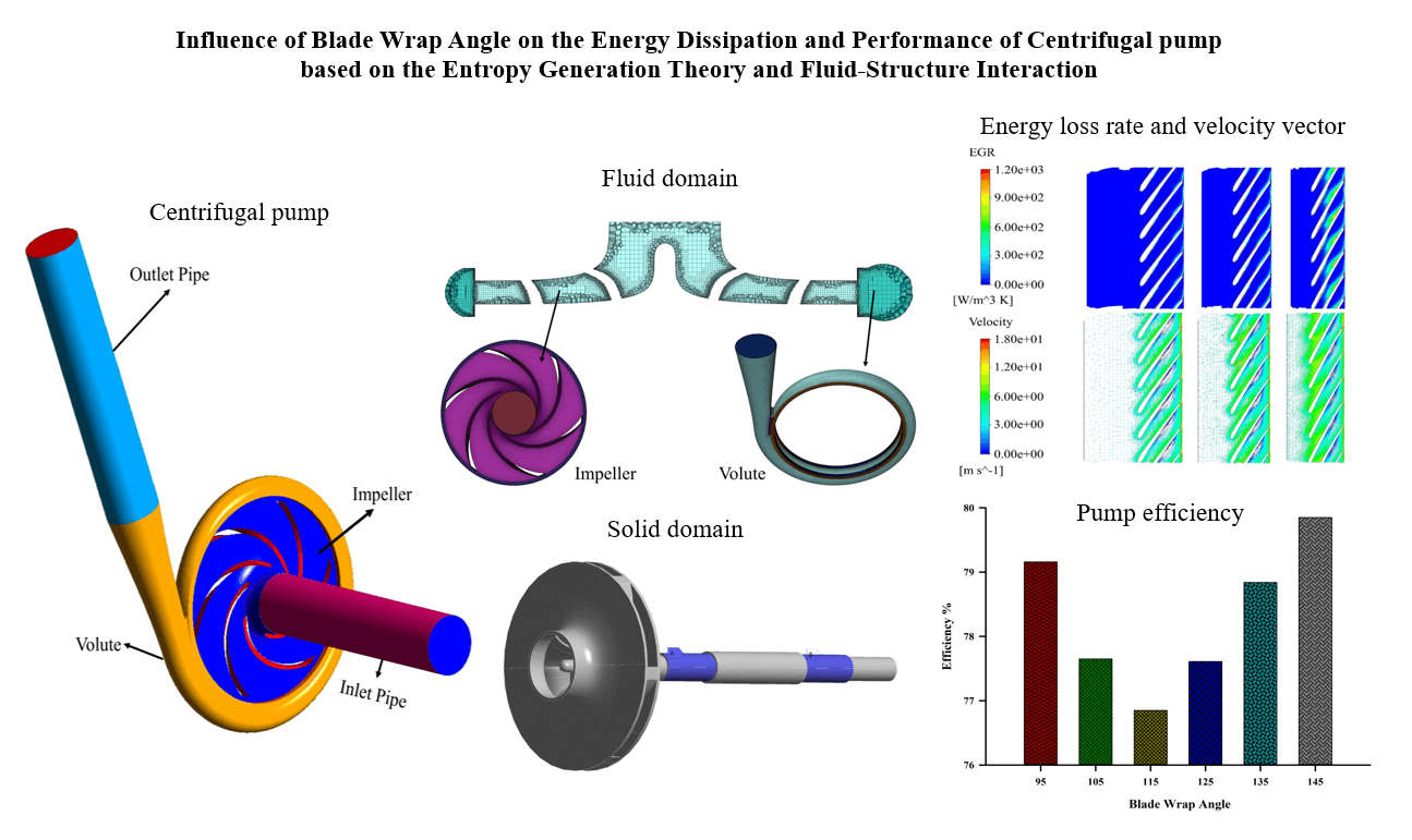
The centrifugal pump is a prevalent power equipment widely used in different engineering patterns, and the impeller blade wrap angle significantly impacts its performance. A numerical investigation was conducted to analyze the influence of the blade wrap angle on flow characteristics and energy distribution of a centrifugal pump evaluated as a low specific speed with a value of 69. This study investigates six impeller models that possess varying blade wrap angles (95°, 105°, 115°, 125°, 135°, and 145°) that were created while maintaining the same volute and other geometrical characteristics. The investigation of energy loss was conducted to evaluate the values of total and entropy generation rates (TEG, EGR). The fluid-structure interaction was considered numerically using the software tools ANSYS Fluent and ANSYS Workbench. The elastic structural dynamic equation was used to estimate the structural response, while the shear stress transport k – ω turbulence model was utilized for the fluid domain modeling. The findings suggest that the blade wrap angle has a significant influence on the efficiency of the pump. The impeller featuring a blade wrap angle of 145° exhibits higher efficiency, with a notable increase of 3.76% relative to the original model. Variations in the blade wrap angle impact the energy loss, shaft power, and pump head. The model with a 145° angle exhibited a maximum equivalent stress of 14.8 MPa and a total deformation of 0.084 mm. The results provide valuable insights into the intricate flow mechanism of the centrifugal pump, particularly when considering various blade wrap angles.Graphic Abstract
Keywords
Nomenclature
| b2 | Impeller outlet width (mm) |
| b3 | Volute inlet width (mm) |
| D1 | Impeller inlet diameter (mm) |
| D2 | Impeller outlet diameter (mm) |
| D3 | Volute inlet diameter (mm) |
| D4 | Volute outlet diameter (mm) |
| E | Modulus of elasticity (Pa) |
| Blade passing frequency (Hz) | |
| H | Head (m) |
| n | Rotating speed (r/min) |
| ns | Specific speed |
| Psh | Shaft power (W) |
| Q | Flow rate (m3/h) |
| Entropy generation rate (W/m3. k) | |
| Entropy generation resulting based on viscous dissipation (W/m3. k) | |
| Entropy generation resulting based on turbulent dissipation (W/m3. k) | |
| u2 | Circumferential velocity of the impeller outlet (m/s) |
| y+ | Dimensionless wall distance |
| Z | Blade number |
| Greek Symbols | |
| β2 | Blade outlet angle (°) |
| γ | Poisson’s ratio |
| θ | Angle of volute tongue (°) |
| ρm | Density of the pump material (kg/m3) |
| σs | Tensile yield strength (MPa) |
| σb | Tensile ultimate strength (MPa) |
| ϕ | Wrap angle (°) |
| ψ | Head coefficient |
Centrifugal pumps have widespread usage in a variety of technological fields because of their cheap cost, remarkable efficiency, and steady flow rate, as well as their simplicity in construction and minimal maintenance requirements. The impeller is a crucial conduit for fluid behavior inside the flow channel, exerting a substantial influence on the movement of the fluid. The system’s performance is intrinsically linked to the rotating component since it represents the only element in motion [1]. Furthermore, the profile of the impeller blade plays a pivotal role in dictating the flow characteristics of the fluid [2], hence exerting a direct influence on the operational efficiency of pumps and other turbomachinery devices. The wrap angle of the impeller blade is an essential structural element that plays a critical role in the hydraulic design of centrifugal pumps. It refers to the geometric angle created by the tangent lines intersecting a blade’s leading and trailing edges. Elevating the wrap angles would yield a more elongated flow channel amidst the blades, causing a notable escalation in frictional dissipation. A narrow blade angle will provide a short flow channel. However, it will also result in poor control over the flow inside the impeller, which will probably cause separation loss. Hence, the blade wrap angle is essential in determining blade shape, flow pattern inside the impeller, and the overall performance of the pump [3].
Several investigations have been conducted to analyze the wrap angle’s impact on the pump’s hydraulic efficiency. Tan et al. [3] investigated the effect of wrap angle on the operational performance of centrifugal pumps. The obtained findings prove that an increase in the wrap angle positively impacts flow characteristics. Tan et al. [4] examined the influence of three different impeller types, with varying wrap angles, on the flow characteristics of a pump with a single channel. The results indicate a positive relationship between the wrap angle, pump head, and efficiency. As the wrap angle increased, there was a progressive increase in both the pump head and efficiency. Yang et al. [5] investigated the effects of impeller trimming on the pump as turbine (PAT) performance. The study revealed a reduced impeller trimming and increased flow discharge when the PAT reached the best efficiency point (BEP). Tan et al. [6] investigated the impact of blade wrap angle on the operational efficiency of a centrifugal pump with a single blade. They have examined five distinct levels of wrapping, and they found that increasing the blade wrap angle leads to a proportional rise in the pump head and efficiency. Nevertheless, it leads to reduced radial force during part-loading conditions. The investigation carried out by Gao et al. [7] intended to examine the influence of blade wrap angle on the flow characteristics and hydraulic losses of an open-design vortex pump. The researchers concluded that a reduction in blade wrap angle is associated with increased hydraulic loss. However, this reduction also improves the pump’s efficiency and the head of the vortex pump. Moreover, Liang et al. [8] investigated the implications of blade wrap angle on the flow parameters and acoustic behavior. The researchers have determined that the blade wrap angle has little effect on the pump’s performance characteristics; however, it substantially influences the pressure distribution. The reduction in the angle reduced pressure fluctuation in the volute tongue area, leading to a decrease in the magnitude of the pressure fluctuation at the Blade Passing Frequency (BPF). In their work, Hao et al. [9] examined the functionality of a single-channel pump. They employed a numerical model to analyze the influence of the blade wrap angle on the pump’s performance. The results suggest that increasing the blade wrap angle has a beneficial effect on improving the performance, efficiency, and power output. The augmentation of the wrapping angle results in a reduction of pressure pulsations within the flow channel. Du et al. [10] investigated four PAT models with varying blade wrap angles. The researchers discovered that the wrap angle affects PAT performance and significantly impacts the pump’s best efficiency points (BEPs). The variation of the blade wrap angles improves performance from 12.9% to 16.0%. The reduction in blade wrap angle could mitigate hydraulic losses in the impeller, decreasing the overall water head reduction. The experimental results of Wang et al. [11] indicated an optimum angle for maximum efficiency under design conditions. The vibration intensity and noise did not experience a substantial impact by the modification of the blade wrap angle. Bai et al. [12] found that the wrap angle could improve the fluid behavior of the hydraulic turbine. The enhancement of the blade wrap angle could improve impeller flow and lead to an increase in maximum efficiency. However, investigating the effect of different blade wrap angles on the magnitude and location of energy loss and structural behavior in a pump has received limited research attention.
This study aims to investigate varied degrees of blade wrap angle to analyze the impact of its modification on the fluid characteristics and structural behavior of a centrifugal pump. First, simulation results are validated with the experimental data. Then, the pressure distribution, energy loss, and structural behavior are analyzed. This study employs entropy generation techniques and the two-way fluid-structure interaction (FSI) method to investigate the impeller strength at various degrees of blade wrap angles. The findings of this study are valuable in terms of serving as a point of reference for impeller design and enhancing our understanding of the influence of wrap angles on centrifugal pump efficiency.
2 3D Physical Model and Numerical Analysis
2.1 Main Parameters of Fluid and Solid Domains
A low-specific speed of (69) centrifugal pump, which was employed by Zhang et al. [13,14] in their previous projects, has been considered in this work. Table 1 presents the fundamental characteristics of the pump model used in the study. Six impellers with different wrap angles (95°, 105°, 115°, 125°, 135°, and 145°) were considered, while the other parameters remained unchanged. The three-dimensional fluid domain has been created using the CFturbo V2020 software 1.1 obtained from the primary design (see Fig. 1). Inlet and outlet pipes have been installed with a length of five times the pump’s suction to provide an unreversed fully developed flow and prevent an unstable flow [15–17]. Three of the monitoring points have been chosen at the volute in the region close to the impeller, which is the area more affected by the rotor-stator interaction, and one point was pointed at the volute outlet to monitor the pressure outlet at the volute. Fig. 2 depicts the monitoring points in the pump case.
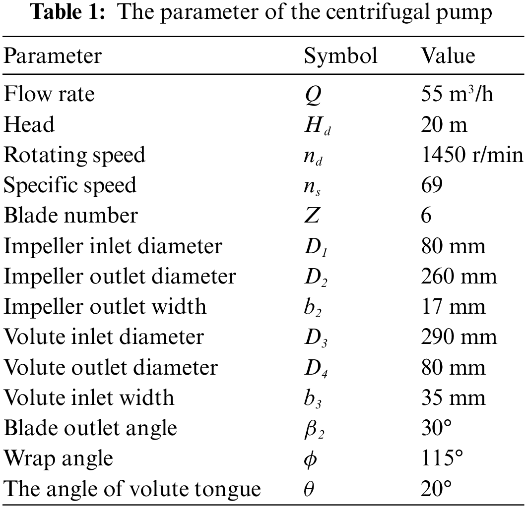

Figure 1: The three-dimensional model and boundary conditions of the centrifugal pump

Figure 2: The location of the monitoring point used in the simulation on the volute
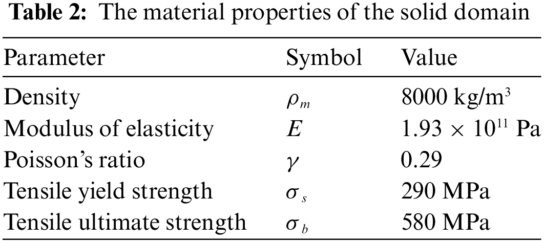
In the FSI analysis, the solid domain was used to analyze the structural response. The solid domain receives the data from the fluid domain and uses it for structural analysis. SOLIDWORKS 2020 software has been utilized to generate the solid domain, consisting of the rotating shaft and the rotating impeller. Moreover, the impeller includes the hub, shroud, and blades, as shown in Fig. 3. Table 2 shows the material properties utilized in the rotational part, and the material is stainless steel (DIN 1.4408) [18].

Figure 3: The solid domain of the centrifugal pump includes the impeller, rotating shaft, and cylindrical supports
2.2 Grid Generation and Grid Independence Verification
The poly-hexcore grid elements for all computational fluid domains were produced with ANSYS-Fluent Meshing, as shown in Fig. 4. The mesh has been refined near the wall to improve its quality and confirm that the chosen turbulence model is applicable. Hence, a boundary layer was used to verify that the dimensionless length from the wall surface, y+, was within an acceptable range. In this work, the maximum value of y+ is 89 for all computational domains, as shown in Fig. 5, which is good enough to satisfy the criteria of the numerical analysis [19–23].Verification of grid independence is essential to prevent grid number’s impact from influencing the flow simulation results. Hence, the divergence between the results of the numerical head in six grid cell numbers has been examined to ascertain and establish the optimal grid. Table 3 shows that the head error between the grids is less than 1%. Therefore, the impact of the grid number on computation can be disregarded. Fig. 6 depicts the percentage of head error of six computational grids under design conditions. The percentage of head error is almost constant on the fourth to sixth set of grids. After considering grid independence and the cost of computing, the fourth generated grid with 2616077 elements was ultimately chosen for numerical solution. In addition, the rotor system of the centrifugal pump has meshed with unstructured grids with 1010264 grid elements using ANSYS Meshing, as illustrated in Fig. 7.

Figure 4: Mesh of the fluid domain generated in the ANSYS-fluent meshing

Figure 5: Y+ at the centrifugal pump wall
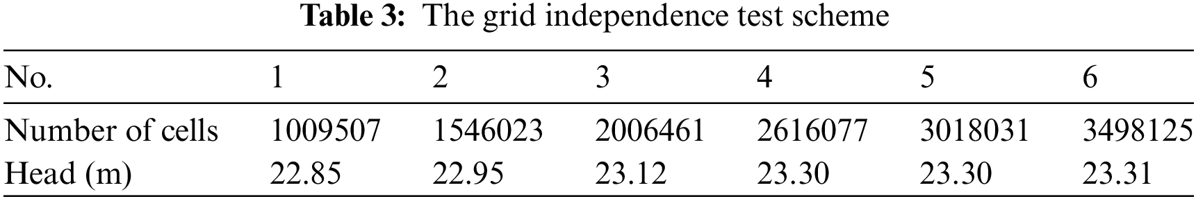

Figure 6: The mesh independence checking

Figure 7: The mesh of the solid domain
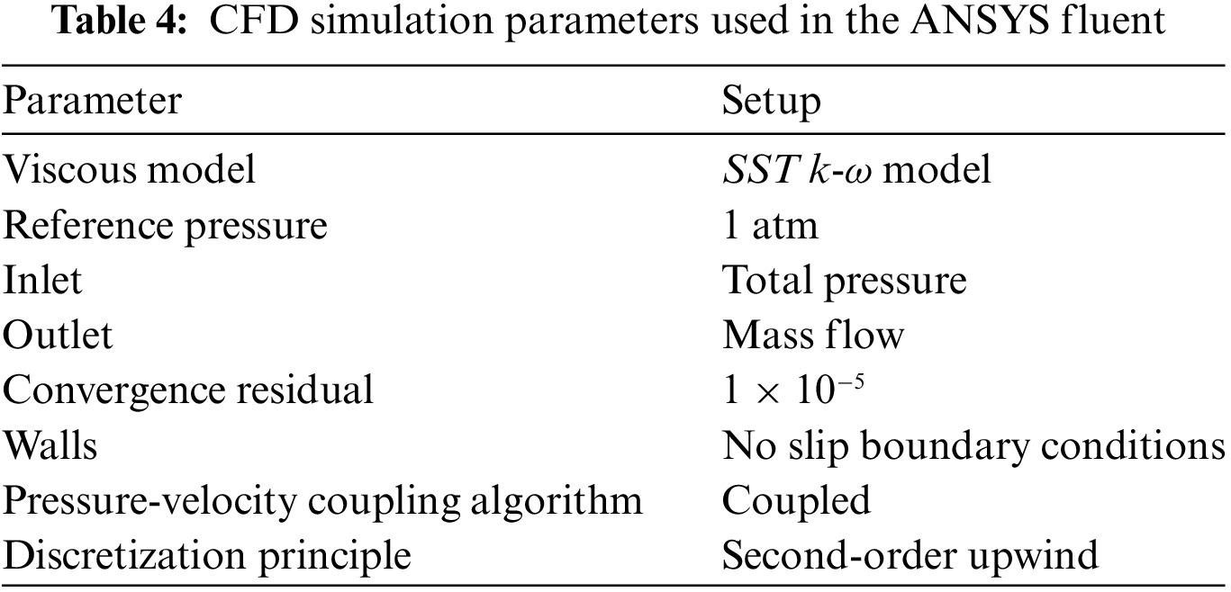
ANSYS Fluent 22R1 is employed to perform the numerical calculation. The turbulence model (SST k-ω) has been utilized to solve the unsteady Nevier-Stoke equations since it accurately predicts the flow near the wall [24–26]. The pressure-velocity coupling has been established through the implementation of the coupled algorithm. The discretization of momentum, turbulent kinetic energy, and specific dissipation rate was performed using the second-order upwind approach, whereas the pressure was discretized employing the PRESTO! Approach. In addition, the Green–Gauss Node-based technique has been used to calculate the gradients. The impeller region has been considered as the rotating domain with 1450 r/min; the rest were astatic domains. The turbulence intensity was established at an acceptable level, specifically at 5% intensity. The inlet boundary condition has been designated as total pressure, while the outlet boundary has been specified as mass flow. Furthermore, the no-slip condition was applied as the boundary condition at the wall of the computational domain (Table 4).
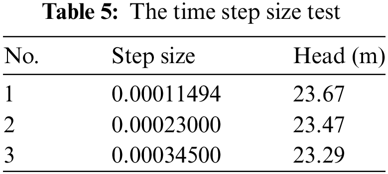
In fluid and structural analysis, the careful time step size has been selected [27,28]. The time step size can impact the results of the numerical solution because specific minor pressure changes cannot be caught if the time step size is too large. However, the small time step size can increase the computation time [29]. The time step independence has been tested by using the pump head under three different values to select the suitable time step size, including ∆t = 0.00011494, 0.00023, 0.000345 s, equivalent to (T/120, T/180, T/360) where T = 0.0414 s. The result concluded that with the variation of the time step size, the pump head’s divergence is less than 1.6%, as shown in Table 5. Therefore, considering the simulation time and precision, 0.000345 s was selected, which is 1/120 of the impeller rotational period T and with a 3° angle of the rotation per time step [18,30,31]. The convergence criteria are selected with 1 × 10⁻⁵ to test the result’s convergence during the simulation. Furthermore, the maximum number of iterations allotted for each time step has been modified to 10 to sustain residuals at an acceptable level of 10−5 [32].
3 The Procedure of the FSI Calculation
When the deformation of a structure caused by flow significantly affects the flow behavior, it becomes necessary to use a two-way coupling approach that integrates computational fluid dynamics (CFD) and computational solid dynamics (CSD) calculations. This methodology ensures a comprehensive representation of the phenomena under consideration. The present study adopts a partitioned approach for the strongly coupled solution, employing a two-way load transfer coupling method during the staggered solution procedure. This choice is made due to a distinct boundary separating the two domains, influencing the fluid and structure interaction. The ANSYS Workbench platform uses a system coupling component to connect the Finite Element Analysis (FEA) and CFD analysis systems. A time step of 0.000345 s is included in the system coupling to ensure temporal consistency between the two participating component systems. Two data transfers are established to facilitate the transmission of force data from the CFD system to the FEA system, as well as the transfer of incremental displacement from the FEA system to the CFD system, where it is used as mesh displacement. The areas contributing to data transmission are the fluid-solid interface boundary established at the blade surfaces in the FEA system, and the no-slip wall boundary consisting of the blade surfaces in CFD. The governing matrix equations [33,34] for finite elements are represented as follows:
where
4 Numerical Model of the Entropy Generation
Based on the Second Law of Thermodynamics, entropy generation is a parameter that describes the energy loss during the process of energy conversions according to irreversible factors. Therefore, entropy generation can be utilized within a numerical model to measure such energy loss for the flow of the centrifugal pumps. Consequently, it is reasonable to employ the entropy generation theory to fully address the hydraulic loss of the centrifugal pump [21,35–37]. Thermal gradients would be disregarded throughout the numerical examination; only the conservation of mass and momentum would be examined [38,39].
The flow field’s local entropy generation rate is defined as follows:
T, u, v, and
In the computation of the Reynolds time-average approach, the entropy creation induced by velocity field variations is unavailable. It may be easily derived from CFD findings [35].
In the computation of the k-ω model, the local entropy generation resulting from velocity field variations could be stated as:
where
where V explains the path of the fluid flow.
5.1 Validation and Performance Curve
To validate the accuracy of the results collected from the unsteady numerical simulation. The head coefficient ψ has been selected to verify the numerical results with the experimental data from [13]. The equation for the head coefficient is as follows:
The variable u2 represents the circumferential velocity of the impeller outlet, while g denotes the acceleration due to gravity.
Fig. 8 shows that although the experimental values are somewhat higher than the numerical findings of the head coefficient, both follow the same general pattern. Friction losses, inaccurate geometry, a hypothetical CFD model, and fluctuations in fluid properties might all contribute to this divergence [40,41]. The average error percentage between the current and experimental [14] results is only 1.69%. Thus, it indicated that the current simulation prediction is reliable and acceptable. Therefore, it can predict the head coefficient and simulate the flow in the centrifugal pump.

Figure 8: The validation of the head coefficient between experimental [14] and current simulation
The centrifugal pump’s hydraulic parameters, including pump head, shaft power, and pump efficiency, have been considered for various wrap blade angles. Fig. 9 shows the centrifugal pump’s head and shaft power for the six models. The head decreases with increasing the blade wrap angle, and the shaft power rises and then progressively declines once the blade wrap angle increases. Moreover, the following equation has been used to calculate the hydraulic efficiency for each of the six models:

Figure 9: The head and the shaft power vary with the blade wrap angle
where Psh represents the consumed shaft power.
Fig. 10 shows pump efficiency with a variety of blade wrap angles. The impeller exhibiting a blade wrap angle of 145° demonstrates the highest efficiency. Besides, using a 145° blade wrap angle also yielded the lowest shaft power. The reduced shaft power indicates that the energy transfer from the motor to the pump shaft is more efficient at a 145° blade wrap angle compared to other configurations. The enhanced efficiency can relate to minimized fluid friction and more effective utilization of the impeller’s geometry, resulting in a favorable balance between fluid acceleration and deceleration. Thus, the power required to transfer from the motor to the pump shaft is lesser than other blade wrap angles, which is more sustainable in power consumption.
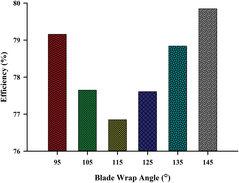
Figure 10: The pump efficiency at different blade wrap angles
5.2.1 Analysis of Frequency Domain
Fig. 11 displays the frequency domain graphic illustrating the static pressure pulsation at all monitoring points on the volute wall, considering different blade wrap angles. The pressure pulsation amplitude at each monitoring point is seen to occur at the Blade Passing Frequency (BPF), denoted as:


Figure 11: The frequency of the pressure fluctuation at the monitoring points (a) V1, (b) V2, (c) V3, and (d) V4
Z is the blade numbers, n is the rotational speed, and fb is the blade passing frequency [42].
The BPF is assessed to identify the vibration frequency component for different blade wrap angles. Since the impeller rotates at 1450 r/min, the rotating frequency (fb) of the six models (Table 6) specifies the magnitude of pressure pulsations at their fundamental frequencies. The difference in the domain frequencies of the blades’ pressure fluctuations can be attributed to their separation. The volute exhibits the highest amplitude of fluctuation pressure at the BPF for all monitoring locations, as seen in Fig. 2 in Section 2.1.1.

Moreover, the impeller with a 125° blade wrap angle peaks at monitoring points V1, V2, and V3 at the pump outlet. However, the impeller 135° blade wrap angle reaches the highest peak at monitoring point V4, far from the volute tongue. The analysis of the collected unsteady pressure data shows that the amplitude of the pressure pulsations is affected as the blade wrap angle rises. This spatial variation indicates a different pressure distribution pattern, emphasizing that the blade wrap angle influences the pressure characteristics at other locations within the pump system. As the blade wrap angle increases, an apparent effect on the amplitude of pressure pulsations becomes evident. This phenomenon indicates the relationship between the impeller geometry and fluid dynamics, where changes in the blade wrap angle influence the flow patterns, resulting in variations of pressure pulsations. Besides, the observed interpretations in pressure pulsations, contingent on changes in blade wrap angles, bear significant practical implications for the design and operation of the centrifugal pump. Understanding pressure pulsations has practical applications, from optimizing component durability to tailoring strategies for vibration and noise control. Engineers can use this information to design components capable of withstanding stress variations, improving overall system durability. Targeted measures can be implemented to dampen vibrations and minimize noise during pump operation by identifying blade wrap angles associated with heightened pressure pulsations at specific locations. The observed relationship also provides insights for operational adjustments, facilitating the optimization of pump efficiency and preventing cavitation.
To further study the internal flow behavior of the centrifugal pump, the middle section of the pump on the XY plane at Z = 0.05 m has been selected as the examination plane. Fig. 12 illustrates the cloud diagram showing the variations in static pressure as the blade wrap angle changes. The graph demonstrates that the difference in static pressure between the impeller input and impeller outlet is more pronounced for all models. The lowest static pressure area continuously exists at the impeller inlet, irrespective of differences in the blade wrap angle. As the impeller rotates, the pressure inside it rises, causing the pressure to expand as the radius increases. The increase in pressure results in a discernible static pressure differential within the impeller. The static pressure will gradually rise until it reaches its peak value upon entering the volute. The volute case’s presence and the volute tongue’s positioning substantially impact the flow characteristics, primarily due to the asymmetry they create. Although the effect of the volute tongue is evident, a highly uniform pressure distribution is observed around the impeller. The uneven characteristics of the pressure fields marked between the outer edge of the impeller and the volute resulted from the interaction between the rotor and stator. Examining the pressure distribution of six different impeller designs reveals that the pressure intensity over the impeller’s cross-section at each blade wrap angle degree varies as the blade wrap angle increases.

Figure 12: Static pressure distribution with blade wrap angle (a) 95°, (b) 105°, (c) 115°, (d) 125°, (e) 135° and (f) 145°
The results found that a 125° blade wrap angle has the highest pressure of the other models, which is clearly explained in Fig. 13. It can be seen that the impeller’s pressure with a 125° blade wrap angle has the highest pressure relative to the original model (115°). The larger blade wrap angle facilitates more efficient fluid acceleration and deceleration within the impeller, resulting in enhanced pressure generation. This is consistent with fluid dynamics principles, where a carefully selected blade wrap angle can optimize the pump’s performance by maximizing fluid kinetic energy transfer. The practical implication is the ability to strategically select blade wrap angles to maximize fluid kinetic energy transfer. This insight becomes invaluable for engineers and designers seeking to optimize pump performance, as carefully considering blade wrap angles can improve pressure distribution, enhance overall efficiency, and, ultimately, a more effective and reliable centrifugal pump system.

Figure 13: Static pressure values with blade wrap angle
5.3 Entropy Production Analysis
The total entropy generation of the centrifugal pump device at various blade wrap angles was calculated. The total entropy generation in each component of the centrifugal pump of the six models with several blade wrap angles (see Fig. 14). The distribution of the TEG on the pump components, i.e., inlet pipe, impeller, volute and outlet pipe (as shown in Fig. 1) are analyzed. Moreover, the proportion of the total entropy for each component of the centrifugal pump is shown in Fig. 15.

Figure 14: Distribution of TEG for pump components

Figure 15: The proportion of TEG for pump components
The analysis of the total entropy produced by the inlet and outlet pipes of the centrifugal pump and its impeller and volute revealed that the inlet pipe resulted in the least entropy loss across all cases. The observed pattern exhibited a sustained correlation with the rise in blade wrap angle. That means the pump’s inlet has little or no influence on the total entropy generation. However, the volute generated the maximum losses for all six models, followed by the outlet pipe. That indicates the volute is not a good pair or suitable for matching the impeller [43,44].
Moreover, the results of the total entropy of all centrifugal pump components (inlet and outlet pipes, impeller, and volute) show that wrap angles can affect the total entropy. The TEG of all components would be reduced by 0.58% with a 125° blade wrap angle and increased by 1.6% with a 145° blade wrap angle compared to the original geometry. The blade wrap angle is the only parameter considered to study its effect on the centrifugal pump performance when the other parameters are kept constant. The wrap angle is one of the impeller parameters, so comparing the results of its effect on the impeller on the TEG, as shown in Fig. 15. Fig. 15 demonstrates that the volute is responsible for around 63.85% to 66.18% of the proportion of entropy generation in all models. This suggests that most entropy generation occurs in the volute during operation. Besides, the high entropy generation in the volute is attributed to several factors. The volute, responsible for converting kinetic energy into pressure, experiences intense fluid deceleration and rise in pressure. This process inherently involves increased entropy, contributing to the observed entropy generation. The prominence of the volute in entropy generation has practical implications for pump design and efficiency optimization. Understanding and mitigating entropy generation in the volute enhances pump performance and minimizes energy losses.
5.3.2 Entropy Generation Rate (EGR)
The entropy generation rate is examined numerically under various blade wrap angles to provide a comprehensive understanding of the properties that constitute the energy lost by the centrifugal pump. Fig. 16 presents the EGR distribution under the six models. The EGR has startling irregularity in both the impeller and the volute. Fig. 16 demonstrates that the EGR in the region at the impeller inlet with 95° blade wrap angle is bigger than in the other models and fills almost the whole entrance of the impeller flow channel. Subsequently, the magnitude of the phenomenon mentioned above diminishes gradually until it reaches a point of near disappearance as the angle of the blade wrap experiences an increase.
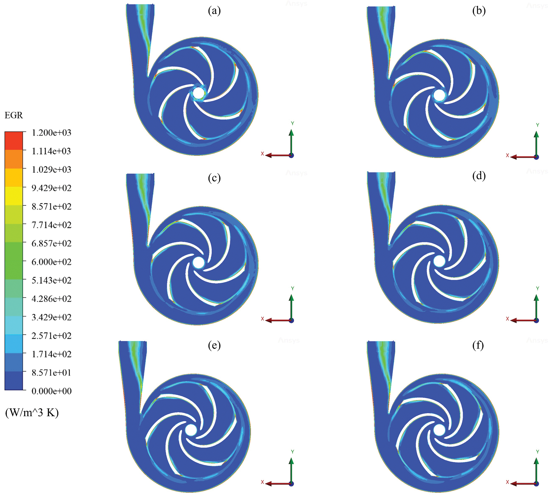
Figure 16: Distribution of EGR with blade wrap angle (a) 95°, (b) 105°, (c) 115°, (d) 125°, (e) 135° and (f) 145°
The trailing edge exhibits a higher level of entropy than the leading edge due to its lack of a rounded form. The volute and the blade demonstrate the highest level of entropy resulting from the frictional force the flow encounters. The location where the most entropy is seen is near the volute and the blade’s trailing edge. The backflow at the impeller outlet causes considerable energy loss at the blade trailing edge. The entropy generation rate can also be found at the impeller-volute interface since it is affected by rotor-stator interaction. Following fluid passage through the volute tongue, the subsequent occurrence of energy dissipation could be observed throughout the inner surface of the spiral region of the volute.
The losses are the most concentrated in the areas closest to the impeller’s inlet and outlet. Additionally, the amount of energy lost in the area close to the hub and the shroud is more than in the center part. As a result, the impeller-volute interface’s rotor-stator interaction significantly impacts the impeller inlet. Furthermore, it is essential to comprehend how the velocity profiles affect the EGR on various spans. There is a strong correlation between velocity streamlines and entropy distribution. From span 0.1 to span 0.95, the zones with high entropy levels had a similar velocity pattern. The blade-to-blade view provides a unique viewpoint for analyzing the flow between the blades at a fixed distance between the hub and shroud surfaces, as depicted in Fig. 17. As seen in Fig. 17, a diverse range of vortices are generated close to the impeller blades’ working surface, obstructing more than half of the impeller flow path and resulting in substantial energy dissipation. Despite vortices on the pressure surface, the low flow velocity causes the pressure surface to lose less energy than the suction surface. The blade wake flow also causes the loss at the exit of the impeller. The impeller’s suction side emerges as the primary determinant of the highest energy loss rate (EGR). The analysis at span 0.95 demonstrates an improvement in energy loss rate with increased blade wrap angle. This suggests that modifying the blade wrap angle can influence the flow dynamics and mitigate energy losses, particularly on the suction side of the impeller. Therefore, the impeller’s suction side (SS) determines the highest EGR, which improves with increased blade wrap angle, seen in span 0.95. The findings of the simulation are helpful for the engineer when refining the volute’s geometry and flow path to minimize entropy generation, thereby enhancing the pump’s overall efficiency. This understanding is crucial for designing energy-efficient centrifugal pumps, as minimizing entropy generation is synonymous with reducing energy losses and improving the system’s thermodynamic performance. Furthermore, the knowledge of specific blade wrap angles influencing entropy generation rates offers a practical avenue for tailoring pump configurations to meet efficiency goals.


Figure 17: EGR and velocity vector distribution in different spans with blade wrap angle (a) 95°, (b) 105°, (c) 115°, (d) 125°, (e) 135° and (f) 145°
5.4 Analysis of Structure Behavior
5.4.1 Analysis of Total Deformation
In the FSI simulation, the structural analysis was carried out using the ANSYS Mechanical, according to the data received from the fluid response. Fig. 18 illustrates the distribution diagram of structural deformation for various blade wrap angles. The maximum deflections are marked at the impeller outlet for all cases. The impeller is deformed around the edge region. The deformation gradually increases along the direction of the increasing radius of the impeller. In each model, the impeller’s outlet experiences the most significant deformation. The maximum deformation position of the impeller has a different trend for each model, and the deformation changes significantly. Variation of blade wrap angle has a significant effect on the maximum total deformation of the impeller. Fig. 18 clearly shows that the maximum deformation occurs in a different quadrant of the XY plane. The maximum deflection of a blade is subject to variation depending on changes in the blade wrap angle. It shows at the fourth quadrant of the impeller with 95°,105°, and 145° blade wrap angles. The maximum total deformation of the other cases (115°,125°, and 135°) has almost the same attuite. The maximum deflection is shown at the third quadrant of the XY plane. The impeller and fluid interaction is the primary mechanism driving impeller deformation. As fluid flows through the impeller blades, it imparts forces that induce structural deformations. The magnitude and distribution of these forces depend on the blade wrap angle, influencing the overall deformation pattern. Besides, variations in blade wrap angles influence the pressure distribution on the impeller’s surfaces. The pressure differences across the blades lead to asymmetric loading, contributing to differential deformations.

Figure 18: Total deformation distribution with blade wrap angle (a) 95°, (b) 105°, (c) 115°, (d) 125°, (e) 135° and (f) 145°
Fig. 19 depicts the maximum deformation variation curve for rotor systems with various blade wrap angles. The maximum total deformation exhibits a non-linear relationship with an increased blade wrap angle, first decreasing and then increasing (Fig. 19). This result demonstrates how the adjustment in blade wrap angle significantly altered the deformation of the rotor system. The maximum deformation exhibits significant variation across various blade wrap angles. Of the six impeller cases examined, the impeller featuring a blade wrap angle of 145° exhibited the highest degree of deformation, measuring 0.084 mm. The blade impeller with an angle of 115°, which is the initial design, indicates a minimum value of 0.074 mm. The observed non-linear trend signifies that adjustments in the blade wrap angle substantially impact the rotor system’s deformation characteristics. The initial decrease in deformation may attributed to a more favorable distribution of forces and stresses within the rotor structure at certain blade wrap angles. However, as the blade wrap angle continues to increase, a point is reached where the structural response is influenced differently, leading to an increase in deformation. This highlights the critical role of the blade wrap angle in determining the structural integrity and deformation characteristics of the rotor system.

Figure 19: The maximum value of a total deformation for different blade wrap angles
In the current simulation, a System Coupling in Ansys Workbench has been utilized to consider the influence of structural deformation on the flow field, as shown in Fig. 20. The computational solid dynamics promptly transferred displacement data to the computational fluid dynamics solver. Notably, our examination indicates that the total deformation of the structure falls within a narrow range of 0.074 to 0.084 mm. The subtle deformations in the structure have resulted in a nuanced impact, making the observable effects on the flow field less apparent during the simulation. The minor structural alterations have introduced complexities that render the influence on the flow field more challenging to discern within the simulation environment.

Figure 20: FSI simulations with two-way coupling
5.4.2 Analysis of Equivalent Stress
Fig. 21 illustrates the impeller’s equivalent stress distribution for various blade wrap angles. Relative stress values at the impeller are highest at the root of the blade junction, with a hub for all cases. The impeller’s equivalent stress distribution remains consistent and center-symmetric across varying blade wrap angles. The arrangement of the hub joint and the impeller blades clearly show stress concentration areas. Moreover, the maximum value of the equivalent stress of all testing models is shown at the cylindrical support: A rotating shaft that closes to the rotating impeller of the centrifugal pump, as shown in Fig. 22. The impeller’s interaction with the fluid during operation induces forces on the blades, leading to stress distribution. The mechanism involves fluid forces acting on the impeller surfaces, resulting in stress concentrations at critical regions.

Figure 21: Equivalent stress distribution at the impeller with blade wrap angle (a) 95°, (b) 105°, (c) 115°, (d) 125°, (e) 135° and (f) 145°


Figure 22: Equivalent stress distribution at support: A with blade wrap angle (a) 95°, (b) 105°, (c) 115°, (d) 125°, (e) 135° and (f) 145°
Fig. 23 shows the curve of the maximum equivalent stress of the solid rotating structure of the centrifugal pump. The solid structure’s maximum equivalent stress changes significantly as the blade wrap angle rises. The maximum equivalent stress of the impeller with a 145° blade wrap angle was not much higher than in other cases, with a value of 14.8 MPa. Moreover, the impeller with a 115° blade wrap angle shows a minimum value of 12.79 MPa. The observed stress distribution trends indicate a relationship between the blade wrap angle and the structural response of the solid rotating structure. The modest increase in maximum equivalent stress at a 145° blade wrap angle may attributed to the interactions between the impeller’s geometry and the fluid forces acting upon it. Hence, a similar trend is observed in the total deformation results, as discussed in Fig. 19.

Figure 23: Maximum equivalent stress with a blade wrap angle
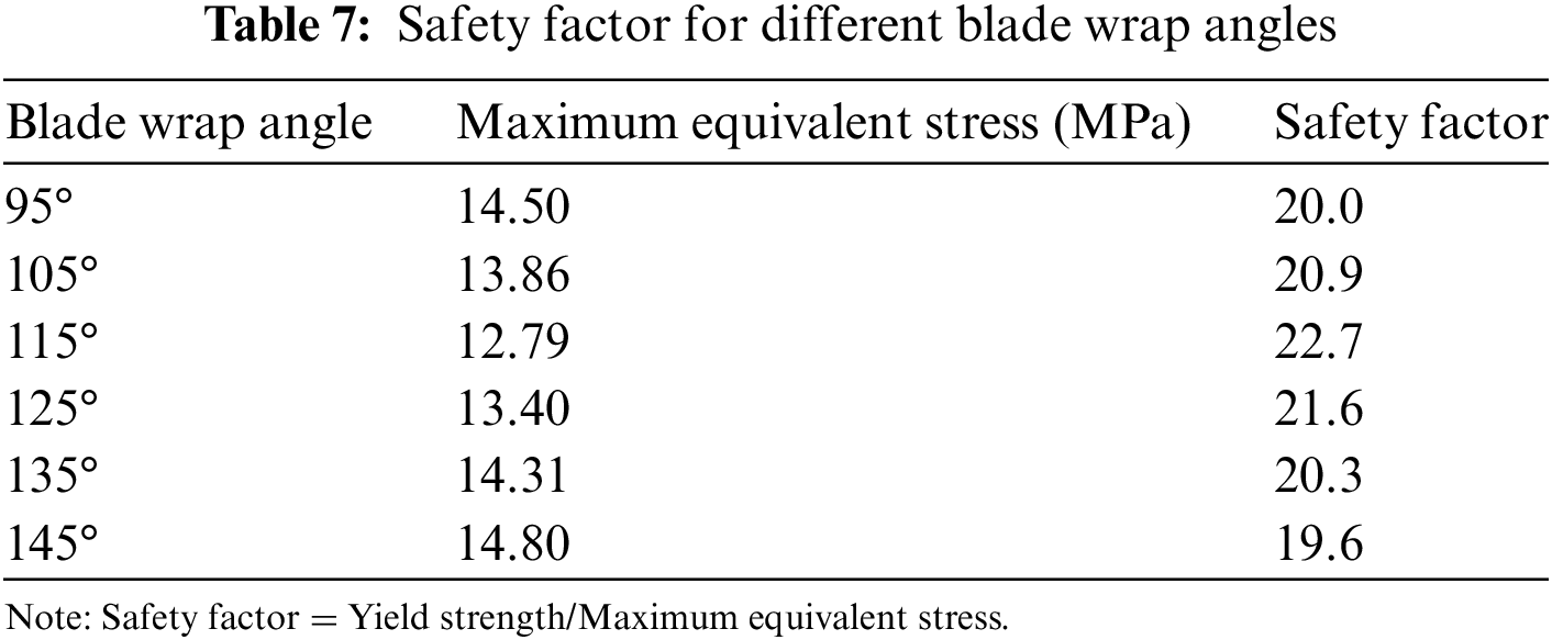
The safety and reliability analysis of the centrifugal pump impeller’s equivalent stress distribution is integral to ensuring the robustness and dependability of the pump system. In Fig. 21, the observed stress distribution patterns indicate areas of potential concern, particularly at the root of the blade junction and the hub. The tensile yield strength and tensile ultimate strength given in Table 2 are 290 and 580 MPa, respectively. Any equivalent stress on the structures (impeller, rotating shaft, and cylindrical supports) that exceeds the yield strength will lead to permanent deformation and failure when it exceeds the ultimate strength. Therefore, the stress endured by the structure must not exceed both yield strength and ultimate strength. The safety factor (ratio between yield strength and the maximum equivalent stress) of the structure is calculated and summarized in Table 7. The safety factor for all cases is more than 19, which indicates that the applied stress on the structure is significantly lower than the yield strength of the material. Thus, the structure or component is designed with a substantial margin of safety, providing a very high reliability and strength. Besides, a safety factor greater than 19 indicates that the structure or component has a considerable amount of excess strength with a high level of structural integrity and reduced risk of failure or deformation, even under extreme conditions. While a high safety factor is generally desirable for ensuring safety and reliability, it is crucial to strike a balance between safety and cost-effectiveness. Extremely high safety factors may lead to overdesign, and engineers often optimize designs carefully, considering various factors, including material properties, loading conditions, and economic considerations. The safety and reliability analysis, when seamlessly integrated into the overall assessment of the centrifugal pump, not only addresses potential failure modes but also contributes to the continuous improvement of the pump’s performance, durability, and operational safety.
In this paper, the impact of the variation of the blade wrap angle on internal flow and structural behavior by employing the fluid-structure interaction and entropy generation theory in a centrifugal pump has been investigated and analyzed numerically. A numerical investigation of the centrifugal pump’s hydraulic performance reveals that the head decreases as the blade wrap angle rises. The impeller’s shaft power increases steadily, reaching the maximum value when the blade wrap angle is 115° (original model), then gradually falls. Differing blade wrap angles may affect centrifugal pump performance, i.e., the greater the blade wrap angle, the better the efficiency.
The findings indicate that the amplitude of the pressure pulsations is affected as the blade wrap angle rises. The most considerable amplitude pressure fluctuation would be at monitoring points V1, V2, and V3 were seen to occur at an angle of 125°. However, the impeller with a 135° angle reaches the highest peak at V4. By analyzing the entropy generation theory, it is found that the highest value of total entropy was detected at the volute. The location of the area with an elevated generation of entropy on the surface with a span value of 0.95 is identified to be at the SS. The entropy generation on the SS rises near the shroud due to the rise in velocity relative to the shroud.
The impeller’s maximum equivalent stress and maximum total deformation in all models are more extensive than that in the original model (115°). The maximum impeller diameter is where the highest overall distortion is found. In all cases, the root of the blade’s junction with the hub is where the impeller’s maximum equivalent stress is located. The highest equivalent stress of all testing models is displayed at the cylindrical support. The occurrence of deformation is permissible as the maximum equivalent stress is much below the tensile yield strength of the material.
Due to research limitations, this study utilized entropy generation and two-way fluid-structure coupling to simulate the blade wrap angle’s effect. These methods must be employed in the subsequent investigation to determine how other centrifugal factors affect fluid domain, structural deformation, and flow system energy dissipation. Furthermore, the limited processing capability restricts the extent of detail or complexity achieved in the simulation, especially when including two-way fluid-structure coupling in the current research. Integrating the two-way fluid-structure coupling method is essential for enhancing the investigation of centrifugal pump performance. Future studies can incorporate fluid-structure interaction features to investigate the impact of additional parameters, making it a prominent trend in the analysis of centrifugal pumps.
Acknowledgement: The authors express their gratitude to Universiti Sains Malaysia, Malaysia and Al-Muthanna University, Iraq for extending technical assistance.
Funding Statement: The authors are grateful to the Division of Research & Innovation (R&I), Universiti Sains Malaysia for their fund support.
Author Contributions: The authors confirm their contribution to the paper as follows: study conception and design: H. Sakran, M. Abdul Aziz; data collection: H. Sakran; analysis and interpretation of results: H. Sakran, M. Abdul Aziz; draft manuscript preparation: C. Khor. All authors reviewed the results and approved the final version of the manuscript.
Availability of Data and Materials: The data that support the findings of this study are available on request from the corresponding author.
Conflicts of Interest: The authors declare that they have no conflicts of interest to report regarding the present study.
References
1. Yang, W., Wu, Y. L., Liu, S. H. (2011). An optimization method on runner blades in bulb turbine based on CFD analysis. Science China Technological Sciences, 54(2), 338–344. https://doi.org/10.1007/s11431-010-4261-4 [Google Scholar] [CrossRef]
2. Sakran, H. K., Abdul Aziz, M. S., Abdullah, M. Z., Khor, C. Y. (2022). Effects of blade number on the centrifugal pump performance: A review. Arabian Journal for Science and Engineering, 47, 7945–7961. https://doi.org/10.1007/s13369-021-06545-z [Google Scholar] [CrossRef]
3. Tan, L., Zhu, B., Cao, S., Bing, H., Wang, Y. (2014). Influence of blade wrap angle on centrifugal pump performance by numerical and experimental study. Chinese Journal of Mechanical Engineering, 27(1), 171–177. https://doi.org/10.3901/CJME.2014.01.171 [Google Scholar] [CrossRef]
4. Tan, M., Ji, Y., Liu, H., Wu, X., Zhu, Z. (2018). Effect of blade wrap angle on performance of a single-channel pump. Experimental Techniques, 42(5), 481–490. https://doi.org/10.1007/s40799-018-0243-4 [Google Scholar] [CrossRef]
5. Yang, S. S., Kong, F. Y., Jiang, W. M., Qu, X. Y. (2012). Effects of impeller trimming influencing pump as turbine. Computers and Fluids, 67, 72–78. https://doi.org/10.1016/j.compfluid.2012.07.009 [Google Scholar] [CrossRef]
6. Tan, L., Yang, Y., Shi, W., Chen, C., Xie, Z. (2021). Influence of blade wrap angle on the hydrodynamic radial force of single blade centrifugal pump. Applied Sciences, 11(19), 9052. https://doi.org/10.3390/app11199052 [Google Scholar] [CrossRef]
7. Gao, X., Zhao, T., Shi, W., Zhang, D., Shi, Y. et al. (2020). Numerical investigation of an open-design vortex pump with different blade wrap angles of impeller. Processes, 8(12), 1–19. https://doi.org/10.3390/pr8121601 [Google Scholar] [CrossRef]
8. Liang, D., Yuqi, Z., Houlin, L., Cui, D., Vladimirovich, G. D. et al. (2018). The effect of front streamline wrapping angle variation in a super-low specific speed centrifugal pump. Proceedings of the Institution of Mechanical Engineers, Part C: Journal of Mechanical Engineering Science, 232(23), 4301–4311. https://doi.org/10.1177/0954406218772605 [Google Scholar] [CrossRef]
9. Hao, Z., Ren, W., Xu, J., Zhang, H., Wang, Y. (2020). Performance analysis of single-channel pump with different wrap angles. Journal of Physics: Conference Series, 1570(1), 6–11. https://doi.org/10.1088/1742-6596/1570/1/012077 [Google Scholar] [CrossRef]
10. Du, J., Yang, H., Shen, Z. (2018). Study on the impact of blades wrap angle on the performance of pumps as turbines used in water supply system of high-rise buildings. International Journal of Low-Carbon Technologies, 13(1), 102–108. https://doi.org/10.1093/ijlct/cty002 [Google Scholar] [CrossRef]
11. Wang, Y., Liu, H., Liu, D., Wang, J., Wu, X. (2013). Effects of vane wrap angle on flow induced vibration and noise of centrifugal pumps. Transactions of the Chinese Society of Agricultural Engineering, 29(1), 72–77. [Google Scholar]
12. Bai, Y., Kong, F., Yang, S., Chen, K., Dai, T. (2017). Effect of blade wrap angle in hydraulic turbine with forward-curved blades. International Journal of Hydrogen Energy, 42(29), 18709–18717. https://doi.org/10.1016/j.ijhydene.2017.04.185 [Google Scholar] [CrossRef]
13. Zhang, N., Gao, B., Li, Z., Ni, D., Jiang, Q. (2018). Unsteady flow structure and its evolution in a low specific speed centrifugal pump measured by PIV. Experimental Thermal and Fluid Science, 97, 133–144. https://doi.org/10.1016/j.expthermflusci.2018.04.013 [Google Scholar] [CrossRef]
14. Zhang, N., Yang, M., Gao, B., Li, Z., Ni, D. (2016). Investigation of rotor-stator interaction and flow unsteadiness in a low specific speed centrifugal pump. Strojniski Vestnik/Journal of Mechanical Engineering, 62(1), 21–31. https://doi.org/10.5545/sv-jme.2015.2859 [Google Scholar] [CrossRef]
15. Ghorani, M. M., Sotoude Haghighi, M. H., Maleki, A., Riasi, A. (2020). A numerical study on mechanisms of energy dissipation in a pump as turbine (PAT) using entropy generation theory. Renewable Energy, 162, 1036–1053. https://doi.org/10.1016/j.renene.2020.08.102 [Google Scholar] [CrossRef]
16. Maleki, A., Ghorani, M. M., Haghighi, M. H. S., Riasi, A. (2020). Numerical study on the effect of viscosity on a multistage pump running in reverse mode. Renewable Energy, 150, 234–254. https://doi.org/10.1016/j.renene.2019.12.113 [Google Scholar] [CrossRef]
17. Yang, S. S., Kong, F. Y., Chen, H., Su, X. H. (2012). Effects of blade wrap angle influencing a pump as turbine. Journal of Fluids Engineering, 134(6), 1–8. https://doi.org/10.1115/1.4006677 [Google Scholar] [CrossRef]
18. Wu, D., Ren, Y., Mou, J., Gu, Y., Jiang, L. (2019). Unsteady flow and structural behaviors of centrifugal pump under cavitation conditions. Chinese Journal of Mechanical Engineering, 32(1), 17. https://doi.org/10.1186/s10033-019-0328-8 [Google Scholar] [CrossRef]
19. Zhang, H., Meng, F., Cao, L., Li, Y., Wang, X. (2022). The influence of a pumping chamber on hydraulic losses in a mixed-flow pump. Processes, 10(2). https://doi.org/10.3390/pr10020407 [Google Scholar] [CrossRef]
20. Wang, C., Zhang, Y., Hou, H., Yuan, Z., Liu, M. (2020). Optimization design of an ultra-low specific-speed centrifugal pump using entropy production minimization and taguchi method. International Journal of Fluid Machinery and Systems, 13(1), 55–67. https://doi.org/10.5293/IJFMS.2019.13.1.055 [Google Scholar] [CrossRef]
21. Li, J., Meng, D., Qiao, X. (2020). Numerical investigation of flow field and energy loss in a centrifugal pump as turbine. Shock and Vibration, 2020. https://doi.org/10.1155/2020/8884385 [Google Scholar] [CrossRef]
22. Zhao, W., Zhao, G. (2017). An active method to control cavitation in a centrifugal pump by obstacles. Advances in Mechanical Engineering, 9(11), 1–15. https://doi.org/10.1177/1687814017732940 [Google Scholar] [CrossRef]
23. Liu, Y., Tan, L. (2019). Spatial-temporal evolution of tip leakage vortex in a mixed-flow pump with tip clearance. Journal of Fluids Engineering, Transactions of the ASME, 141(8), 081302. https://doi.org/10.1115/1.4042756 [Google Scholar] [CrossRef]
24. Pei, J., Osman, M. K., Wang, W., Yuan, J., Yin, T. et al. (2020). Unsteady flow characteristics and cavitation prediction in the double-suction centrifugal pump using a novel approach. Proceedings of the Institution of Mechanical Engineers, Part A: Journal of Power and Energy, 234(3), 283–299. https://doi.org/10.1177/0957650919863636 [Google Scholar] [CrossRef]
25. Li, D., Qin, Y., Zuo, Z., Wang, H., Liu, S. et al. (2019). Numerical simulation on pump transient characteristic in a model pump turbine. Journal of Fluids Engineering, 141(11), 111101. https://doi.org/10.1115/1.4043496 [Google Scholar] [CrossRef]
26. Wang, Y., Zhang, F., Yuan, S., Chen, K., Wei, X. et al. (2020). Effect of URANS and hybrid RANS-large eddy simulation turbulence models on unsteady turbulent flows inside a side channel pump. Journal of Fluids Engineering, 142(6), 061503. https://doi.org/10.1115/1.4045995 [Google Scholar] [CrossRef]
27. Yuan, S., Pei, J., Yuan, J. (2011). Numerical investigation on fluid structure interaction considering rotor deformation for a centrifugal pump. Chinese Journal of Mechanical Engineering, 24(4), 539–545. https://doi.org/10.3901/CJME.2011.04.539 [Google Scholar] [CrossRef]
28. Huang, H., Liu, H., Wang, Y., Dai, H., Jiang, L. (2014). Stress-strain and modal analysis on rotor of marine centrifugal pump based on fluid-structure interaction. Transactions of the Chinese Society of Agricultural Engineering, 30(15), 98–105. [Google Scholar]
29. Bai, L., Zhou, L., Han, C., Zhu, Y., Shi, W. (2019). Numerical study of pressure fluctuation and unsteady flow in a centrifugal pump. Processes, 7(6), 354. https://doi.org/10.3390/pr7060354 [Google Scholar] [CrossRef]
30. Jian, W., Yong, W., Houlin, L., Qiaorui, S., Dular, M. (2018). Rotating corrected-based cavitation model for a centrifugal pump. Journal of Fluids Engineering, 140(11), 111301. https://doi.org/10.1115/1.4040068 [Google Scholar] [CrossRef]
31. Al-Obaidi, A. R. (2019). Monitoring the performance of centrifugal pump under single-phase and cavitation condition: A CFD analysis of the number of impeller blades. Journal of Applied Fluid Mechanics, 12(2), 445–459. https://doi.org/10.29252/jafm.12.02.29303 [Google Scholar] [CrossRef]
32. Karanth, K. V., Sharma, N. Y. (2009). Numerical analysis on the effect of varying number of diffuser vanes on impeller−diffuser flow interaction in a centrifugal fan. World Journal of Modelling and Simulation, 5(1), 63–71. [Google Scholar]
33. Zhou, B., Yuan, J., Fu, Y., Hong, F., Lu, J. (2016). Investigation of dynamic stress of rotor in residual heat removal pumps based on fluid-structure interaction. Advances in Mechanical Engineering, 8(9), 1–12. https://doi.org/10.1177/1687814016665746 [Google Scholar] [CrossRef]
34. Zhou, B., Yuan, J., Lu, J., Hong, F. (2017). Investigation on transient behavior of residual heat removal pumps in 1000 MW nuclear power plant using a 1D-3D coupling methodology during start-up period. Annals of Nuclear Energy, 110, 560–569. https://doi.org/10.1016/j.anucene.2017.07.013 [Google Scholar] [CrossRef]
35. Cui, B., Li, J., Zhang, C., Zhang, Y. (2020). Analysis of radial force and vibration energy in a centrifugal pump. Mathematical Problems in Engineering, 2020. https://doi.org/10.1155/2020/6080942 [Google Scholar] [CrossRef]
36. Guan, H., Jiang, W., Yang, J., Wang, Y., Zhao, X. et al. (2020). Energy loss analysis of the double-suction centrifugal pump under different flow rates based on entropy production theory. Proceedings of the Institution of Mechanical Engineers, Part C: Journal of Mechanical Engineering Science, 234(20), 4009–4023. https://doi.org/10.1177/0954406220919795 [Google Scholar] [CrossRef]
37. Sheikholeslami, M., Ellahi, R., Shafee, A., Li, Z. (2019). Numerical investigation for second law analysis of ferrofluid inside a porous semi annulus: An application of entropy generation and exergy loss. International Journal of Numerical Methods for Heat & Fluid Flow, 29(3), 1079–1102. [Google Scholar]
38. Gu, Y., Pei, J., Yuan, S., Wang, W., Zhang, F. et al. (2019). Clocking effect of vaned diffuser on hydraulic performance of high-power pump by using the numerical flow loss visualization method. Energy, 170, 986–997. https://doi.org/10.1016/j.energy.2018.12.204 [Google Scholar] [CrossRef]
39. Yang, J., Pavesi, G., Liu, X., Xie, T., Liu, J. (2018). Unsteady flow characteristics regarding hump instability in the first stage of a multistage pump-turbine in pump mode. Renewable Energy, 127, 377–385. https://doi.org/10.1016/j.renene.2018.04.069 [Google Scholar] [CrossRef]
40. Tan, L., Zhu, B. S., Cao, S. L., Wang, Y. M. (2013). Cavitation flow simulation for a centrifugal pump at a low flow rate. Chinese Science Bulletin, 58(8), 949–952. https://doi.org/10.1007/s11434-013-5672-y [Google Scholar] [CrossRef]
41. Liu, H. L., Liu, D. X., Wang, Y., Wu, X. F., Wang, J. (2013). Application of modified k-ω model to predicting cavitating flow in centrifugal pump. Water Science and Engineering, 6(3), 331–339. https://doi.org/10.3882/j.issn.1674-2370.2013.03.009 [Google Scholar] [CrossRef]
42. Gao, Z., Zhu, W., Lu, L., Deng, J., Zhang, J. et al. (2014). Numerical and experimental study of unsteady flow in a large centrifugal pump with stay vanes. Journal of Fluids Engineering, 136(7), 071101. https://doi.org/10.1115/1.4026477 [Google Scholar] [CrossRef]
43. Hou, H., Zhang, Y., Li, Z. (2017). A numerical research on energy loss evaluation in a centrifugal pump system based on local entropy production method. Thermal Science, 21(3), 1287–1299. https://doi.org/10.2298/TSCI150702143H [Google Scholar] [CrossRef]
44. Huang, P., Appiah, D., Chen, K., Zhang, F., Cao, P. et al. (2021). Energy dissipation mechanism of a centrifugal pump with entropy generation theory. AIP Advances, 11(4), 045208. https://doi.org/10.1063/5.0042831 [Google Scholar] [CrossRef]
Cite This Article
 Copyright © 2024 The Author(s). Published by Tech Science Press.
This work is licensed under a Creative Commons Attribution 4.0 International License , which permits unrestricted use, distribution, and reproduction in any medium, provided the original work is properly cited.
 Downloads
 Citation Tools