
 Submit a Paper
 Propose a Special lssue
 Open Access
ARTICLE

Multi-Objective Optimization of Aluminum Alloy Electric Bus Frame Connectors for Enhanced Durability
1 Key Laboratory of Traffic Safety on Track, Ministry of Education, School of Traffic & Transportation Engineering, Central South University, Changsha, 410018, China
2 School of Mechanical and Automotive Engineering, Xiamen University of Technology, Xiamen, 361024, China
* Corresponding Author: Yong Peng. Email:
(This article belongs to the Special Issue: Structural Design and Optimization)
Computer Modeling in Engineering & Sciences 2024, 140(1), 735-755. https://doi.org/10.32604/cmes.2024.047258
Received 31 October 2023; Accepted 18 January 2024; Issue published 16 April 2024
 View Full Text
 Download PDF
Abstract
The widespread adoption of aluminum alloy electric buses, known for their energy efficiency and eco-friendliness, faces a challenge due to the aluminum frame’s susceptibility to deformation compared to steel. This issue is further exacerbated by the stringent requirements imposed by the flammability and explosiveness of batteries, necessitating robust frame protection. Our study aims to optimize the connectors of aluminum alloy bus frames, emphasizing durability, energy efficiency, and safety. This research delves into Multi-Objective Coordinated Optimization (MCO) techniques for lightweight design in aluminum alloy bus body connectors. Our goal is to enhance lightweighting, reinforce energy absorption, and improve deformation resistance in connector components. Three typical aluminum alloy connectors were selected and a design optimization platform was built for their MCO using a variety of software and methods. Firstly, through three-point bending experiments and finite element analysis on three types of connector components, we identified optimized design parameters based on deformation patterns. Then, employing Optimal Latin hypercube design (OLHD), parametric modeling, and neural network approximation, we developed high-precision approximate models for the design parameters of each connector component, targeting energy absorption, mass, and logarithmic strain. Lastly, utilizing the Archive-based Micro Genetic Algorithm (AMGA), Multi-Objective Particle Swarm Optimization (MOPSO), and Non-dominated Sorting Genetic Algorithm (NSGA2), we explored optimized design solutions for these joint components. Subsequently, we simulated joint assembly buckling during bus rollover crash scenarios to verify and analyze the optimized solutions in three-point bending simulations. Each joint component showcased a remarkable 30%–40% mass reduction while boosting energy absorption. Our design optimization method exhibits high efficiency and cost-effectiveness. Leveraging contemporary automation technology, the design optimization platform developed in this study is poised to facilitate intelligent optimization of lightweight metal components in future applications.Keywords
Nomenclature
| MCO | Multi-objective coordinated optimization |
| AMGA | Archive-based micro genetic algorithm |
| OLHD | Optimal latin hypercube design |
| MOPSO | Multi-objective particle swarm optimization |
| NSGA2 | Non-dominated sorting genetic algorithm |
| RBF | Radial basis function |
| EA | Energy absorption |
| LE | Strain |
In response to the goals of energy conservation and environmental protection, the development of new energy vehicles, where power batteries gradually replace petroleum-driven models, has experienced rapid growth. Similarly, in the realm of buses, pure electric buses have gradually replaced conventional ones. To alleviate the vehicle’s weight and relieve driving pressure, pure electric buses adopt lightweight alloy frames such as aluminum and magnesium alloys. Due to lower costs, the application of all-aluminum alloy frames is more widespread. Aluminum alloy materials offer various advantages, including low density, high toughness, greater specific strength, and superior energy absorption capability [1]. These characteristics render aluminum alloys as ideal lightweight materials, especially suitable for new energy buses.
Aluminum alloy electric buses commonly utilize Mechanical Composite Connection Technology (MCCT) for frame connections. This is due to aluminum alloy’s low thermal capacity, high thermal conductivity, and significant electrical conductivity. Traditional welding methods applied to aluminum alloy materials tend to result in undesirable welding effects, shortened electrode life, and unstable joint quality. Consequently, the aluminum alloy manufacturing sector has adopted innovative connection technologies to overcome these obstacles. One such technology is MCCT, connecting the bus frame using screw or rivet components. Relative to screw connections, riveting technology is relatively simple, cost-effective, and less susceptible to challenges like torque degradation and thread failure, making it a more feasible option. Hence, combining MCCT with connecting components and riveting technology stands as a practical solution [2].
Connectors in the aluminum alloy electric bus body structure serve as critical load-bearing components, and their intricate force distribution significantly impacts the overall structural performance of the bus frame. Although aluminum alloy frames have numerous advantages over steel frames, such as lighter weight and corrosion resistance, they are more prone to deformation and incur higher costs. In some collisions and rollover accidents, aluminum alloy electric bus frames exhibit significant deformation, which profoundly affects passenger safety and operational costs. Therefore, enhancing the durability of aluminum alloy electric buses is of considerable value. Among various methods to improve the durability of aluminum alloy frames, optimizing connection structures stands as one of the most cost-effective approaches.
It is worth noting that extensive research has been conducted in the academic community on the mechanical properties of key joints in bus frames, providing a solid foundation for subsequent optimization design [3]. Through rollover testing and LS-DYNA numerical simulation, Liang et al. [4] discovered that the superstructure of Bus A is susceptible to strong impact at the corner where the side and roof are connected. The window posts and side wall reinforcement on both sides of the frame are identified as main components with high A value and strong energy absorption capacity. This finding also offers guidance for selecting key connection parts for aluminum alloy frames in this study. In terms of connector research, Cho et al. [3] investigated the shear lag effect of bolted connections using aluminum alloy angle steel and performed reliability estimation on design specifications related to tensile capacity across various net sections [5]. Zhang et al. designed two novel gusset joints made from aluminum alloy. Parametric studies were conducted based on a validated FE model to examine how key parameters, such as gusset plate shape, fastener preload, angle shear connector configurations, pin number, and layout, influence the structural performance of these innovative gusset joints. Finally, the reliability of these novel gusset joints was demonstrated.
Against this backdrop, existing research findings collectively discovered a consistent theme: in side collision and rollover simulation calculations, the connection structure between the bus frame pillars, roof, waist beam, and crossbeam exhibit unique attributes, tending towards significant deformation with relatively lower rigidity levels. From previous studies, it is evident that effectively coordinating lightweight structures, deformation management, and energy absorption—these three competing objectives—is crucial for optimizing aluminum alloy electric bus connection structures [6].
Efficiently conducting multi-objective optimization on aluminum alloy electric bus connection structures, substituting traditional experiments with approximate models and multi-objective optimization algorithms, stands as one of the most advocated methods currently. In this context, contemporary intelligent optimization algorithms rooted in swarm intelligence have gained prominence. These algorithms include Genetic Algorithms, Particle Swarm Optimization, NSGA2, and Artificial Bee Colony [7]. By mapping the design space into the objective space, these algorithms generate a Pareto solution set, comprehensively reflecting subtle differences in actual problems, simultaneously enhancing convergence accuracy and efficiency, cleverly managing complex multi-objective optimizations. For instance, Zhong et al. applied NSGA2 to optimize the car body frame structure [8], while Navinje et al. employed NSGA-II for similar purposes, and Wang et al. introduced an improved NSGA2 combined with technique for ordering preferences by similarity to ideal solution (TOPSIS) for the lightweight design of the front subframe [9].
Furthermore, to enhance optimization efficiency, scholars advocate integrating optimization algorithms with approximate models to promote multi-objective optimization design. For example, Gao et al. [10] employed a combination of Latin Sampling, Kriging approximate models, and PSO algorithms for optimizing the collision performance of passenger car bodies. Chen’s work [11] introduced a multi-objective optimization method using Adaptive Radial Basis Models, appropriately balancing energy absorption and collision force peak in thin-walled body components. This innovation significantly improved collision safety performance and simulation efficiency. Building on this, Yin et al. [12] conducted multi-objective optimization design for the electric vehicle body-in-white, employing a global response surface method to optimize weight and bending stiffness simultaneously.
Significantly, most studies to date have centered around traditional steel body frames. Research focused on optimizing aluminum alloy electric bus connection structures is remarkably limited. Thus, to deepen the study of aluminum alloy bus frame connection architecture, this paper conducts MCO of connectors to enhance the durability of aluminum alloy frames. By enhancing the lightweight, energy absorption, and deformation resistance of riveted aluminum alloy connection components through multi-objective coordinated optimization, this paper lays a solid foundation. Based on quasi-static three-point bending experiments, detailed verification of finite element models of connection structures and analysis of deformation patterns were carried out. The OLHD was employed to explore the optimal design range and establish high-precision approximate models, improving modeling efficiency. Three multi-objective optimization algorithms were then used to obtain optimal optimization solutions.
The material experiments and bending experiments are covered in Sections 2.1 and 2.2, while the simulation modeling and verification results are analyzed in Sections 2.3 and 2.4. Parametric modeling is discussed in Section 3.1, sampling and establishing approximate models are focused on in Section 3.2, determining multi-objective optimization equations and deriving optimized solutions are addressed in Section 3.3, and a comparative analysis of three optimization schemes along with their original design schemes for each connection using finite element simulation is provided in Section 3.4 before concluding the paper.
2.1 Connectors for Aluminum Alloy Pure Electric Bus Frames
The bus model used in this study is an all-aluminum pure electric bus comprising a front section and four body sections, measuring 12 meters in total length and accommodating 48 seats. Our research focuses on the aluminum alloy frame in the middle section, widely recognized as the most mechanically vulnerable part [13]. As depicted in Fig. 1a, this section’s frame consists of three key components: the roof, sidewalls, and underframe. The aluminum frames of the roof, sidewalls, and body pillars are commonly connected using MCCT. As illustrated in Fig. 1b, the connectors utilized in these connections are designated as Part A, Part B, and Part C, respectively.
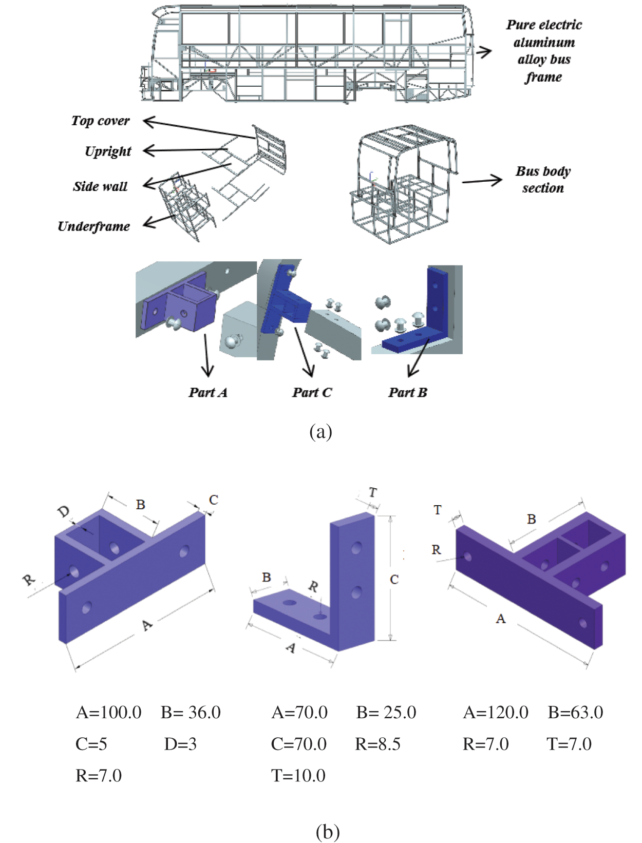
Figure 1: Body section and connecting structures: (a) Connection structure in the bus frame; (b) Initial parameters of connector parts (mm)
The primary objective is to determine the external shapes and combination characteristics of the aluminum bus frame’s internal connectors. Part A and Part C form a nested structure firmly riveted to the aluminum frame, while Part B adheres to the aluminum frame’s surface, secured by rivets. The original design parameters of these three connectors are illustrated in the diagram. Crucially, the interaction between the connectors and the frame generates a symmetrical “T” or “ cross” connection structure. This symmetry is evident in both the structure and deformation patterns, forming the fundamental premise for optimizing symmetrical parameters in the connection structure.
To further analyze the connection structure of the all-aluminum pure electric bus frame, we constructed a “cross” shaped connection structure. As depicted in Fig. 2, the three different connectors shown in the diagram form a “cross” assembly with the frame using rivets. They all exhibit symmetrical structures. When an all-aluminum bus encounters accidents like rollovers, where the bus’s side frame collapses, aside from the frame itself, parts such as the body paneling and windows also experience ground impact. The connection structure of the vehicle body also undergoes ground impact pressure, with most of the forces on the connection structure approximating perpendicular to the structural surface. Hence, we fabricated a “cross” structure composed of the aluminum bus frame and its connection structure, simulating vertical force deformation via three-point bending tests.
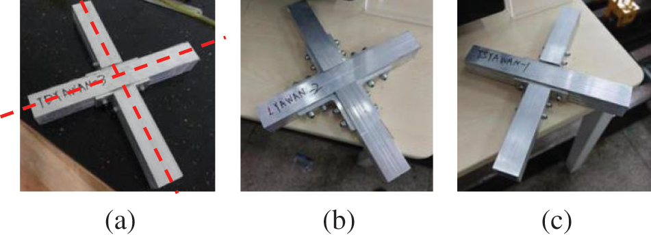
Figure 2: Test samples of connectors: (a) Part A (b) Part B (c) Part C
Utilizing the robust MTS-30 kN testing apparatus, meticulously designed setups for the three-point bending tests were arranged, as illustrated in Figs. 3a–3b. The experimental setup was carefully calibrated to ensure alignment between the fixtures and the sample’s central axis, with a standard fixture distance of 250 millimeters. Throughout the entire experiment, the descent rate of the indenter remained steady at 1 millimeter per minute [14]. This controlled pace ensured the precise data collection associated with the force exerted on each sample. In terms of data acquisition, dedicated force sensors based on strain gauges were sensibly integrated into the load application device. Notably, the test execution was meticulously planned, immediately ceasing once the test curve transitioned into a plateau phase. Each type of connection underwent three repeated tests, enhancing the robustness of the experimental data and affirming the reliability of the test results.
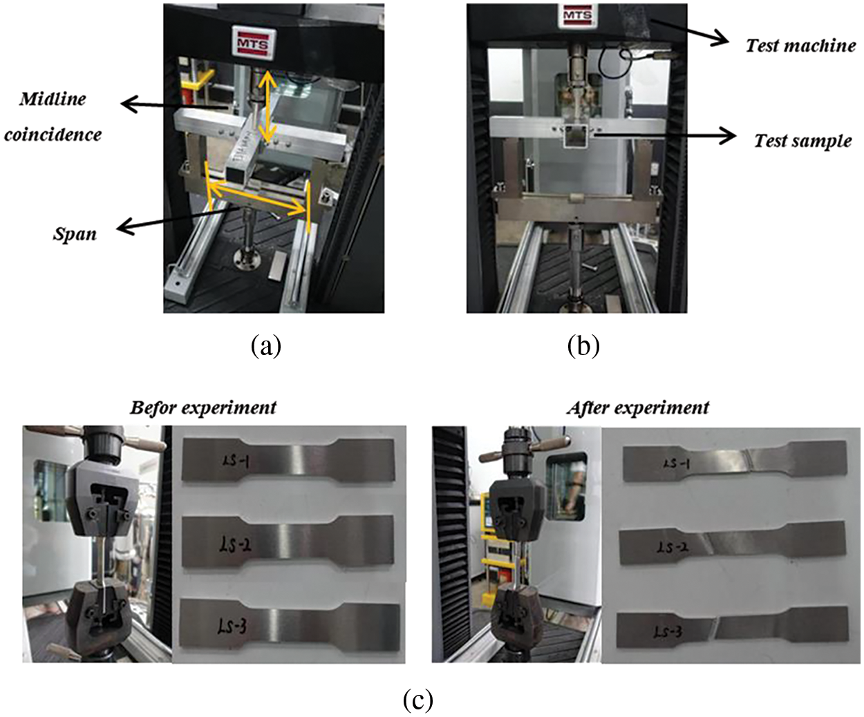
Figure 3: Commissioning of test equipments: (a) Fixture debugging (b) Rate debugging (c) Material tests
Additionally, we conducted material tests on this aluminum alloy to provide material curve data for subsequent simulation models. The body material primarily consisted of 6082-T6 aluminum alloy. To obtain accurate mechanical performance data of the material, we conducted tensile tests on the aluminum alloy in accordance with the “GBT228.1-2010-Methods for Tensile Testing of Metals at Room Temperature.” The resulting data was processed to derive true stress-strain curves. Sample dimensions were manufactured in accordance with the national standard, and the physical samples are depicted in the Fig. 3c. The samples were labeled as LS-1, LS-2, and LS-3.
We utilized the MTS-30 testing machine for the tensile experiments on these samples. The MTS-30 universal testing machine is capable of conducting tests according to national and various international standards, providing test data, and automatically extracting test parameters. The testing equipment included fixtures for gripping the tensile samples and sensors for recording displacement and force data. Under room temperature conditions, the samples were initially secured onto the apparatus using fixtures. The longitudinal strain rate of the material was set to 1 mm/min. Following the completion of the tests, force and displacement data received by the sensors were processed to derive true stress-strain data. We conducted three repetitions of the experiments, calculated the averages, resulting in the curve depicted in the Fig. 4a, and computed the associated mechanical parameters.
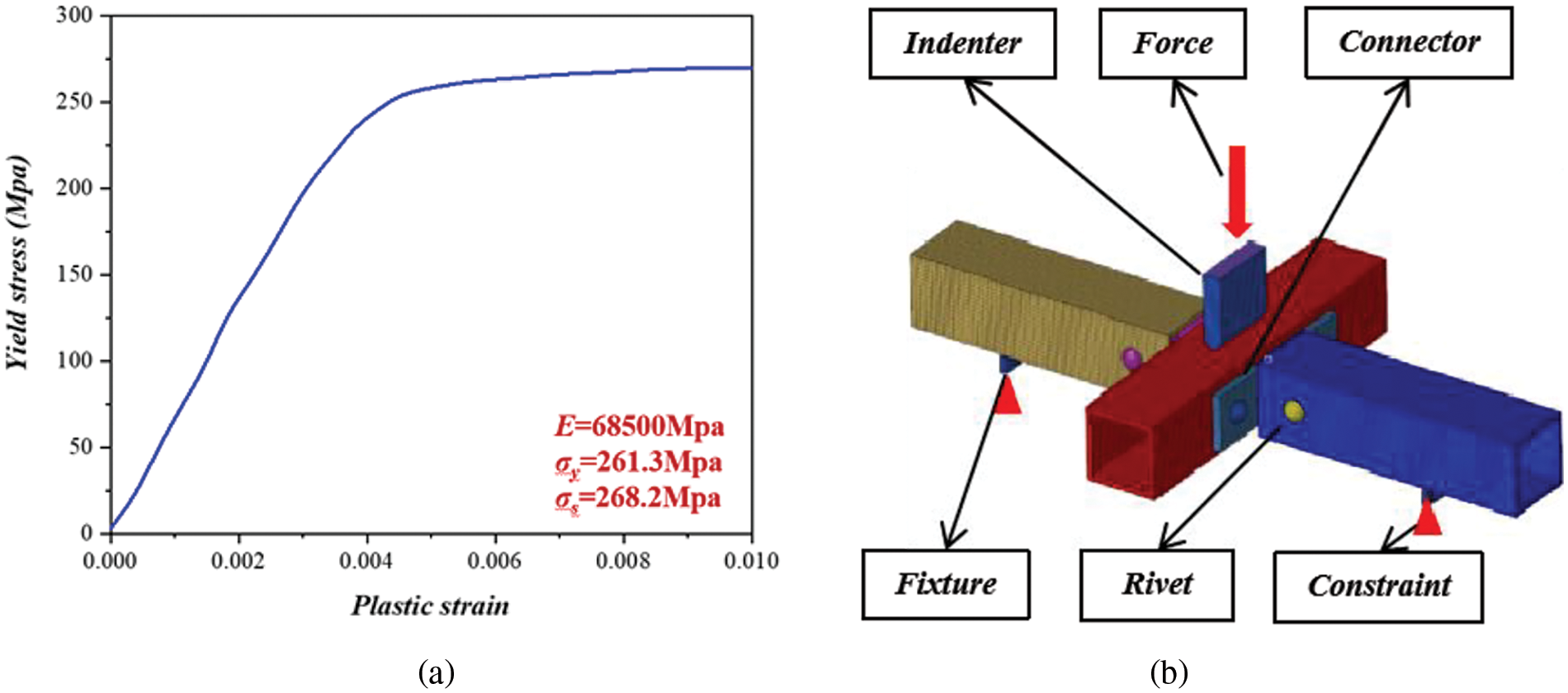
Figure 4: (a) True stress-strain curves of the material. (b) The finite element model of connector structures
2.3 Finite Element Simulation Analysis and Verification
After conducting the three-point bending experiments and material tests on the aluminum alloy, finite element simulation was employed to verify and analyze the three-point bending behavior of the aluminum alloy connection structure, as shown in Fig. 4b. The material properties required for the simulation were derived from the tensile tests performed on the 6082-T6 aluminum alloy material. In the LS-DYNA software, the piecewise linear plasticity model (MAT_24) was selected to define the equivalent materials of the connectors and the frame. For the anvils and fixtures, a rigid material model (MATL_20) was judiciously employed. To ensure the simulation’s accuracy, systematic constraints were applied to all degrees of freedom of the fixtures. Additionally, a detailed description of contact interactions was conducted through a surface-to-surface contact approach, with a static friction coefficient of 0.4 and a dynamic friction coefficient of 0.25 [15].
The results of the three-point bending simulation of the aluminum alloy electric bus connection structure, compared to experimental deformations, are shown in Fig. 5. The stress gradually increases from blue to red in the figure. Utilizing the inherent symmetry of the connector components, a quarter of the deformed results were chosen for comparative analysis. Remarkable similarities between the experimental and simulated results were observed, highlighting the effectiveness of the simulation framework. The simulation aptly captured the intricate deformation patterns exhibited during the three-point bending test, reflecting varying degrees of bending and separation among different connector components. The plastic hinges formed between the connector walls and square pipes played a significant role in the mechanical response. Furthermore, the simulation accurately depicted the interactions between rivets and the connection structure, revealing deformations occurring at the lower part of the rivet hole due to shear stresses [16,17].
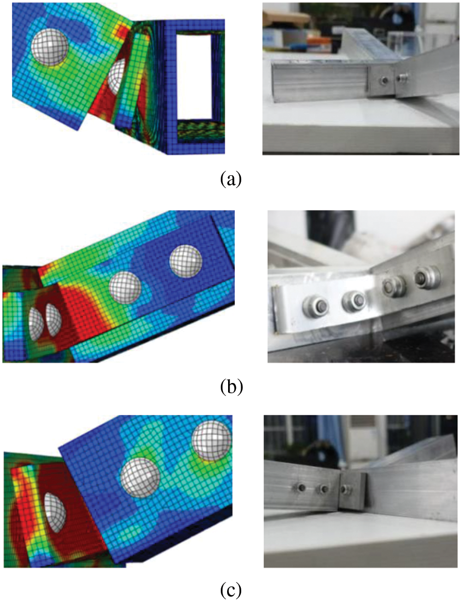
Figure 5: Comparison of cross member stress results: (a) Part A (b) Part B (c) Part C
To further compare and analyze the experimental and simulation results, the force-displacement curves for the anvils were plotted. As depicted in Fig. 6, the simulated curve closely matched the experimental curve, both demonstrating an elastic-plastic-platform phase. The simulation results tended to extend the elastic phase of the connectors, resulting in a relatively larger plastic region in the force-displacement curve. This approach ensured a rigorous and detailed characterization of the material’s behavior under loading conditions.
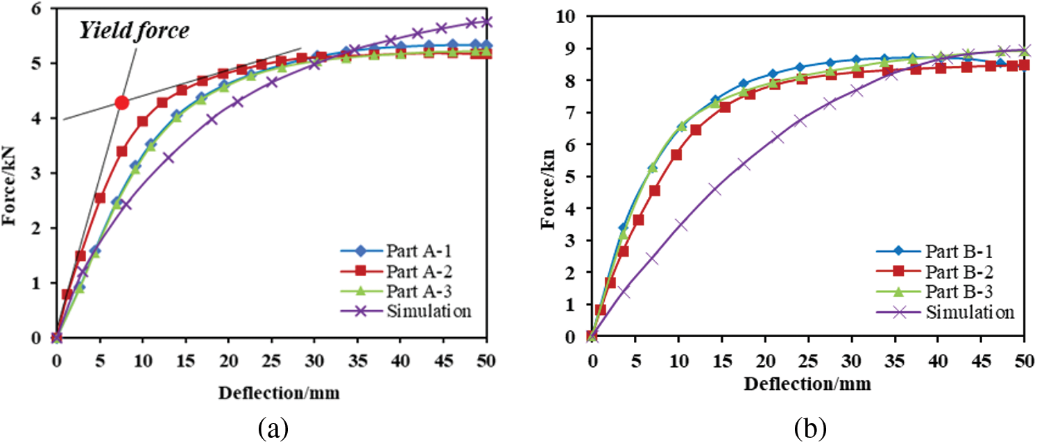
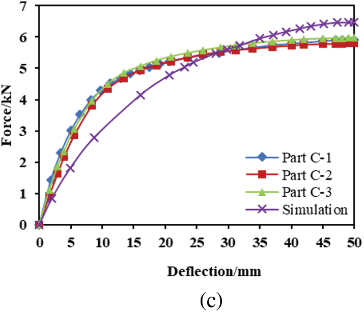
Figure 6: Comparison of test and simulation curves: (a) Part A (b) Part B (c) Part C
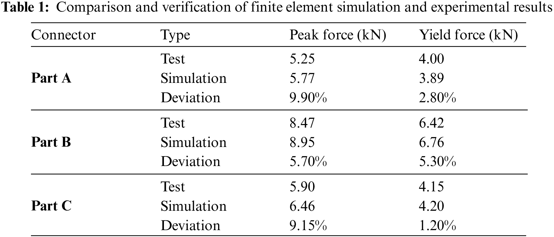
We validated the accuracy of the simulation through two key metrics: yield force and peak force, which represents the maximum force on the anvils. The yield force was precisely defined as the intersection of the tangent line between the elastic and plastic stages on the force-displacement curve, even when the load descent was barely perceptible [16,17]. The final comparative results are presented in Table 1, where the error rate between the simulated and experimental results was below 10%, effectively demonstrating the accuracy of the finite element simulation of the three-point bending behavior of the aluminum alloy electric bus connection structure.
2.4 Analysis of Stress Distribution and Deformation Modes
As illustrated in Fig. 7, examining the deformation and stress distribution across various degrees of deformation for each connector, where the transition from blue to red represents a gradual increase in stress, reveals a consistent pattern of stress transmission across all three connector types. This pattern involves stress propagation from the connector’s corner to its base and further extension to the upper part.
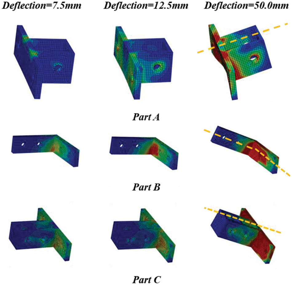
Figure 7: Stress cloud diagram of connectors for different deflections
Notably, Part A and Part C exhibit strict symmetry in both deformation and stress distribution throughout the loading sequence. Stress convergence is symmetrically observed at the corners where the upper part interfaces with the base. Interestingly, Part B slightly deviates from this symmetry, with quicker stress concentration on its lower side compared to the upper side. However, as deformation progresses, this discrepancy diminishes, and stress distribution in Part B tends toward greater symmetry.
Additionally, a distinct trend emerges where the base of all connectors bears the predominant pressure during stress evolution. Intriguingly, instances of bending and detachment are noticed between the base of the connecting piece and the square tube. Furthermore, there is a minor degree of distortion becoming evident in the lower portion of the rivet hole. The stress concentration notably emerges due to Part B’s narrower width and the inherent simplicity of its upper structure.
The research outlined in this paper was conducted leveraging a spectrum of software platforms to ensure comprehensive analysis and modeling. Catia served as the tool for parametric modeling, facilitating the creation of flexible designs. The fusion of Hypermesh and Abaqus platforms allowed for robust finite element modeling and rigorous simulation calculations.
Incorporating sophisticated methodologies, OLHD, RBF neural network approximation modeling, and multi-objective optimization were executed proficiently through the utilization of Isight software. This software enabled the systematic execution of these complex tasks, ensuring the precision and efficiency required for these intricate processes.
Furthermore, language refinement and enhancement were achieved through the aid of Deepl and ChatGPT. These tools played a pivotal role in translation tasks, embellishing language nuances, and refining the content to meet scholarly standards. Their assistance contributed significantly to the linguistic precision and readability of the paper.
3 Multi-Objective Collaborative Optimization of Connectors
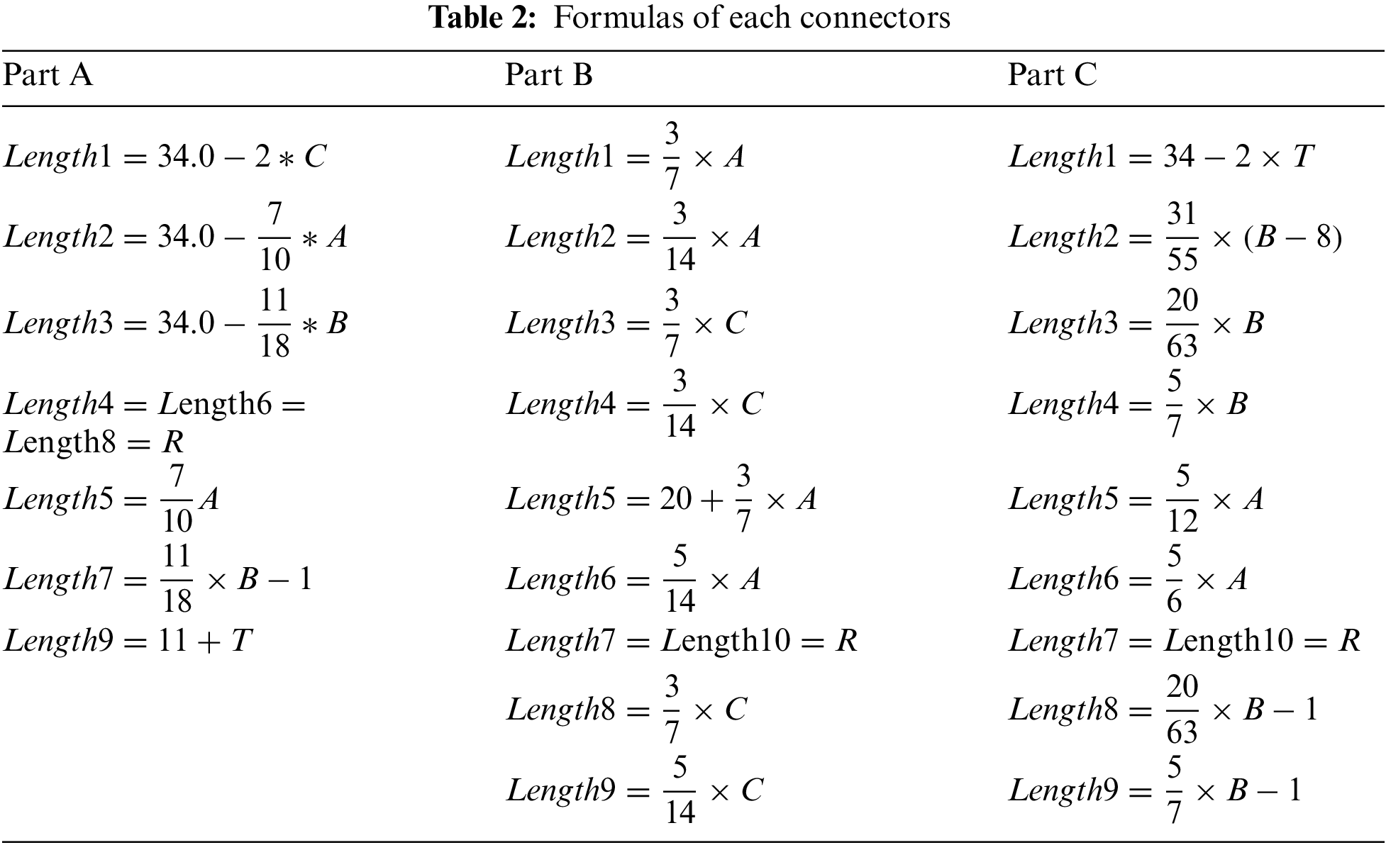
To establish accurate approximation models, a considerable number of sample points are required. Undertaking a complete remodelling would consume a substantial amount of time. Hence, this paper applies a parametric modeling method [18]. It involves interlinking various parameters within components using functional relationships. When the primary parameters of a component undergo changes, the corresponding structural attributes linked by these functional dependencies also undergo modifications [19]. The significance of this approach lies in its ability to swiftly influence changes among multiple variables, eliminating the need for repetitive modeling work and facilitating the establishment of automated optimization processes. Furthermore, certain design parameters of the connectors exhibit inherent symmetry. As a result, some parameters only require defining unilateral functional relationships, culminating in the completion of the final three-point bending modeling of the aluminum alloy bus frame connectors using a mirroring technique. The specific design parameter definitions and functional relationships are depicted in Fig. 8 and Table 2. The principal variables in the table represent the connector design variables optimized in this study [20].
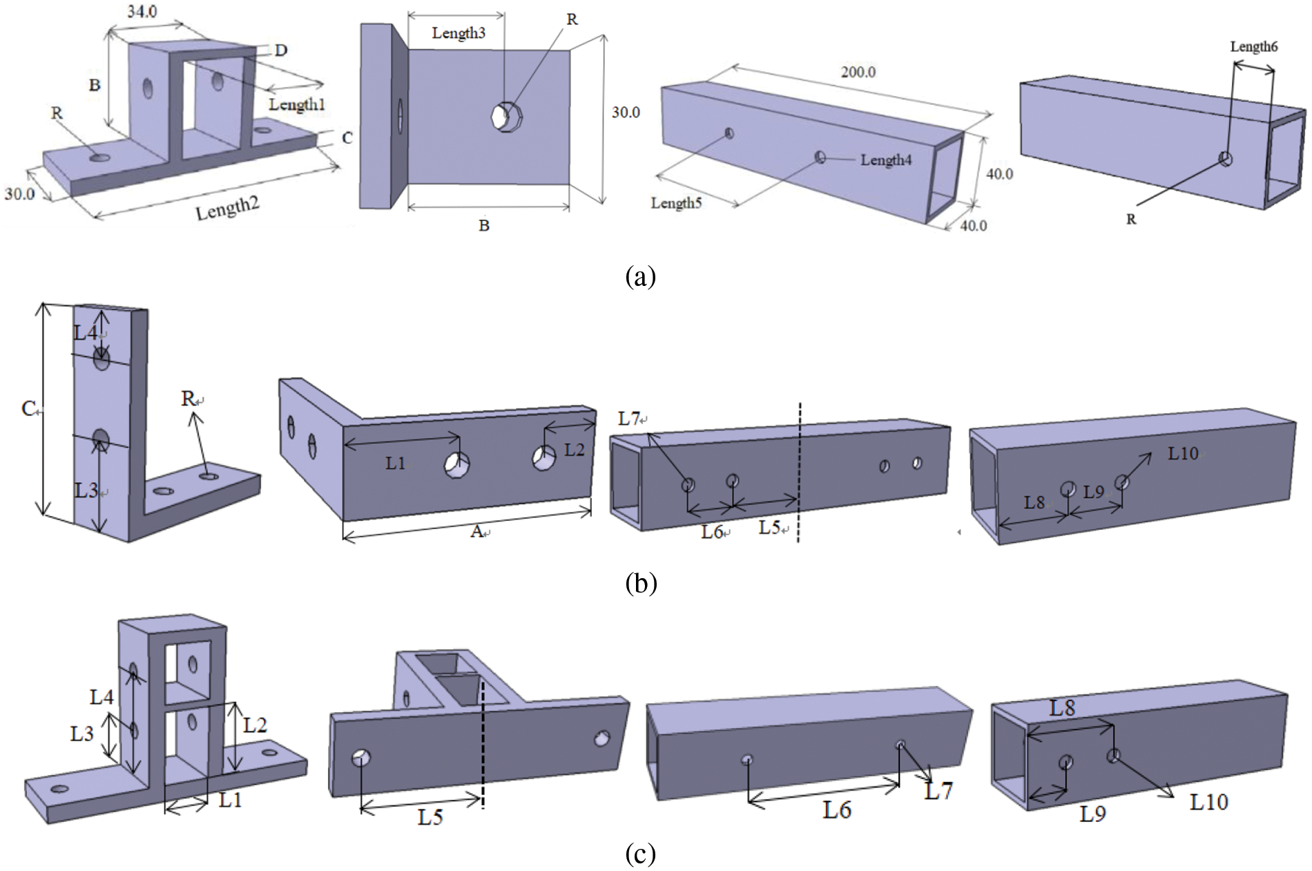
Figure 8: Parametric modeling of each connector: (a) Part A (b) Part B (c) Part C
3.2 Building Radial Basis Function (RBF) Neural Network Approximate Model
The objective of this study is to optimize the design parameters of connectors to enhance the energy absorption and lightweight characteristics of the aluminum alloy bus frame’s ‘cross’-shaped connecting components. Previously, we validated the accuracy of the finite element model through quasi-static simulations and experiments. Next, we employed a sampling method to establish an approximation model between design parameters and optimization objectives. In this step, in our earlier work, we utilized OLHD to search for sample points within a wide range of aluminum alloy connector design parameters. Renowned for its uniformity, spatial characteristics, minimized sampling overhead, and exceptional precision, OLHD served as the ideal framework for random sampling [21].
To efficiently and accurately identify the design parameters for collaborative optimization required in this paper, we proceeded to establish RBF approximation models for the three-point impact bending of the aluminum alloy bus frame’s three connecting components. Accurate approximation models can replace the actual production testing process, thereby saving costs and improving efficiency. However, constructing accurate RBF approximation models does not depend solely on the breadth of the sample point range or the number of sample points [22].
During the modeling process using Isight software, we found that although modeling within approximately ±10% of the original design parameters could establish high approximation models, it imposed limitations on the optimization design range. Therefore, we established approximation models for Part A within a range of approximately ±15% of the original design parameters, and for Part B and Part C within a range of approximately ±20% of the original design parameters. This approach not only expanded the design scope but also maintained a high level of accuracy.
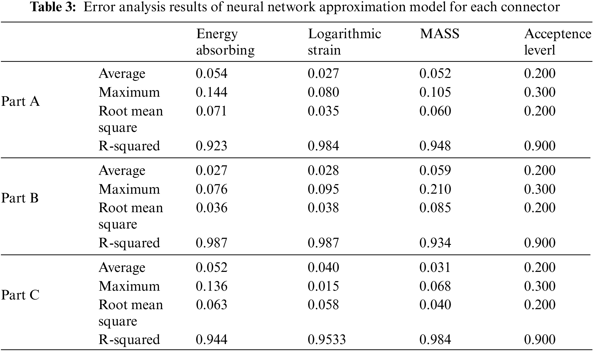
Finally, we used RBF approximation models to establish models for the three types of connectors, with partial images shown in Fig. 9. From the figures, it is apparent that the relationship between the energy absorption objective and the design parameters is nonlinear. Part A employed 62 sample points to establish its approximation model, Part B used 144 sample points, and Part C used 129 sample points. Each neural network approximation model underwent cross-validation using 10 sample points. Their respective accuracies are detailed in Table 3.
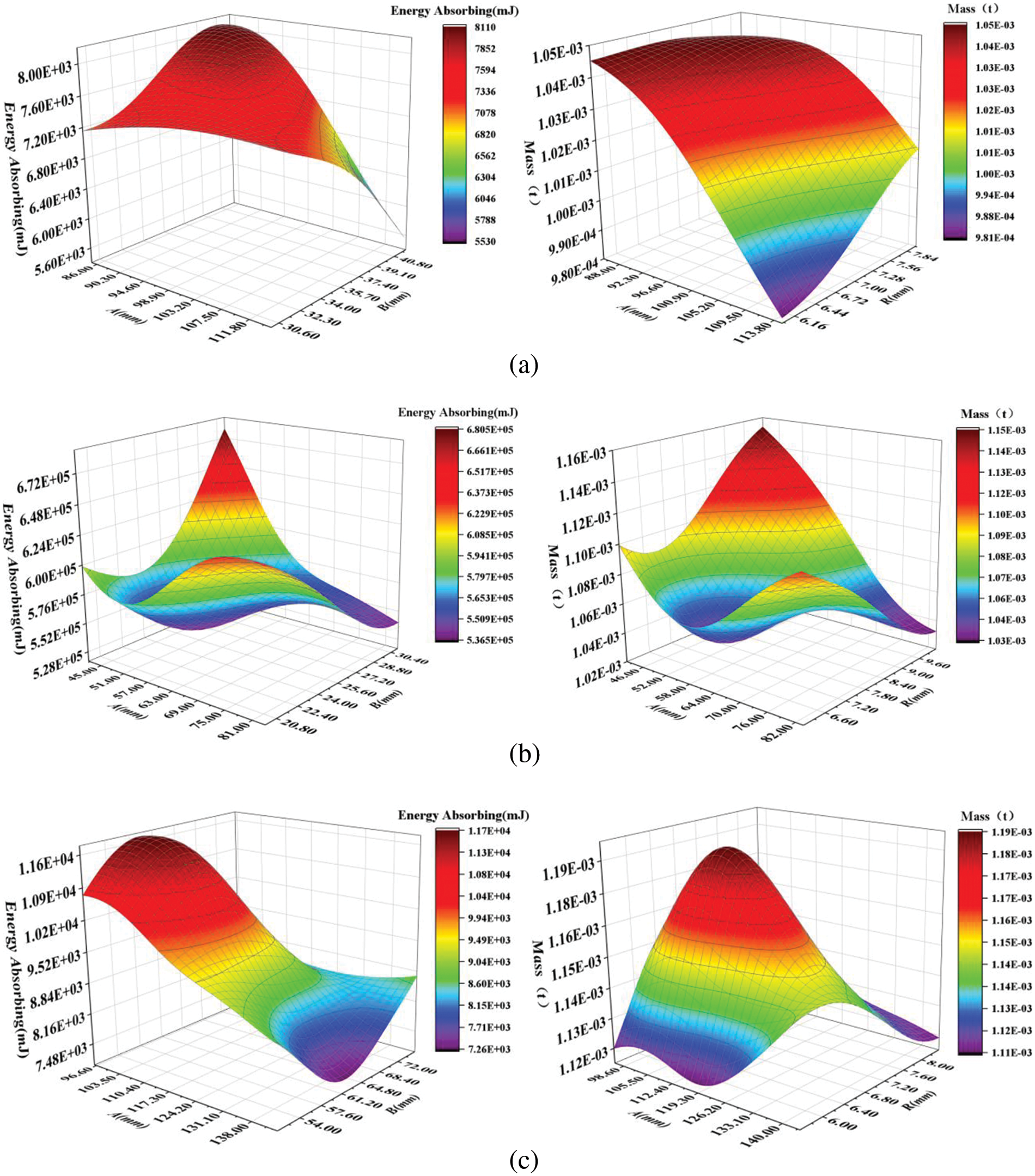
Figure 9: Partial approximation model of design parameters of each connector corresponding to optimization objective: (a) Part A; (b) Part B; (c) Part C
3.3 Multi-Objective Collaborative Optimization Solution
Combined with the actual situation, we determined the optimization objectives and the scope of the optimization design [23]. The multi-objective optimization publicity of Part A, Part B and Part C is as follows (1)–(3). In addition, we set the three objectives of energy absorption (EA), mass (M) and logarithmic strain (LE) to be greater than zero in the optimization process [24].
Additionally, previous research typically focused on energy absorption and mass as primary objectives. However, this study integrates deformation resistance as a target, which significantly contributes to the durability of the frame. Despite this inclusion, the three objectives maintain a certain precedence, with the emphasis of this study leaning towards energy absorption and mass. We assigned weights of 1.0, 1.0, and 0.5 to energy absorption, mass, and strain, respectively. Numerous studies have explored various multi-objective optimization algorithms [25–27]. Commonly employed algorithms for component design optimization include. This paper employed three methods, namely, AMGA, MOPSO and NSGA2, for multi-objective optimization. These methods encompass both traditional optimization algorithms (AMGA and NSGA2) as well as more frequently used methods in recent years (MOPSO) [28]. The parameters for each method were configured as follows:
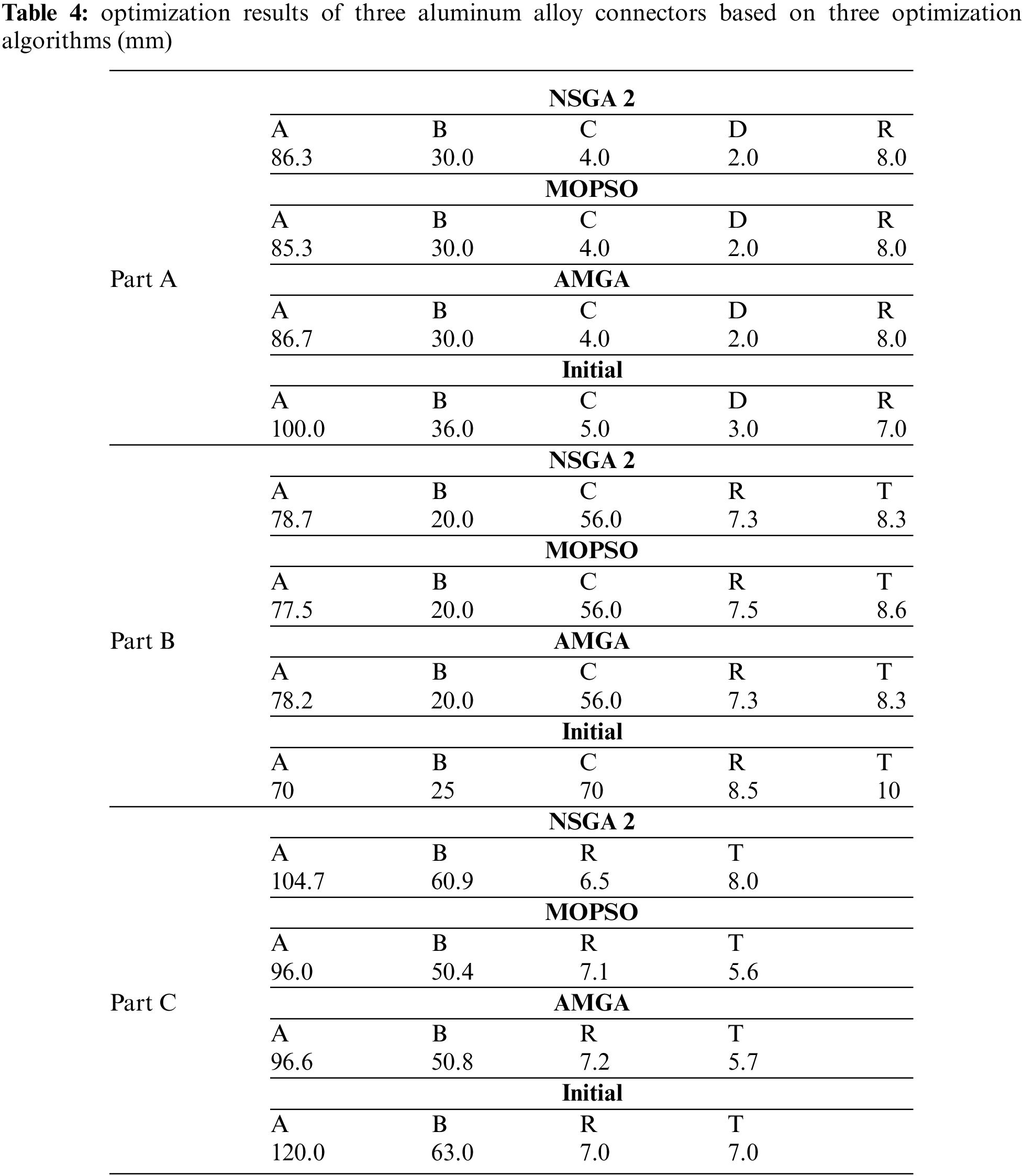
After multiple iterations, each method exhibited strong convergence and generated the Pareto front. The Pareto fronts generated by each multi-objective optimization algorithm for individual components are illustrated in Fig. 10. From the graphs, it is evident that each method demonstrates a relatively smooth Pareto surface. The points on the Pareto surface achieve commendable objectives. However, owing to the previously assigned weights for each objective, the Pareto front attained optimal values. The specific numerical values are detailed in Table 4.
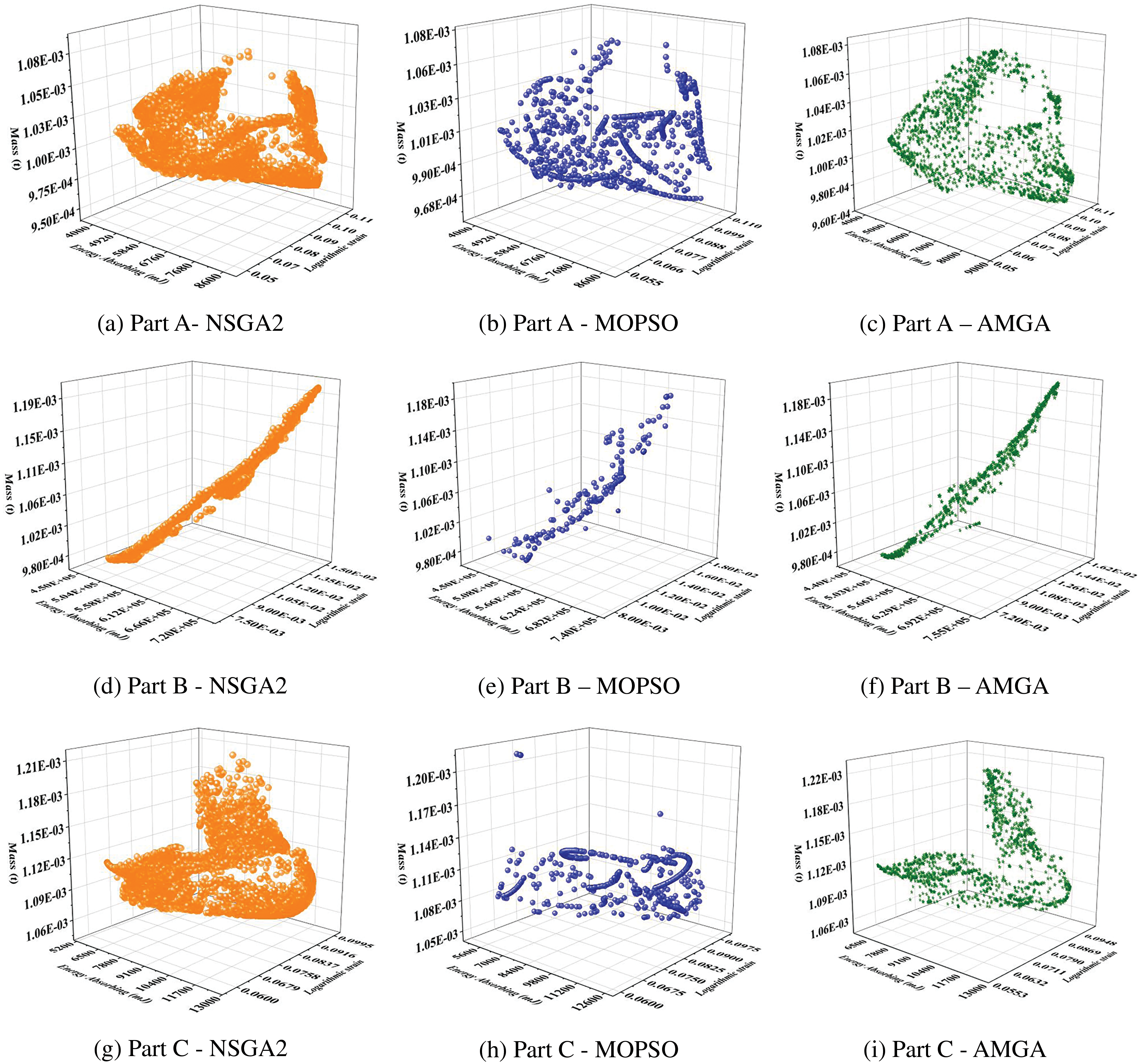
Figure 10: The three connectors correspond to the Pareto front of the three optimization algorithms: (a)–(c) is the Pareto front of Part A (d)–(f) is the Pareto front of Part B (g)–(i) is the Pareto front of Part C
We compared the simulation results of the three components’ various optimized designs to identify the best design solution. To assess each optimization against the original design, we simulated the impact force the aluminum electric bus might experience in a rollover accident. The velocity of the pressure head was set at 5 m/s, and a three-point bending impact simulation was performed to compute each optimization scenario. The final results are presented in Table 5. The maximum strain in the table reflects the deformation of the connecting components, while mass and energy absorption represent individual connecting component responses.
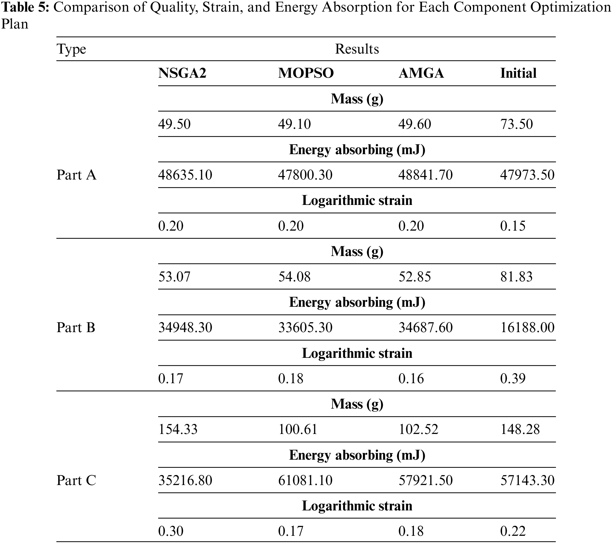
The results reveal that after the optimization of Part A via the three strategies, the mass decreased from 73.50 g to a range between 49.10–49.60 g, indicating a reduction of approximately 32% in mass. The optimization designs generated by NSGA2 and AMGA methods improved the energy absorption of Part A. However, none of these three optimization algorithms were able to reduce the deformation of the connecting components while reducing mass and increasing energy absorption. Hence, the selection of an optimization plan will require a balance between these actual requirements. Nevertheless, under the collaborative optimization objective, the solutions provided by NSGA2 and AMGA also achieved this goal.
The three optimization solutions for Part B performed better compared to the previous design. The mass decreased from 81.83 g to a range between 52.85–54.08 g, representing a reduction of approximately 35% in mass. There was a substantial increase in energy absorption, and strain was significantly reduced. However, it is also evident that the optimization solution provided by AMGA is more suitable for Part B than the other two.
The superiority and inferiority among the three optimization solutions for Part C are apparent. The optimization solution generated by the NSGA2 method did not meet the collaborative optimization goal. However, the solutions produced by MOPSO and AMGA methods both performed well. They reduced the mass of Part A from 148.28 to 100.61 g and 102.52 g, respectively, decreased strain by 23% and 18%, and notably increased energy absorption. However, it is evident that the MOPSO solution performed best in various optimization goals.
In this study, we optimized the frame connectors of aluminum pure electric buses, enhancing their energy absorption, reducing mass, and improving their deformation resistance. Previous literature and practical investigations highlighted a risk of increased deformability in aluminum electric bus frames due to the specific characteristics of aluminum alloys. This risk could potentially impact the vehicle’s durability despite achieving environmental goals. Reviewing the literature and drawing on previous research and experience, we hypothesized that enhancing the mechanical properties and lightweight nature of the aluminum frame connectors could bolster the vehicle’s durability while easing energy demands. Consequently, we meticulously selected three commonly used aluminum electric bus body connectors. Based on their arrangement within the frame, we designed a simplified ‘cross’ shaped connecting component. We also examined the impact force directions on the aluminum bus body in side collisions and rollovers, consequently designing a three-point bending impact model.
To establish and validate this finite element model’s accuracy, we conducted tensile tests on 6082-T6 aluminum alloy materials according to standards, obtaining the corresponding material curves. These curves were incorporated into the finite element model. Manufacturing these connectors using the specified material, we performed quasi-static three-point bending experiments on the aluminum bus frame connectors. We verified the finite element models under similar conditions using two indicators: peak force and yield force. The error was within 10%, affirming the model’s accuracy.
The goal of this study was to enhance the lightweight, energy absorption, and deformation resistance of the connectors. For efficient optimization, we employed OLHD and RBF Approximation to establish approximate models for the design parameters and optimization objectives of the three aluminum alloy connecting components. Approximately 150–200 sample points were taken for each component. Through the selection and modeling process of Isight software, we achieved high-precision RBF approximations with R-Squared values exceeding 0.9. However, manually creating hundreds of models would be time-consuming. Hence, we utilized parameterized modeling, linking primary design parameters with passive parameters using function relationships. Consequently, modifying primary design variables as per sample point requirements could intelligently yield the corresponding model output.
Following the development of high-precision RBF approximate models for the three aluminum frame connectors, we aimed to generate suitable optimization solutions to reconcile the three natural conflicting objectives. We utilized three multi-objective optimization methods, namely NSGA2, MOPSO, and AMGA. Ultimately, each connector generated three optimization solutions. To validate these solutions, we referred to the landing speed in a rollover scenario, applying a bending speed of 5 m/s to the simulation models. After computation, NSGA2 and AMGA enhanced the energy absorption of Part A while reducing its mass by approximately 32%. The AMGA solution significantly increased Part B’s energy absorption, reducing its mass by around 35%. The MOPSO solution reduced Part C’s strain by 23%, decreased its mass from 148.28 g to 100.61, and notably increased its energy absorption.
Upon holistic evaluation, the enhancement across mechanical performance and lightweight design of connectors between initial and optimized models attests to the relevance of the proposed methodology. This versatile hybrid approach, particularly effective for nonlinear, large deformation, and multi-objective optimization challenges, holds significant promise for symmetrical lightweight material components.
Acknowledgement: During the preparation of this work the authors used Chat Generative Pre-trained Transformer (ChatGpt) in order to improve language and readability. After using this tool, the authors reviewed and edited the content as needed and take full responsibility for the content of the publication. ChatGPT is a new natural language processing tool powered by artificial intelligence technology from OpenAI, an American artificial intelligence research lab.
Funding Statement: The authors are grateful to the National Natural Science Foundation of China (Grant Number 52075553), and the Postgraduate Research and Innovation Project of Central South University (School-Enterprise Association) (Grant Number 2021XQLH014).
Author Contributions: The authors confirm contribution to the paper as follows: study conception and design: Wenjun Zhou, Qian Peng; data collection: Qiang Xiao; analysis and interpretation of results: Wenjun Zhou, Yong Peng, Mingzhi Yang; draft manuscript preparation: Yong Peng, Kui Wang. All authors reviewed the results and approved the final version of the manuscript.
Availability of Data and Materials: The data that support the findings of this study are available from the first author upon reasonable request.
Conflicts of Interest: The authors declare that they have no conflicts of interest to report regarding the present study.
References
1. Cho, Y., Kim, S., Kim, T. (2014). Structural behaviors and curling influence of single shear bolted connections with aluminum alloys (7075-T6). International Journal of Precision Engineering and Manufacturing, 15(1), 183–187. [Google Scholar]
2. Tinl, N., Menzemer, C. C., Manigandan, K., Srivatsan, T. S. (2013). The bearing strength and fracture behavior of bolted connections in two aluminum alloys. Journal of Materials Engineering and Performance, 22(11), 3430–3438. [Google Scholar]
3. Cho, Y., Kim, T. (2015). Ultimate strength and shear-lag effect of aluminum alloy (6063-T5) bolted angle connections. International Journal of Precision Engineering and Manufacturing, 16(7), 1681–1684. [Google Scholar]
4. Liang, C. C., Le, G. N. (2010). Optimization of bus rollover strength by consideration of the energy absorption ability. International Journal of Automotive Technology, 11(2), 173–185. [Google Scholar]
5. Zhang, Y., Wang, Y., Li, B., Zhi, X., Lu, C. et al. (2022). Structural performance of novel aluminium alloy gusset joints for connecting four I-section beam members. Journal of Building Engineering, 53, 104547. [Google Scholar]
6. Xu, S., Li, W., Li, L., Li, T., Ma, C. (2022). Crashworthiness design and multi-objective optimization for bio-inspired hierarchical thin-walled structures. Computer Modeling in Engineering & Sciences, 131(2), 929–947. https://doi.org/10.32604/cmes.2022.018964 [Google Scholar] [PubMed] [CrossRef]
7. Wang, D., Xie, C., Liu, Y., Xu, W., Chen, Q. (2020). Multi-objective collaborative optimization for the lightweight design of an electric bus body frame. Automotive Innovation, 3(3), 250–259. [Google Scholar]
8. Zhong, W., Su, R., Gui, L., Fan, Z. (2016). Multi-objective topology and sizing optimization of bus body frame. Structural and Multidisciplinary Optimization, 54(3), 701–714. [Google Scholar]
9. Wang, D., Jiang, R., Wu, Y. (2016). A hybrid method of modified NSGA-II and TOPSIS for lightweight design of parameterized passenger car sub-frame. Journal of Mechanical Science and Technology, 30(11), 4909–4917. [Google Scholar]
10. Gao, D., Zhang, N., Feng, J. (2017). Multi-objective optimization of crashworthiness for mini-bus body structures. Advances in Mechanical Engineering, 9(7). https://doi.org/10.1177/1687814017711854 [Google Scholar] [CrossRef]
11. Chen, G. (2012). Multi-objective optimization method based on agent model and its application to car body design (Ph.D. Thesis). Hunan University, Changsha, China. [Google Scholar]
12. Yin, A., Xu, J., Cao, C. (2015). Multi-objective optimization of electric vehicle body in white based on GRSM. Journal of Hefei University of Technology (Natural Science Edition), 38(12), 1607–1611+1616. [Google Scholar]
13. Nguyen, T. C. (2019). Research to evaluate the quality of passenger bus body frame, assuring the passive safety in the design process. Applied Mechanics and Materials, 889, 440–447. [Google Scholar]
14. Kristoffersen, M., Langseth, M., Børvik, T. (2018). Combined three-point bending and axial tension of pressurised and unpressurised X65 offshore steel pipes–experiments and simulations. Marine Structures, 61, 560–577. [Google Scholar]
15. Zhao, J., Yu, C. (2019). Experimental study and numerical simulation of G550 high strength cold-formed steel Z-section members under pure bending and moment gradient. International Journal of Steel Structures, 19(2), 366–380. [Google Scholar]
16. Li, X., Yin, Y., Zhu, X., Wang, R., Li, T. et al. (2023). Performance of hollow and aluminum foam-filled multi-cell thin-walled aluminum alloy tubes (6063-T5) under axial impact. Structures, 47, 1803–1821. [Google Scholar]
17. Banoth, S., Suresh Babu, V., Raghavendra, G., Hari Shankar, P. (2023). Study of various types of aluminium alloy grade series and their effect on mechanical performance. Materials Today: Proceedings. https://doi.org/10.1016/j.matpr.2023.04.635 [Google Scholar] [CrossRef]
18. Wang, D., Cai, K. (2018). Optimizing the static-dynamic performance of the body-in-white using a modified non-dominated sorting genetic algorithm coupled with grey relational analysis. Engineering Optimization, 50(4), 615–633. [Google Scholar]
19. Zuo, W., Chen, M. T., Chen, Y., Zhao, O., Cheng, B. et al. (2023). Additive manufacturing oriented parametric topology optimization design and numerical analysis of steel joints in gridshell structures. Thin-Walled Structures, 188, 110817. [Google Scholar]
20. Simpson, T. W., Mauery, T. M., Korte, J., Mistree, F. (2001). Kriging models for global approximation in simulation-based multidisciplinary design optimization. AIAA Journal, 39, 2233–2241. [Google Scholar]
21. Shojaeefard, M. H., Khalkhali, A., Firouzgan, A. (2016). Multi-objective optimization of a natural aspirated three-cylinder spark ignition engine using modified non-dominated sorting genetic algorithm and multicriteria decision making. Journal of Renewable and Sustainable Energy, 8(2), 025705. [Google Scholar]
22. Meng, Z., Qian, Q., Xu, M., Yu, B., Yıldız, A. R. et al. (2023). PINN-FORM: A new physics-informed neural network for reliability analysis with partial differential equation. Computer Methods in Applied Mechanics and Engineering, 414, 116172. [Google Scholar]
23. Meng, Z., Yıldız, B. S., Li, G., Zhong, C., Mirjalili, S. et al. (2023). Application of state-of-the-art multiobjective metaheuristic algorithms in reliability-based design optimization: A comparative study. Structural and Multidisciplinary Optimization, 66(8), 191. [Google Scholar]
24. Bagheri, M. R., Mosayebi, M., Mahdian, A., Keshavarzi, A. (2018). Weighted sum Pareto optimization of a three dimensional passenger vehicle suspension model using NSGA-II for ride comfort and ride safety. Smart Structures and Systems, 22(4), 469–479. [Google Scholar]
25. Kookalani, S., Cheng, B., Xiang, S. (2021). Shape optimization of GFRP elastic gridshells by the weighted Lagrange ε-twin support vector machine and multi-objective particle swarm optimization algorithm considering structural weight. Structures, 33, 2066–2084. [Google Scholar]
26. Okasha, N. M., Alzo’ubi, A. K., Mughieda, O., Kewalramani, M., Almasri, A. H. (2024). A near-optimum multi-objective optimization approach for structural design. Ain Shams Engineering Journal, 15(2), 102388. [Google Scholar]
27. Cai, Y., Jelovica, J. (2023). Neural network-enabled discovery of mapping between variables and constraints for autonomous repair-based constraint handling in multi-objective structural optimization. Knowledge-Based Systems, 280, 111032. [Google Scholar]
28. Gkiotsalitis, K., Alesiani, F. (2018). Reliable bus dispatching times by coupling Monte Carlo evaluations with a Genetic Algorithm. 2018 21st Int. Conf. on Intelligent Transportation Systems (ITSC), pp. 926–932. Maui, HI, USA. [Google Scholar]
Cite This Article
 Copyright © 2024 The Author(s). Published by Tech Science Press.
This work is licensed under a Creative Commons Attribution 4.0 International License , which permits unrestricted use, distribution, and reproduction in any medium, provided the original work is properly cited.
 Downloads
 Citation Tools