
 Submit a Paper
 Propose a Special lssue
 Open Access
ARTICLE

Dynamic Response of a Nonlocal Multiferroic Laminated Composite with Interface Stress Imperfections
Department of Civil Engineering, National Yang Ming Chiao Tung University, Hsinchu, 30010, Taiwan
* Corresponding Author: Hsin-Yi Kuo. Email:
Computer Modeling in Engineering & Sciences 2025, 144(1), 841-872. https://doi.org/10.32604/cmes.2025.065452
Received 13 March 2025; Accepted 18 June 2025; Issue published 31 July 2025
 View Full Text
 Download PDF
Abstract
This study aims to investigate the propagation of harmonic waves in nonlocal magneto-electro-elastic (MEE) laminated composites with interface stress imperfections using an analytical approach. The pseudo-Stroh formulation and nonlocal theory proposed by Eringen were adopted to derive the propagator matrix for each layer. Both the propagator and interface matrices were formulated to determine the recursive fields. Subsequently, the dispersion equation was obtained by imposing traction-free and magneto-electric circuit open boundary conditions on the top and bottom surfaces of the plate. Dispersion curves, mode shapes, and natural frequencies were calculated for sandwich plates composed of BaTiO3 and CoFe2O4. Numerical simulations revealed that both interface stress and the nonlocal effect influenced the tuning of the dispersion curve and mode shape for the given layup. The nonlocal effect caused a significant decrease in the dispersion curves, particularly in the high-frequency regions. Additionally, compared to the nonlocal effect, the interface stress exerted a greater influence on the mode shapes. The generalized analytical framework developed in this study provides an effective tool for both the theoretical analysis and practical design of MEE composite laminates.Keywords
The ongoing trends of device miniaturization has driven significant interest in the magneto-electro-elastic (MEE) nanostructures comprising piezoelectric and piezomagnetic phases. The MEE heterostructures exhibit novel electrical, magnetic, and mechanical properties, offering promising applications in intelligent adaptive systems, including memory devices and energy harvesting [1,2]. Since MEE nanostructures exist at the nanoscale, their behavior and overall properties differ significantly from those of bulk composites. Long-range interatomic and intermolecular cohesive forces play a more significant role in determining the properties of MEE nanostructures [3]. Consequently, size effects must be accounted for in both theoretical and experimental studies [4,5]. While classical continuum mechanics remains a valuable tool, its scale-independent nature may lead to inaccurate results when analyzing nanostructures.
The nonlocal elasticity theory proposed by Eringen [6,7], which accounts for scale effects, offers a computationally efficient alternative to direct atomistic or molecular dynamics simulations [8]. For example, Wu and Li [9] effectively implemented this theory in free vibration analyses of embedded single-layered nanoplates and graphene sheets. Wu and Yu [10] investigated its application to nanobeams and carbon nanotubes (CNT), incorporating nonlocal effects. The application of the theory has been further extended to MEE plates [11–14], and MEE fibrous composites [15–17].
Dynamic responses of MEE composites, such as wave propagation and free vibration, have attracted significant research attention in recent years. Fundamental to the design process is determining natural frequencies and corresponding vibration modes-an analysis that has become a focal point in several studies. For example, Liu et al. [18] developed a dynamic analysis method for three-phase MEE structures using overlapping triangular finite elements. Jiang et al. [19] created a coupled MEE edge-based smoothed finite element method to evaluate the dynamic behavior of MEE solids. Kuo et al. [20] systematically compared wave propagation characteristics in MEE laminated composites with varying layering directions. Ly et al. [21] introduced a numerical approach for nonlinear analysis and smart damping control in functionally graded CNT reinforced MEE plate.
Most studies assume perfectly bonded interfaces between different phases-an idealized condition that may not reflect real-world scenarios. However, interfaces often exhibit imperfections due to cracking, dislocations, aging, or manufacturing defects. Additionally, these interfacial imperfections significantly affect magneto-electric coupling effects. Several studies have addressed interfacial imperfections in MEE composites, including [22–24] for static cases and [25,26] for dynamic cases.
Therefore, this study aims to investigate MEE laminates using the nonlocal theory proposed by Eringen, with a particular focus on extended interface stress-type contact condition. The paper is organized as follows. Section 2 presents the formulation of the multifield boundary-value problem, including considerations of extended interface stress imperfections. Section 3 presents the derivation of the field solutions for each homogeneous layer using the pseudo-Stroh formulation. A recursive framework that incorporates both propagation and interface matrices is developed to account for imperfect interface characteristics and determine exact solutions throughout the laminate. Section 4 discusses particular numerical cases analyzing the effect of the interface stress and nonlocal length parameters. Section 5 provides conclusions remarks.
2.1 Nonlocal Theory for MEE Materials
We consider a three-dimensional N−bonded orthotropic and rectangular MEE plate with nonlocal effect as shown in Fig. 1. A global Cartesian coordinate system

Figure 1: Geometry and coordinate system of an N-bonded orthotropic, nonlocal rectangular linearly MEE plate. The laminated plate is horizontally infinite but vertically finite in the y-direction with total thickness H. The jth layer is bonded by its lower interface
Following Pan and Waksmanski [13], the constitutive relations of a nonlocal linear anisotropic MEE within the context of nonlocal model proposed by Eringen can be expressed as
where
The infinitesimal strain
for which comma followed by lowercase subscript
For each individual plate, the equilibrium equations for the stress, electric displacement, and magnetic flux in the absence of body forces and electric sources are defined by
Here
3 Free Vibration Analysis of the MEE Laminate
3.1 Field Solutions for Each Nonlocal Plate
We consider the material is orthotropic symmetry. The polarization and magnetization directions are along the
Here
Assuming time-harmonic vibration motion, the field solutions are sought in the form of
where
Substituting Eqs. (4) and (5) into Eqs. (1) and (2), the nonlocal constitutive relation yields
where matrices
Furthermore, inserting Eq. (5) into the governing Eq. (3) leads to a quadratic eigenequation, as follows:
Finally, the above equation with the help of Eq. (6) can further be converted into the linear eigensystem of equations
Here
from the constitutive law (1).
Without the proportional position term
with
and
here
By eliminating the involved undetermined coefficients constants
where
is the propagation matrix of the
In order to complete the total field solutions, the remaining in-plane stress, electric displacement, and magnetic flux density are organized as follows:
Substituting the extended displacement expansion in Eq. (5) and Eq. (15) into the constitutive relation (1), additional relations between the associated expansion coefficients are derived as
3.2 Interface Stress-Type Imperfect Interface
To find the exact solutions, we need the interfacial conditions. We consider the extended interface stress interfacial conditions [30]:
where
where the interface matrix
Here
3.3 Recursive Field Solutions in the Laminate
Transferring the general field solution from the
where
Combining (11) and (21) and then substituting the result into (18) yields
where
Therefore, when transferring the solution from the
Here the propagator matrix
The prescribed boundary conditions on both bottom
By means of the above boundary conditions, the recursive field
yields the dispersion equation
4 Numerical Results and Discussion
To investigate the behavior of nonlocal effects and interface stresses, the proposed solution was applied to a sandwich plate composed of piezoelectric barium titanate (BaTiO3, BTO) and piezomagnetic cobalt ferrite (CoFe2O4, CFO). Two laminate configurations were examined: (1) a BTO/CFO/BTO layered structure and (2) a CFO/BTO/CFO layered structure. All three layers were assumed to have equal thickness, while the materials were transversely isotropic. The material properties used in the numerical analysis were as follows:
The imperfect interface was modeled as a thin interphase layer
where
here
where
For numerical analysis, the wave was assumed to propagate exclusively along the
Figs. 2 and 3 illustrate the dispersion curves for the first three Lamb wave modes of nonlocal BTO/CFO/BTO and CFO/BTO/CFO sandwich plates. The results showed that the dispersion curves for the classical case (i.e.,


Figure 2: Dispersion curves for Lamb waves in a BTO/CFO/BTO sandwich plate with different interface contacts: perfect contact, imperfect contact with the relative scaling parameter


Figure 3: Dispersion curves for Lamb waves in a CFO/BTO/CFO sandwich plate with different interface contacts: perfect contact, imperfect contact with the relative scaling parameter
Furthermore, the dispersion curves exhibited distinct discontinuities at specific wavenumber values
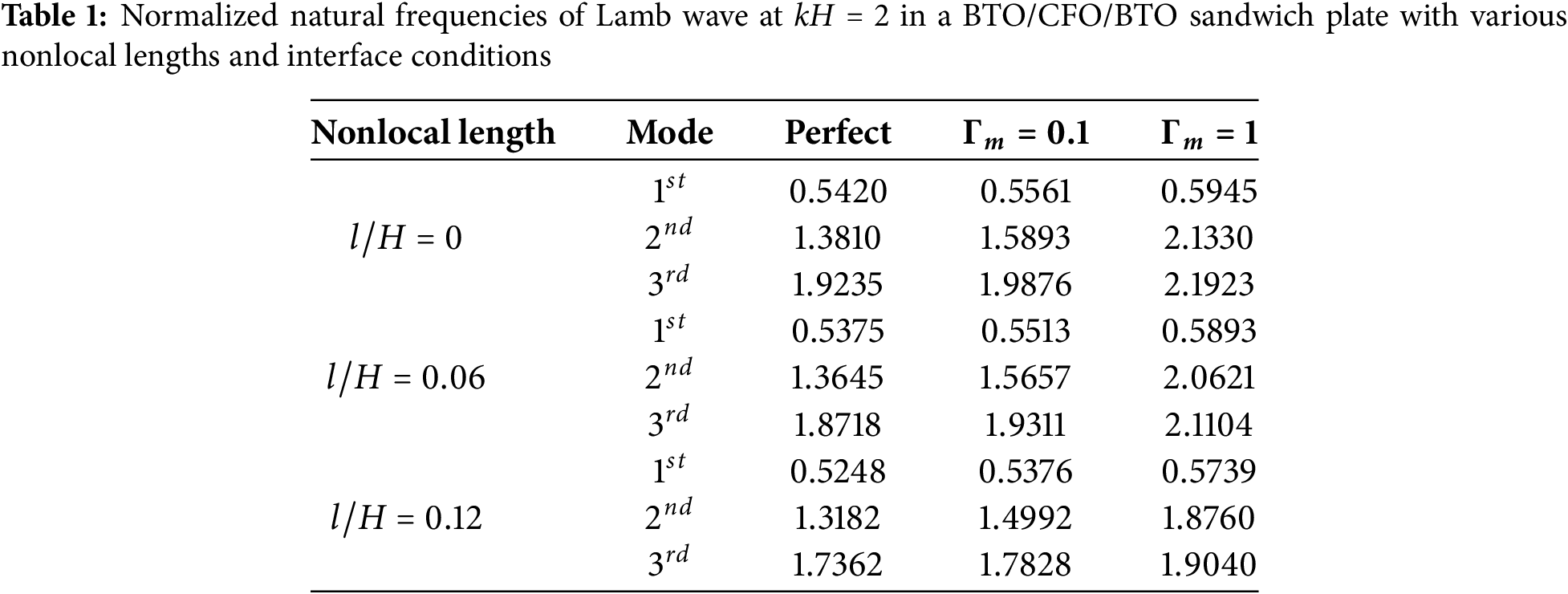
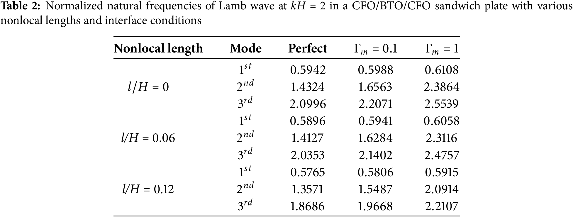
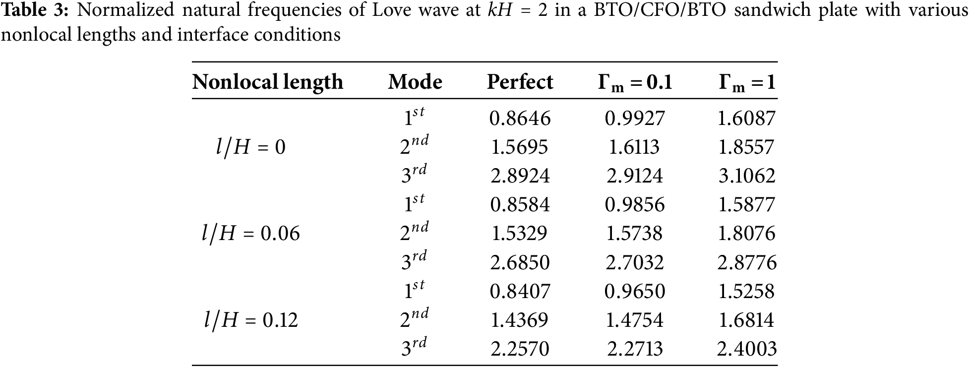
We further investigated the modal natural frequencies associated with different nonlocal lengths and interface imperfections at a given wavenumber. Tables 1 and 2 present the first three modal natural frequencies at wavenumber
Figs. 4 and 5 show the first-order (


Figure 4: Variations for the first-order mode shapes of the Lamb wave in a BTO/CFO/BTO plate along the thickness direction (dimensionless wavenumber kH = 2): (a, b) displacements

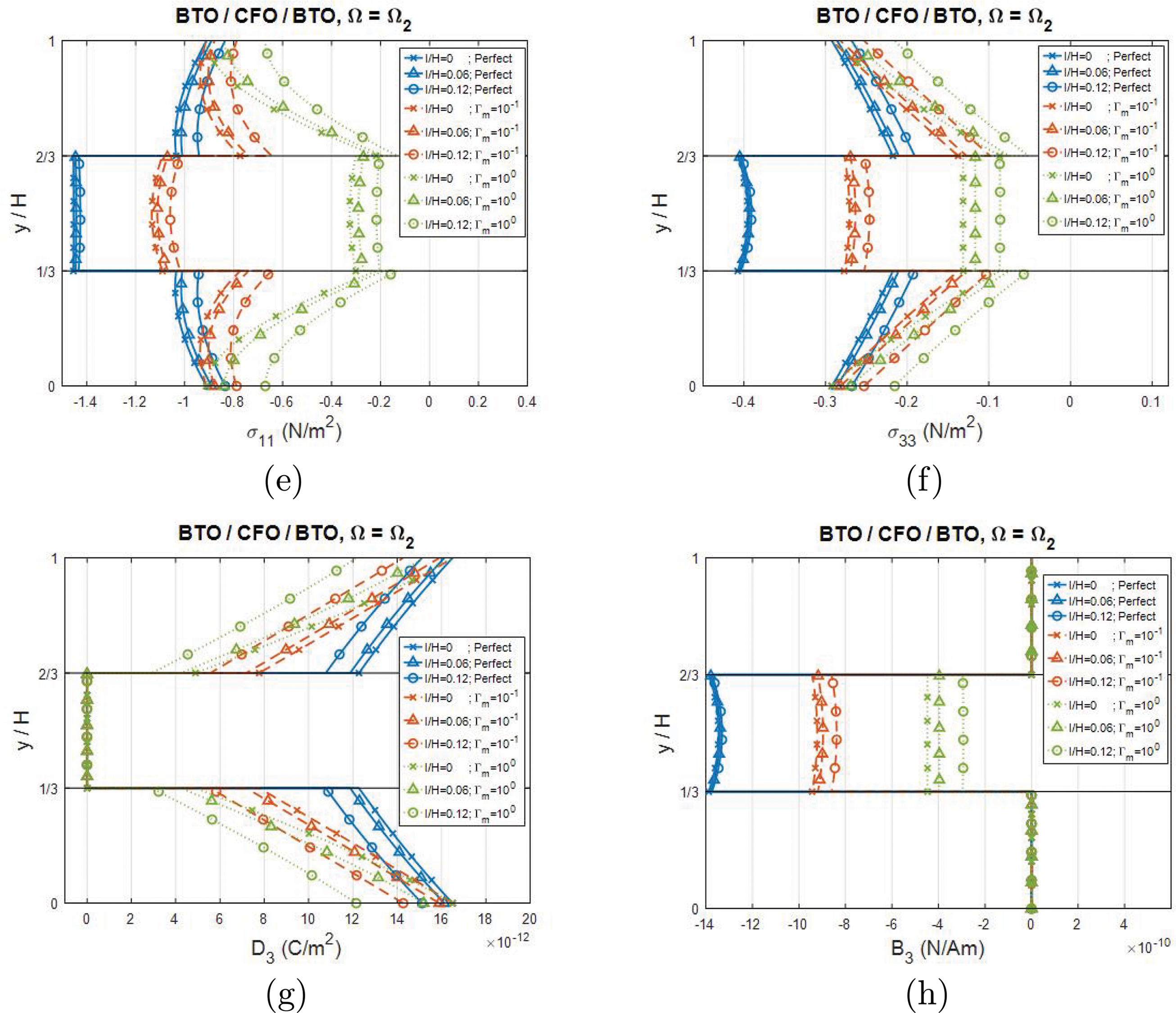
Figure 5: Variations for the second-order mode shapes of the Lamb wave in a BTO/CFO/BTO plate along the thickness direction (dimensionless wavenumber kH = 2): (a, b) displacements


Figure 6: Variations for the first-order mode shapes of the Lamb wave in a CFO/BTO/CFO plate along the thickness direction (dimensionless wavenumber kH = 2): (a, b) displacements


Figure 7: Variations for the second-order mode shapes of the Lamb wave in a CFO/BTO/CFO plate along the thickness direction (dimensionless wavenumber kH = 2): (a, b) displacements
Analysis of the corresponding second-order mode shapes (Figs. 5 and 7), revealed consistent pattern for both configurations: (1) The displacement
Figs. 8 and 9 show the variation of the first three dispersion curves for the Love wave in the BTO/CFO/BTO and CFO/BTO/CFO sandwich plate configurations under different nonlocal lengths and interfacial contact conditions. The analysis revealed that nonlocal effects significantly reduced dispersion values, particularly in high-frequency regimes (characterized by large wavenumbers and short wavelengths). Additionally, the nonlocal length modifications significantly altered the overall trend of the dispersion curves. The dispersion curves converged more rapidly as the nonlocal length increased. An increase in the nonlocal length resulted in a decrease in the slope of the curves. Furthermore, the effect of the interfacial imperfection was significant (Tables 3 and 4) for selected points at a wavenumber of
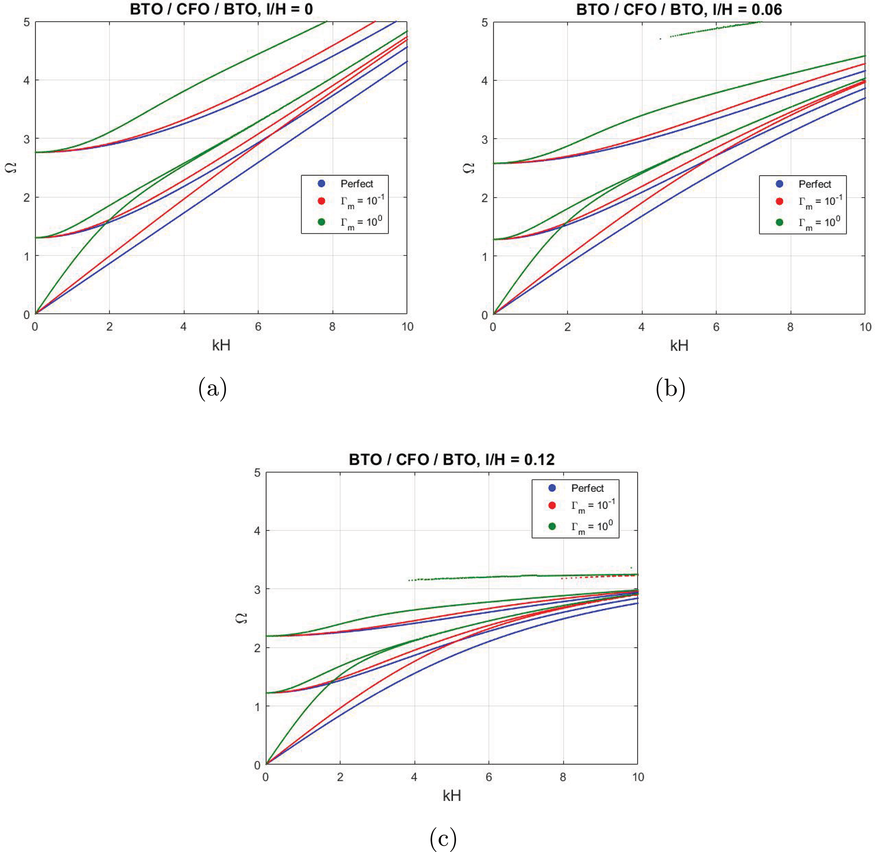
Figure 8: Dispersion curves for Love waves in a BTO/CFO/BTO sandwich plate with different interface contacts: perfect contact, imperfect contact with the relative scaling parameter
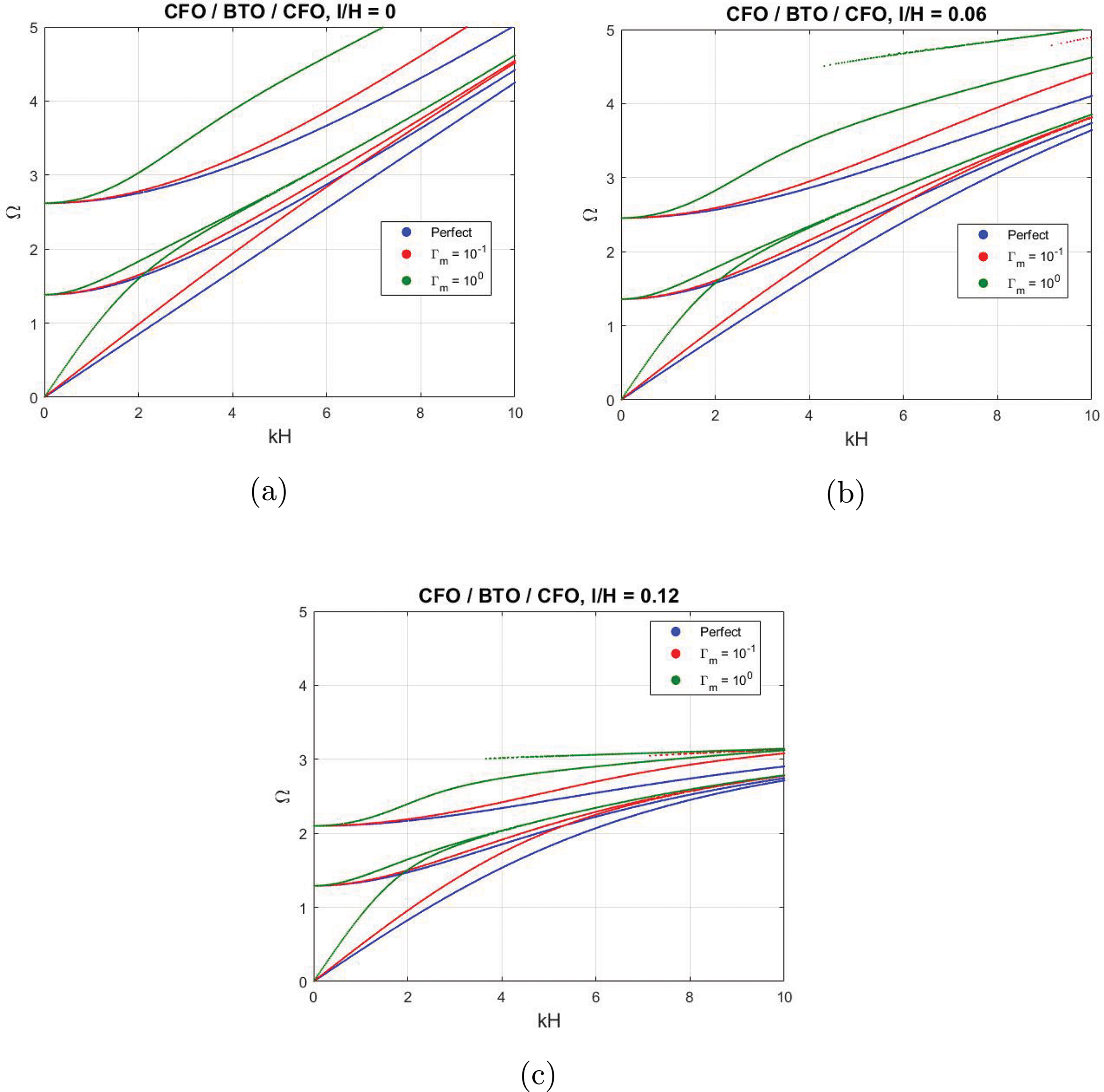
Figure 9: Dispersion curves for Love waves in a CFO/BTO/CFO sandwich plate with different interface contacts: perfect contact, imperfect contact with the relative scaling parameter

Figs. 10 and 11 illustrate thickness-wise distributions of the first-order and second-order mode shapes of the BTO/CFO/BTO plate at a wavenumber


Figure 10: Variations for the first-order mode shapes of the Love wave in a BTO/CFO/BTO plate along the thickness direction (dimensionless wavenumber kH = 2): (a–c) displacement


Figure 11: Variations for the second-order mode shapes of the Love wave in a BTO/CFO/BTO plate along the thickness direction (dimensionless wavenumber kH = 2): (a–c) displacement


Figure 12: Variations for the first-order mode shapes of the Love wave in a CFO/BTO/CFO plate along the thickness direction (dimensionless wavenumber kH = 2): (a–c) displacement


Figure 13: Variations for the second-order mode shapes of the Love wave in a CFO/BTO/CFO plate along the thickness direction (dimensionless wavenumber kH = 2): (a–c) displacement
For the second-order mode shapes (Figs. 11 and 13), the following features were observed for both plate configurations: (1) The distributions of
In this study, a comprehensive analytical framework was developed for predicting three-dimensional field distributions in nonlocal MEE laminates with interface stress imperfections. The methodology was used to generalize four key components: the pseudo-Stroh formulation, transfer matrix method, interface matrix method, and the nonlocal constitutive equation proposed by Eringen, which were collectively facilitate recursive field solutions. The key theoretical advancement involved the constructive relationship between the nonlocal and classical extended tractions fields. The analytical framework was illustrated through its application to BTO/CFO/BTO and CFO/BTO/CFO sandwich plates. The study revealed the following key findings: (1) both the nonlocal effect and interface stress-type imperfections significantly influenced the dispersion curves; (2) increasing the nonlocal length reduced the natural frequency, particularly in high-frequency regions; (3) increasing the severity of interface stress-type imperfections increases the natural frequency; (4) compared to the interface imperfections, the nonlocal effect has a less significant influence on the mode shapes of most field quantities; (5) the mode shapes of some field quantities exhibit similar behavior and appear insensitive to variations in the nonlocal length parameter; (6) interface stress-type imperfections reverses the direction and enhances the magnitude of the mode shapes, with the nonlocal effect further amplifying these changes.
While the current model effectively captures the local behavior of the investigated plate, its applicability to more complex laminated nanostructures may be limited. Specifically, the formulation may require an extension to address piezomagnetic facesheet configurations or a CNT composite layer with piezoelectric surface layers (common in energy harvesting applications). Future studies should focus on extending this framework to investigate these advanced MEE plate configurations, incorporate higher-fidelity plate theories (e.g., layer-wise or zigzag models), and improve local field distribution predictions in composite architecture [33].
Acknowledgement: The author is grateful to the editor and anonymous referees for their insightful comments and suggestions, which helped to improve the paper’s presentation.
Funding Statement: The study is supported by the Ministry of Science and Technology Taiwan under Grant No. MOST 109-2628-E-009-002-MY3.
Author Contributions: The authors confirm contribution to the paper as follows: study conception and design: Hsin-Yi Kuo; analysis and interpretation of results: Li-Huan Yang, Hsin-Yi Kuo; draft manuscript preparation: Li-Huan Yang, Hsin-Yi Kuo. All authors reviewed the results and approved the final version of the manuscript.
Availability of Data and Materials: All data that support the findings of this study are included within the article.
Ethics Approval: Not applicable.
Conflicts of Interest: The authors declare no conflicts of interest to report regarding the present study.
References
1. Eerenstein W, Mathur ND, Scott JF. Multiferroic and magnetoelectric materials. Nature. 2006;442(7104):759–65. doi:10.1038/nature05023. [Google Scholar] [PubMed] [CrossRef]
2. Vinyas M. Computational analysis of smart magneto-electro-elastic materials and structures: review and classification. Arch Comput Method Eng. 2021;28(3):1205–48. doi:10.1007/s11831-020-09406-4. [Google Scholar] [CrossRef]
3. Shetty S, Palkar VR, Pinto R. Size effect study in magnetoelectric BiFeO3 system. J Phys. 2002;58(5–6):1027–30. doi:10.1007/s12043-002-0211-4. [Google Scholar] [CrossRef]
4. Bühlmann S, Dwir B, Baborowski J, Muralt P. Size effect in mesoscopic epitaxial ferroelectric structures: increase of piezoelectric response with decreasing feature size. Appl Phys Lett. 2002;80(17):3195–7. doi:10.1063/1.1475369. [Google Scholar] [CrossRef]
5. Yoo K, Jeon BG, Chun SH, Patil DR, Lim YJ, Noh SH, et al. Quantitative measurements of size-dependent magnetoelectric coupling in Fe3O4 nanoparticles. Nano Lett. 2016;16(12):7408–13. doi:10.1021/acs.nanolett.6b02978. [Google Scholar] [PubMed] [CrossRef]
6. Eringen AC. On differential equations of nonlocal elasticity and solutions of screw dislocation and surface waves. J Appl Phys. 1983;54(9):4703–10. doi:10.1063/1.332803. [Google Scholar] [CrossRef]
7. Eringen AC. Nonlocal continuum field theories. New York, NY, USA: Springer; 2002. [Google Scholar]
8. Di Paola M, Failla G, Pirrotta A, Zingales M. The mechanically based non-local elasticity: an overview of main results and future challenges. Philos Trans A. 2013;371(1993):20120433. doi:10.1098/rsta.2012.0433. [Google Scholar] [PubMed] [CrossRef]
9. Wu C-P, Li W-C. Free vibration analysis of embedded single-layered nanoplates and graphene sheets by using the multiple time scale method. Computer Math Appl. 2017;73(5):838–54. doi:10.1016/j.camwa.2017.01.014. [Google Scholar] [CrossRef]
10. Wu C-P, Yu J-Y. A review of mechanical analyses of rectangular nanobeams and single-, double-, and multi-walled carbon nanotubes using Eringen’s nonlocal elasticity theory. Arch Appl Mech. 2019;89(9):1761–92. doi:10.1007/s00419-019-01542-z. [Google Scholar] [CrossRef]
11. Ke L-L, Wang Y-S, Yang J, Kitipornchai S. Free vibration of size-dependent magneto-electro-elastic nanoplates based on the nonlocal theory. Acta Mech Sinica. 2014;30(4):516–25. doi:10.1007/s10409-014-0072-3. [Google Scholar] [CrossRef]
12. Amiri A, Fakhari SM, Pournaki IJ, Rezazadeh G, Shabani R. Vibration analysis of circular magneto-electro-elastic nano-plates based on Eringen’s nonlocal theory. Int J Eng Trans. 2015;C 28:1808–17. [Google Scholar]
13. Pan E, Waksmanski N. Deformation of a layered magnetoelectroelastic simply-supported plate with nonlocal effect, an analytical three-dimensional solution. Smart Mater Struct. 2016;25(9):095013. doi:10.1088/0964-1726/25/9/095013. [Google Scholar] [CrossRef]
14. Waksmanski N, Pan E. An analytical three-dimensional solution for free vibration of a magneto-electro-elastic plate considering the nonlocal effect. J Intel Mater Syst Struct. 2017;28(11):1501–13. doi:10.1177/1045389x16672734. [Google Scholar] [CrossRef]
15. Ke L-L, Wang Y-S, Yang J, Kitipornchai S. The size-dependent vibration of embedded magneto-electro-elastic cylindrical nanoshells. Smart Mater Struct. 2014;23(12):125036. doi:10.1088/0964-1726/23/12/125036. [Google Scholar] [CrossRef]
16. Kuo H-Y. Effective moduli of multiferroic fibrous composites with strain gradient and electromagnetic field gradient effects. Int J Solids Struct. 2021;222–223:111007. doi:10.1016/j.ijsolstr.2021.02.018. [Google Scholar] [CrossRef]
17. Li G-E, Kuo H-Y. Effects of strain gradient and electromagnetic field gradient on potential and field distributions of multiferroic fibrous composites. Acta Mech. 2021;232(4):1353–78. doi:10.1007/s00707-020-02910-5. [Google Scholar] [CrossRef]
18. Liu C, Li. K, Min S, Chai Y. Dynamic analysis of the three-phase magneto-electro-elastic (MEE) structures with the overlapping triangular finite elements. Comput Math Appl. 2025;179:148–177.2. doi:10.1016/j.camwa.2024.11.025. [Google Scholar] [CrossRef]
19. Jiang Z, Gui Q, Li W, Chai Y. Assessment of the edge-based smoothed finite element method for dynamic analysis of the multi-phase magneto-electro-elastic structures. Eng Anal Bound Elem. 2024;163(3):94–107. doi:10.1016/j.enganabound.2024.02.021. [Google Scholar] [CrossRef]
20. Kuo H-Y, Yang L-H, Huang P-C, Pan E. Comparisons of wave characteristics in magneto-electro-elastic laminated composites with different layering directions. Acta Mech. 2023;234(9):4467–85. doi:10.1007/s00707-023-03611-5. [Google Scholar] [CrossRef]
21. Ly D-K, Vu H-N, Thongchom C, Nguyen-Thoi T. A multi-physical coupling isogeometric formulation for nonlinear analysis and smart control of laminated CNT-MEE plates. Eng Anal Bound Elem. 2024;159(13):36–57. doi:10.1016/j.enganabound.2023.11.023. [Google Scholar] [CrossRef]
22. Bichurin MI, Petrov VM, Srinivasan G. Theory of low-frequency magnetoelectric coupling in magnetostrictive-piezoelectric bilayers. Phys Rev B. 2003;68(5):054402. doi:10.1103/physrevb.68.054402. [Google Scholar] [CrossRef]
23. Wang Y, Su Y, Li J, Weng GJ. A theory of magnetoelectric coupling with interface effects and aspect-ratio dependence in piezoelectric-piezomagnetic composites. J Appl Phys. 2015;117(16):164106. doi:10.1063/1.4919016. [Google Scholar] [CrossRef]
24. Kuo H-Y, Chung C-Y. Multiferroic laminated composites with interfacial imperfections and the nonlocal effect. Compos Struct. 2022;287:115235. doi:10.1016/j.compstruct.2022.115235. [Google Scholar] [CrossRef]
25. Kuo H-Y, Wang Y-H. Wave motion of magneto-electro-elastic laminated plates with membrane-type interfacial imperfections. Compos Struct. 2022;293:115661. doi:10.1016/j.compstruct.2022.115661. [Google Scholar] [CrossRef]
26. Kuo H-Y, Huang P-C. Nonlocal free vibration of magneto-electro-elastic nanoplates with imperfect contacts. Mech Adv Mater Struct. 2024;31(30):12759–73. doi:10.1080/15376494.2024.2328753. [Google Scholar] [CrossRef]
27. Dong S, Li J-F, Viehland D. Longitudinal and transverse magnetoelectric voltage coefficients of magnetostrictive/piezoelectric laminate composite: experiments. IEEE Trans Ultras, Ferroelectr Frequ Control. 2004;51(7):794–9. doi:10.1109/tuffc.2004.1320738. [Google Scholar] [PubMed] [CrossRef]
28. Wang Y, Or SW, Chan HLW, Zhao Z, Luo H. Enhanced magnetoelectric effect in longitudinal-transverse mode Terfenol-D/Pb(Mg1/3Nb2/3)O3-PbTiO3 laminate composites with optimal crystal cut. J Appl Phys. 2008;103(12):124511. doi:10.1063/1.2943267. [Google Scholar] [CrossRef]
29. Zhai J, Xing Z, Dong S, Li J, Viehland D. Magnetoelectric laminate composites: an overview. J Am Ceram Soc. 2008;91(2):351–8. doi:10.1111/j.1551-2916.2008.02259.x. [Google Scholar] [CrossRef]
30. Benveniste Y, Miloh T. Imperfect soft and stiff interfaces in two dimensional elasticity. Mech Mater. 2001;33(6):309–23. doi:10.1016/s0167-6636(01)00055-2. [Google Scholar] [CrossRef]
31. Chen J, Guo J, Pan E. Wave propagation in magneto-electro-elastic multilayered plates with nonlocal effect. J Sound Vibrat. 2017;440:550–63. doi:10.1016/j.jsv.2017.04.001. [Google Scholar] [CrossRef]
32. Zhu F, Wang B, Qian ZH. A numerical algorithm to solve multivariate transcendental equation sets in complex domain and its application in wave dispersion curve characterization. Acta Mech. 2019;230(4):1303–21. doi:10.1007/s00707-017-2025-y. [Google Scholar] [CrossRef]
33. Ly D-K, Vu-Do H-C, Thongchom C, Nguyen-Thoi T. A multiscale and multiphysical numerical approach for sandwich multiphasehybrid fiber plates with smart composite facesheets. Eng Anal Bound Elem. 2025;173(03):106134. doi:10.1016/j.enganabound.2025.106134. [Google Scholar] [CrossRef]
Cite This Article
 Copyright © 2025 The Author(s). Published by Tech Science Press.
This work is licensed under a Creative Commons Attribution 4.0 International License , which permits unrestricted use, distribution, and reproduction in any medium, provided the original work is properly cited.
 Downloads
 Citation Tools