
 Submit a Paper
 Propose a Special lssue
 Open Access
ARTICLE

Analytical and Numerical Study of the Buckling of Steel Cylindrical Shells Reinforced with Internal and External FRP Layers under Axial Compression
1 Mechanical Engineering Department, Petroleum-Gas University of Ploiesti, Ploiesti, 100680, Romania
2 Department of Mathematical Modeling and Intelligent Computing in Engineering, National Technical University-Kharkov Polytechnic Institute, Kharkov, 61002, Ukraine
* Corresponding Author: Maria Tănase. Email:
(This article belongs to the Special Issue: Advances in Numerical Modeling of Composite Structures and Repairs)
Computer Modeling in Engineering & Sciences 2025, 144(1), 717-737. https://doi.org/10.32604/cmes.2025.067891
Received 15 May 2025; Accepted 10 July 2025; Issue published 31 July 2025
 View Full Text
 Download PDF
Abstract
Steel cylindrical shells are widely used in engineering structures due to their high strength-to-weight ratio, but they are vulnerable to buckling under axial loads. To address this limitation, fiber-reinforced polymer (FRP) composites have emerged as promising materials for structural reinforcement. This study investigates the buckling behavior of steel cylindrical shells reinforced with inner and outer layers of polymer composite materials under axial compression. Using analytical and numerical modeling methods, the critical buckling loads for different reinforcement options were evaluated. Two-sided glass fiber reinforced plastic (GFRP) or carbon fiber reinforced plastic (CFRP) coatings, as well as combined GFRP+CFRP coatings with layers of different composites, were considered. In the calculations, the coatings were treated as homogeneous orthotropic materials with equivalent averaged elastic characteristics. The numerical analysis revealed that CFRP reinforcement achieved the highest increase in buckling load, with improvements ranging from 9.84% to 47.29%, depending on the composite thickness and steel shell thickness. GFRP reinforcement, while beneficial, demonstrated a lower effectiveness, with buckling load increases between 5.89% and 19.30%. The hybrid GFRP+CFRP reinforcement provided an optimal balance, improving buckling resistance by 6.94% to 43.95%. Statistical analysis further identified composite type and thickness as the most significant factors affecting buckling performance. The findings suggest that CFRP is the preferred reinforcement material, especially when applied to thin-walled cylindrical shells, while hybrid reinforcements can be effectively utilized for structures requiring a balance between stiffness and ductility. These insights provide a foundation for optimizing FRP reinforcement strategies to enhance the structural integrity of steel shells in engineering applications.Keywords
Cylindrical steel shells are widely used in various engineering applications, including storage tanks, pipelines, and pressure vessels. However, these structures are susceptible to buckling failure under axial compression, which can compromise their structural integrity [1–5].
Several researchers have focused on enhancing the load-bearing capacity of steel cylindrical shells, often by incorporating ring stiffeners or stringers on the surface [6–10]. Tanase et al. [11] provide a technical-economic optimization framework for structural components, showing how cost-effective design can improve buckling resistance. This concept of optimization is also explored by Al-Kalali [6], who investigates the optimal design of cylindrical stiffener shells under hydrostatic pressure, emphasizing the need for both structural integrity and material efficiency.
Shiomitsu and Yanagihara [7] delve into the ultimate strength of ring-stiffened shells, considering local and torsional buckling, further expanding the understanding of how stiffeners impact shell stability.
In a similar investigation, Zhang et al. [8] highlight the significant role of rings in enhancing the buckling strength of cylindrical shells, while Andrianov et al. [12] provide a detailed analysis of discretely stringer-stiffened shells, showing how different reinforcement patterns affect buckling behavior. These studies are complemented by Spagnoli and Chryssanthopoulos [13], whose research on stringer-stiffened conical shells offers insights into similar cylindrical structures, illustrating the broader applicability of stiffening techniques.
Further investigations into failure modes and damage tolerance are presented by Cho et al. [10], who examine ring-stiffened cylinders under external pressure, and Cho et al. [9], who assess the residual strength of damaged cylinders.
Finally, Li et al. [14] confirm the effectiveness of ring stiffeners in enhancing axial compression resistance, providing experimental and numerical validation for the role of stiffeners in improving the load-bearing capacity of cylindrical shells.
On the other hand, to enhance the buckling resistance of thin-walled cylindrical shells, Fiber Reinforced Polymer (FRP) composites have emerged as a promising strengthening solution [15–19]. Several studies have explored different FRP reinforcement strategies to mitigate buckling effects and improve the load-carrying capacity of metallic cylindrical shells.
Study [20] numerically investigates the buckling behavior of thin metallic cylindrical shells wrapped with FRP composites, emphasizing how buckling characteristics influence strengthening effectiveness. Results show that elastic buckling shells benefit from increased FRP hoop modulus, while plastic buckling shells with asymmetric failure modes achieve optimal performance with minimal longitudinal FRP stiffening.
Another study [21] evaluates the impact of a CFRP composite layer on the buckling behavior of metallic cylindrical shells, as an alternative to traditional metallic stiffeners. Experimental tests show significant improvements in bearing capacity, and the results align well with a developed numerical model.
Another work [17] presents a numerical study on the buckling pressure. Using nonlinear stability analysis in ABAQUS, it evaluates different reinforcement layouts across various slenderness ratios, showing that all reinforcement configurations enhance buckling stability, with circumferential CFRP strips at the midsection ([0°] fiber angle) proving most effective.
Krishna et al. [22] examine the buckling behavior of FRP-strengthened aluminum cylindrical shells with geometric imperfections and cut-outs and find that FRP strengthening is more effective for shells with cut-outs, improves buckling resistance, and is particularly beneficial for shells with small imperfections. The study also reveals that elliptical cut-outs offer better resistance than rectangular ones, and FRP strengthening enhances performance, especially for shells with smaller initial imperfections.
Wang et al. [15] investigate the buckling behavior of steel-composite cylindrical shells under axial compression, deriving a theoretical formula for the linear elastic buckling of steel-composite cylindrical shells, and conducting numerical analyses to verify the solution. Results show that the theoretical and numerical values agreed well, with deviations under 20%, while the steel-composite shells demonstrated lower imperfection sensitivity and higher load capacity than regular steel shells, offering valuable insights for their design and evaluation.
Also, the effects of carbon fiber orientations on strengthening small-scale thin-walled steel cylinders (TSCs) under axial compression were investigated both experimentally and numerically by Nhut et al. [23]. Additionally, the impact of various types of carbon fiber reinforced polymers (CFRPs) on the load-carrying capacity of full-scale TSCs was numerically explored and the results showed that circumferential CFRP layers (0°) significantly improved the load-carrying capacity, while 90° CFRP layers had minimal strengthening effects. For TSCs subjected to bending shear loads with high internal pressures, circumferential fibers provided better strengthening than angled fibers.
The paper [19] explores the inelastic buckling of steel tubes strengthened with glass fiber-reinforced polymer (GFRP) composites, taking into account different factors such as boundary conditions, geometric imperfections, transverse moduli of GFRP, interfacial bonding between metal and FRP, and FRP damage.
Batikha et al. [24,25] investigated the phenomenon of elephant’s foot buckling, a type of elastic-plastic instability failure that occurs near the base of cylindrical shells. Their innovative approach involved using FRP composites in carefully selected areas to enhance resistance to this failure mode. In their first study [24], they utilized linear elastic bending theory to show that the effectiveness of FRP strengthening depends significantly on factors such as the thickness, height, and placement of the FRP sheets. In a subsequent study [25], they expanded their analysis to consider additional factors like shell height, and thickness ratios, optimizing the size and placement of FRP bands. Their results revealed that even small changes in the FRP parameters had a major impact on the shell’s performance, highlighting the critical importance of precise design and placement for effective reinforcement.
Features of the stability loss of layered hollow shells with porous materials are considered in articles [26,27], taking into account the non-uniform distribution of compressive forces at the shell boundaries. The originality of these studies lies in taking into account different porosity distribution patterns. Porous material properties are modeled along the thickness using trigonometric functions. The governing equations for the buckling problem are solved via Galerkin’s method. Based on parametric analysis, the influence of the degree of porosity, orthotropy of components, directions of fiber reinforcement, etc., on the critical forces was established.
While previous research has focused on either CFRP or GFRP reinforcement independently, this study uniquely evaluates their combined effect, demonstrating that hybrid CFRP+GFRP reinforcement provides a well-balanced solution for applications requiring both strength and flexibility.
The increasing use of shells in various branches of the chemical and aerospace industries leads to different requirements for internal and external coatings. This determines the relevance of research on the stability of cylindrical shells with various two-sided coatings. The purpose of this study is to develop a methodology for determining critical loads in cylindrical shells with two-sided composite coverings. Extensive results of numerical calculations are used to statistically analyse the influence of design parameters and material properties on the loss of stability of three-layer shells.
The mathematical model is based on the linear theory of cylindrical shells. The peculiarities of shells with two-sided covers are reflected by the introduction of integral forces and moments. The proposed relations allow taking into account the differences in the elastic properties of the layers and their anisotropy. Governing relationships are obtained under the assumption of perfect contact between the coatings and the base metal and without taking into account possible delaminations and failure in composite coatings. Unlike conventional studies that assess reinforcement without considering the interplay between structural parameters, this research reveals how steel shell thickness, composite thickness, and reinforcement type interact, allowing for a more refined and application-specific optimization. Such optimization is important from an economic point of view in large shell elements of chemical engineering structures and cylindrical columns of ocean platforms and wind turbines. Weight optimization is critical for the aerospace industry.
2 Theoretical Foundations of the Formulation of the Stability Problem
When constructing constitutive relations, the linear Donnell shell theory is used. Donnell shell theory uses a simplified set of equations to analyze the behavior of thin shells, in particular shells of zero Gaussian curvature. In the geometrical relations for curvature changes, the contribution of displacements u and v is not taken into account because of their small ratios to the radii of the principal curvatures. In addition, the first quadratic form of the cylindrical surface corresponds to the Euclid’s metric of the plane. This leads to a wide application of Donnell’s theory to analyze the stability of cylindrical shells under axial compression.
The middle surface of the shell is referred to the cylindrical coordinate system r,
where u, v, w—are the displacements in the axial, circumferential and normal directions, respectively, R—is the radius of the middle surface of the shell.
The parameters for changing the curvature and torsion of the middle surface have the form:
When considering the geometric relationships of a multilayer cylindrical shell, the direct normal hypothesis is used for the entire package of layers. The components of the deformation tensor of points lying at a distance z from the middle surface are expressed in terms of the deformation parameters of the middle surface:
The geometrical relations (3) are based on the hypothesis of straight normal for the whole package of layers and perfect contact between the layers. In cases of technological defects, delamination may occur, which lead to a decrease in critical loads. However, theoretical analysis of the stability of shells with delamination requires consideration of the contact interaction in the defect zone, which requires a nonlinear formulation of the problem.
Physical relations for all layers are written taking into account the static hypotheses of shell theory
Elastic moduli, shear moduli and Poisson’s ratios can have different values for each of the three layers. The linear forces per unit length of the line of the middle surface are introduced taking into account the difference in the elastic characteristics of the layers.
here h1, h3 are the thicknesses of the composite coatings, h2 is the thickness of the steel shell (Fig. 1). The superscript in brackets means that the stresses are calculated using formulas in (4) with the elasticity characteristics of the corresponding layer. Linear bending and torque moments are introduced in a similar way.

Figure 1: Cross-section of the wall of a cylindrical shell
To study the stability of three-layer orthotropic shells using the energy method, it is necessary to obtain expressions for the total potential energy of the shell—external load system. The energy of elastic deformation of the shell for small deviations from the ideal initial shape can be written in the form of a functional defined on the possible displacements of points on the middle surface:
where L—is the length of the cylindrical shell.
The work of external forces depends on the type of applied loads. The most common cases of buckling are related to axial compressive force and external pressure. If the shell is loaded at the ends with axial uniform compressive forces so that the subcritical stress state is membrane
Based on Lagrange’s variation principle, the actual displacements during loss of stability deliver a minimum to the functional
To find the displacements that deliver the minimum functional of the total energy, the finite element method is used.
3 Application of the Finite Element Method
3.1 Finite Element Formulation of the Multilayer Shell Stability Problem
The energy of elastic deformation of the shell (7) is written in the form of a quadratic form of nodal displacements:
where {u} is the vector of displacement values at the nodes of the finite element mesh, [K]—is the global stiffness matrix of the finite element model. Due to the linear dependence of the work of external forces on the compressive force, we write this work accurate to scalar factor λ:
where [D] is the global differential matrix for a unit value of the compressive force. The discrete form of the total energy of the system takes the form of a function depending on the nodal displacements and the parameter λ:
The equilibrium conditions for the perturbed state correspond to the minimum total energy:
This leads to the problem of finding nontrivial values of a linear homogeneous system of algebraic equations with respect to nodal displacements. Each root of the equation:
corresponds to its eigen form of buckling of the shell and the corresponding critical force. The number of roots of Eq. (14) is equal to the number of degrees of freedom of the finite element model. Several smallest values of the critical load are of greatest practical interest.
The ANSYS software package was used to perform numerical studies on the stability of cylindrical shells with two-sided composite covers (Fig. 1).
The ANSYS software package uses shell elements for structural and stability analysis of shells. They allow analyzing multilayer elements as well. In cases of layers asymmetric with respect to the median surface, it is possible to introduce a reference surface that does not coincide with the median surface. When analyzing the stability of cylindrical shells compressed along the shells by Nx force, it is assumed that the unperturbed state is momentless. This condition will be fulfilled for asymmetric layers if the bending moment with respect to the reference surface is zero when the deformation
here z∗ is the distance of the reference surface from the median surface, and the stresses are constant within each layer and are determined by its elastic properties.
here the superscript (k) specifies the layer number. Eq. (15) defines the distance of the reference surface from the mid-surface of the middle layer.
For specific values of layer thicknesses and their elastic characteristics, the the distance z* is set in the “Section” settings as “Section Offset” by choosing “User-Input-Location” in preprocessor ANSYS software package.
3.2 Creating Geometric Models and Performing Numerical Analysis
The finite element (FE) method was chosen to validate the corresponding theoretical solutions, and linear eigenvalue analyses were conducted using the commercial software ANSYS 2021 R1. The influence of structural parameters on the buckling response was systematically examined.
The cylindrical shell was considered to have the height L = 5000 mm and radius R = 5000 mm. To perform a parametric study, the steel layer thickness h2 was considered as 8, 10 and 12 mm, while the thickness of composite layers h1 = h3 was 1, 2 and 3 mm.
A second-order finite element SHELL281 was used to create discrete models. This element has eight nodes with six degrees of freedom at each node: translations in the x, y, and z axes, and rotations about the x, y, and z-axes. Element SHELL281 makes it possible to simulate layered structures with anisotropic materials. Special settings of the SHELL 281 element allow to take into account different orientation of the main directions of orthotropy of elastic properties of composite layers with respect to the global coordinate system. Perfect bonding interface between the steel and composite layers was assumed. The accuracy in modeling composite shells is governed by the first-order shear-deformation theory. The finite element model of the shell consisted of 53,136 nodes and 17,496 elements. The criterion for sufficient accuracy in technical calculations is the coincidence of nodal and element stress values to within one per cent. On the mesh used these values for equivalent stresses coincided to within three significant digits.
The model of shell contained three layers, as seen in Fig. 2. The first and the third layers represent the composite material, while the middle layer is represented by steel shell. The properties of composite layers are presented in Table 1.
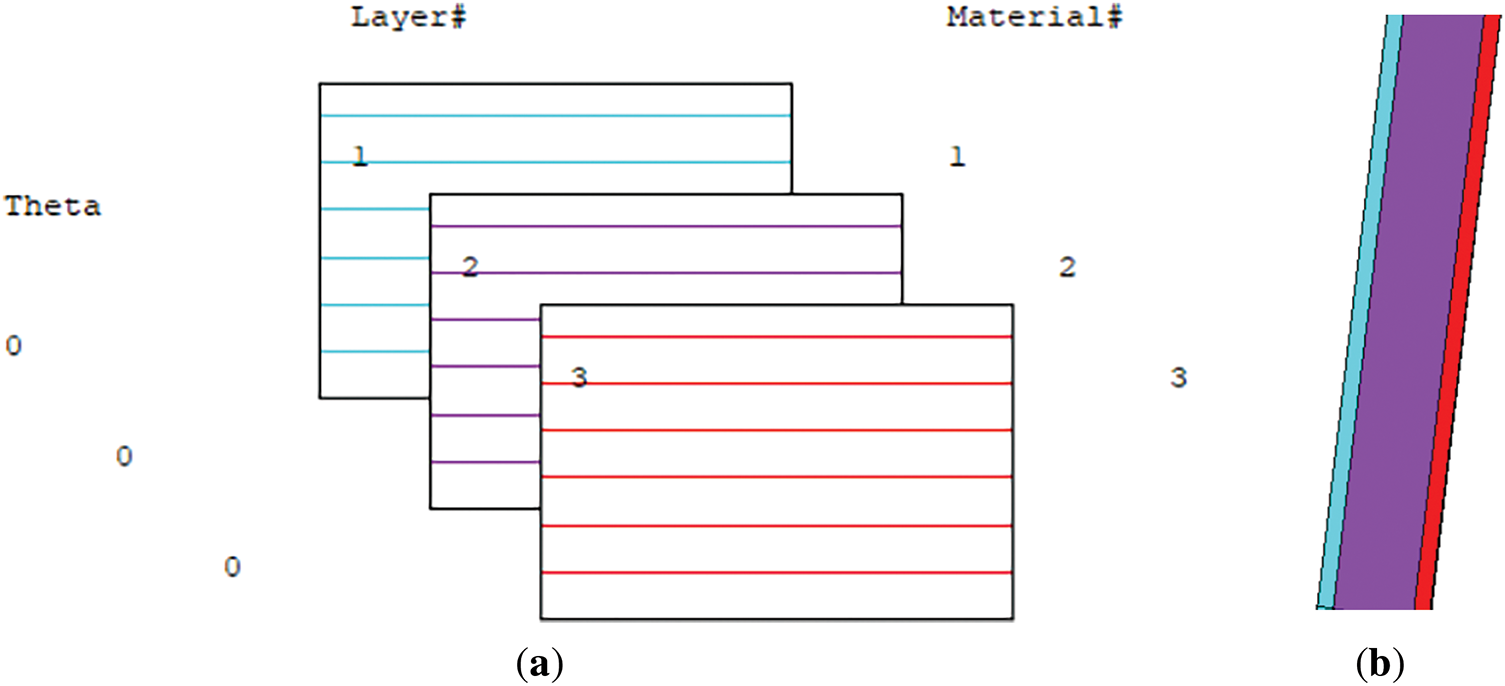
Figure 2: FE model of the steel shell reinforced with two composite layers: (a) defining the layers properties; (b) detailed view on shell thickness

Before performing the investigation, a mesh convergence analysis was made in order to validate the results of numerical analysis. Firstly, it was calculated the critical buckling load for a steel cylindrical shell under axial compression with the formula of Timoshenko [28,29]:
where E is Young’s modulus, MPa, t is the shell wall thickness, mm, and R is the mean radius of cylinder, mm.
In case of analyzed shell with L = 5000 mm, R = 5000 mm and thickness t = h2 = 10 mm, it results Pcr = 2541 N/mm.
The boundary conditions were set as: at the cylinder base UX = UY = UZ = 0, while at the other part of cylinder where the unit load of 1 N/mm was applied (on OY direction) it was considered UX = UZ = 0 (see Fig. 3a).

Figure 3: Numerical modeling: (a) loads and boundary conditions; (b) buckling mode shape for isotropic shell
After mesh convergence analysis (Fig. 4), it was adopted a 200 mm mesh size to ensure computational efficiency, since the critical buckling load was obtained in this case 2540.61 N/mm, very close to the analytical value, as observed in Fig. 3b.

Figure 4: Mesh sensitivity analysis for critical buckling load
4 Theoretical Stability Analysis of Thin Orthotropic Shells
The analytical proposed method is based on the use of stability equation for an orthotropic shell under axial compression [30,31]:
To determine the buckling load from Eq. (19), it is necessary to minimize the expression of load for discrete integer values of m (the number of axial half-waves) and n (the number of circumferential full waves).
Eq. (19) utilizes the following notations: L represents the cylinder length, while R denotes its mean radius. The wall thickness is given by t. The Poisson’s ratios in the longitudinal and circumferential directions are µx and µy, respectively. The extensional stiffnesses in these directions, Ex, Ey, are specified by Eqs. (20) and (21). Similarly, the bending stiffnesses, Dx, Dy follow from Eqs. (22) and (23). The in-plane shear stiffness, Gx, is defined in Eq. (24), while the twisting stiffness, Dxy is given in Eq. (25).
For a metallic shell reinforced with on both internal and external surface with layers of composite material, the parameters from Eqs. (20), (21) and (24) were recalculated for a three-layers shell. The approximations made include:
Theoretical stability analysis of thin orthotropic shells uses cylindrical stiffness parameters. For three-layer shells with asymmetric arrangement of layers, these parameters are determined relative to the reference surface from Fig. 1, as:
This study employs an advanced statistical prediction model to systematically analyze the obtained data, aiming to identify the optimal configuration and assess the influence of various factors—such as, metallic shell thickness, composite thickness, and composite material type—on the buckling behavior of FRP-strengthened metallic cylindrical shells. A full factorial design of experiments (DOE) approach is utilized, implemented using the statistical software Minitab 19. The investigated parameters and their corresponding three-level variations are detailed in Table 2.

Therefore, it resulted a number of 27 tests, as presented in Table 3. The following designations are adopted here for the various combinations of coatings.

GFRP/GFRP—double-sided glass fiber reinforced polymer composites coatings.
CFRP/CFRP—double-sided carbon fiber reinforced polymer composites coatings.
GFRP/CFRP—inner coating with carbon fiber reinforced polymer composite and outer coating with glass fiber reinforced polymer composite.
6.1 Analytical and Numerical Results
The analytical and numerical results regarding axial critical buckling load are shown in Table 4. The column titled “Increase in buckling load (%)” in Table 4 quantifies the relative enhancement in the critical buckling load achieved through FRP reinforcement, compared to the baseline performance of an unreinforced steel cylindrical shell (calculated with Formula (18)).

It can be observed that the analytical and numerical results are very close, the maximum difference between the analytical and numerical results, 6.21%, occurred in Test 27, which involved the thickest hybrid composite configuration (GFRP/CFRP with 3 mm thickness each). This discrepancy arises due to the simplifying assumptions in the analytical model—such as perfect geometry, linear elasticity, and averaged material properties—which do not fully account for the complex interfacial effects, stiffness gradients, and boundary layer behavior captured in the finite element simulations. Nonetheless, a deviation of 6.21% is within the range of acceptable accuracy for engineering design. It confirms that the analytical model provides reliable estimations and validates the general trend observed in the numerical simulations, especially for use in parametric and optimization studies where exact matching is less critical than capturing the behavior trends.
As shown in Table 4, increasing the composite thickness from 1 mm to 3 mm resulted in up to a 47.29% increase in buckling resistance, indicating a strong dependence on the reinforcement ratio. Additionally, thinner steel shells, (h2 = 8 mm) benefited more from FRP strengthening due to their higher susceptibility to local buckling, which the composite layers effectively constrained.
As shown in Fig. 5, the FRP-reinforced cylindrical steel shell exhibits a more uniform deformation pattern and higher overall stiffness compared to the unstiffened shell depicted in Fig. 3b. The reinforced shell demonstrates delayed buckling and localized displacement, whereas the unstiffened configuration (Fig. 3b) shows pronounced global instability with higher deformation amplitudes concentrated along the vertical axis, indicating a lower load-carrying capacity.

Figure 5: Example of failure mode of steel cylindrical shell reinforced with FRP
Fig. 6 presents the axial critical buckling load variations for different reinforcement types: GFRP, CFRP, and the hybrid combination of GFRP+CFRP. It is evident that CFRP reinforcement yields the highest buckling resistance due to its superior stiffness and strength compared to GFRP. This can be attributed to the higher elastic modulus of CFRP, which allows the reinforced shell to resist axial compression more effectively. The hybrid reinforcement (GFRP+CFRP) further enhances buckling resistance, benefiting from the combination of CFRP’s high stiffness and GFRP’s flexibility, which overall structural performance.

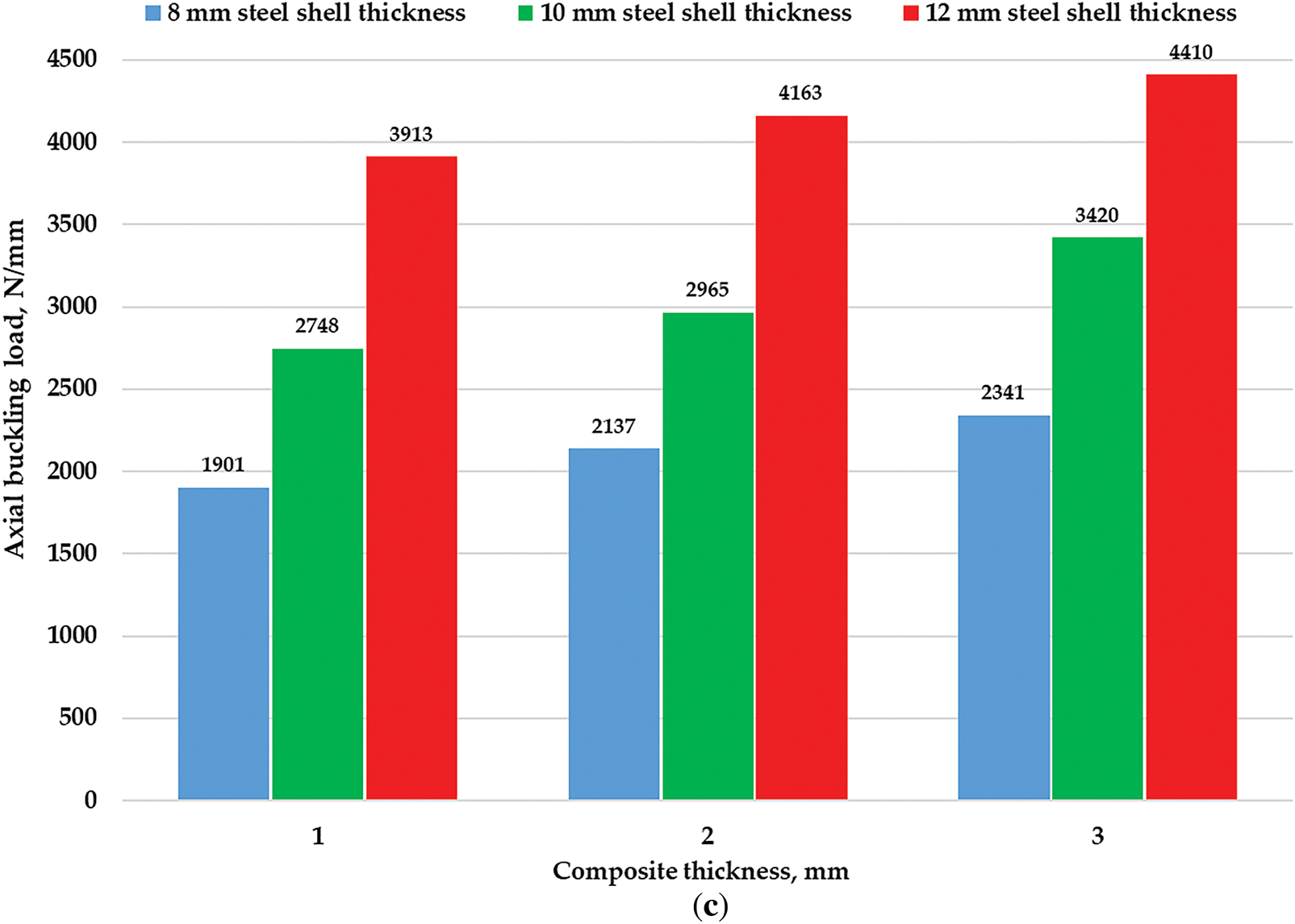
Figure 6: The values of axial critical buckling load for different types of composite reinforcement: (a) GFRP reinforcement; (b) CFRP reinforcement; (c) GFRP+CFRP reinforcement
Similarly, Ref. [16] have demonstrated that increasing the thickness of CFRP or GFRP layers leads to a significant enhancement in buckling resistance, consistent with our findings. Also, the results from Ref. [15] showed that compared to the normal steel cylindrical shell, the steel–composite cylindrical shell possessed lower imperfection sensitivity and higher load-carrying capacity.
The presented results are further supported by findings in the Ref. [20] which emphasize the role of FRP stiffness in buckling performance. It has been shown that the elastic modulus of the FRP wrap influences the effective stiffness of the strengthened shell only when it exceeds that of the metallic substrate. For elastically buckling shells with wall thickness much greater than the FRP layer, only the hoop modulus of the FRP (i.e., the modulus in the circumferential direction) significantly affects the buckling load, while increases in axial modulus have little to no effect. This is because buckling in cylindrical shells under axial compression is often triggered by circumferential deformation patterns, and increasing the hoop stiffness resists these out-of-plane deformations more effectively, thereby delaying instability. In contrast, the axial modulus does not directly resist the lateral deformation modes that drive buckling. However, for thinner shells, where the overall shell is more flexible and the FRP layer contributes a higher proportion of the composite stiffness, increasing the axial modulus of the FRP wrap can significantly enhance the ultimate buckling load. In such cases, both axial and hoop stiffness become important. These observations confirm and explain our findings that both composite type (i.e., material modulus) and layer thickness play critical roles in influencing the buckling resistance, particularly in shells with smaller steel wall thicknesses.
In Fig. 7, the increase in the critical buckling load is shown as a function of reinforcement type and thickness.

Figure 7: Increase of critical buckling load
The results indicate that, for all reinforcement types, increasing the composite thickness leads to an enhancement in buckling resistance. This suggests that while adding more composite layers strengthens the shell, there exists a point where additional thickness provides diminishing returns due to local instability effects. Moreover, the rate of improvement is more pronounced in CFRP-reinforced shells, which demonstrates that the material’s superior mechanical properties make it more effective in carrying axial loads. The hybrid reinforcement also exhibits a notable increase in buckling resistance, indicating that the combination of CFRP and GFRP creates a synergistic effect where stiffness and ductility are balanced. The steel shell thickness also plays a role, with thinner shells benefiting more from composite reinforcement.
To gain deeper insight into the factors affecting the buckling behavior of steel cylindrical shells reinforced with FRP, a statistical analysis was conducted. This included determining the main effects plots for the critical buckling load increase (Fig. 8), interaction plots (Fig. 9), as well as the Pareto chart (Fig. 10).

Figure 8: Main effects plot for buckling load increase

Figure 9: Interaction plots for buckling load increase

Figure 10: Pareto charts for buckling load increase
The plot reveals that composite thickness has the most substantial impact, confirming that as additional layers are applied, the shell gains stability against axial compression. The second most influential factor is composite type, reinforcing the idea that CFRP outperforms GFRP not only due to its higher elastic modulus, but also because the increased stiffness provided by CFRP enhances the overall axial rigidity of the shell, effectively delaying the onset of buckling. This improved confinement of radial and circumferential deformations contributes to a greater increase in critical buckling load. However, the effectiveness of increasing composite thickness is more pronounced in thinner steel shells, as the additional reinforcement compensates for their lower intrinsic stiffness. On the other hand, the influence of steel shell thickness follows a less steep trend, suggesting that although thicker steel layers improve buckling resistance, the benefits are moderate compared to composite reinforcement. This aligns with the fact that steel itself already provides significant structural integrity, making the additional reinforcement less critical for thicker shells.
Expanding on this, Fig. 9 presents interaction plots, which reveal how different factors work together to influence buckling resistance. The interaction between steel thickness and composite thickness is particularly interesting, as it shows that the benefits of composite reinforcement are more significant for thinner steel shells. This suggests that reinforcement is most effective when applied to structures that are inherently more susceptible to buckling, making it a valuable technique for lightweight engineering applications. Another key interaction is between composite type and thickness—while increasing CFRP thickness results in a substantial improvement in buckling load, GFRP reinforcement exhibits a more gradual increase. This indicates that CFRP reinforcement is more effective in thinner layers because its higher stiffness-to-thickness ratio provides significant buckling resistance without the need for substantial thickness increase. In contrast, GFRP requires a thicker application to offer a comparable stabilizing effect due to its lower modulus, which makes it less efficient in thin-layer applications where added mass or dimensions are critical. The interaction between composite and steel thickness further supports the idea that optimizing reinforcement strategies requires considering both material properties and structural dimensions, rather than treating them as independent factors.
Finally, Fig. 10 provides a Pareto chart illustrating the significance of different factors in determining buckling load increase. The chart confirms that composite type is the dominant factor, accounting for the largest portion of variance in buckling performance. Composite thickness follows closely, indicating that increasing reinforcement thickness is a key strategy for improving structural stability. Steel thickness, while still relevant, has a smaller impact compared to composite reinforcement, highlighting the efficiency of using FRP materials for buckling enhancement.
The statistical plots confirm that composite thickness is the dominant factor influencing the buckling resistance, highlighting the substantial role of reinforcement ratio. While local buckling suppression is reflected in the increased load capacity of thinner steel shells, its impact is secondary to the direct contribution of the reinforcement thickness.
The findings of this study emphasize the critical role of composite reinforcement in enhancing the buckling resistance of steel cylindrical shells under axial compression. Through both numerical and analytical analysis, it has been demonstrated that CFRP reinforcement leads to the most substantial improvement in buckling resistance, with increases of up to 47.29% when applied in thinner layers. In comparison, GFRP reinforcement, although beneficial, achieves a more modest enhancement ranging from 3.94% to 19.30%. Interestingly, the hybrid combination of GFRP and CFRP strikes a balance between strength and flexibility, providing an increase in buckling load ranging from 6.94% to 43.95%. These results indicate that material selection plays a decisive role in structural performance, with CFRP being the preferred option for applications requiring maximum stiffness and load-bearing capacity. Furthermore, the impact of steel shell thickness on reinforcement efficiency reveals an important trend. The most significant benefits of FRP reinforcement are observed in thinner steel shells (h2 = 8 to 10 mm), where the risk of buckling is inherently higher. As the steel shell thickness increases to 12 mm, the influence of composite reinforcement diminishes, though improvements remain notable. This insight suggests that FRP reinforcement is most advantageous for lightweight structural applications, where maintaining stability without excessive material weight is a key design constraint.
The interaction between different design parameters further highlights the importance of a complete approach to reinforcement optimization. The results show that reinforcement effectiveness decreases as steel thickness increases, indicating that reinforcement strategies should not be considered in isolation but rather tailored to the specific geometry and material properties of the shell. This finding underscores the necessity of performing parametric studies to optimize reinforcement configurations based on individual structural requirements. The validation of numerical simulations through theoretical calculations ensures the reliability of the results, making them directly applicable in engineering design practices. The results of the work are obtained in the framework of the linear theory of shells with ideal connections between the layers. The performed research can be further developed in several directions. For structures with insulating layers with low shear stiffness, it is reasonable to apply the modified Kirchhoff hypothesis with a piecewise linear distribution of displacements along the thickness of the package. If plastic deformations appear in the subcritical state or the material of the cylindrical shell is nonlinearly elastic, then these nonlinearities can be taken into account at the stage of analysis of the preliminary stress state. The same applies to the geometric nonlinearity of the equations of the subcritical state. For cases in which residual stresses arise as a result of the process operations that create additional compressive axial force, this can be taken into account at the prestressing calculation stage. If compressive forces are applied cyclically, the probability of delamination increases. In such cases, it is reasonable to investigate the loss of stability in a nondeterministic formulation. To analyze the after-critical state, it is necessary to use geometrically nonlinear shell theory, which takes into account the squares of rotation angles of the normal element. The use of commercial software systems, supplemented with user procedures, will make it possible to perform such calculations for industrial shell structures.
Experimental studies are of great importance for the reliability of the results of theoretical modeling. It is advisable to conduct experiments on the stability of cylindrical shells with composite coatings. Publication of the results of such experiments with a full set of model parameters will contribute to the development of research in this direction. While the validation of numerical simulations through theoretical calculations ensures the reliability of the results, this study operates within the framework of linear shell theory and assumes ideal connections between layers. These assumptions may limit the applicability of the findings in real-world scenarios involving geometric imperfections, nonlinear behavior, or imperfect bonding. Future work should address these limitations through experimental validation and more advanced modeling techniques to capture the full complexity of reinforced shell structures. The results of the paper provide direct guidance on selecting optimal reinforcement strategies for real-world applications, such as storage tanks, pipelines, pressure vessels, and offshore structures, where axial compression resistance is a critical design consideration.
Acknowledgement: Not applicable.
Funding Statement: The authors received no specific funding for this study.
Author Contributions: The authors confirm contribution to the paper as follows: Conceptualization, Maria Tănase and Gennadiy Lvov; methodology, Maria Tănase and Gennadiy Lvov; software, Maria Tănase; validation, Gennadiy Lvov; formal analysis, Maria Tănase and Gennadiy Lvov; investigation, Maria Tănase and Gennadiy Lvov; resources, Maria Tănase; data curation, Maria Tănase and Gennadiy Lvov; writing—original draft preparation, Maria Tănase and Gennadiy Lvov; writing—review and editing, Maria Tănase and Gennadiy Lvov; visualization, Gennadiy Lvov; supervision, Gennadiy Lvov; project administration, Maria Tănase; funding acquisition, Maria Tănase. All authors reviewed the results and approved the final version of the manuscript.
Availability of Data and Materials: The authors confirm that the data supporting the findings of this study are available within the article.
Ethics Approval: Not applicable.
Conflicts of Interest: The authors declare no conflicts of interest to report regarding the present study.
References
1. Jiao P, Chen Z, Ma H, Ge P, Gu Y, Miao H. Buckling behaviors of thin-walled cylindrical shells under localized axial compression loads, part 1: experimental study. Thin-Walled Struct. 2021;166(5):108118. doi:10.1016/j.tws.2021.108118. [Google Scholar] [CrossRef]
2. Fan H, Li L, Gu W, Liu P, Hu D. Buckling design of stiffened cylindrical shells under axial compression based on energy barrier approach. Thin-Walled Struct. 2022;179(2):109667. doi:10.1016/j.tws.2022.109667. [Google Scholar] [CrossRef]
3. Ma H, Jiao P, Li H, Cheng Z, Chen Z. Buckling analyses of thin-walled cylindrical shells subjected to multi-region localized axial compression: experimental and numerical study. Thin-Walled Struct. 2023;183(4):110330. doi:10.1016/j.tws.2022.110330. [Google Scholar] [CrossRef]
4. Khamlichi A, Bezzazi M, Limam A. Buckling of elastic cylindrical shells considering the effect of localized axisymmetric imperfections. Thin-Walled Struct. 2004;42(7):1035–47. doi:10.1016/j.tws.2004.03.008. [Google Scholar] [CrossRef]
5. Hutchinson JW, Tennyson RC, Muggeridge DB. Effect of a local axisymmetric imperfection on the buckling behaviorof a circular cylindrical shell under axial compression. AIAA J. 1971;9(1):48–52. doi:10.2514/3.6123. [Google Scholar] [CrossRef]
6. Al-Kalali RHM. Optimum buckling design of cylindrical stiffener shell under external hydrostatic pressure. IRAQI J Mech Mater Eng. 2018;18(2):239–52. doi:10.32852/iqjfmme.vol18.iss2.91. [Google Scholar] [CrossRef]
7. Shiomitsu D, Yanagihara D. Estimation of ultimate strength of ring-stiffened cylindrical shells under external pressure with local shell buckling or torsional buckling of stiffeners. Thin-Walled Struct. 2021;161(4):107416. doi:10.1016/j.tws.2020.107416. [Google Scholar] [CrossRef]
8. Zhang D, Liu M, Wang J, Liang W. The effect of the ring on the buckling of stiffened cylindrical shells. In: Proceedings of the 2019 2nd International Conference on Communication, Network and Artificial Intelligence; 2019 Dec 27–29; Guangzhou, China. [Google Scholar]
9. Cho SR, Do QT, Shin HK. Residual strength of damaged ring-stiffened cylinders subjected to external hydrostatic pressure. Mar Struct. 2017;56(2):186–205. doi:10.1016/j.marstruc.2017.08.005. [Google Scholar] [CrossRef]
10. Cho SR, Muttaqie T, Do QT, Kim S, Kim SM, Han DH. Experimental investigations on the failure modes of ring-stiffened cylinders under external hydrostatic pressure. Int J Nav Archit Ocean Eng. 2018;10(6):711–29. doi:10.1016/j.ijnaoe.2017.12.002. [Google Scholar] [CrossRef]
11. Tanase M, Zisopol DG, Portoaca AI. A study regarding the technical-economical optimization of structural components for enhancing the buckling resistance in stiffened cylindrical shells. Eng Technol Appl Sci Res. 2023;12(5):11511–6. doi:10.48084/etasr.6135. [Google Scholar] [CrossRef]
12. Andrianov IV, Verbonol VM, Awrejcewicz J. Buckling analysis of discretely stringer-stiffened cylindrical shells. Int J Mech Sci. 2006;48(12):1505–15. doi:10.1016/j.ijmecsci.2006.06.012. [Google Scholar] [CrossRef]
13. Spagnoli A, Chryssanthopoulos MK. Buckling design of stringer-stiffened conical shells in compression. J Struct Eng. 1999;125(1):40–8. doi:10.1061/(asce)0733-9445(1999)125:1(40). [Google Scholar] [CrossRef]
14. Li Z, Pasternak H, Jäger-Cañás A. Buckling of ring-stiffened cylindrical shell under axial compression: experiment and numerical simulation. Thin-Walled Struct. 2021;164(4):107888. doi:10.1016/j.tws.2021.107888. [Google Scholar] [CrossRef]
15. Wang M, Chen Y, Gao W, Li Z, Zhang J. Theoretical and numerical study of the buckling of steel-composite cylindrical shells under axial compression. Appl Ocean Res. 2024;153:104221. doi:10.1016/j.apor.2024.104221. [Google Scholar] [CrossRef]
16. Tănase M. A multifaceted analysis and optimization of FRP-strengthened metallic thin-walled cylindrical shells subjected to a uniform external pressure: integrating analytical, numerical, and statistical approaches. Mech Compos Mater. 2025;60(6):1043–58. doi:10.1007/s11029-025-10244-3. [Google Scholar] [CrossRef]
17. Taraghi P, Zirakian T, Karampour H. Parametric study on buckling stability of CFRP-strengthened cylindrical shells subjected to uniform external pressure. Thin-Walled Struct. 2021;161(24):107411. doi:10.1016/j.tws.2020.107411. [Google Scholar] [CrossRef]
18. Taraghi P, Showkati H, Zirakian T. Buckling stability performance assessment of CFRP-strengthened conical shells under uniform external pressure. Thin-Walled Struct. 2020;148:106618. doi:10.1016/j.tws.2020.106618. [Google Scholar] [CrossRef]
19. Vamsi Krishna G, Narayanamurthy V, Viswanath C. Modeling the buckling characteristics of the metal-FRP hybrid cylinder. Compos Struct. 2020;250(4):112505. doi:10.1016/j.compstruct.2020.112505. [Google Scholar] [CrossRef]
20. Krishna GV, Narayanamurthy V, Viswanath C. Effectiveness of FRP strengthening on buckling characteristics of metallic cylindrical shells. Compos Struct. 2021;262(10):113653. doi:10.1016/j.compstruct.2021.113653. [Google Scholar] [CrossRef]
21. Draidi Z, Bui TT, Limam A, Tran HV, Bennani A. Buckling behavior of metallic cylindrical shell structures strengthened with CFRP composite. Adv Civ Eng. 2018;2018(1):1–13. doi:10.1155/2018/4231631. [Google Scholar] [CrossRef]
22. Krishna GV, Narayanamurthy V, Viswanath C. Buckling behaviour of FRP strengthened cylindrical metallic shells with cut-outs. Compos Struct. 2022;300(4):116176. doi:10.1016/j.compstruct.2022.116176. [Google Scholar] [CrossRef]
23. Nhut PV, Matsumoto Y, Matsui T, Nakamura H. Effects of the carbon fiber orientations for the strengthening of thin-walled steel cylinders under compressive loads and bending shear loads. In: Proceedings of the 2020 7th International Conference on Advanced Materials, Mechanics and Structural Engineering (7th AMMSE 2020); 2020 Sep 25–27; Taipei, Taiwan. [Google Scholar]
24. Batikha M, Chen JF, Rotter JM, Teng JG. Strengthening metallic cylindrical shells against elephant’s foot buckling with FRP. Thin-Walled Struct. 2009;47(10):1078–91. doi:10.1016/j.tws.2008.10.012. [Google Scholar] [CrossRef]
25. Batikha M, Chen JF, Rotter JM. Fibre reinforced polymer for strengthening cylindrical metal shells against elephant’s foot buckling: an elasto-plastic analysis. Adv Struct Eng. 2018;21(16):2483–98. doi:10.1177/1369433218817139. [Google Scholar] [CrossRef]
26. Turan F, Karadeniz M, Zeren E. Free vibration and buckling behavior of porous orthotropic doubly-curved shallow shells subjected to non-uniform edge compression using higher-order shear deformation theory. Thin-Walled Struct. 2024;205(2):112522. doi:10.1016/j.tws.2024.112522. [Google Scholar] [CrossRef]
27. Basoglu MF, Bahadır FC, Turan F. Buckling response of porous orthotropic laminated doubly-curved shallow shells subjected to non-uniform edge compressions using trigonometric shear deformation theory. Eng Struct. 2025;336(3):120359. doi:10.1016/j.engstruct.2025.120359. [Google Scholar] [CrossRef]
28. Tănase M. A comprehensive synthesis on analytical algorithms for assessing elastic buckling loads of thin-walled isotropic and laminated cylindrical shells. Processes. 2024;12(10):2120. doi:10.3390/pr12102120. [Google Scholar] [CrossRef]
29. Timoshenko S, Gere J. Theory of elastic stability. New York, NY, USA: Mc Graw-Hill Book; 1936. [Google Scholar]
30. Block DL, Card MF, Mikulas MMJr. Buckling of eccentrically stiffened orthotropic cylinders. Hampton, VA, USA: Langley Research Center Langley Station; 1965. NASA Technical Note NASA TN D-2960. [cited 2025 Jun 3]. Available from: https://ntrs.nasa.gov/api/citations/19650021133/downloads/19650021133.pdf. [Google Scholar]
31. Lvov G, Pupazescu A, Beschetnikov D, Zaharia M. Buckling analysis of a thin-walled cylindrical shell strengthened by fiber—reinforced polymers. Mater Plast. 2015;52(1):28–31. [Google Scholar]
Cite This Article
 Copyright © 2025 The Author(s). Published by Tech Science Press.
This work is licensed under a Creative Commons Attribution 4.0 International License , which permits unrestricted use, distribution, and reproduction in any medium, provided the original work is properly cited.
 Downloads
 Citation Tools