
 Submit a Paper
 Propose a Special lssue
 Open Access
ARTICLE
Effect of Streamline Length on Aerodynamic Performance of 600 km/h Maglev Trains
1 Technical Center, Southwest Jiaotong University Chengdu Design Institute Co., Ltd., Chengdu, 610031, China
2 State Key Laboratory of Rail Transit Vehicle System, Southwest Jiaotong University, Chengdu, 610031, China
* Corresponding Author: Tian Li. Email:
Computer Modeling in Engineering & Sciences 2025, 144(2), 1957-1970. https://doi.org/10.32604/cmes.2025.069159
Received 16 June 2025; Accepted 31 July 2025; Issue published 31 August 2025
 View Full Text
 Download PDF
Abstract
High-speed maglev trains represent a key direction for the future development of rail transportation. As operating speeds increase, they face increasingly severe aerodynamic challenges. The streamlined aerodynamic shape of a maglev train is a critical factor influencing its aerodynamic performance, and optimizing its length plays a significant role in improving the overall aerodynamic characteristics of the train. In this study, a numerical simulation model of a high-speed maglev train was established based on computational fluid dynamics (CFD) to investigate the effects of streamline length on the aerodynamic performance of the train operating on an open track. The results show that the length of the streamlined section has a pronounced impact on aerodynamic performance. When the streamline length increases from 8.3 to 14.3 m, the aerodynamic drag of the head and tail cars decreases by 16.2% and 32.1%, respectively, with reductions observed in both frictions drag and pressure drag—the latter showing the most significant decrease in the tail car. Moreover, the extended streamline length effectively suppresses flow separation on the train body surface. The intensity of the positive pressure region on the upper surface of the head car streamlined section is reduced, directly leading to a 38.2% reduction in lift. This research provides a theoretical basis for the parametric design of aerodynamic shapes for high-speed maglev trains and offers guidance and recommendations for drag and lift reduction optimization.Keywords
With the rapid development of high-speed rail transit technology in China, high-speed maglev trains have been entrusted with the crucial task of further enhancing the operational speeds of rail systems. Maglev trains can exceed 600 km/h by avoiding wheel-rail contact, filling the speed gap between high-speed rail and suborbital flight [1]. Three distinct high-speed maglev technology variants exist in China: the Qingdao electromagnetic type, the aerospace electric type, and the Southwest Jiaotong University (SWJTU) Peacock type. The SWJTU Peacock maglev train was delivered/successfully rolled out in 2021, representing the world’s first operational implementation of this particular maglev system. Internationally, maglev technology has also seen continuous development and application [2]. Germany is one of the pioneers in this field, with its Transrapid system having successfully undergone commercial test operations and demonstrating operational speeds exceeding 500 km/h. Japan leads in superconducting maglev technology; its Chuo Shinkansen project, which will employ SCMaglev trains with design speeds above 600 km/h, is currently under construction. South Korea and other countries have also launched medium- and low-speed maglev projects for urban transit. Despite different designs, maglev trains offer great potential due to speed, low noise, and minimal wear.
However, as maglev trains operate at increasingly higher speeds, the aerodynamic challenges they face become more pronounced. In particular, the issue of energy consumption due to aerodynamic drag is emerging as a significant concern. At 400 km/h, aerodynamic drag may consume 90% of the train’s traction energy because drag increases with speed squared. Moreover, as an innovative rail transit technology that does not rely on traditional wheel-rail contact—and therefore does not suffer from wheel-rail wear—the proportion of operating energy consumed by aerodynamic drag in maglev trains is expected to far exceed 90% [3,4]. This substantial energy penalty could severely impair the economic feasibility of their operation. Additionally, the adverse effects of aerodynamic lift on the levitation and guidance stability of maglev trains pose serious risks to the smooth and safe operation of the vehicles. Therefore, it is crucial to explore ways to improve the aerodynamic shape of maglev trains and thus optimize their aerodynamic performance.
The streamlined aerodynamic shape of a high-speed maglev train is the main contributor to aerodynamic drag and aerodynamic lift [5]. The streamlined aerodynamic shape of a maglev train greatly determines its aerodynamic performance. Domestic and foreign scholars have conducted a lot of research based on computational fluid dynamics (CFD). Yamamoto et al. [6] and Takao et al. [7] carried out full-scale experiments on the Yamanashi Maglev Test Line, comparing the aerodynamic performance of various MLX01 train configurations and successfully optimizing their aerodynamic shapes. Zhou et al. [8] proposed placing concave dimples in the streamlined region at the rear of a high-speed maglev train to improve its aerodynamic performance. Their findings indicated that dimples positioned on the upper surface of the tail car’s streamlined section could effectively reduce aerodynamic drag. Building on this, Meng et al. [9] further investigated how the dimensions of these dimples influence the aerodynamic characteristics and flow field structure of the maglev train. Their results revealed that smaller dimples yield better drag reduction effects. Li et al. [10], using an adjoint-based method, conducted aerodynamic shape optimization of the maglev train’s streamlined section. The study found that the geometry near the tip of the train’s nose has the greatest influence on aerodynamic drag. The adjoint method is efficient for computing gradients, even with many variables, making it ideal for complex optimization. Sun et al. [11] employed an improved point-adding criterion to construct a cross-validation surrogate model for aerodynamic optimization of an urban maglev train. Sensitivity analysis revealed that the length and height of the streamlined section are the most influential parameters affecting the train’s aerodynamic performance. The aforementioned studies have adopted various strategies to optimize the aerodynamic performance of maglev trains; however, most have focused on a single aerodynamic parameter—either drag or lift—while lacking a comprehensive approach to synergistically optimize overall aerodynamic performance. In addition, some scholars [12–15] have improved the amplitude-frequency characteristics of aerodynamic drag and lift by changing the key design parameters of the longitudinal section of the front and rear streamlines. On this basis, some studies have further adopted multi-objective optimization [16] algorithms, based on Non-dominated Sorting Genetic Algorithm II (NSGA-II) algorithm [17,18], particle swarm algorithm [19,20] and other optimization algorithms [21,22], to explore the influence of train front shape parameters on aerodynamic performance. Most previous studies focus only on drag or lift, without a combined optimization of both. Several scholars have conducted multi-objective optimization studies on the aerodynamic characteristics of trains. Mughal et al. [23] employed three geometric parameters (the roundness of the A-pillar, the streamline length, and the nose bluntness) to control the shape of the train streamlined section and investigated their effects on aerodynamic drag. The results demonstrated that streamline length exerts the most significant influence on aerodynamic resistance. Munoz-Paniagua et al. [24,25] explored optimization methodologies for the streamlined section shape of high-speed trains, applying Genetic Algorithms (GA) to optimize the train head configuration under tunnel-passing conditions. While GA enables rapid and efficient convergence toward optimal solutions, its major drawback lies in the necessity of repeated calls to Computational Fluid Dynamics (CFD) simulations, leading to high computational costs and prolonged processing times. Wang et al. [26] proposed a robust design framework for the aerodynamic optimization of high-speed trains, incorporating the effects of uncertain crosswind conditions. The optimized streamlined section shape significantly enhanced operational stability under stochastic wind disturbances.
In this study, a numerical simulation-based methodology is employed to investigate the aerodynamic characteristics and surrounding flow field structures of high-speed maglev trains with varying streamlined lengths. By simultaneously considering both aerodynamic drag and lift, the study aims to achieve a coordinated optimization of these two key parameters. The objective is to determine the optimal streamlined length that balances drag reduction and lift suppression, thereby providing practical guidance and recommendations for aerodynamic refinement of high-speed maglev trains.
In this study, a conceptual model of a 600 km/h high-speed maglev train is selected as the research subject. The total train length L is 76.2 m, with a characteristic height H of 3.45 m and a maximum frontal area of 10.28 m2. The streamlined section measures 11.9 m in length, as illustrated in Fig. 1. Numerical simulations are conducted using the CFD software STAR-CCM+ 2014. Among various numerical approaches, the Reynolds-Averaged Navier–Stokes (RANS) method is the most widely adopted for aerodynamic analysis. In this study, the Shear Stress Transport (SST) k–ω two-equation turbulence model is employed, as it demonstrates robust performance in both near-wall and far-field regions, thereby enabling more accurate resolution of the boundary layer flow along the train surface [27]. Compressibility effects must be included when train speed exceeds 0.3 times the speed of sound. Since the train in this study operates at 600 km/h—exceeding this threshold—a three-dimensional compressible SST k–ω model is used for the simulations. A coupled flow solver is applied to simultaneously solve the conservation equations for mass and momentum, ensuring accurate representation of the compressible flow field around the train.
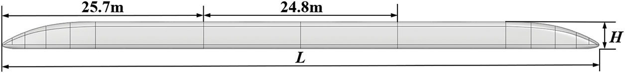
Figure 1: Train geometry model
Fig. 2 shows the computational domain used for the numerical simulation, which measures 400 m in length, 80 m in width, and 40 m in height. The established computational domain satisfies the dimensional criteria mandated by the Chinese Railway Standard TB/T 3503.4-2018, with both the vertical height and upstream extent exceeding 8 times the characteristic length, and the downstream extension reaching at least 16 times the characteristic length. Three refined mesh zones were added near the train to improve accuracy. In this domain, the positive x-direction corresponds to the direction of train motion, and the plane y = 0 represents the train’s symmetry plane. Both the inlet and outlet boundaries are defined as freestream boundaries, with a specified Mach number of 0.49 and an incoming flow direction of (−1, 0, 0). The top and side boundaries are set as symmetry boundary conditions. The ground and track are modeled as slip walls, with their velocity matching that of the incoming flow, Uin = 166.67 m/s, in order to eliminate boundary effects and reduce simulation errors induced by unrealistic wall constraints [28].
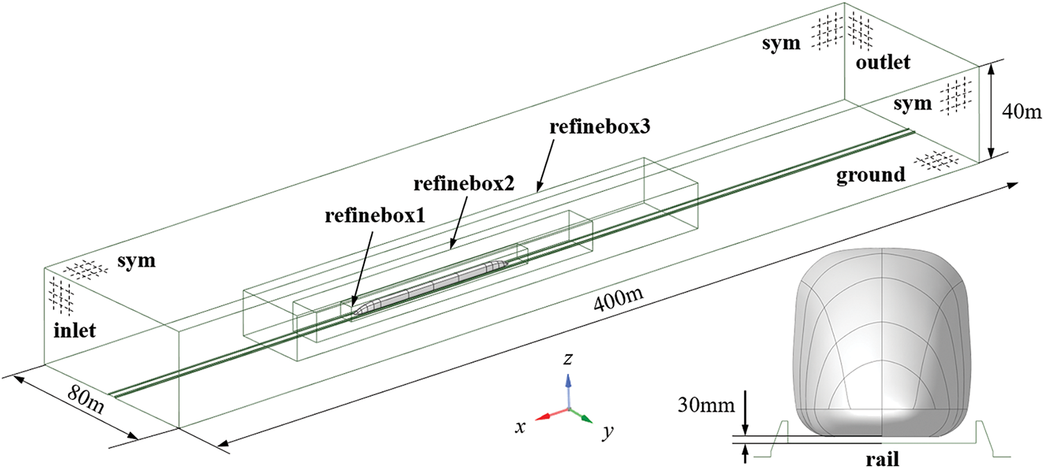
Figure 2: Computational domain model
3 Simulation Method Validation
In order to ensure the calculation accuracy and reliability of the numerical simulation, grid independence test and wind tunnel test verification are first carried out to compare and verify the calculation results.
Three sets of computational grids—coarse, medium, and fine—were generated based on three baseline mesh sizes: 1.1 m, 1.0, and 0.9 mm, respectively. The total number of cells in each mesh is approximately 21.95 million for the coarse grid, 28.41 million for the medium grid, and 34.87 million for the fine grid. All three mesh configurations share identical boundary layer settings. Specifically, the first-layer thickness is set to 0.01 mm, with a total boundary layer thickness of 10 mm distributed over 10 layers. In CFD simulations, y+ helps assess how well the near-wall mesh captures boundary layer flow. For all three grid configurations evaluated, the y+ values on the train surface remain around 1, enabling high-fidelity resolution of boundary layer flow dynamics. A section of the medium grid is illustrated in Fig. 3, highlighting the mesh refinement near the train surface.
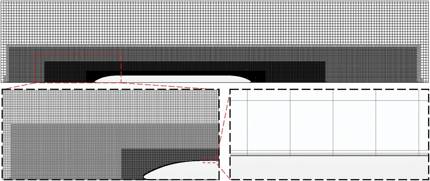
Figure 3: Surrounding mesh and boundary layer mesh of the train
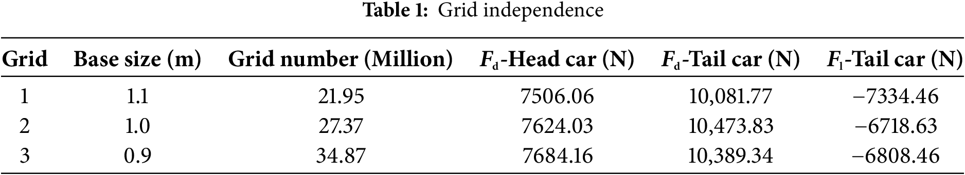
Table 1 presents the aerodynamic forces acting on the train as computed using the three grid configurations. For the drag force on the head car, the relative error between the coarse and medium grids is 1.55%, while the error between the medium and fine grids is 0.79%. For the drag force on the tail car, the relative error between the coarse and medium grids is 3.74%, and between the medium and fine grids is 0.81%. Regarding the lift force on the tail car, the relative error between the coarse and medium grids is 9.17%, whereas the error between the medium and fine grids reduces to 1.34%. These results indicate that the medium grid achieves a good balance between computational cost and solution accuracy, making it suitable for further aerodynamic analysis.
The change in streamlining also significantly affects the flow field in the tail wake region of the train. Therefore, a 20 m-long monitoring line is placed at a cross-section in the tail wake, as shown by the blue solid line in Fig. 4a. Fig. 4b presents the pressure and velocity data corresponding to this monitoring line. The pressure distribution across the three grids in the tail wake is largely consistent, while the velocity distribution shows differences. However, the velocity distributions in the tail wake for the medium grid and the fine grid tend to align. This indicates that the numerical results for the medium grid have stabilized, and the overall results are converging. Considering both computational accuracy and cost, the grid with a baseline size of 1000 mm is selected for the subsequent numerical calculations.
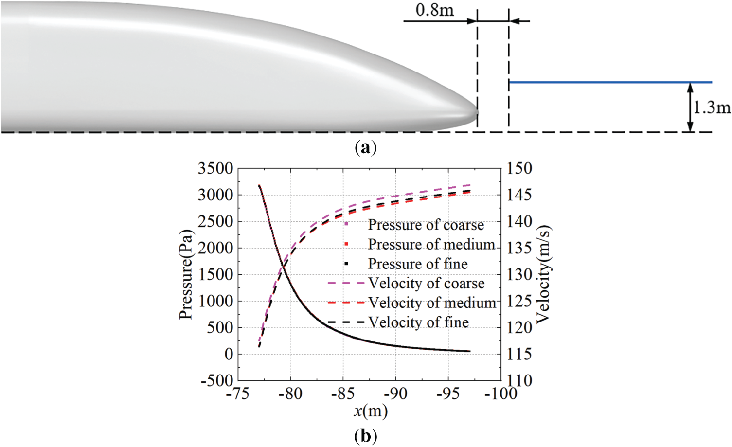
Figure 4: Tail wake grid independence test: (a) Schematic of the monitoring line position, (b) Corresponding pressure and velocity data along the monitoring line
3.2 Wind Tunnel Test Verification
The numerical simulation results are validated through comparison with wind tunnel test data. The wind tunnel experiment employed a 1:8 scaled model of the train, with an incoming flow velocity of 70 m/s, corresponding to a Reynolds number of 2.8 × 10⁶. Scaled train models were built with strict geometric similarity and fixed in the wind tunnel. A multi-stage system creates steady airflow with target speed, density, and pressure. Aerodynamic coefficients of the scaled model are measured during controlled flow conditions using three-dimensional force transducers, thereby enabling extrapolation to full-scale train performance. Complete experimental specifications and validation datasets are documented in the research of Ding et al. [29]. A numerical simulation was conducted using the same flow velocity and scaled train model. The simulation results were then compared with the wind tunnel data. The train model used in the simulation is shown in Fig. 5, with a total length of 81.03 m. The simulation settings are consistent with those described previously, except that the Mach number was adjusted to 0.206.
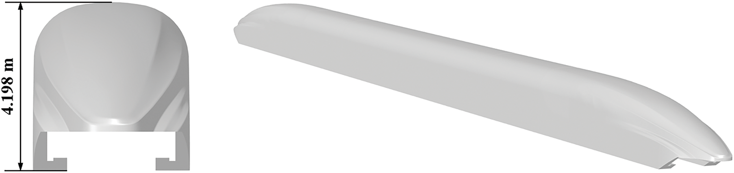
Figure 5: Train geometry model used for numerical verification
The calculation formula of the dimensionless pressure coefficient Cp of high-speed train is as follows.
where P represents the static pressure, P0 is the reference pressure (set as 0 Pa), ρ is the air density (taken as 1.225 kg/m3), and u is the train’s operating speed.
Fig. 6 shows the pressure coefficient distribution on the midsection (y = 0 plane) of the train, based on both numerical simulation and wind tunnel test results. In the figure, the position x = −5 m corresponds to the nose tip of the maglev train’s head car. The numerical simulation results agree well with the experimental data in terms of overall pressure distribution, with measurement point errors all within 10%. In summary, the adopted grid generation strategy and numerical methods can accurately capture the aerodynamic characteristics of high-speed maglev trains.
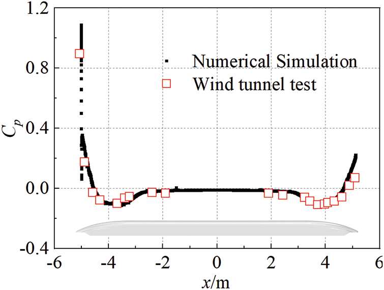
Figure 6: Train geometry model used for numerical verification
Keeping the overall train length constant, the streamlined profiles of the head and tail cars were stretched in 1.2 m increments based on the original model, resulting in six train models with different streamlined lengths, as shown in Fig. 7. Fig. 7a–f corresponds to streamlined lengths of 8.3, 9.5, 10.7, 11.9, 13.1, and 14.3 m, respectively, with Fig. 7d representing the original train configuration.
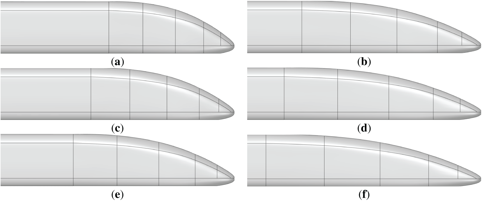
Figure 7: Train models with different streamline lengths: (a) 8.3 m; (b) 9.5 m; (c) 10.7 m; (d) 1.9 m; (e) 13.1 m; (f) 14.3 m
Based on the conclusions from Section 3.1 regarding grid independence verification, the grid for each model is generated using the same settings as the medium grid. Due to the significant geometric changes caused by varying the streamlined length from 8.3 to 14.3 m, the resulting grid sizes range from 25 million to 29 million cells. The computational domain and boundary conditions remain the same as previously defined.
Fig. 8 shows the aerodynamic drag and lift forces of each car for different streamlined lengths. The streamlined length has a significant impact on the aerodynamic performance of the head and tail cars, while the middle cars remain largely unaffected. In Fig. 8a, as the streamlined length increases, the aerodynamic drag of both the head and tail cars gradually decreases. When the streamlined length increases from 8.3 to 14.3 m, the drag on the head car decreases by 16.2%, and that on the tail car decreases by 32.1%. In Fig. 8b, the aerodynamic lift forces on the head and tail cars are negative, indicating a downward force perpendicular to the ground. As the streamlined length increases, the head’s lift drops while the tail’s lift rises. Specifically, when the streamlined length increases from 8.3 to 14.3 m, the magnitude of the negative lift on the head car decreases by 38.2%, while that on the tail car increases from 1524 N to 8978 N. Increasing streamline length reduces drag but also changes lift forces. More lift on the head car may affect levitation balance and reduce suspension stability. Consequently, practical engineering applications must adopt a balanced design approach that carefully considers both the magnitude of aerodynamic lift forces and drag reduction when optimizing the streamlined length for maglev trains.

Figure 8: The aerodynamic force of the train changes with the streamline length: (a) Aerodynamic drag, (b) Aerodynamic lift
Fig. 9 illustrates the friction drag and pressure drag of the three-car train for different streamlined lengths. As shown in the figure, the aerodynamic drag of both the head car and the middle car is predominantly composed of friction drag. As the streamlined length increases, both the friction drag and pressure drag of the head and tail cars decrease. Notably, the pressure drag—which contributes significantly to the overall aerodynamic drag of the tail car—exhibits a larger reduction compared to the friction drag. For the middle car, the pressure drag remains nearly zero, and the friction drag shows minimal change across the different streamlined lengths. The fundamental mechanism behind the more pronounced drag reduction effect in the tail car lies in the streamlined extension’s reconstruction of the wake flow field: By delaying the flow separation point and consequently shifting the formation position of the Kármán vortex street downstream, the reduced scale of trailing vortices facilitates an upstream movement of the pressure recovery zone, thereby effectively decreasing the negative pressure peak at the streamlined section of the tail car.
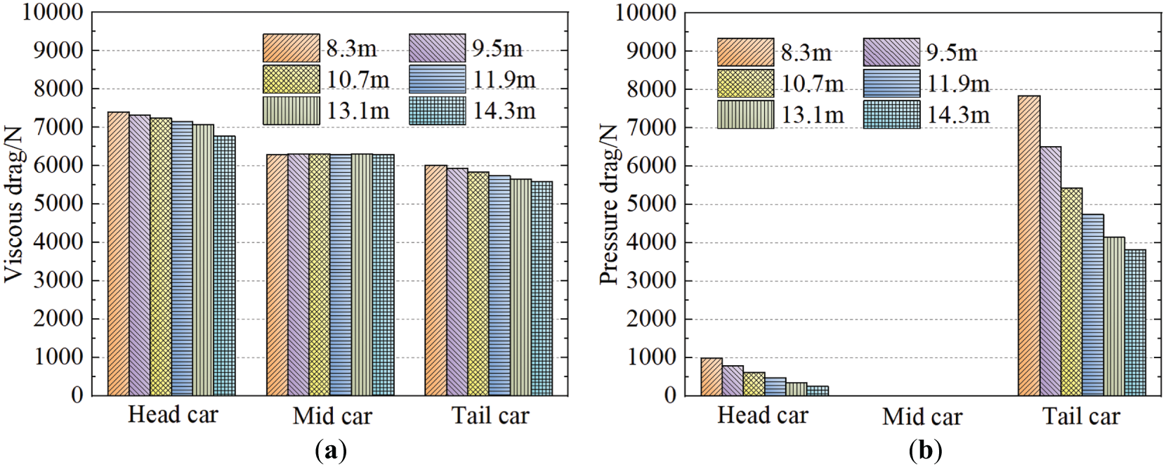
Figure 9: Friction resistance and pressure resistance of each cars: (a) Friction resistance, (b) Pressure resistance
Pressure coefficient distribution on the top mid-section plane (y = 0) for trains with varying streamlined lengths are shown in Fig. 10, where x = 0 corresponds to the nose tip of the maglev train’s head car. The pressure distribution trends on the train surface are generally consistent across all cases. The streamlined sections of the upper surface of the head and tail cars primarily exhibit negative pressure due to flow separation. As the streamlined length increases, the peak values of this negative pressure gradually decrease, indicating an improvement in the aerodynamic behavior and reduced flow separation intensity.
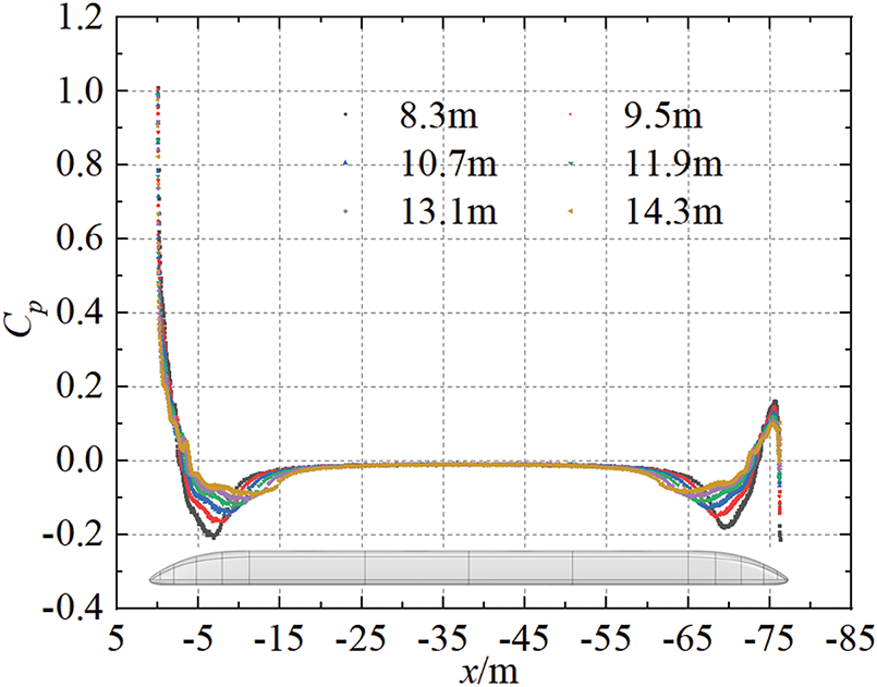
Figure 10: Pressure coefficient distribution on the top mid-section plane for trains with varying streamlined lengths
Fig. 11 shows the surface pressure distribution of the head car for trains with different streamlined lengths. The lower surface of the head car is predominantly under negative pressure, with a significant region of strong negative pressure, which contributes to the downward aerodynamic lift. With increasing streamlined length, the region of positive pressure near the nose tip on the upper surface becomes longer, though the peak pressure magnitude decreases. This change is beneficial in reducing both aerodynamic drag and the magnitude of downward lift on the head car. Moreover, the intensity of negative pressure in the streamlined transition region and on both sides of the streamlined body is clearly reduced. This narrow focus fails to account for the complex interactions among other critical geometric features—including streamline length, height, and longitudinal/horizontal profiles—that collectively influence aerodynamic performance. A longer streamlined section smooths the pressure change and reduces flow separation. Meanwhile, the pressure distribution over the main carbody remains largely unchanged.
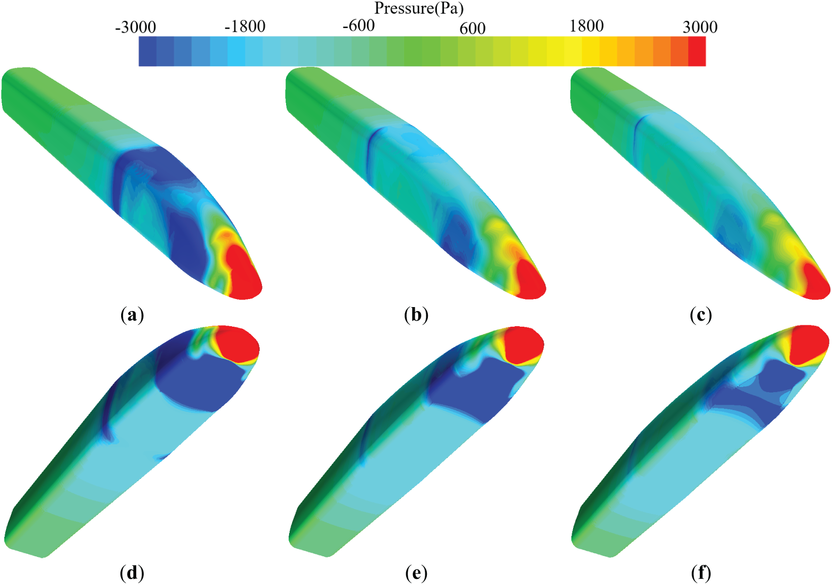
Figure 11: Surface pressure of the head car: (a) 8.3 m-top, (b) 11.9 m-top, (c) 14.3 m-top, (d) 8.3 m-bottom, (e) 11.9 m-bottom, (f) 14.3 m-bottom
Fig. 12 illustrates the surface pressure distribution characteristics of the tail car for different streamlined lengths. Similar to the head car, the lower surface of the tail car generally exhibits negative pressure, with a significant strong negative pressure zone located near the front portion. This region is the primary contributor to the downward aerodynamic lift acting on the tail car. The positive pressure region at the nose tip of the upper surface extends in length, although its intensity diminishes. The negative pressure intensity in the streamlined transition region and along both sides of the streamlined profile also decreases. These combined effects contribute to a reduction in aerodynamic drag on the tail car, while the magnitude of downward lift increases slightly. Additionally, both the area and peak magnitude of the strong negative pressure region on the lower surface tend to decrease. When the streamline length grows from 8.3 to 14.3 m, the tail nose pressure changes from −4171 Pa to +1936 Pa. This reversal indicates a significant improvement in the leading-edge flow behavior due to the extended streamline design. Interestingly, this trend contrasts sharply with the pressure evolution observed at the head car’s nose tip, highlighting a marked difference in aerodynamic interference effects between the head and tail cars resulting from changes in streamlined length.
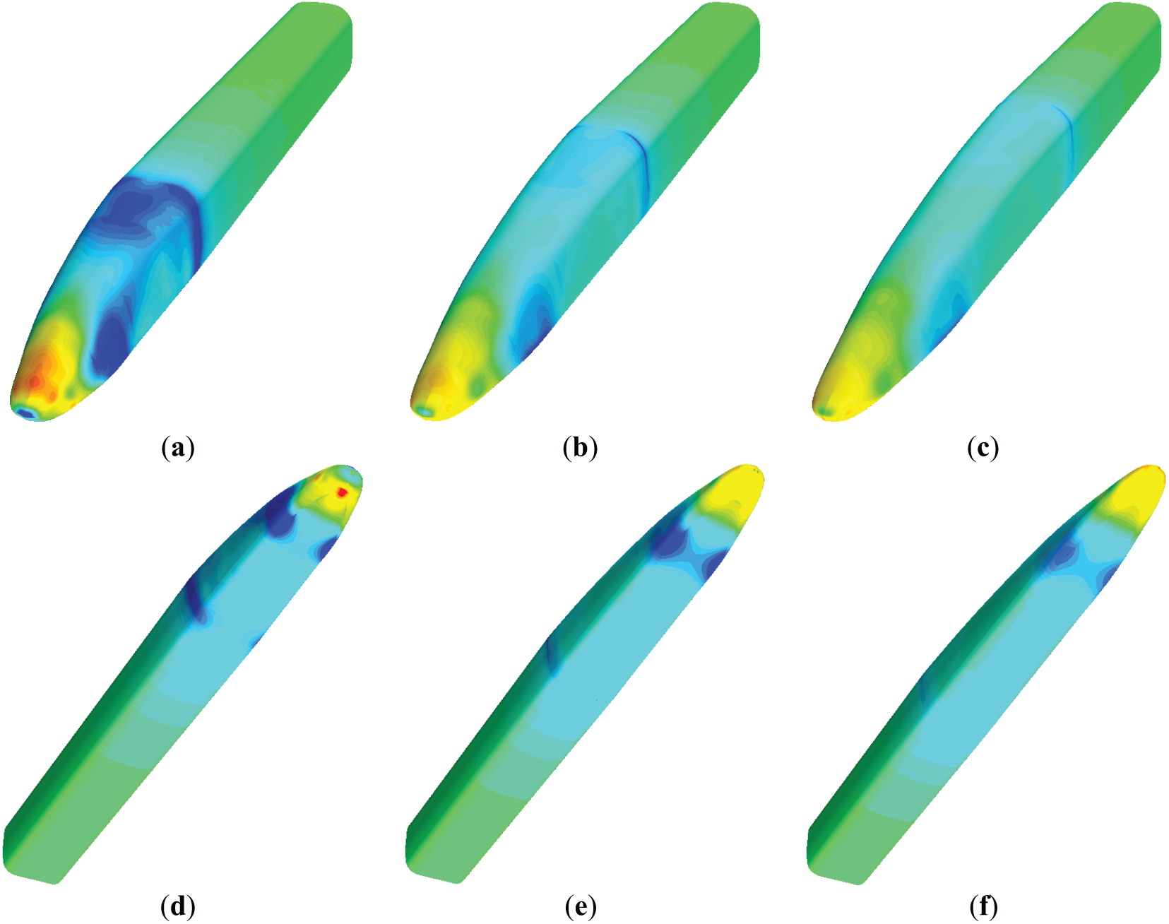
Figure 12: Surface pressure of the tail car: (a) 8.3 m-top, (b) 11.9 m-top, (c) 14.3 m-top, (d) 8.3 m-bottom, (e) 11.9 m-bottom, (f) 14.3 m-bottom
Fig. 13 shows the normalized velocity contour plots at the midsection of the tail car for different streamlined lengths. The variation in streamline length has a significant impact on the flow field around the train. A semicircular high-velocity region is present above the wake. As the streamline length increases, the extent of this semicircular region diminishes, indicating a weakening of the upward flow separation. With the extension of the streamline, the disturbed wake zone progressively shifts closer to the ground, and the low-velocity region behind the tail car gradually shrinks, suggesting improved flow attachment and reduced wake size. Beneath the streamline of the tail car, in the leeward cavity region, a vortex structure forms, characterized by a local low-speed flow area where velocities approach zero. Notably, the size of this low-speed region increases with greater streamline length. These findings suggest that extending the streamline length not only alters the flow structure behind the tail car but also impacts the flow separation and vortex dynamics, especially in the leeward regions.
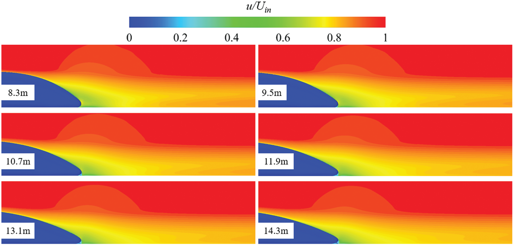
Figure 13: Velocity field of the middle section of the tail car with different streamline lengths
To further explore the influence of streamline length on the train’s wake, a 20 m long monitoring line was set on the y = 0 cross-section behind the tail car, as shown in Fig. 14a. Pressure and velocity data along this monitoring line for different streamline lengths are presented in Fig. 14b,c. The streamline length significantly affects the pressure distribution in the wake. As the streamline length increases, the pressure in the wake decreases, and around 21 m behind the tail car, the wake pressure stabilizes, showing no further significant change. The flow velocity in the wake increases as the streamline length increases. This corresponds to the trend seen in Fig. 13, where the low-speed region behind the tail car gradually diminishes and moves closer to the ground. A longer streamline weakens the wake and speeds up airflow behind the train. These results demonstrate that altering the streamline length not only influences the wake pressure but also significantly affects the velocity distribution, with a reduction in wake turbulence and a closer alignment of the wake to the ground.
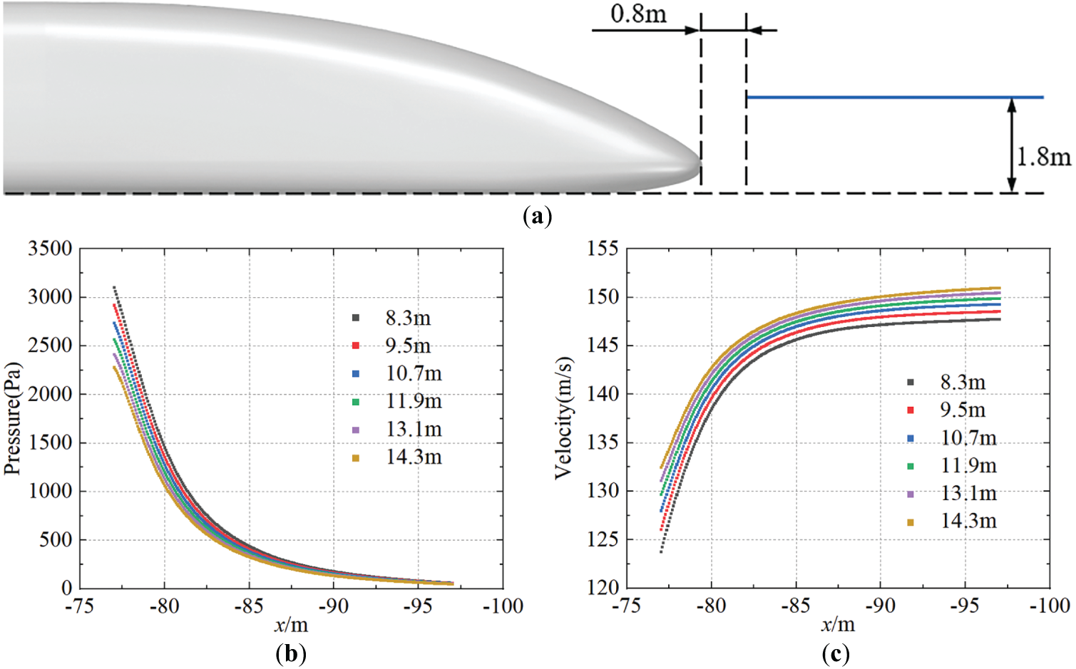
Figure 14: Pressure and velocity distribution on the wake monitoring line: (a) Monitoring line position, (b) Monitoring line pressure, (c) Monitoring line velocity
This paper conducts numerical simulations of a high-speed maglev train with a speed of 600 km/h and a 3-car configuration, investigating the impact of streamline length on the aerodynamic characteristics, surface pressure, and surrounding flow field of the train. The main conclusions are as follows:
(1) The streamline length significantly affects the aerodynamic performance of the head and tail cars of the maglev train, while the middle car remains almost unaffected. As the streamline length increases, the aerodynamic drag of the head and tail cars gradually decreases. Specifically, the head car’s drag decreases by up to 16.2%, and the tail car’s drag decreases by 32.1%. Both friction drag and pressure drag decrease with the increase in streamline length, with the tail car showing a more significant reduction in pressure drag, which is the major contributor to its aerodynamic drag.
(2) The downward lift force on the head car decreases with the increase in streamline length, while the lift force on the tail car increases in the opposite direction. The downward negative lift on the head car decreases by 38.2%, while the negative lift on the tail car increases from 1524 N to 8978 N as the streamline length increases.
(3) As the streamline length increases, the transition of the surface pressure along the streamline becomes smoother. The positive pressure zone at the tip of the head car’s upper surface reduces in intensity, significantly lowering the head car’s drag and the downward negative lift force.
This study shows that a longer streamline reduces drag and improves vertical stability, but it has some key limitations. The primary constraint lies in the simplified single-variable approach, which considers only streamline length as the optimization parameter. Focusing only on length ignores how other shape factors like height and profile also affect aerodynamics. Furthermore, the current methodology’s inability to address coupled aerodynamic effects may lead to suboptimal solutions, as isolated modifications to individual parameters typically yield diminishing returns. These limitations highlight a fundamental gap in our optimization framework, which currently lacks the capacity for comprehensive multi-parameter analysis. Future studies should use integrated optimization that considers all shape variables and their effects on aerodynamics.
Acknowledgement: Not applicable.
Funding Statement: This research was funded by Research and Development Project of JDD For HTS Maglev Transportation System (NO. JDDKYCF2024002), and China National Railway Group Science and Technology Program grant (K2024T005).
Author Contributions: The authors confirm contribution to the paper as follows: Conceptualization, Yan Li and Tian Li; methodology, Yan Li; investigation, Bailong Sun and Tian Li; writing—original draft preparation, Bailong Sun; writing—review and editing, Tian Li; project administration, Yan Li; funding acquisition, Weihua Zhang. All authors reviewed the results and approved the final version of the manuscript.
Availability of Data and Materials: The data presented in this study is available from the corresponding author, upon reasonable request.
Ethics Approval: Not applicable.
Conflicts of Interest: The authors declare no conflicts of interest to report regarding the present study.
References
1. Tian HQ. Review of research on high-speed railway aerodynamics in China. Transp Saf Environ. 2019;1(1):1–21. doi:10.1093/tse/tdz014. [Google Scholar] [CrossRef]
2. Lee HW, Kim KC, Lee J. Review of maglev train technologies. IEEE Trans Magn. 2006;42(7):1917–25. doi:10.1109/TMAG.2006.875842. [Google Scholar] [CrossRef]
3. Li T, Dai ZY, Liu JL, Wu N, Zhang W. Review on aerodynamic drag reduction optimization of high-speed trains in China. J Traffic Transp Eng. 2021;21(1):59. [Google Scholar]
4. Yang MZ, Zhong S, Zhang L, Qian BS, Wang TT, Zhou D, et al. 600 km/h moving model rig for high-speed train aerodynamics. J Wind Eng Ind Aerodyn. 2022;227:105063. doi:10.1016/j.jweia.2022.105063. [Google Scholar] [CrossRef]
5. Yao SB, Guo DL, Sun ZX, Chen DW, Yang GW. Parametric design and optimization of high speed train nose. Optim Eng. 2016;17(3):605–30. doi:10.1007/s11081-015-9298-6. [Google Scholar] [CrossRef]
6. Yamamoto K, Kozuma Y, Tagawa N, Hosaka S, Tsunoda H. Improving maglev vehicle characteristics for the Yamanashi test line. Quart Rep RTRI. 2004;45(1):7–12. doi:10.2219/rtriqr.45.7. [Google Scholar] [CrossRef]
7. Takao S, Mizutani T, Shirakuni N, Kozu M. Vehicle-running tests and development on the Yamanashi maglev test line. Quart Rep RTRI. 2004;45(1):3–6. doi:10.2219/rtriqr.45.3. [Google Scholar] [CrossRef]
8. Zhou D, Wu L, Tan C, Hu TE. Study on the effect of dimple position on drag reduction of high-speed maglev train. Transp Saf Environ. 2021;3(4):tdab027. doi:10.1093/tse/tdab027. [Google Scholar] [CrossRef]
9. Meng S, Zhou D, Tan C. The effect of concave size on the aerodynamics of a maglev train. J Bionic Eng. 2022;19(3):709–23. doi:10.1007/s42235-022-00158-4. [Google Scholar] [CrossRef]
10. Li HC, Yang ZM, Zhang L, Li R. Adjoint optimization method for head shape of high-speed maglev train. J Appl Fluid Mech. 2021;14(6):1839–50. doi:10.47176/jafm.14.06.32227. [Google Scholar] [PubMed] [CrossRef]
11. Sun ZX, Wang MY, Wei LY, Kong FB, Yang GW. Aerodynamic shape optimization of an urban maglev train. Acta Mech Sin. 2021;37(6):954–69. doi:10.1007/s10409-021-01094-y. [Google Scholar] [CrossRef]
12. Yang X, Jin J, Shi G. Preliminary study on streamlined design of longitudinal profile of high-speed train head shape. Procedia Soc Behav Sci. 2013;96:1469–76. doi:10.1016/j.sbspro.2013.08.167. [Google Scholar] [CrossRef]
13. Deng E, Liu XY, Ouyang DH, Yue H, Ni YQ. 3D ultrasonic anemometer array reveals jet flow structures at the entrance of high-speed railway tunnel. J Wind Eng Ind Aerodyn. 2025;257:106004. doi:10.1016/j.jweia.2024.106004. [Google Scholar] [CrossRef]
14. Liu H, Yu Q, Li Y, Zhang Y, Peng K, Kong Z, et al. Quantification analysis of high-speed train aerodynamics with geometric uncertainty of streamlined shape. Int J Numer Meth Heat Fluid Flow. 2024;34:109096. doi:10.1108/hff-06-2024-0454. [Google Scholar] [CrossRef]
15. He P, Zhang J, Zhang L, Wang J, Ma Y. Influence of anteroposterior symmetrical aero-wings on the aerodynamic performance of high-speed train. Comput Model Eng Sci. 2024;139(1):937–53. doi:10.32604/cmes.2023.043700. [Google Scholar] [CrossRef]
16. Dai Z, Li T, Zhang W, Zhang J. Research progress of aerodynamic multi-objective optimization on high-speed train nose shape. Comput Model Eng Sci. 2023;137(2):1461–89. doi:10.32604/cmes.2023.028677. [Google Scholar] [CrossRef]
17. Yao S, Guo D, Sun Z, Yang G, Chen D. Multi-objective optimization of the streamlined head of high-speed trains based on the Kriging model. Sci China Technol Sci. 2012;55(12):3495–509. doi:10.1007/s11431-012-5038-8. [Google Scholar] [CrossRef]
18. Zhang L, Zhang JY, Li T, Zhang YD. Multi-objective aerodynamic optimization design of high-speed train head shape. J Zhejiang Univ Sci A. 2017;18(11):841–54. doi:10.1631/jzus.a1600764. [Google Scholar] [CrossRef]
19. Zhang Y, Yang G, Sun Z, Guo DL. A general shape optimization method based on FFD approach with application to a high-speed train. J Multidiscip Eng Sci Technol. 2016;3(12):6181–8. [Google Scholar]
20. He Z, Liu T, Liu H. Improved particle swarm optimization algorithms for aerodynamic shape optimization of high-speed train. Adv Eng Softw. 2022;173:103242. doi:10.1016/j.advengsoft.2022.103242. [Google Scholar] [CrossRef]
21. Sun Z, Song J, An Y. Optimization of the head shape of the CRH3 high speed train. Sci China Technol Sci. 2010;53(12):3356–64. doi:10.1007/s11431-010-4163-5. [Google Scholar] [CrossRef]
22. Xu G, Liang X, Yao S, Chen D, Li Z. Multi-objective aerodynamic optimization of the streamlined shape of high-speed trains based on the Kriging model. PLoS One. 2017;12(1):e0170803. doi:10.1371/journal.pone.0170803. [Google Scholar] [PubMed] [CrossRef]
23. Mughal KH, Bugvi SA, Jamil MF, Baig BT, Ahmad T, Irfan M, et al. Enhancement of aerodynamic performance of high speed train through nose profile design: a computational fluid dynamics approach. J Kejuruter. 2022;34(6):1237–50. doi:10.17576/jkukm-2022-34(6)-24. [Google Scholar] [CrossRef]
24. Muñoz-Paniagua J, García J, Crespo A. Genetically aerodynamic optimization of the nose shape of a high-speed train entering a tunnel. J Wind Eng Ind Aerodyn. 2014;130:48–61. doi:10.1016/j.jweia.2014.03.005. [Google Scholar] [CrossRef]
25. Munoz-Paniagua J, de Madrid UP, Garcia J, de Madrid UP, Crespo A, de Madrid UP, et al. Aerodynamic optimization of the nose shape of a train using the adjoint method. J Appl Fluid Mech. 2015;8(3):601–12. doi:10.18869/acadpub.jafm.67.222.22632. [Google Scholar] [CrossRef]
26. Wang Y, Sun Z, Ju S, Guo D, Yang G. Robust optimisation of the streamlined shape of a high-speed train in crosswind conditions. Eng Appl Comput Fluid Mech. 2023;17:2234012. doi:10.1080/19942060.2023.2234012. [Google Scholar] [CrossRef]
27. Li T, Hemida H, Zhang J, Rashidi M, Flynn D. Comparisons of shear stress transport and detached eddy simulations of the flow around trains. J Fluids Eng. 2018;140(11):111108. doi:10.1115/1.4040672. [Google Scholar] [CrossRef]
28. Li Y, Li T, Zhang J. Mitigation of abnormal vibration on high-speed trains under unsteady aerodynamic loadings using bogie skirts. Phys Fluids. 2025;37:015137. doi:10.1063/5.0244409. [Google Scholar] [CrossRef]
29. Ding S, Yao S, Chen D. Aerodynamic lift force of high-speed maglev train. J Mech Eng. 2020;56(8):228. doi:10.3901/jme.2020.08.228. [Google Scholar] [CrossRef]
Cite This Article
 Copyright © 2025 The Author(s). Published by Tech Science Press.
This work is licensed under a Creative Commons Attribution 4.0 International License , which permits unrestricted use, distribution, and reproduction in any medium, provided the original work is properly cited.
 Downloads
 Citation Tools