
 Submit a Paper
 Propose a Special lssue
 Open Access
ARTICLE

Integrating Carbonation Durability and Cover Scaling into Low-Carbon Concrete Design: A New Framework for Sustainable Slag-Based Mixtures
1 Department of Integrated Energy and Infra System, Kangwon National University, Chuncheon-si, 24341, Republic of Korea
2 School of Qilu Transportation, Shandong University, Jinan, 250002, China
3 Yunnan Key Laboratory of Disaster Reduction in Civil Engineering, Faculty of Civil Engineering and Mechanics, Kunming University of Science and Technology, Kunming, 650500, China
4 Research Group RecyCon, Department of Civil Engineering, KU Leuven, Campus Bruges, Bruges, 8200, Belgium
5 Department of Architectural Engineering, Kangwon National University, Chuncheon-si, 24341, Republic of Korea
* Corresponding Authors: Runsheng Lin. Email: ; Xiao-Yong Wang. Email:
(This article belongs to the Special Issue: Advanced Modeling and Simulation for Sustainable Construction Materials and Structures)
Computer Modeling in Engineering & Sciences 2026, 146(1), 13 https://doi.org/10.32604/cmes.2025.074787
Received 17 October 2025; Accepted 12 December 2025; Issue published 29 January 2026
 View Full Text
 Download PDF
Abstract
Conventional low-carbon concrete design approaches have often overlooked carbonation durability and the progressive loss of cover caused by surface scaling, both of which can increase the long-term risk of reinforcement corrosion. To address these limitations, this study proposes an improved design framework for low-carbon slag concrete that simultaneously incorporates carbonation durability and cover scaling effects into the mix proportioning process. Based on experimental data, a linear predictive model was developed to estimate the 28-day compressive strength of slag concrete, achieving a correlation coefficient of R = 0.87711 and a root mean square error (RMSE) of 7.55 MPa. The mechanism-based equation exhibits strong physical interpretability, as each parameter corresponds to a clear physical process, satisfying the requirements of design codes for physical significance. By integrating the strength and carbon-emission models, the carbon-emission efficiency was further analyzed. Across all water–binder ratios (0.3, 0.4, 0.5), CO2 emissions per unit strength decreased steadily with increasing slag content, indicating that carbon efficiency is primarily governed by slag replacement rather than the water/binder ratio. Four design cases, all with a design strength of 30 MPa, were then evaluated to illustrate the combined effects of carbonation and scaling. In Case 1, without considering carbonation durability, the carbonation depth after 50 years exceeded the 25 mm cover, leading to potential corrosion. In Case 2, when carbonation durability was considered, the required actual strength increased to 31.28 MPa. When mild cover scaling of 3 mm was introduced (Case 3), the required strength rose to 34.59 MPa, and under severe scaling of 10 mm (Case 4), it increased to 45.73 MPa. These results indicate that intensified scaling demands higher strength and lower water/binder ratios to maintain durability. Overall, the proposed framework quantitatively balances strength, durability, and embodied carbon, supporting sustainable low-carbon concrete design.Keywords
Developing low-carbon concrete is crucial for mitigating greenhouse gas emissions in the construction sector, as the production of ordinary Portland cement alone contributes approximately 7%–8% of global CO2 emissions [1,2]. One effective approach is the use of slag to partially replace cement, which can significantly lower carbon emissions while maintaining or even improving compressive strength and long-term performance. As urbanization continues, incorporating slag and other supplementary cementitious materials into concrete mix design has become a key strategy for achieving sustainable, low-carbon infrastructure that balances environmental responsibility with structural reliability [3,4].
Recent advances in low-carbon concrete mix design reveal a clear shift toward intelligent, data-driven, and multi-objective optimization strategies. DeRousseau et al. [5] highlighted the transition from empirical mix design to data-driven, Artificial Intelligence (AI)-based multi-objective frameworks in sustainable concrete research. Building on computational intelligence, Mahjoubi et al. [6] introduced an automated machine learning and multi-objective optimization framework for strain-hardening cementitious composites (SHCC), integrating Tree-based pipeline optimization tool (TPOT), Non-dominated Sorting Genetic Algorithm III(NSGA-III), and Technique for Order of Preference by Similarity to Ideal Solution (TOPSIS) to balance strength, cost, and environmental impact. Shobeiri et al. [7] applied AI-driven genetic algorithms with life-cycle assessment to optimize fly ash–slag concretes, achieving up to 60% lower global warming potential (GWP) and 40% cost savings without sacrificing strength. Fan et al. [8] coupled gradient boosting and Non-dominated Sorting Genetic Algorithm II (NSGA-II) to optimize recycled aggregate concrete, identifying cement and water as key variables. Zhang et al. [9] combined machine learning with multi-objective particle swarm optimization (MOPSO) to generate Pareto-optimal solutions for strength, slump, and cost. Wu et al. (2023) [10] advanced the field through a Bayesian-optimized machine-learning model with near-perfect predictive accuracy (R² ≈ 0.99). Peng et al. [11] developed a data-driven intelligent design framework that integrates hybrid machine learning models with multi-objective optimization to accurately predict and optimize the workability, strength, durability, carbon emissions, and cost of recycled-aggregate concrete incorporating composite cementitious materials, thereby enabling systematic design of green and low-carbon concrete. Collectively, these studies underscore an emerging paradigm in low-carbon concrete design characterized by machine-learning-based property prediction, multi-objective optimization algorithms (such as NSGA-II and MOPSO), and the establishment of systematic, generalizable frameworks that simultaneously optimize strength, cost, and environmental performance.
Although AI-based low-carbon concrete mix design has achieved significant progress, several key limitations still hinder its practical and long-term application. First, even when slag concrete and Portland concrete reach the same 28-day strength, slag concrete shows lower carbonation resistance [12,13]. Most current optimization studies have focused on reducing cement usage, material cost, or embodied CO2, and a variety of data-driven and computational approaches have been proposed to achieve these goals [5,6]. Subsequent studies further refined these frameworks and demonstrated their applicability in multi-objective mixture optimization [7,8]. However, despite these valuable contributions, carbonation durability has seldom been incorporated as a design objective, leaving this critical long-term performance indicator largely underexplored [9,10]. As carbonation decreases alkalinity, it promotes steel corrosion, cracking, and stiffness loss, ultimately undermining the long-term sustainability of reinforced concrete. Although recent optimization studies have advanced mixture design from the perspectives of cost, CO2 reduction, and mechanical performance [5–7], they seldom incorporate realistic degradation of the concrete cover—such as carbonation-induced corrosion—into their design frameworks [8–10]. In practice, freeze–thaw cycles, corrosion pressure, thermal stress, acid rain, and insufficient curing effects accelerate cover scaling and cracking, and increasing corrosion risk. Third, although AI models exhibit strong predictive ability, many lack interpretability, functioning as “black boxes” that obscure physical mechanisms [14]. This reduces trust in predictions and may cause bias or overfitting under new conditions. Compared with artificial intelligence methods that lack clear physical mechanisms, current design codes tend to adopt mechanism-based equations to predict various material properties, such as compressive strength and carbonation depth [15].
To overcome the limitations of existing low-carbon concrete mix design methods—particularly the neglect of carbonation durability and cover depth scaling loss—this study proposes a new optimization methodology for low-carbon slag concrete. The proposed framework aims to minimize the CO2 emissions of the binder materials while ensuring that the designed concrete satisfies the required constraints of compressive strength and carbonation durability. The optimization process is implemented using the genetic algorithm (GA) module in MATLAB [16], which iteratively searches for the optimal combination of slag content and cement content that achieves the lowest carbon footprint. Four design cases were established to evaluate the proposed method under increasing environmental severity. Case 1 met the strength requirement with minimal binder-related CO2 emissions. Case 2 incorporated carbonation resistance with constant cover. Case 3 considered mild cover loss of 3 mm [17], while Case 4 simulated severe cover loss of 10 mm [17]. In all cases, CO2 emissions were minimized while ensuring both strength and durability, allowing a stepwise assessment of sustainability under different exposure conditions.
The originality of this study can be summarized as follows: (1) It incorporates carbonation durability into the optimization framework for low-carbon slag concrete, directly minimizing CO2 emissions from the binder system while ensuring adequate resistance to carbonation, thereby linking sustainability with long-term structural performance. (2) It explicitly considers concrete cover scaling as a degradation mechanism influenced by environmental factors. By coupling the MATLAB-based genetic algorithm with service-life modeling, the method realistically reflects the impact of cover loss on carbonation depth and service life. (3) The proposed optimization design platform has a clear mechanistic foundation and consists of two main components: a property prediction module and an optimization module. The property prediction module employs mechanism-based equations to estimate CO2 emissions, compressive strength, carbonation depth, and the effective cover thickness (defined as the initial cover thickness minus the scaled layer). The optimization module is implemented using MATLAB’s Optimization Toolbox. This platform can be easily adapted to different design scenarios, making it convenient for use and further development by other researchers.
The model design process is structured as a constraint-based optimization framework that integrates mechanical, carbonation durability, and workability requirements to achieve a sustainable low-carbon slag concrete mix. As shown in Fig. 1, the flow of optimal design is shown as follows:
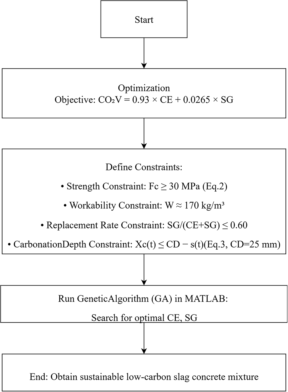
Figure 1: Flowchart of optimal design
(1) Optimization Objective: The optimization objective of this study is to minimize the total CO2 emissions generated by the binder system while maintaining the required mechanical and carbonation durability performance of the concrete. Since cement production is the primary contributor to carbon emissions, the model aims to reduce cement content and increase the proportion of slag, which has a much lower emission intensity. The CO2 emissions of the binder system are calculated using Eq. (1):
where CO2V represents the total CO2 emissions (kg CO2/kg binder), CE is the mass of cement (kg/m3), and SG is the mass of slag (kg/m3). The emission factors 0.93 and 0.0265 correspond to the carbon emission coefficients of cement and slag, respectively, derived from life-cycle assessment data [18]. Carbon emissions from cement and slag may differ depending on the production method. The carbon emissions in Eq. (1) need to be adjusted according to the production method of the cementitious materials.
(2) Strength Constraint: The strength constraint is introduced to ensure that the optimized low-carbon slag concrete maintains sufficient mechanical performance for structural applications. Specifically, the 28-day compressive strength of the designed mixture must not fall below the target design strength, thereby guaranteeing load-bearing capacity and overall structural safety. This requirement prevents the optimization process from excessively reducing cement content for the sake of lowering CO2 emissions at the expense of mechanical reliability. The constraint is mathematically expressed as:
where Fc denotes the compressive strength of the concrete at 28 days. The formula for calculating the 28-day compressive strength (Fc) was derived through regression analysis based on experimental results. The threshold value of 30 MPa corresponds to the typical design strength used in carbonation environmental concrete [15,19], ensuring that the optimized low-carbon mixture remains suitable for practical engineering applications. This constraint thus serves as a key boundary condition balancing environmental sustainability with essential performance requirements.
(3) Workability Constraint: The workability requirement is addressed by regulating the amount of mixing water. Based on previous research, for structural concrete using coarse aggregates with a maximum size of 20–25 mm, a water content of about 170 kg per cubic meter is typically adequate to ensure satisfactory workability [20]. It should be emphasized, however, that concrete workability is influenced by multiple interacting factors, and adopting a constant unit water content represents a simplified assumption. Future studies should incorporate more advanced, mechanism-based models to predict and evaluate concrete workability with higher accuracy. In addition, with the development of modern concrete technology, water-reducing agents are widely used in the manufacture of high-performance concrete. Water-reducing agents are also one of the factors affecting the workability of concrete.
(4) Replacement Rate Constraint: In this study, the replacement rate of slag in the binder is defined as the ratio of slag to the total binder content, expressed as SG/(CE + SG). To maintain sufficient hydration activity, this ratio should not exceed 0.60 [21]. This upper limit ensures that while the cement content is effectively reduced to lower CO2 emissions, the optimized mixture still retains adequate strength development.
(5) Carbonation Depth Constraint: The carbonation depth constraint ensures that the predicted carbonation front does not reach the reinforcing steel during the service life, thereby maintaining long-term carbonation durability and corrosion protection. This requirement is expressed as:
where Xc(t) denotes the carbonation depth at time t, CD represents the initial thickness of the concrete cover over the reinforcement, and s(t) is scaling depth of the cover. The right-hand term (CD − s(t)) defines the effective cover thickness after accounting for time-dependent surface loss due to environmental degradation. In this study, following the recommendations of concrete carbonation durability design codes, the nominal cover depth CD is taken as 25 mm [15,19]. The parameter s(t) varies with environmental exposure conditions, reflecting the rate of cover depth deterioration caused by load and environmental factors [17]. This constraint ensures that even under progressive scaling, the reinforcement remains protected from carbonation-induced corrosion throughout the service life of the structure. In this study, carbonation durability and carbonation resistance are both used to describe carbonation-related properties of concrete, and the two are closely related. The stronger the carbonation resistance of concrete, the lower its carbonation depth and the better its carbonation durability. Carbonation durability was evaluated using Eq. (3), requiring that the calculated carbonation depth does not exceed the remaining protective cover thickness (initial cover minus scaling depth).
(6) Finally, the genetic algorithm (GA) in MATLAB [16] performs the optimization by minimizing CO2 emissions under the above constraints, efficiently searching for the optimal combination of slag content and cement content. This framework provides a practical and reliable approach for designing low-carbon, durable, and workable slag concretes.
3 Strength Equation and CO2 Emissions Analysis
3.1 Compressive Strength Equation
For ordinary Portland cement concrete, the 28-day compressive strength mainly depends on the water-to-cement ratio, showing an approximately linear relationship with the cement-to-water mass ratio. In contrast, for slag-blended Portland cement concrete, the 28-day strength is influenced by both the cement-to-water and slag-to-water mass ratios. Yeh conducted extensive experiments on compressive strength and also collected strength test results from many other researchers, thereby establishing a comprehensive compressive strength dataset. The dataset used in this study is publicly available at https://archive.ics.uci.edu/dataset/165/concrete+compressive+strength [22]. Considering the diversity and breadth of the data sources, the authors regarded the 28-day strength model as reliable. Moreover, this dataset has been widely utilized by researchers worldwide, further demonstrating the credibility and reliability of the experimental results [22]. By explicitly addressing both carbonation durability and cover-related deterioration, the present study fills this critical research gap. Therefore, the present study also adopts Yeh’s dataset, which has been widely used in data-driven mixture design research [5,6]. However, previous studies relying on this dataset primarily focused on predicting mechanical properties or optimizing mixture compositions and did not incorporate carbonation durability into their modeling frameworks [7,8]. Moreover, they overlooked the deterioration of carbonation resistance caused by surface cover scaling, a mechanism that significantly accelerates CO2 ingress and reinforces long-term degradation [9,10]. The experimental conditions are summarized as follows [21]. Cylindrical specimens with a diameter of 10 cm and a height of 20 cm were used for compressive strength testing. Each specimen was moist-cured for 24 h, demolded, and then water-cured at 25°C until the testing age. The reported strength values represent the average of five specimens. Although the original experiments covered curing ages from 3 to 365 days, this study focuses exclusively on the 28-day compressive strength results. The coarse aggregate was crushed natural rock, and the fine aggregate was washed river sand. The binder consisted of American Society for Testing and Materials (ASTM) Type I Portland cement and water-quenched ground granulated blast-furnace slag supplied by a steel manufacturer. Ordinary tap water was used for mixing. From regression analysis of these data, an empirical formula was established to predict the 28-day compressive strength as follows:
In Eq. (4), WT is the mass of water in concrete. In Eq. (4), the coefficient of CE/WT (21.41) is greater than that of SG/WT (17.27), indicating that per unit mass, cement contributes more to strength than slag does, which is consistent with engineering practice [3].
The Fig. 2 presents the correlation between estimated and experimental compressive strength results for 208 data pairs: the x-axis shows the model’s evaluation results (MPa), the y-axis shows experimental test results (MPa), and each blue square represents one predicted–measured pair, plotted against a dashed y = x line denoting perfect agreement. The data cluster closely around this line, indicating strong predictive performance, with a correlation coefficient (R = 0.87711) and a root mean square error (RMSE) of 7.5512 MPa; overall, the model provides reliable strength predictions with high correlation and acceptable error.
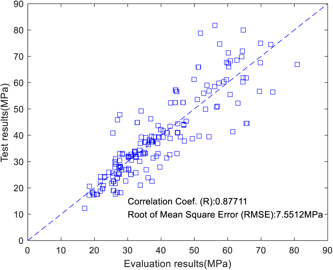
Figure 2: Estimated and experimental compressive strength
The main advantage of the mechanism-based strength Eq. (4) is its strong physical interpretability—each parameter corresponds to a clear physical process, allowing researchers to understand how material composition and environmental factors influence strength development. The main limitation is their limited predictive accuracy, as simplified formulations cannot fully capture the complex nonlinear interactions among multiple variables compared with data-driven machine-learning models. In summary, compared with AI methods lacking clear mechanisms, current design codes prefer mechanism-based Equations to predict strength [15].
Fig. 3a shows CO2 emissions (kg/m3) for 1 m3 of concrete vs. slag replacement ratio (0–0.6) at three water-to-binder ratios (w/b = 0.5, 0.4, 0.3). Emissions decrease steadily as slag content increases for every w/b; at a fixed slag level, mixes with the lower w/b (0.3) generally emit more CO2 because they require more binder to achieve workability and strength. At 60% slag, emissions drop markedly relative to the no-slag case, underscoring the environmental benefit of slag substitution. Overall, the lowest per-m3 emissions are achieved by combining high slag replacement with a higher w/b.
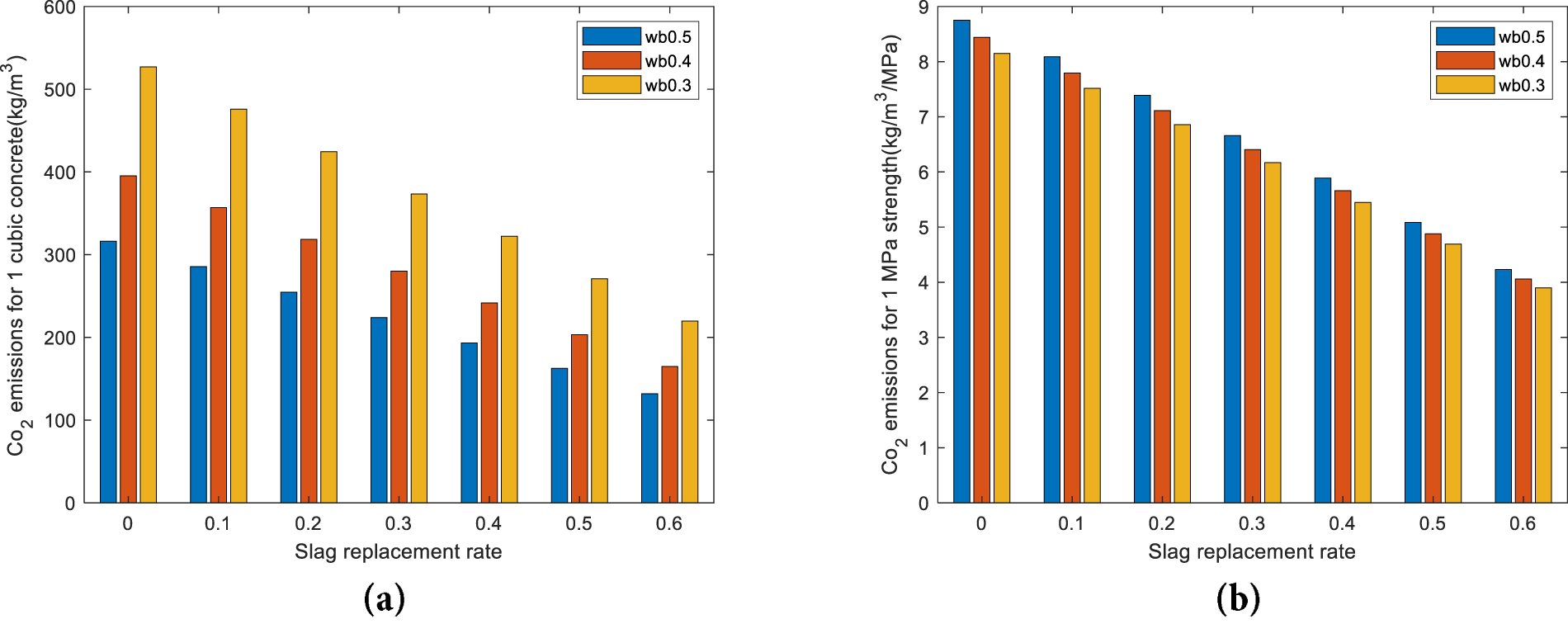
Figure 3: CO2 emission analysis. (a) CO2 emissions (kg/m3) for 1 m3 of concrete. (b) carbon emissions per unit strength
In addition to carbon emissions per unit volume, carbon emissions per unit strength (carbon emission efficiency) is also an important indicator of sustainability. CO2 Emission Efficiency can be calculated as follows:
In Eq. (5), CO2F represents the CO2 emissions per unit compressive strength, which reflects the carbon efficiency of the concrete mixture. A lower value of CO2F indicates that less CO2 is emitted to achieve a given level of strength, signifying a more environmentally efficient and sustainable concrete mix.
Fig. 3b plots CO2 emissions Efficiency (kg/m3·MPa) against slag replacement ratio (0–0.6) for mixes with w/b = 0.5, 0.4, and 0.3. Across all water–binder ratios, the CO2 per MPa decreases monotonically as slag content increases, and the gaps between the three w/b curves are relatively small—indicating that carbon efficiency (CO2 per strength) is driven more by slag substitution than by w/b. At 60% slag, the emissions per MPa fall to about half of the pure-cement case, showing that replacing cement with slag not only lowers total embodied CO2 but also makes strength production markedly more carbon-efficient.
4 Carbonation Depth Calculation Equation
When slag-containing concrete and ordinary Portland cement (OPC) concrete have the same strength, slag concrete has a stronger resistance to chloride ion attack, but weaker carbonation durability [12,13]. In the design of slag concrete, strength alone cannot guarantee carbonation durability; it must be considered as an additional constraint.
Concrete carbonation is a complex physical and chemical process. Many models for calculating carbonation depth have been proposed by researchers worldwide. The Papadakis model is one of the most widely used. This model systematically considers the effects of ambient humidity, temperature, and the concrete material on carbonation depth. According to the research by Papadakis and Tsimas [12,23,24], the equation for calculating carbonation depth is as follows:
In Eq. (6), the term D in the numerator denotes the diffusion coefficient of CO2, while [CO2]0 indicates the ambient CO2 concentration. The denominator
First, how to extend the applicability range of the carbonation depth equation with respect to relative humidity. Papadakis et al. [27] measured the carbonation depth of concrete under different relative humidity conditions and found that the influence of relative humidity on carbonation depth approximately follows a parabolic relationship. When the relative humidity is 0.5, the carbonation depth reaches its maximum, and this value can be regarded as the symmetry axis of the parabola. When the relative humidity is greater than 0.5, CO2 diffusion dominates the carbonation process, and the carbonation depth can be calculated using the Eq. (7) used in this study. When the relative humidity is less than 0.5, the carbonation depth can be estimated using a symmetric approach. The calculation involves two steps. First, convert the relative humidity using the relation RH_eq = 1 − RH. For example, when RH = 0.1, 0.2, 0.3, and 0.4, the equivalent relative humidities are 0.9, 0.8, 0.7, and 0.6, respectively [27]. Second, use the converted relative humidity to calculate the carbonation depth. Overall, to extend the applicable range of carbonation depth calculation, the relative humidity in Eq. (7) can be empirically expressed as a piecewise function as follows.
this piecewise function is continuous at RH = 0.5.
Second, how to consider time-dependent environmental conditions. According to meteorological records, annual variations in temperature and humidity may occur. To account for climate change, the carbonation equation can be expressed in an incremental form. The total service period is divided into many small-time steps, within which temperature and humidity are assumed constant. The total carbonation depth is then obtained by summing the incremental depths for all time steps.
Third, how to consider the reaction degree of the binder. The carbonation depth equation also accounts for the influence of binder reaction level
Fourth, according to reference [24], the predicted carbonation depths obtained from this model show good agreement with experimental measurements, which include both accelerated carbonation tests under laboratory conditions and natural carbonation tests under field exposure, with carbonation durations ranging from 1 to 70 years. These results demonstrate that the adopted equation accurately reflects the influence of real environmental conditions on carbonation depth development.
Finally, how to consider the influence of surface scaling on carbonation depth. In the context of carbonation, concrete can be conceptually divided into a carbonated zone and a non-carbonated zone. At the interface between these two zones lies the CO2 diffusion front, where the CO2 concentration equals that of the surrounding environment [24]. When surface scaling of the concrete cover occurs, the newly exposed surface is also subjected to the same ambient CO2 concentration. Therefore, the boundary condition after scaling remains consistent with the assumption used in the carbonation depth calculation model.
A parametric study of carbonation depth was performed using Eqs. (6) and (7) to clarify how the water-to-binder ratio and slag content influence carbonation behavior. In this analysis, the CO2 concentration was set to 0.04%, temperature to 278 K, relative humidity to 0.6, and the unit water content (WT) to 170. The CO2 concentration of 0.04% reflects current atmospheric conditions [24]. The temperature was set to 278 K (5°C) rather than the standard 293 K (20°C) because surface scaling of concrete is primarily associated with frost-induced deterioration [29]. A relative humidity of 0.6 was selected since carbonation progresses most rapidly at intermediate humidity levels (0.5–0.7): higher humidity saturates capillary pores and restricts CO2 diffusion, whereas lower humidity limits the reaction between CO2 and carbonatable solids [24]. The unit water content was determined based on the workability requirements of the concrete mixture [20].
The Fig. 4a shows the predicted carbonation depth of concrete over a 50-year period for mixes with a water-to-binder mass ratio of 0.5 (wb50) and varying slag contents: wb50-sg0 (0% slag) reaches 18.45 mm at 50 years, wb50-sg30 (30% slag) reaches 21.41 mm, and wb50-sg60 (60% slag) reaches 25.11 mm. Carbonation depth increases with both service time and slag replacement ratio; after 50 years the no-slag mix has the smallest depth and the 60%-slag mix the largest. This trend indicates that, although slag can reduce CO2 emissions and improve sustainability, it tends to increase carbonation susceptibility because the binder contains less portlandite and has lower alkalinity [28].
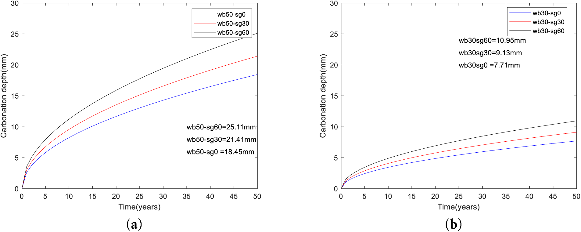
Figure 4: Effects of slag contents on carbonation depth (a) carbonation depth of a water/binder mass ratio 0.5. (b) carbonation depth of a water/binder mass ratio 0.3
The Fig. 4b presents the predicted carbonation depth of concrete over 50 years for mixes with a water-to-binder mass ratio of 0.3 (wb30) and varying slag contents: wb30-sg0 (0% slag) reaches 7.71 mm, wb30-sg30 (30% slag) reaches 9.13 mm, and wb30-sg60 (60% slag) reaches 10.95 mm at 50 years.
Summarily, for a given slag replacement ratio, reducing the water-to-binder mass ratio significantly lowers carbonation depth. Comparing w/b = 0.5 to w/b = 0.3 at 50 years: with 0% slag, depth drops from 18.45 to 7.71 mm (≈58% reduction); with 30% slag, from 21.41 to 9.13 mm (≈57% reduction); with 60% slag, from 25.11 to 10.95 mm (≈56% reduction). This consistent trend reflects the denser pore structure, and achieved at lower w/b.
After the optimization objective and various constraints (strength, fluidity, and carbonation durability) are determined, the cementitious material composition of slag concrete can be obtained using genetic algorithms. The genetic algorithm (GA) in MATLAB [16,28] starts by randomly generating an initial population of possible mix proportions. Each individual is evaluated using a fitness function based on the optimization objectives and constraints, such as strength, fluidity, and carbonation durability. The best-performing individuals are selected to reproduce through crossover and mutation operations, generating a new population. This iterative process continues until the algorithm converges to the optimal composition of slag concrete with the desired performance.
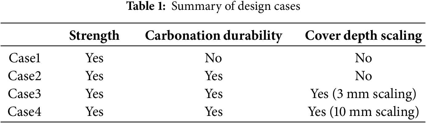
Previous researchers’ optimization designs did not consider carbonation durability, nor the impact of cover depth scaling caused by various factors. To overcome these shortcomings, as shown in the table, this study considers four design cases. Table 1 compares four design cases based on three evaluation criteria: compressive strength, carbonation durability, and cover depth scaling. Strength refers to achieving the target compressive strength; carbonation durability ensures that the carbonation depth remains smaller than the concrete cover within the service life; and cover depth scaling accounts for time-dependent loss of cover load or environmental actions. Case 1 considers only strength without carbonation or cover loss. Case 2 includes both strength and carbonation checks but assumes a constant cover with no loss. Case 3 incorporates strength and carbonation checks with a cover loss 3 mm due to a mild scaling [17]. Case 4 represents a more severe exposure condition, combining strength and carbonation checks with a higher cover loss depth 10 mm [17]. This study does not include experimental validation. The compressive strength results were obtained from the strength prediction equation, and the carbonation depth results were derived from the carbonation depth equation. Since both the strength equation and the carbonation depth equation were established based on reliable experimental data, the results presented in this paper can also be considered credible. The scaling depths of 3 and 10 mm adopted in this study were not arbitrarily chosen; they are based on actual field survey data reported by the American Concrete Institute (ACI) [17].
To describe the time-dependent surface degradation of concrete cover under long-term exposure, a bilinear scaling development model was used [30]. This model assumes a slower scaling rate during the early service life and an accelerated rate in the later period [30].
The cumulative surface scaling depth,
where:
The two rates satisfy the total cover loss constraint:
Case 3: Total Scaling Depth
Parameters derived from the constraint (
The piecewise model for Case 3 is given as:
Case 4: Total Spalling Depth
Parameters derived from the constraint (
The corresponding piecewise model is expressed as:
In summary, Case 3 represents mild deterioration (durable surface under moderate exposure), while Case 4 represents severe deterioration (weak surface or highly aggressive environment). Both cases exhibit a realistic bilinear progression—characterized by slow degradation during the first 30 years and accelerated spalling over the final 20 years.
The overall framework of this study consists of two parts: property prediction and optimization design. The property prediction part includes the strength prediction equation, the carbonation depth prediction equation, and the scaling thickness prediction equation. The objective of the optimization design is to minimize the CO2 emissions associated with the binder materials. Once the property prediction equations are established, the optimized binder composition that satisfies all the specified constraints can be obtained using the genetic algorithm toolbox in MATLAB.
The property prediction equations are described as follows. The 28-day compressive strength equation used in this study was developed through regression analysis based on a publicly available and widely adopted dataset [22]. The carbonation depth equation was validated against long-term outdoor carbonation test results [24] and is applicable to conditions involving surface cover scaling. The scaling depths of 3 and 10 mm were determined based on actual field survey data reported by the American Concrete Institute (ACI) [17]. Considering these factors, the authors conclude that the proposed slag concrete design model, which simultaneously accounts for carbonation durability and surface cover scaling, is both scientifically sound and practically reliable.
The objective function of the optimization design is described as follows. The CO2 emissions of concrete mainly originate from the binder materials, and their values may vary depending on the manufacturing processes of cement and slag.
The optimization algorithm is described as follows. In this study, the genetic algorithm toolbox in MATLAB was employed for optimization. Other researchers may select appropriate toolboxes according to their own requirements. In particular, many open-source optimization toolboxes have recently become available in Python, which can also be effectively used for similar purposes [31].
5.2.1 Case 1. Ignore Carbonation Durability
Design Case 1 is similar to existing low-carbon concrete design methods, in which carbonation durability is neglected during the optimization process. For Case 1, as shown in Table 2, the slag/binder ratio is at the upper value of 60%. This is consistent with the trend in Fig. 3b—namely, increasing the slag replacement rate reduces the CO2 emissions per unit (compressive) strength. Table 3 shows for Case 1, the design compressive strength is 30 MPa, and the as-built strength is also 30 MPa. Strength dominates the design of Case 1 because the as-built strength is the same as design compressive strength.
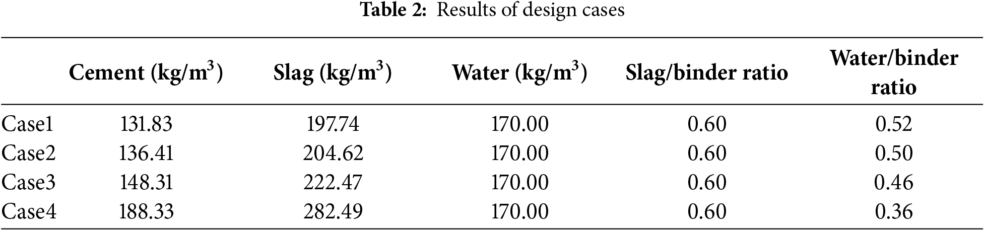
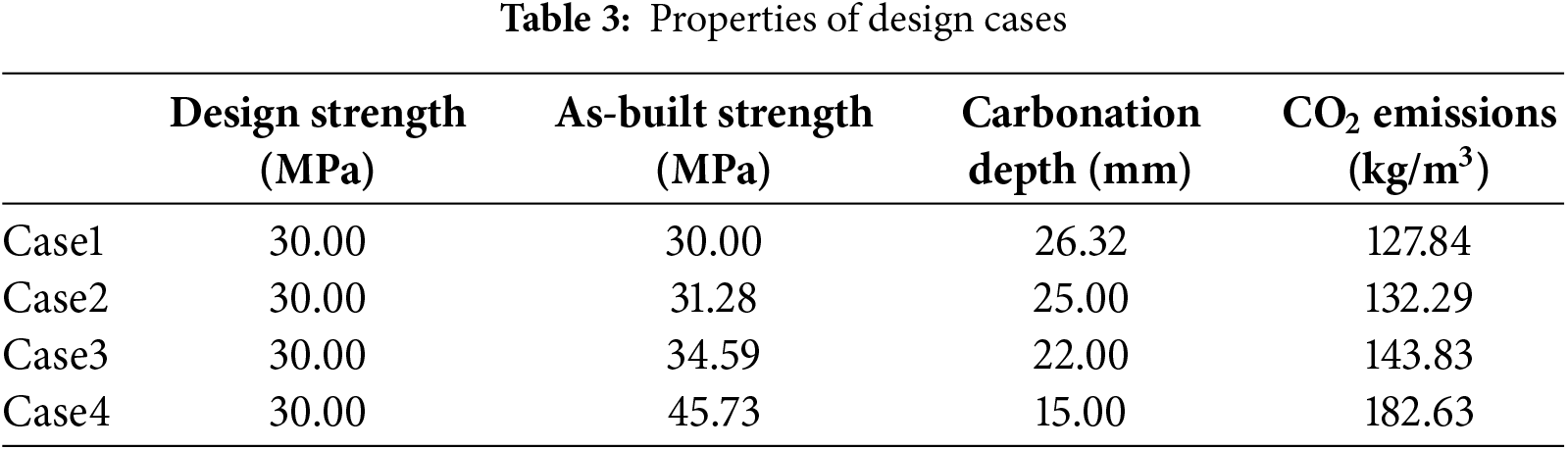
Fig. 5a illustrates the relationship between cover depth and concrete carbonation depth over a 50-year service period, assuming a constant cover depth of 25 mm. Initially, the carbonation depth is much smaller than the cover depth, ensuring that the steel reinforcement remains well protected. However, as time progresses, the carbonation front gradually deepens. At approximately 45 years, the carbonation depth reaches the cover thickness (25 mm), indicating that the carbonation front has reached the steel reinforcement. This intersection point signifies the initiation of reinforcement corrosion, marking the end of the concrete’s carbonation protection period.
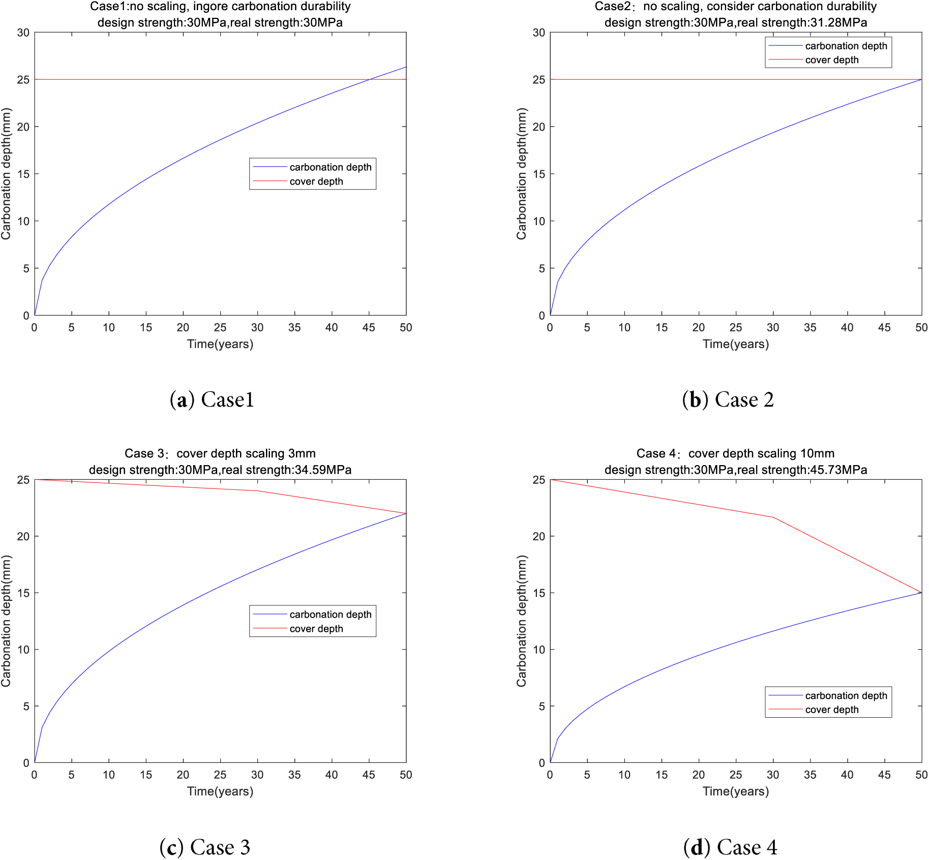
Figure 5: Carbonation depth for design cases
5.2.2 Case 2. Consider Carbonation Durability
The example in Case 1 shows that, when designing slag concrete, ignoring carbonation durability can lead to a risk of rebar corrosion [32]. To address this shortcoming, Case 2 introduces a carbonation-durability constraint in the design.
As shown in Table 3, for Case 2, the design compressive strength is 30 MPa, while the as-built strength is 31.28 MPa. It should be noted that both Case 1 and Case 2 have a design strength of 30 MPa, but the as-built strength of Case 2 is higher than that of Case 1. This is because additional binder was used in Case 2 to satisfy the carbonation durability requirement. Previous researchers have not paid attention to this issue. The concrete cover is 25 mm, and the predicted carbonation depth at the end of a 50-year service life is exactly 25 mm—that is, the carbonation front reaches the reinforcement (shown in Fig. 5b). For Case 2, carbonation durability dominates optimal design.
5.2.3 Case 3. Carbonation Durability with a Cover Depth Scaling 3 mm
Design Case 2 accounts for the effect of carbonation durability but does not consider scaling of the concrete cover during service life. Because of loads and environmental exposure, the concrete cover often scales, which reduces the concrete’s resistance to carbonation. Therefore, mixture proportioning must be used to ensure carbonation durability even when cover scaling occurs. Based on field measurements of various structures, the 50 years scaling depth vary about 3 to 10 mm [17,29,30,33,34]. 3 mm means a mild surface deterioration, corresponding to moderate exposure conditions [17]. 10 mm means a more pronounced deterioration, corresponding to more aggressive exposure environments [17].
In the design case 3, the average cover scaling depth 3 mm (effective cover reduces from about 25 to 22 mm over 50 years). The design compressive strength is 30 MPa, and the as-built strength is 34.59 MPa. Fig. 5c shows at the end of 50 years, the predicted carbonation depth equals the reduced cover thickness, i.e., the carbonation front reaches the reinforcement with a cover depth loss 3 mm (shown in Fig. 5c). For Case 3, carbonation durability dominates optimal design.
For Cases 2 and 3, Case 2 does not consider a cover scaling, whereas Case 3 assumes a cover scaling of 3 mm. Table 3 shows the as-built strengths of Cases 2 and 3 are 31.28 and 34.59 MPa, respectively. This indicates that, to meet carbonation durability requirements under time-dependent cover loss, a higher concrete compressive strength is necessary.
5.2.4 Case 4. Carbonation Durability with a Cover Depth Scaling 10 mm
In Design Case 3, the concrete cover scaling depth is assumed to be 3 mm, which is relatively low [33]. In Design Case 4, the cover depth loss is assumed to be 10 mm [33], corresponding to a more severe scaling. Table 3 shows for case 4, The design compressive strength is 30 MPa, and the as-built strength is 45.73 MPa. Fig. 5d shows the change in carbonation depth and cover depth over 50 years with a scaling depth 10 mm. Initially, the cover is much thicker than the carbonation depth, ensuring adequate protection. Over time, carbonation deepens while the cover gradually thins, and after about 50 years, the carbonation front reaches the reinforcement with a cover depth loss 10 mm. For Case 4, carbonation durability dominates optimal design.
For Design Cases 3 and 4, the cover depths loss differ—3 and 10 mm, respectively. The design results show that their as-built strengths are 34.59 and 45.73 MPa. This indicates that, as the cover scaling depth increases, a higher actual compressive strength is required to ensure the carbonation durability life of slag concrete.
5.2.5 Overall Trend of Optimal Design Results
Fig. 6a shows the relationship between water/binder mass ratio (w/b) and 28 days compressive strength. Strength decreases monotonically as w/b increases, consistent with Abrams’ law (higher w/b → higher porosity → lower compressive strength) [28].
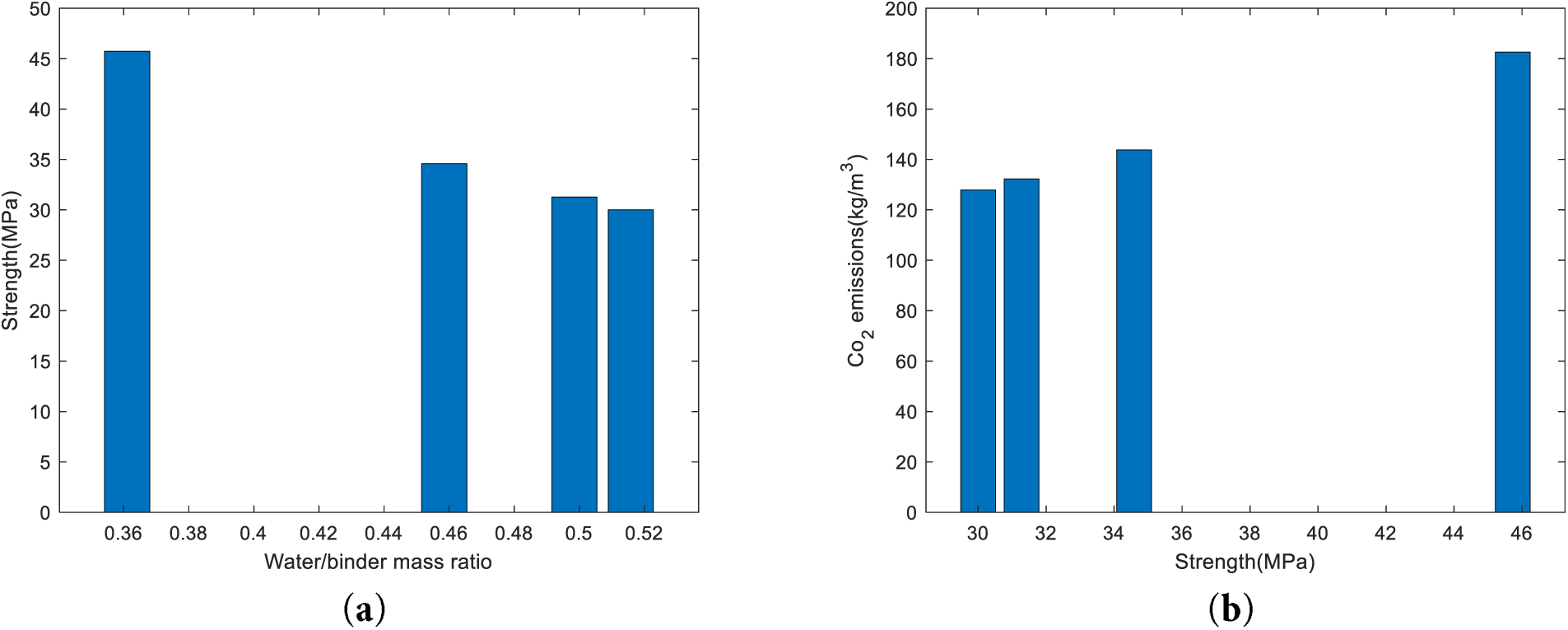
Figure 6: Overall trend of optimal design results. (a) strength vs. water/binder ratio. (b) CO2 emissions vs. strength
Fig. 6b illustrates the relationship between compressive strength and CO2 emissions of concrete mixtures. As shown, the CO2 emissions per cubic meter of concrete increase with the growth in compressive strength. Mixtures with strengths around 30–34 MPa exhibit relatively low emissions (approximately 120–150 kg/m3), whereas the mixture reaching 46 MPa shows a significantly higher emission level of about 180 kg/m3. This trend indicates that producing higher-strength concrete generally requires more cement, which contributes to increased embodied carbon.
The strength prediction equation and the carbonation depth equation indicate that as the water-to-binder ratio decreases, the compressive strength of concrete increases, and its resistance to carbonation also improves. This trend is consistent with both the optimization results of this study and general engineering practice, qualitatively demonstrating the rationality of the proposed optimization results.
The compressive strength values were obtained using a regression-based prediction model developed from a widely used open-access database [22], whereas the carbonation depth was computed using a globally recognized carbonation model that has been extensively validated in previous studies [12,23,24]. As both models were developed from well-validated experimental data, the results obtained in this study can be regarded as reliable. This provides quantitative evidence supporting the rationality of the optimization design results.
In summary, the optimization results presented in this study are both qualitatively and quantitatively reasonable, indicating that the proposed design outcomes are credible.
Previous concrete design practices generally assumed that compressive strength was the decisive performance indicator in mixture proportioning [5,6]. Several subsequent optimization studies reinforced this view by prioritizing strength as the primary target variable [8,10]. More recent machine-learning-based design frameworks have also relied heavily on strength-centered criteria, despite growing evidence that durability and environmental indicators must be considered jointly for sustainable design [35–37], similar to Case 1 in this study, which can lead to insufficient carbonation resistance. This study shows design of low-carbon concrete involves different dominant factors, namely strength-dominated and carbonation-durability-dominated approaches. To account for carbonation durability and cover scaling, Cases 2, 3, and 4 in this study demonstrate that for low-carbon slag concrete with a design strength of 30 MPa, carbonation durability governs the mix design.
The design framework proposed in this study provides a general and adaptable methodology for optimizing slag concrete mixtures with respect to strength, durability, and environmental performance. The method can be extended to various design standards and environmental conditions, offering a practical tool for developing low-carbon, high-carbonation durability concretes.
When applying this framework, the following steps are recommended: (1) define the optimization objective and use an appropriate database to estimate the CO2 emissions of slag concrete; (2) establish the compressive strength prediction equation based on the composition of slag concrete; (3) determine the carbonation depth prediction equation by considering local environmental conditions and material characteristics; and (4) apply a numerical optimization algorithm, such as a genetic algorithm [21], to obtain a mix proportion that satisfies both strength and carbonation durability requirements while minimizing CO2 emissions.
It should be noted that variations in raw materials, mix proportions, and environmental conditions across different countries and regions may cause discrepancies between local conditions and the equations presented in this paper. Therefore, the property prediction equations for compressive strength, carbonation depth, and CO2 emissions should be appropriately recalibrated to reflect local material properties, climatic conditions, and construction practices [28]. In addition, the assumption regarding workability used in this study is simplified and should be refined in future research to enhance practical applicability.
Overall, the proposed design methodology offers a universal and flexible platform for the integrated optimization of strength, carbonation durability, and carbon emissions. By applying this approach, designers can develop slag concrete mixtures that effectively reduce carbon emissions while improving carbonation resistance, thereby contributing to the sustainable development of the concrete industry. In addition, the design strength of the design case in this study is 30 MPa. If high-strength concrete is being designed, for example, with a design strength greater than 45.73 MPa in design case 4, the mix design will be dominated by compressive strength, not carbonation durability.
Earlier approaches for designing low-carbon concrete did not account for carbonation durability or the progressive loss of cover due to surface scaling, both of which may lead to an increased risk of reinforcement corrosion. To overcome these limitations, this study proposes an improved design framework for low-carbon slag concrete that simultaneously considers carbonation durability and cover scaling effects within the mix proportioning process. The main conclusions are as follows:
(1) Based on the experimental data, a linear predictive model was developed to estimate the 28-day compressive strength of slag concrete, achieving a correlation coefficient of R = 0.87711 and a root mean square error (RMSE) of 7.55 MPa. The main advantage of mechanism-based strength equations lies in their strong physical interpretability—each parameter corresponds to a clear physical process, satisfying the requirements of design codes for physical significance.
(2) By integrating the strength and carbon-emission models, the carbon-emission efficiency was assessed. Across all water–binder ratios (0.3, 0.4, 0.5), the CO2 emissions per unit strength (kg/m3·MPa) decrease steadily with increasing slag content. The small differences among the three w/b ratios indicate that carbon efficiency is mainly governed by slag replacement rather than the w/b ratio.
(3) Case 1 (without carbonation consideration): When the actual compressive strength equals the design target of 30 MPa, the predicted carbonation depth after 50 years exceeds the 25 mm cover thickness, resulting in potential corrosion. Strength alone governs the mix design.
(4) Case 2 (with carbonation consideration): When carbonation durability is included, the required actual strength increases to 31.28 MPa, ensuring that the carbonation depth after 50 years equals the 25 mm cover thickness. In this case, carbonation resistance governs the design.
(5) Case 3 (carbonation + mild scaling, 3 mm): Considering a cover loss of 3 mm due to scaling, the actual strength requirement rises to 34.59 MPa to maintain corrosion resistance. Here, carbonation durability remains the controlling factor, while surface scaling necessitates a moderate increase in strength.
(6) Case 4 (carbonation + severe scaling, 10 mm): Under harsher conditions with 10 mm cover loss, the required strength further increases to 45.73 MPa to ensure that the carbonation depth equals the reduced effective cover. As in Case 3, carbonation resistance dominates the mix design, but intensified scaling demands higher strength.
(7) Overall trends: As compressive strength increases, the water-to-binder ratio decreases, leading to higher binder-related CO2 emissions. The optimization results are consistent with practical engineering trends, indicating that balancing mechanical performance, durability, and environmental impact is essential for achieving sustainable low-carbon concrete design.
Acknowledgement: None.
Funding Statement: This research was supported by the National Natural Science Foundation of China (No. 52463034). This research was supported by the Korea Institute of Energy Technology Evaluation and Planning funded by the Ministry of Trade, Industry and Energy (No. 2025-02314098) of the Republic of Korea. This research was supported by the Regional Innovation System & Education (RISE) program through the Gangwon RISE Center, funded by the Ministry of Education (MOE) and the Gangwon State (G.S.), Republic of Korea (2025-RISE-10-002).
Author Contributions: Kang-Jia Wang: Investigation, Data curation, Writing—original draft. Hongzhi Zhang: Data curation, Investigation. Runsheng Lin: Data curation, Investigation. Jiabin Li: Data curation, Investigation. Xiao-Yong: Writing—review & editing, Funding acquisition, Formal analysis. All authors reviewed the results and approved the final version of the manuscript.
Availability of Data and Materials: The data presented in this study are available from the corresponding authors upon reasonable request.
Ethics Approval: Not applicable.
Conflicts of Interest: The authors declare no conflicts of interest to report regarding the present study.
References
1. Lim SG, Tay YWD, Paul SC, Lee J, Amr IT, Fadhel BA, et al. Carbon capture and sequestration with in situ CO2 and steam integrated 3D concrete printing. Carbon Capture Sci Technol. 2024;13:100306. doi:10.1016/j.ccst.2024.100306. [Google Scholar] [CrossRef]
2. Tay YWD, Lim SG, Fadhel BA, Amr IT, Bamagain RA, Al-Hunaidy AS, et al. Potential of carbon dioxide spraying on the properties of 3D concrete printed structures. Carbon Capture Sci Technol. 2024;13:100256. doi:10.1016/j.ccst.2024.100256. [Google Scholar] [CrossRef]
3. Wang XY. Evaluation of the properties of cement-calcined Hwangtoh clay-limestone ternary blends using a kinetic hydration model. Constr Build Mater. 2021;303:124596. doi:10.1016/j.conbuildmat.2021.124596. [Google Scholar] [CrossRef]
4. Patel R, Babaei-Ghazvini A, Dunlop MJ, Acharya B. Biomaterials-based concrete composites: a review on biochar, cellulose and lignin. Carbon Capture Sci Technol. 2024;12:100232. doi:10.1016/j.ccst.2024.100232. [Google Scholar] [CrossRef]
5. DeRousseau MA, Kasprzyk JR, Srubar WV. Computational design optimization of concrete mixtures: a review. Cem Concr Res. 2018;109:42–53. doi:10.1016/j.cemconres.2018.04.007. [Google Scholar] [CrossRef]
6. Mahjoubi S, Barhemat R, Guo P, Meng W, Bao Y. Prediction and multi-objective optimization of mechanical, economical, and environmental properties for strain-hardening cementitious composites (SHCC) based on automated machine learning and metaheuristic algorithms. J Clean Prod. 2021;329:129665. doi:10.1016/j.jclepro.2021.129665. [Google Scholar] [CrossRef]
7. Shobeiri V, Bennett B, Xie T, Visintin P. Mix design optimization of concrete containing fly ash and slag for global warming potential and cost reduction. Case Stud Constr Mater. 2023;18:e01832. doi:10.1016/j.cscm.2023.e01832. [Google Scholar] [CrossRef]
8. Fan M, Li Y, Shen J, Jin K, Shi J. Multi-objective optimization design of recycled aggregate concrete mixture proportions based on machine learning and NSGA-II algorithm. Adv Eng Softw. 2024;192:103631. doi:10.1016/j.advengsoft.2024.103631. [Google Scholar] [CrossRef]
9. Zhang J, Huang Y, Wang Y, Ma G. Multi-objective optimization of concrete mixture proportions using machine learning and metaheuristic algorithms. Constr Build Mater. 2020;253:119208. doi:10.1016/j.conbuildmat.2020.119208. [Google Scholar] [CrossRef]
10. Zheng W, Shui Z, Xu Z, Gao X, Zhang S. Multi-objective optimization of concrete mix design based on machine learning. J Build Eng. 2023;76:107396. doi:10.1016/j.jobe.2023.107396. [Google Scholar] [CrossRef]
11. Peng L, Miao X, Zhu JX, Zhang MQ, Zheng XQ, Li HY, et al. Hybrid machine learning and multi-objective optimization for intelligent design of green and low-carbon concrete. Sustain Mater Technol. 2025;45:e01605. doi:10.1016/j.susmat.2025.e01605. [Google Scholar] [CrossRef]
12. Papadakis VG, Tsimas S. Supplementary cementing materials in concrete: part I efficiency and design. Cem Concr Res. 2002;32(10):1525–32. doi:10.1016/S0008-8846(02)00827-X. [Google Scholar] [CrossRef]
13. Ekolu SO. Model for practical prediction of natural carbonation in reinforced concrete: part 1—formulation. Cem Concr Compos. 2018;86:40–56. doi:10.1016/j.cemconcomp.2017.10.006. [Google Scholar] [CrossRef]
14. Zhang J, Zhang X, Li X, Song Z, Shao J, Zhang S, et al. Prediction of CO2 adsorption of biochar under KOH activation via machine learning. Carbon Capture Sci Technol. 2024;13:100309. doi:10.1016/j.ccst.2024.100309. [Google Scholar] [CrossRef]
15. GB/T 50476-2019. Standard for design of concrete structure durability. Beijing, China: China Architecture Publishing & Media Co., Ltd.; 2019. [Google Scholar]
16. MathWorks. [cited 2025 Sep 1]. Available from: https://www.mathworks.com/discovery/genetic-algorithm.html. [Google Scholar]
17. NRMCA. CIP 2—scaling concrete surfaces; 1998 [cited 2025 Sep 1]. Available from: https://www.nrmca.org/wp-content/uploads/2021/01/02pr.pdf. [Google Scholar]
18. KEITI. [cited 2025 Sep 1]. Available from: https://www.keiti.re.kr/site/keiti/02/10202100000002023101610.jsp. [Google Scholar]
19. CEB-FIP. FIB model code for concrete structures. Lausanne, Switzerland: International Federation for Structural Concrete; 2020. [Google Scholar]
20. Choi JH, Kim D, Ko MS, Lee DE, Wi K, Lee HS. Compressive strength prediction of ternary-blended concrete using deep neural network with tuned hyperparameters. J Build Eng. 2023;75:107004. doi:10.1016/j.jobe.2023.107004. [Google Scholar] [CrossRef]
21. Yeh IC. Computer-aided design for optimum concrete mixtures. Cem Concr Compos. 2007;29(3):193–202. doi:10.1016/j.cemconcomp.2006.11.001. [Google Scholar] [CrossRef]
22. Yeh IC. Concrete compressive strength; 2007 [cited 2025 Sep 1]. Available from: https://archive.ics.uci.edu/dataset/165/concrete+compressive+strength. [Google Scholar]
23. Demis S, Papadakis VG. A software-assisted comparative assessment of the effect of cement type on concrete carbonation and chloride ingress. Comput Concr. 2012;10(4):391–407. doi:10.12989/cac.2012.10.4.391. [Google Scholar] [CrossRef]
24. Demis S, Efstathiou MP, Papadakis VG. Computer-aided modeling of concrete service life. Cem Concr Compos. 2014;47:9–18. doi:10.1016/j.cemconcomp.2013.11.004. [Google Scholar] [CrossRef]
25. Oh BH, Jang SY. Prediction of diffusivity of concrete based on simple analytic equations. Cem Concr Res. 2004;34(3):463–80. doi:10.1016/j.cemconres.2003.08.026. [Google Scholar] [CrossRef]
26. Song HW, Kwon SJ, Byun KJ, Park CK. Predicting carbonation in early-aged cracked concrete. Cem Concr Res. 2006;36(5):979–89. doi:10.1016/j.cemconres.2005.12.019. [Google Scholar] [CrossRef]
27. Papadakis VG, Vayenas CG, Fardis MN. Experimental investigation and mathematical modeling of the concrete carbonation problem. Chem Eng Sci. 1991;46(5–6):1333–8. doi:10.1016/0009-2509(91)85060-B. [Google Scholar] [CrossRef]
28. Wang XY, Lee HS. Modeling the hydration of concrete incorporating fly ash or slag. Cem Concr Res. 2010;40(7):984–96. doi:10.1016/j.cemconres.2010.03.001. [Google Scholar] [CrossRef]
29. Sarja A, Vesikari E. Durability design of concrete structures. London. UK: E & FN Spon; 2005. [Google Scholar]
30. Jiang WQ, Liu QF. Chloride transport in concrete subjected to freeze-thaw cycles-a short review. J Chin Ceram Soc. 2020;48:258–72. [Google Scholar]
31. SciPy. Fundamental algorithms for scientific computing in Python; 2025 [cited 2025 Oct 17]. Available from: https://scipy.org/. [Google Scholar]
32. Wang XY. CO2 uptake of slag-blended concrete. Environ Sci Pollut Res. 2021;28(35):48890–904. doi:10.1007/s11356-021-14184-y. [Google Scholar] [PubMed] [CrossRef]
33. Zhu F, Zhao T, Wang Z, Wang P. Modification and application of chloride diffusion model based on frost damage and surface scaling. J Build Mater. 2015;18(6):1065–9. [Google Scholar]
34. JTG D40-2011. Consultants, specifications for design of highway cement concrete pavement. Beijing, China: China Communications Press; 2011. [Google Scholar]
35. Sun J, Zhang J, Gu Y, Huang Y, Sun Y, Ma G. Prediction of permeability and unconfined compressive strength of pervious concrete using evolved support vector regression. Constr Build Mater. 2019;207(1):440–9. doi:10.1016/j.conbuildmat.2019.02.117. [Google Scholar] [CrossRef]
36. Campos HF, Klein NS, Marques Filho J. Proposed mix design method for sustainable high-strength concrete using particle packing optimization. J Clean Prod. 2020;265:121907. doi:10.1016/j.jclepro.2020.121907. [Google Scholar] [CrossRef]
37. Biswal US, Dinakar P. A mix design procedure for fly ash and ground granulated blast furnace slag based treated recycled aggregate concrete. Clean Eng Technol. 2021;5:100314. doi:10.1016/j.clet.2021.100314. [Google Scholar] [CrossRef]
Cite This Article
 Copyright © 2026 The Author(s). Published by Tech Science Press.
This work is licensed under a Creative Commons Attribution 4.0 International License , which permits unrestricted use, distribution, and reproduction in any medium, provided the original work is properly cited.
 Downloads
 Citation Tools