
 Submit a Paper
 Propose a Special lssue
 Open Access
ARTICLE

A novel Angle-Constrained Optimization method of Conformal Lattice Structures
1 State Key Laboratory of Structural Analysis for Industrial Equipment, Department of Engineering Mechanics, International Research Center for Computational Mechanics, Dalian University of Technology, Dalian, China
2 Ningbo Research Institute of Dalian University of Technology, Ningbo, China
3 Shenyang Aircraft Design and Research Institute, Aviation Industry Corporation of China (AVIC), Shenyang, China
4 School of Chemical Machinery and Safety, Dalian University of Technology, Dalian, China
* Corresponding Author: Kun Yan. Email:
(This article belongs to the Special Issue: Scientific Computing and Its Application to Engineering Problems)
Computer Modeling in Engineering & Sciences 2026, 146(2), 8 https://doi.org/10.32604/cmes.2026.076948
Received 29 November 2025; Accepted 27 January 2026; Issue published 26 February 2026
 View Full Text
 Download PDF
Abstract
Conformal truss-like lattice structures face significant manufacturability challenges in additive manufacturing due to overhang angle limitations. To address this problem, we propose a novel angle-constrained optimization method grounded in the global adjustment of nodal coordinates. First, a build direction is selected to minimize the number of violating struts. Then, an angular-constraint matrix is assembled from strut direction vectors, and analytical sensitivities with respect to nodal coordinates are derived to enable efficient constrained optimization under nonlinear angular inequality constraints. Numerical studies on two complex curved-surface lattices demonstrate that all overhang violations are eliminated while only minor changes are induced in global stiffness and strength. In particular, the maximum displacement of an ergonomic insole varies by only 2.87% after optimization. The results confirm the method’s versatility and engineering robustness, providing a practical approach for additive manufacturing-oriented lattice structure design.Keywords
Due to high specific strength and multifunctional characteristics [1–4], lattice structures have been widely applied in aerospace, biomedical engineering, and other fields to achieve lightweight design and functional integration [5,6]. With the rapid advancement of additive manufacturing (AM) technologies [7–10], lattice design has evolved from traditional regular unit patterns to conformal configurations capable of adapting to complex boundaries, thereby driving the paradigm shift from “geometry-driven” to “performance-driven” design. However, this increase in design freedom has also introduced new manufacturing challenges, among which the overhang angle limitations significantly affect print quality and manufacturability [11–14]. In conformal lattice structures, large overhang regions are often formed, which significantly increases the risk of defects and undermines manufacturing stability.
To address the challenges posed by overhang angle constraints, existing research generally follows two main strategies. The first strategy is the introduction of support structures to facilitate printing [15–18]. While this approach has proven effective for large-scale solid components [19], it faces substantial difficulties in lattice structures, where internal supports are often difficult to completely remove during post-processing, frequently leading to residual material issues [20]. The second strategy incorporates manufacturing constraints directly into the initial design stage, enabling the optimization of self-supporting structures to minimize or completely avoid unmanufacturable geometries [21–23]. This approach simultaneously balances manufacturability and functional performance during structural generation and has emerged as an important trend in manufacturability-oriented optimization [24,25].
For self-supporting design, most existing methods incorporate overhang-angle or self-supporting criteria into continuum topology-optimization frameworks, such as SIMP [26–28], level-set [29,30], BESO [31,32] and feature-driven approaches [33,34] that regulate material distribution or boundary evolution to satisfy manufacturability requirements.
Despite these advances in continuous structure optimization, explicit parametric lattice models with strut-wise overhang angle control remain relatively limited. In particular, there is still a lack of algorithms that directly adjust the nodal coordinates of conformal lattices to enforce overhang-angle constraints while preserving boundary conformity and internal connectivity. This difficulty becomes more evident when adapting to complex curved-surface boundaries or integrating multiple functional regions, where existing approaches often struggle to simultaneously ensure geometric manufacturability and structural integrity [35,36]. Moreover, studies on biomimetic lattices reveal the inherent conflict between boundary adaptability and manufacturability in lattice design [37,38]. Similar observations have been reported for functionally graded lattices, where spatially varying architectures increase the difficulty of satisfying manufacturability constraints [39–42]. This trade-off has also been noted in related lattice-design/generation and additive-manufacturing studies [43–47]. In high-complexity engineering applications, such as the lightweight optimization of aerospace components, how to satisfy manufacturing constraints while maintaining structural rationality has become a pressing issue [25,48]. Unlike traditional support-based printing strategies [17,49], which rely on auxiliary supports that are particularly challenging to remove within dense lattice interiors, and continuum/surface-level self-supporting topology optimization [50–52], which primarily regulates boundary inclination or material distribution rather than addressing the overhang angles of each strut in an explicit lattice, the present study targets explicit parametric conformal truss-like lattices and enforces manufacturability at the strut level. Here, “truss-like” refers to the geometric/topological connectivity of struts, whereas the mechanical response is discretized using beam elements in this work. This approach directly adjusts the nodal coordinates, enabling a more precise and automated solution to ensure compliance with overhang angle constraints. In this way, it addresses the longstanding limitations in existing methods that struggle to balance manufacturability with structural integrity, offering a highly adaptable and robust solution for complex, real-world lattice designs.
This paper proposes an angle-constrained optimization method for conformal lattice structures in additive manufacturing, aiming to satisfy overhang-angle manufacturability requirements while preserving the geometric fidelity and functional integrity of the original design. First, the build direction is selected (or screened) to reduce the initial number of over-limit struts, thereby providing a favorable starting point for subsequent optimization. Second, the angles between all struts and the build direction are computed and aggregated to construct an angular-constraint matrix. Based on this, the coordinate changes of moveable nodes are taken as design variables, and analytical sensitivity expressions are derived to provide gradient information for efficient solution. Third, a nonlinear inequality-constrained optimization model is formulated and solved to minimize the global nodal perturbation while strictly enforcing the allowable overhang-angle intervals, thereby achieving a coordinated balance between manufacturability and geometric fidelity. Finally, the method is verified by re-checking overhang-angle compliance and comparing the numerical responses between the baseline design and the optimized design in the examples.
The remainder of this paper is organized as follows: Section 2 introduces the overhang-angle manufacturability issue in conformal lattices. Section 3 presents the proposed angle-constrained optimization method and its solution procedure. Section 4 provides numerical examples to validate the method. Section 5 concludes the paper and outlines future work.
Conformal lattice-filled structures (Fig. 1) can precisely match complex infill domain [35,53–55]. However, this adaptability introduces directional dependence; local strut orientations vary with the external geometry, increasing the chance that certain struts form angles with the build direction below the critical overhang threshold. Existing strategies for improving manufacturing adaptability fall into two main categories. The first strategy is to introduce support structures to support manufacturing; however, these methods are often constrained by the limited internal space within lattice structures. The second is manual or semi-automated adjustment of nodal coordinates to satisfy angle constraints. However, such adjustments typically depend on heuristic experience and scales poorly for large lattice designs.
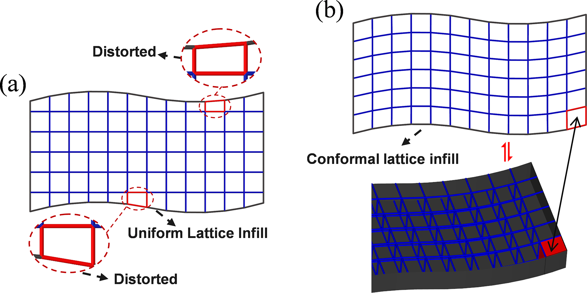
Figure 1: Comparison of uniform lattice infill (a) and conformal lattice infill (b), illustrating the improved boundary conformity of conformal configurations.
To address this challenge, we propose an angle-constrained optimization method based on finite element nodal coordinate adjustment, specifically targeting over-limit overhang angles in conformal lattice structures, as shown in Fig. 2.
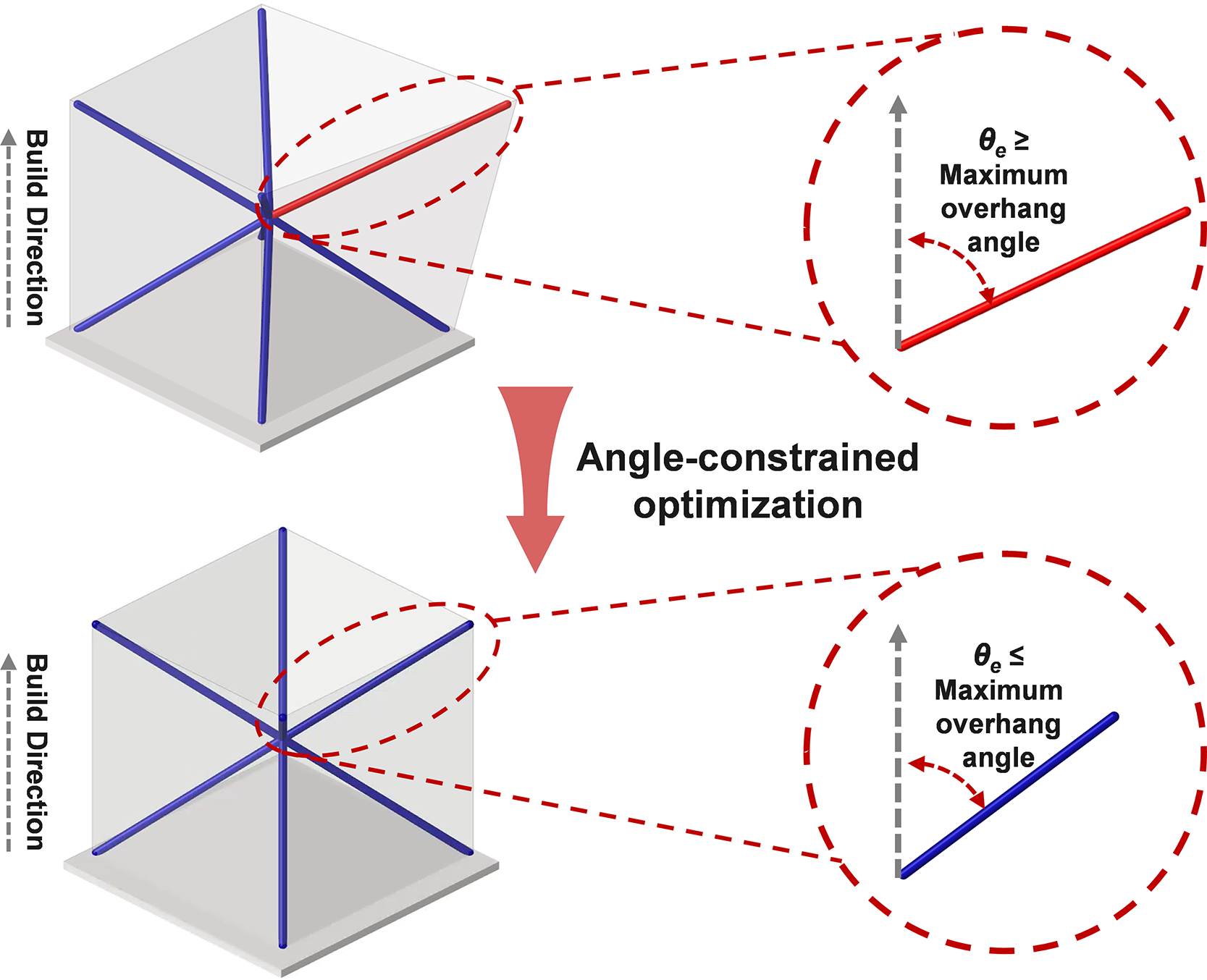
Figure 2: Schematic of overhang-angle-constrained optimization for lattice structures in additive manufacturing (red struts: over-limit struts; blue struts: non-over-limit struts).
3 Angle-Constrained Optimization Algorithm for Additive Manufacturing
3.1 Construction of the Angular Constraint Matrix
We propose an angular-constraint matrix construction method for the efficient identification of manufacturing angle violations. The method constructs an angular-constraint matrix based on the strut direction vectors and takes as input the three-dimensional coordinates of all end nodes of struts in the target lattice structure. First, the angle between each strut direction vector and the build direction vector is computed. Next, over-limit struts are automatically identified according to the allowable manufacturing range. Then, all individual strut angle constraints are reformulated into a standardized inequality form and embedded as a system of angular constraints into the optimization solver. Finally, the optimization process aims to minimize the total nodal perturbation by iteratively updating only the pre-selected moveable nodes, while keeping the fixed boundary nodes unchanged; the specific selection strategies for moveable and fixed nodes are detailed in Section 3.1.1 and illustrated in Fig. 3. The detailed workflow proceeds as follows.

Figure 3: Optimization strategies with and without geometric conformity constraints: (a) With geometric conformity constraints, boundary nodes are fixed to and aligned with the prescribed skin surface, leaving only internal nodes as design variables; (b) Without geometric conformity constraints, all nodes (including boundary and internal nodes) are treated as design variables, allowing the lattice geometry to evolve freely.
3.1.1 Identification of Moveable Nodes
In the angular constraint optimization process, an initial screening of structural nodes is required to determine the set of moveable nodes for optimization. This step not only defines the dimensionality of the optimization variable space but also directly affects the convergence efficiency and feasibility of satisfying the geometric constraints. Depending on whether the lattice must maintain geometric continuity or embedding constraints with external structures (e.g., skins), two node-selection strategies are introduced. In both strategies, interior nodes are always included in the set of moveable nodes. The difference lies in whether the surface (boundary) nodes are fixed to preserve geometric conformity or are also allowed to move together with the interior nodes.
(a) Optimization strategy with geometric conformity constraints. When a lattice structure requires geometric continuity or structural embedding with an external skin, surface (boundary) nodes must be strictly aligned with the prescribed external geometry. To achieve this, a geometric feature recognition algorithm is employed to extract all outer boundary surface nodes, which are designated as fixed nodes with unchanged coordinates during optimization. Their perturbations are set to zero and explicitly excluded from moveable nodes via a mask matrix (Fig. 3). This strategy significantly reduces the optimization variable space and improves computational efficiency; however, it also increases coupling between angular constraints, imposing higher demands on the global coordination capability of the optimization algorithm.
(b) Optimization strategy without geometric conformity constraints. For internal lattice infill structures without external boundary conformity requirements, all nodes can be treated as optimization variable space (Fig. 3). This strategy provides greater design freedom and an expanded feasible space, enabling more complex geometric adjustments and angle coordination. While computational cost increases correspondingly, the lack of geometric continuity constraints broadens the feasible region, thereby improving the final global compliance rate of strut angles.
These two configurations are explicitly illustrated in Fig. 3: in strategy (a) boundary nodes are fixed and only interior nodes are treated as moveable (effective) nodes, whereas in strategy (b) both interior and boundary nodes are included in the design-variable set because no external conformity constraint is imposed.
3.1.2 Angular Constraint Matrix Construction
To ensure that each strut in the structure complies with angular constraints relative to the additive manufacturing (AM) build direction, it is first necessary to establish the formulation for the strut direction vector and the corresponding angle calculation (Fig. 4). This formulation serves as the basis for embedding angular constraints into the optimization formulation. For an arbitrary e-th strut, its first and second end nodes are
where (xi, yi, zi) and (xj, yj, zj) are the coordinates of i-th node and j-th node, respectively.
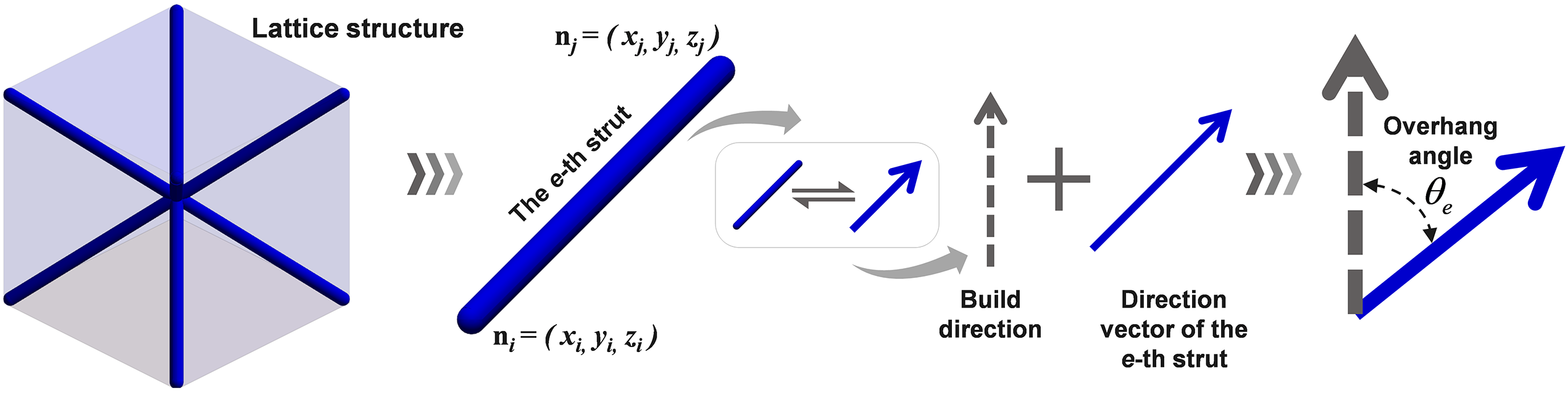
Figure 4: Schematic of the workflow for calculating the overhang angle between the e-th strut direction vector and the build direction.
Then, the unit direction vector
where
The cosine value of the overhang angle
where
Then, the cosine values of the overhang angles
where Ne is the total number of struts.
Building on
The feasible overhang-angle domain of the e-th strut is defined as:
For numerical implementation, the union constraint in Eq. (5) can be enforced using the following equivalent continuous inequality:
3.2 Optimization Formulation and Numerical Implementation
3.2.1 Optimization Formulation
To ensure all strut overhang angles in the lattice structure remain within the allowable manufacturing range during the additive manufacturing (AM) process, the strut orientation adjustment problem is reformulated as a multivariable optimization problem with nonlinear inequality constraints. The objective is to minimize the total nodal perturbation subject to angular constraints, thereby preserving the geometric fidelity and functional integrity of the original structure.
In this paper, the optimization formulation is expressed as:
where f is the objective function, Nm is the number of moveable (effective) nodes and
The detailed components of the optimization model are described as follows:
Objective Function. To quantify the geometric perturbation during optimization, the objective is to minimize the sum of squared movement magnitudes of all effective nodes, as given in Eq. (9a).
Design Variables. The design variable
In this study, boundary nodes (e.g., those located on conformal surfaces) are excluded from the moveable nodes via a masking strategy, with their displacements fixed to zero to ensure that geometric continuity or embedding conditions are preserved throughout the optimization process.
Constraints. To ensure the manufacturability of the target structure, the orientation of each strut is required to satisfy an overhang-angle constraint with respect to the build direction. Specifically,
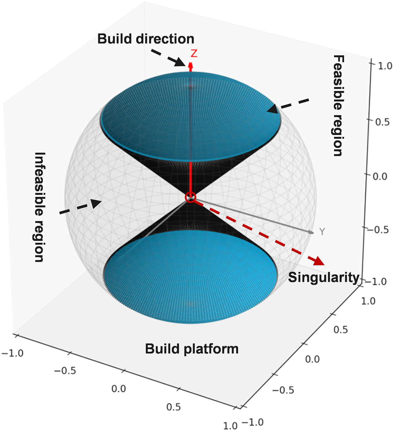
Figure 5: Distribution characteristics of struts under manufacturing angular constraints.
Moreover, Fig. 5 highlights a critical phenomenon—a singularity near 90°. When the angle between a strut and the build direction approaches 90°, its contribution to the sensitivity analysis tends to become very small, which may cause stalling in the iterative optimization process and even lead to local optima or convergence failure. A similar issue has also been reported in continuum-level self-supporting optimization [56,57]. Unlike continuum/surface-level approaches that avoid this singularity by reformulating the overhang measure, we keep the strut–build angle definition for lattice graphs and stabilize the optimization near 90° using a lightweight perturbation strategy, which is simple to implement and computationally efficient.
Constraint on nodal movement (control of geometric variation). To prevent excessive local geometric distortion during optimization, the coordinate-change increment of each moveable node is bounded by a prescribed upper limit, as imposed in Eq. (9c), where
3.2.2 Numerical Solution and Implementation
The optimization model formulated in this study is a nonlinear minimization problem subject to inequality constraints and variable bounds. For numerical implementation, constrained optimizers from the Python SciPy library are employed, including the trust-region method [58] (trust-constr) and sequential least squares programming [59] (SLSQP). The trust-region method offers strong numerical stability when solving large-scale, sparse problems with relatively smooth gradients, while SLSQP provides favorable convergence behavior for problems of moderate dimensionality with more complex constraints. In general, both algorithms are capable of handling nonlinear constraints and achieving a balance between computational efficiency and accuracy. The specific choice of solver can therefore be flexibly determined based on the problem size, gradient characteristics, and constraint complexity, so as to trade off between computational cost and solution quality. To improve optimization efficiency and enhance the relevance of the search direction, an angle sensitivity factor is introduced in this study to quantify the influence of each strut’s inclination on the objective function. The sensitivity factor is defined as follows:
where
To verify the effectiveness of the proposed method, the optimization performance is quantitatively assessed from two perspectives: the strut angle violation ratio and the magnitude of geometric modification. These evaluations confirm the method’s effectiveness in terms of manufacturing adaptability and the preservation of geometric integrity. The strut angle violation ratio
where
3.3 Workflow of the Angle-Constrained Optimization Algorithm
Based on the above formulation, the overall workflow of the angle-constrained optimization algorithm is summarized in Fig. 6, and the specific steps are as follows:
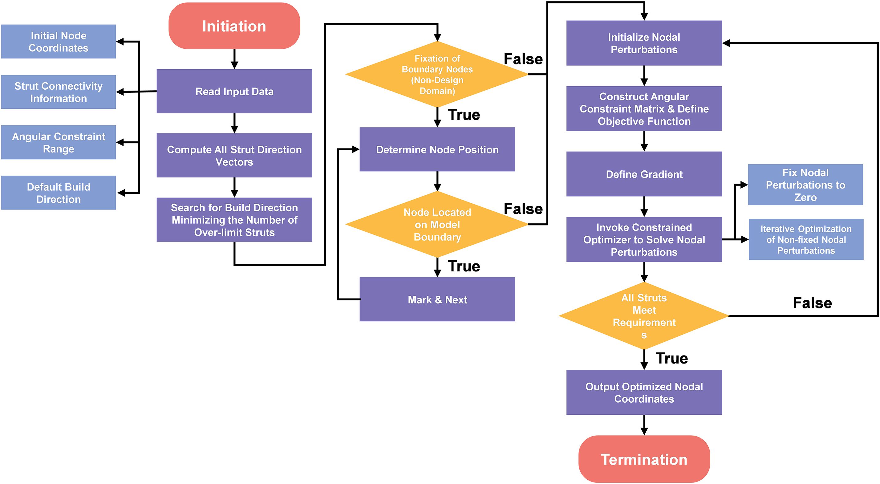
Figure 6: Workflow of the overhang angle optimization algorithm for lattice structures.
Step 1—Parameter Input, input the initial node coordinates, strut connectivity, printing direction vector, and allowable overhang angle range, providing fundamental data for subsequent modeling.
Step 2—Initialization, read the structural information of the model, parse the upper and lower bounds of the angle constraints, and set the default build direction.
Step 3—Strut Orientation Calculation, compute the unit direction vector of each strut and evaluate its angle with respect to the build direction via the dot product. If the angle falls outside the specified range, mark the strut as an “over-limit strut” and add it to the angle constraint set.
Step 4—Pre-Optimization of Build Direction, within the allowable perturbation range of the build direction, search for an initial direction that minimizes the number of over-limit struts to improve the initial feasibility.
Step 5—Moveable Node Identification, a geometric feature–based identification algorithm is used to extract all nodes on the external boundary surfaces, which are then designated as fixed nodes whose coordinates remain unchanged throughout the optimization. The remaining non-boundary nodes are classified as moveable nodes and taken as design variables for optimization.
Step 6—Optimization Formulation, construct a nonlinear angle-constrained node displacement minimization model. Introduce a sensitivity-guided mechanism to identify key nodes with significant influence on angles, thus improving the convergence of the optimization path.
Step 7—Numerical Solution, invoke a constrained optimizer (e.g., trust-region method trust-constr or SLSQP) to iteratively solve for the design variables, dynamically adjusting node positions to eliminate over-limit strut(s). After each iteration, recompute the angles and check constraint satisfaction.
Step 8—Convergence Check, if all strut angles satisfy the manufacturing constraints, terminate the iteration; otherwise, return to Step 6 and continue optimization until the termination criterion is met or the maximum number of iterations is reached.
Step 9—Result Output, optimized node coordinate list and angle pass rate for all struts.
4.1 Conformal Lattice Modeling and Numerical Validation
4.1.1 Introduction to the Conformal Lattice Modeling Method
The angle-constrained optimization method proposed in this study is primarily applied to the strut nodes of conformal lattice structures, making the accurate acquisition of lattice structure parameters crucial. This section provides a brief overview of the conformal lattice modeling method and details the process of obtaining the strut nodes of the conformal lattice structure.
Specifically, the initial conformal lattice data are generated using a mesh-driven parameterization workflow (Fig. 7). In the generation of lattice infill structures, the target infill domain is first determined, and then it is discretized into a hexahedral finite element mesh, which serves as the geometric carrier. Next, through a mapping-based procedure, the predefined conformal lattice unit cell template is embedded into each hexahedral element, thus obtaining the nodal coordinates and strut connectivity information. These data are then globally assembled to form the complete lattice structure.
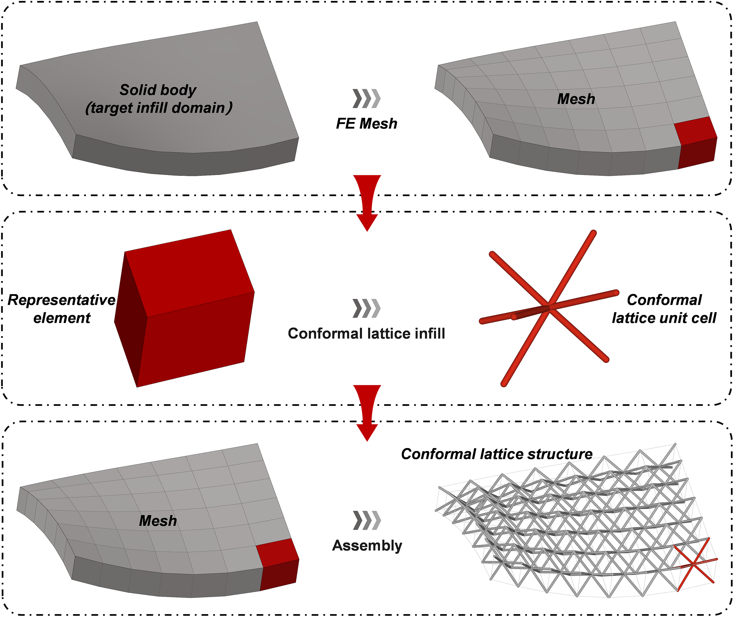
Figure 7: Conformal lattice modeling workflow.
Based on the complete lattice structure, the strut nodes required for the angle-constrained optimization method proposed in this study are then extracted. In practice, we use Gmsh to generate the hexahedral mesh for mesh discretization and the determination of the target infill domain, while the remaining processes are completed using a self-developed conformal lattice infill tool, which is based on the aforementioned mesh-driven parameterization workflow.
4.1.2 Numerical Model Validation
The validation of the numerical model is a crucial step in evaluating the effectiveness of the angle-constrained optimization method proposed in this study. This section will provide a detailed description of the numerical validation approach used to ensure the reliability and accuracy of the optimization process.
In the angle-constrained adjustment of the conformal lattice structure, the proposed method recalculates the angles of each strut using the updated nodal coordinates and compares them with the allowable intervals specified in the global angular constraint matrix. Each strut’s angle must satisfy the preset overhang angle constraints. When all struts’ angles comply with these constraints, the optimization process terminates and is considered successful; otherwise, if any strut violates the constraints, the algorithm is deemed to have failed. This process ensures the manufacturability of the structure at the numerical level and provides a direct evaluation of the algorithm’s effectiveness.
Through this validation process, we confirm the applicability and effectiveness of the proposed optimization method in additive manufacturing and provide theoretical support for its further practical application.
4.2 Case 1: An Aeroengine Turbine Blade
To validate the applicability of the proposed angle-constrained optimization method under complex boundary conditions and strong geometric curvature fields, this study employs a specific model of turbine blade from an aeroengine as the validation case, as shown in Fig. 8. The blade structure exhibits key features including high curvature at the leading edge, smoothly varying curvature on the pressure and suction surfaces, and a thin-walled transition at the trailing edge, thereby reflecting the application challenges of conformal lattice infill design in highly complex engineering configurations.
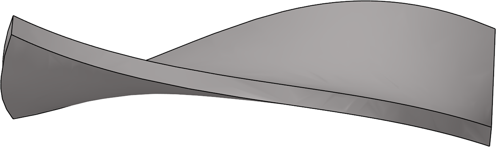
Figure 8: Geometric model of the aeroengine turbine blade.
The lattice structure is constructed using a self-developed parametric design platform [60], utilizing a Body-Centered Cubic (BCC) unit cell as the basic structural element. A three-dimensional conformal arrangement is achieved via an isoparametric mapping algorithm, with 19 unit cells arranged along the transverse direction, 9 and 5 layers arranged sequentially along the longitudinal axis, and 1 layer along the height direction. In total, 126 periodic unit cells are generated, with a total of 1008 struts. This configuration creates a three-dimensional conformal lattice infill structure that matches the blade’s curved surface profile (as shown in Fig. 9). Additionally, a uniform allowable overhang-angle domain is applied to all struts, where the two threshold angles are set to
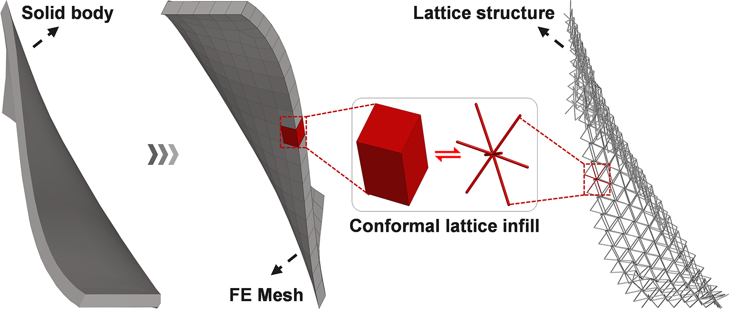
Figure 9: Modeling workflow for a conformally lattice-infilled turbine blade: From left to right: solid model of the turbine blade, finite element mesh discretization, and conformal 3D lattice infill structure.
As shown in Fig. 10, the initial lattice configurations under four build directions are displayed; struts exceeding the manufacturing-angle limit are highlighted in red (“over-limit struts”), confirming the minimum over-limit constraint. This comparison underscores the critical influence of build direction on manufacturability.
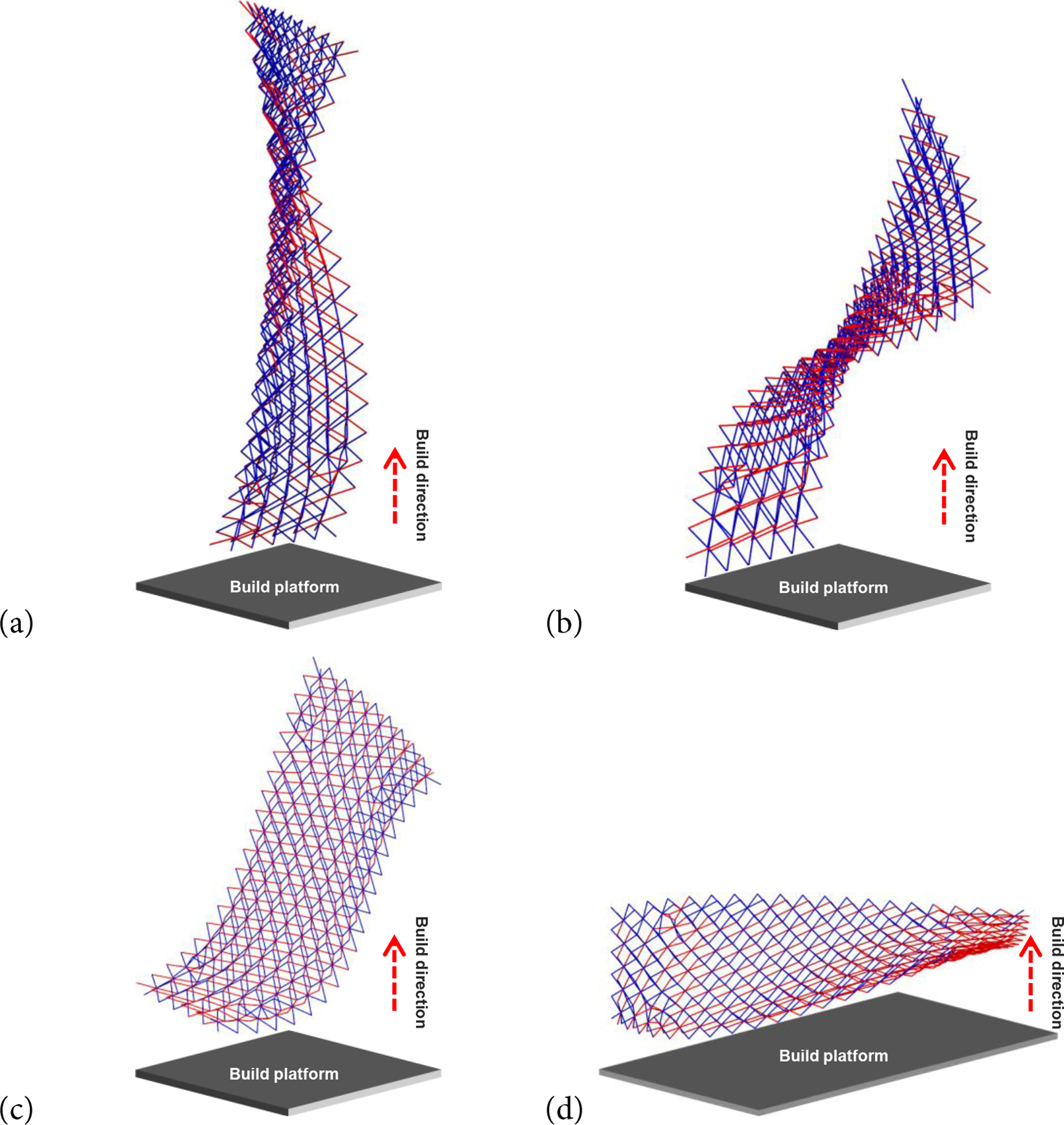
Figure 10: Geometric model of the aeroengine turbine blade. Initial configuration of the conformal lattice infill structure of a certain model of aeroengine turbine blade (Total number of struts: 1008): (a) Build direction (−1.0, 0.6, −0.1), over-limit struts: 313 (31%); (b) Build direction (1.0, 0.0, 0.0), over-limit struts: 428 (42%); (c) Build direction (0.0, 1.0, 0.0), over-limit struts: 490 (49%); (d) Build direction (0.0, 0.0, 1.0), over-limit struts: 592 (59%).
As shown in Fig. 11, the initial designs under all four build directions contain numerous struts that violate the manufacturing-angle constraint. The proposed optimization is then applied to each direction, with global nodal adjustments under a consistent angular limit (maximum nodal displacement fixed at 0.8 mm) to evaluate adaptability on complex boundaries and high-curvature geometries. After optimization, the case with build vector (1.0, 0.0, 0.0) still retains a small set of over-limit struts due to the stringency of the angle constraint, whereas the other three directions effectively eliminate the initial over-limit regions. In all cases, the strut orientations are brought into the manufacturable range while preserving structural continuity and the overall geometry, demonstrating constraint convergence and geometric fidelity under complex shapes.
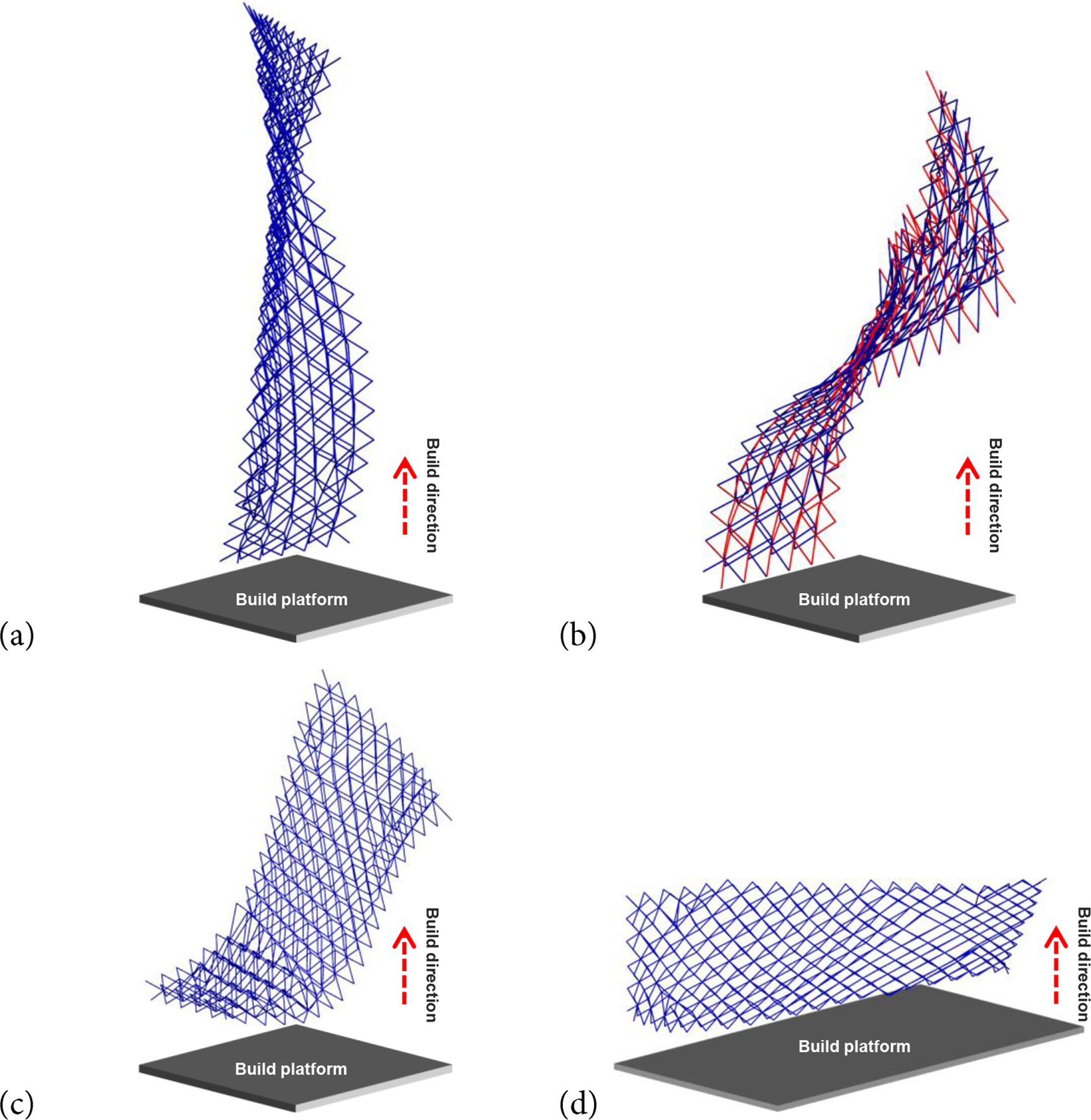
Figure 11: Optimization results under different build directions: (a) (−1.0, 0.6, −0.1), over-limit struts after optimization: 0 (0%); (b) (1.0, 0.0, 0.0), over-limit struts after optimization: 218 (21.6%); (c) (0.0, 1.0, 0.0), over-limit struts after optimization: 0 (0%); (d) (0.0, 0.0, 1.0), over-limit struts after optimization: 0 (0%).
To further quantitatively evaluate the effectiveness of angle optimization, Figs. 12–15 present histograms and line plots of strut angle distributions before and after optimization across the four build directions. Results indicate that prior to optimization, a substantial number of struts exceeded the manufacturable angle range for all build directions. This issue was particularly severe for the Y-axis and Z-axis orientations, where over-limit struts accounted for 48.61% and 58.73%, respectively, significantly impairing structural manufacturability. Post-optimization, strut angle distributions for all build directions became notably concentrated within the manufacturable range. The originally dispersed angle distribution shifted toward the allowable boundaries, demonstrating strong angle compression capability and enhancing overall structural manufacturability.
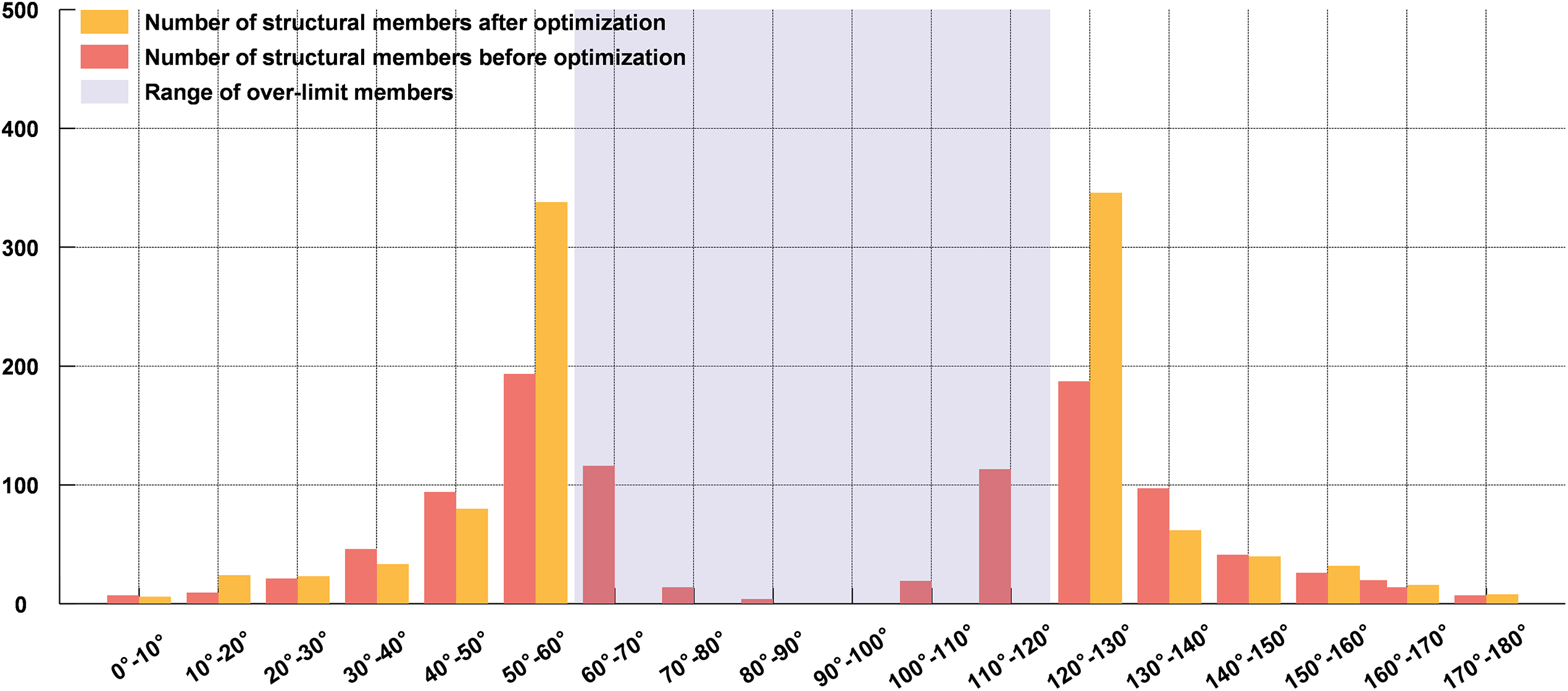
Figure 12: Strut angle distribution before and after optimization for the build direction (−1.0, 0.6, −0.1).
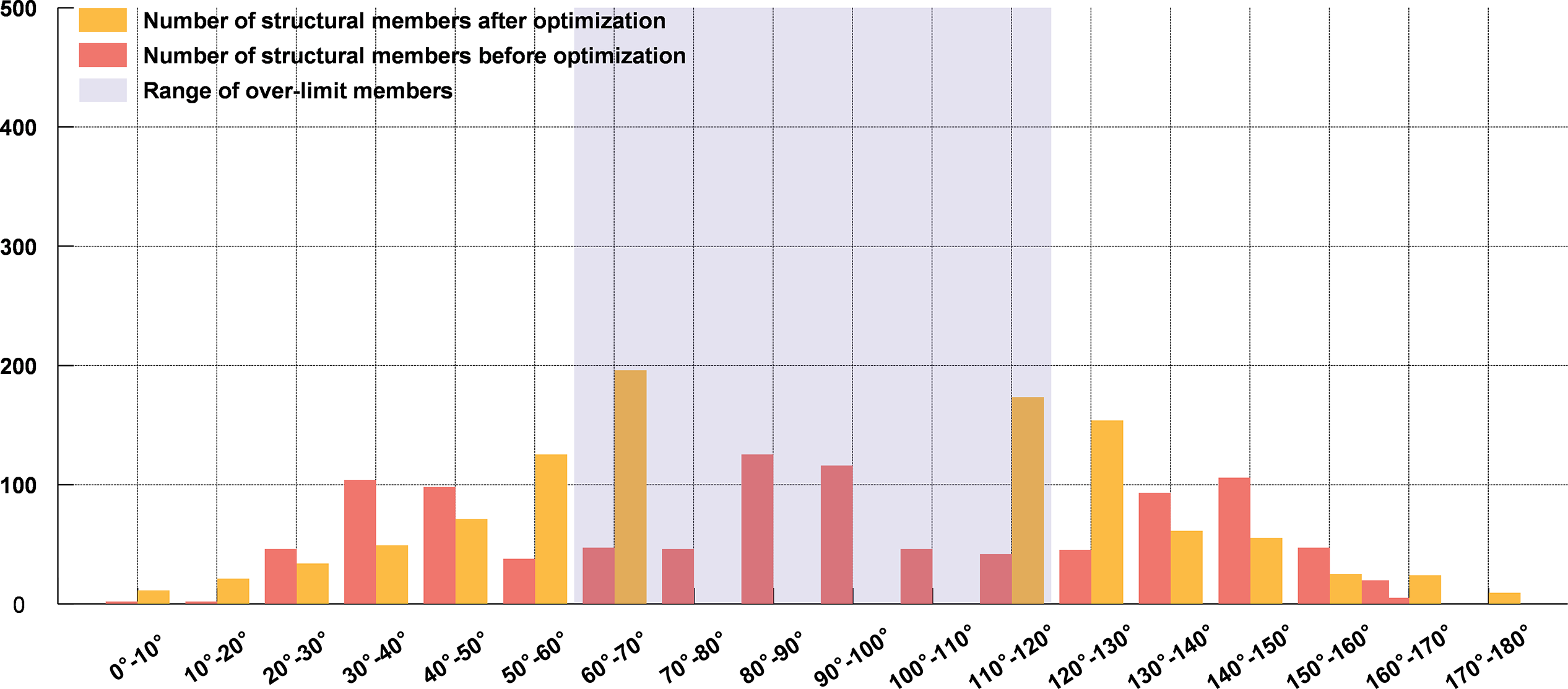
Figure 13: Strut angle distribution before and after optimization for the build direction (1.0, 0.0, 0.0).
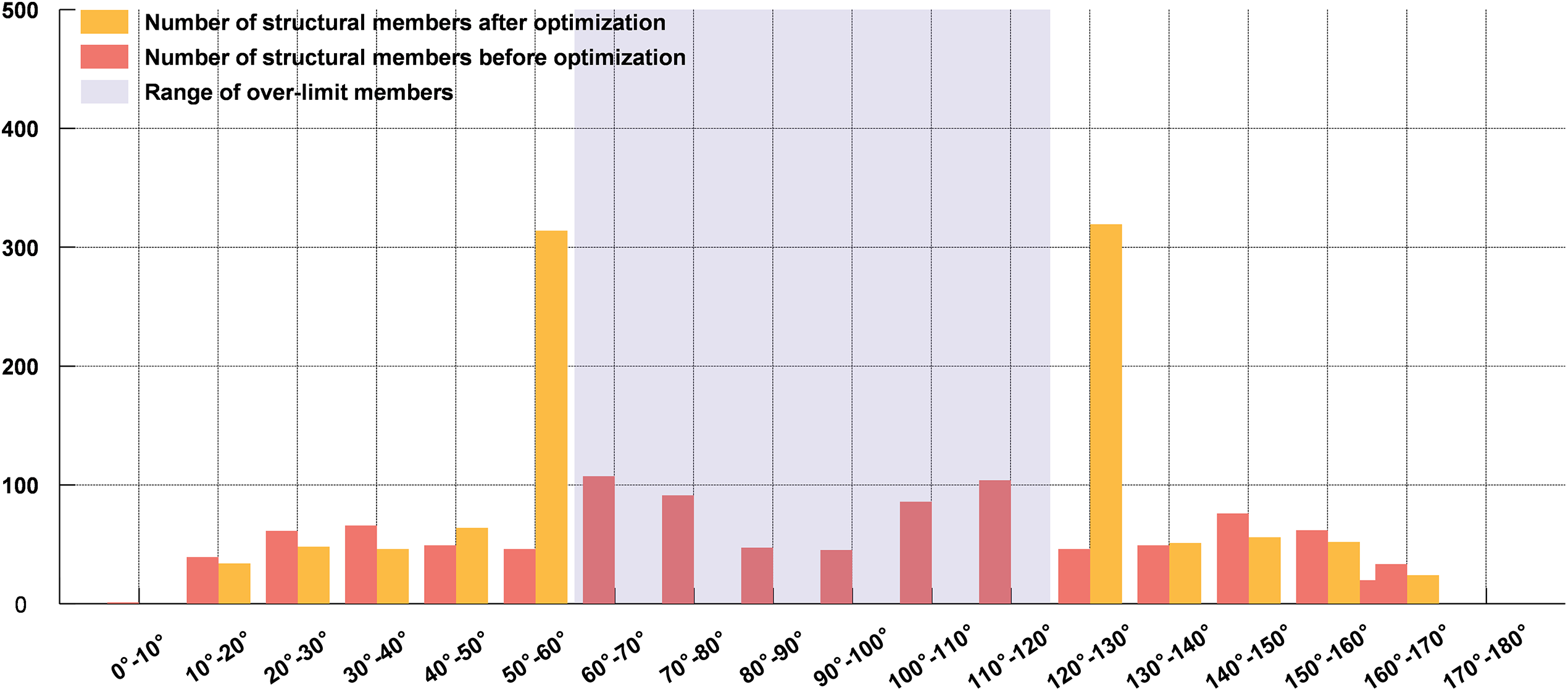
Figure 14: Strut angle distribution before and after optimization for the build direction (0.0, 1.0, 0.0).
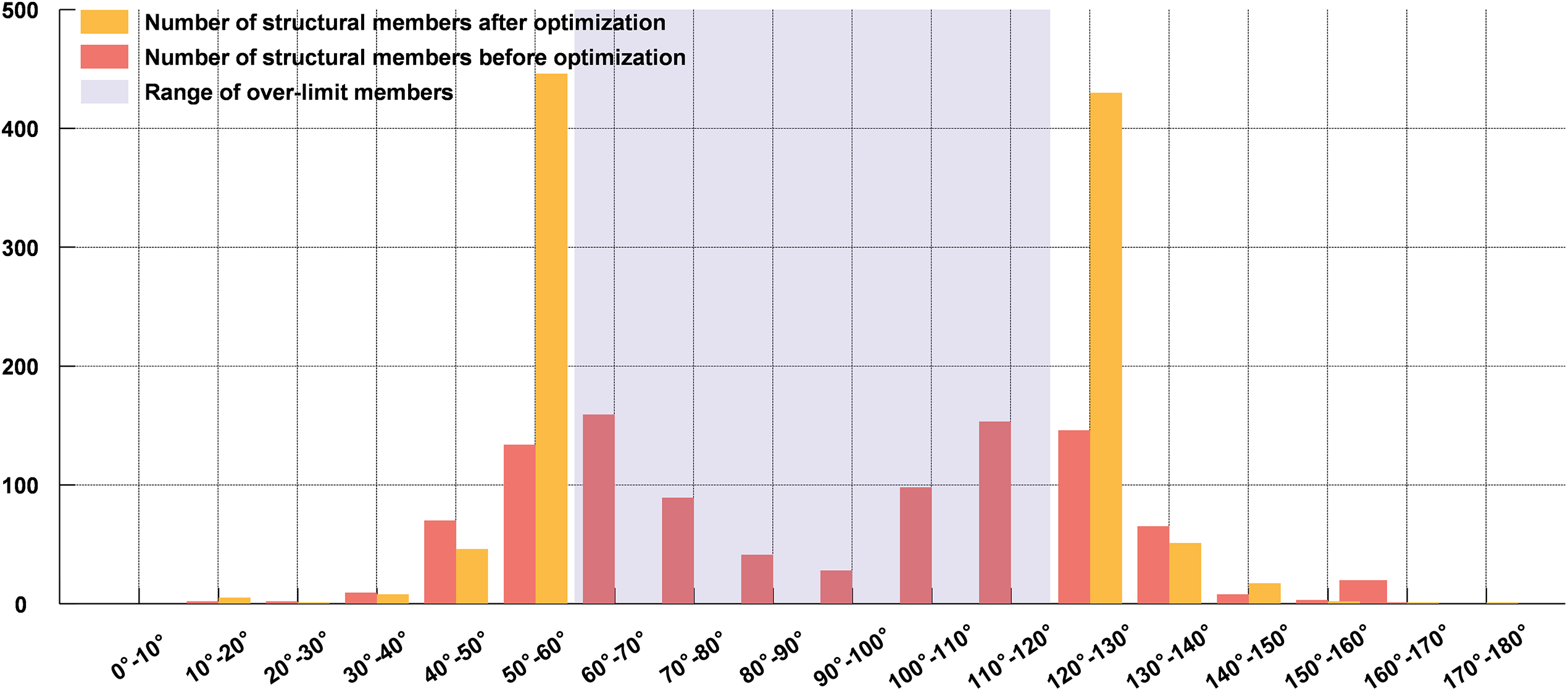
Figure 15: Strut angle distribution before and after optimization for the build direction (0.0, 0.0, 1.0).
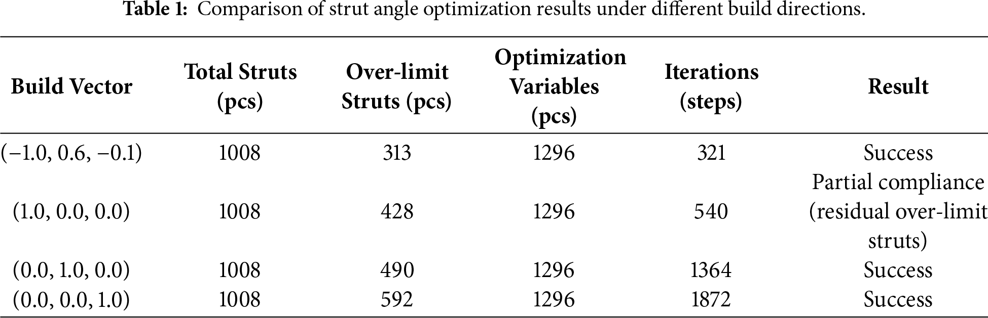
Table 1 summarizes the optimization outcomes for the four build directions, including the number of over-limit struts before and after optimization, the over-limit ratio, and the angle constraint satisfaction rate. The results indicate that, except for the build direction (1.0, 0.0, 0.0), the over-limit ratios for the other three directions were reduced from over 40% to 0% after optimization. The build direction along the minimum over-limit vector (−1.0, 0.6, −0.1) exhibited the best performance, with only 313 over-limit struts initially. The optimization converged efficiently, demonstrating high convergence performance and strong adaptability to manufacturability constraints. In contrast, the Y-axis and Z-axis build directions exhibited higher initial over-limit ratios, resulting in a greater number of iterations required for convergence and increased optimization complexity. For the (1.0, 0.0, 0.0) case, although the over-limit ratio was reduced from 42.46% to 21.6%, the optimization could not fully eliminate all over-limit struts. This outcome is attributed to the small angle between this build direction and the surface normal, which causes a substantial portion of struts to initially lie outside the manufacturable range. Consequently, a large number of design variables required significant adjustments, making convergence more challenging.
In summary, the proposed Angle-Constrained Optimization method demonstrates strong robustness and adaptability across various build directions. Even in complex structural scenarios with high initial over-limit ratios, it can achieve stable convergence. This makes it suitable for manufacturability design of high-complexity conformal lattice structures.
4.3 Case 2: An Ergonomic Sports Insole
To further verify the applicability of the proposed angle-constrained optimization method in multi-region, multi-scale biological structures, an ergonomic sports insole with typical functional zoning was selected as the research object, as shown in Fig. 16. This insole integrates multiple functions such as arch support, forefoot cushioning, and heel stability. It features complex geometric morphology with significant local curvature variations, which imposes higher performance requirements on both manufacturing accuracy and mechanical response.
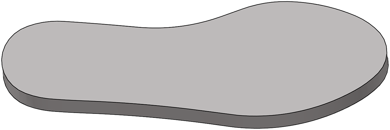
Figure 16: Ergonomic sports insole structure schematic.
The insole surface was non-uniformly meshed using geometry-adaptive modeling, resulting in a total of 402 nodes and 220 elements. Based on the self-developed parametric design platform, the in-house Body-Centered Cubic-Modified Lattice (BCCML)unit cell was adopted as the fundamental topological configuration. A total of 220 periodic unit cells were deployed, forming a Conformal Lattice Structure consisting of 1722 nodes and 3800 struts (Fig. 17). High-function areas (such as the arch and forefoot) were filled with high-density lattices to enhance structural support performance, while low-function areas were filled with moderate density to balance material savings and stiffness matching. Additionally, a uniform allowable overhang-angle domain is applied to all struts, where the two threshold angles are set to
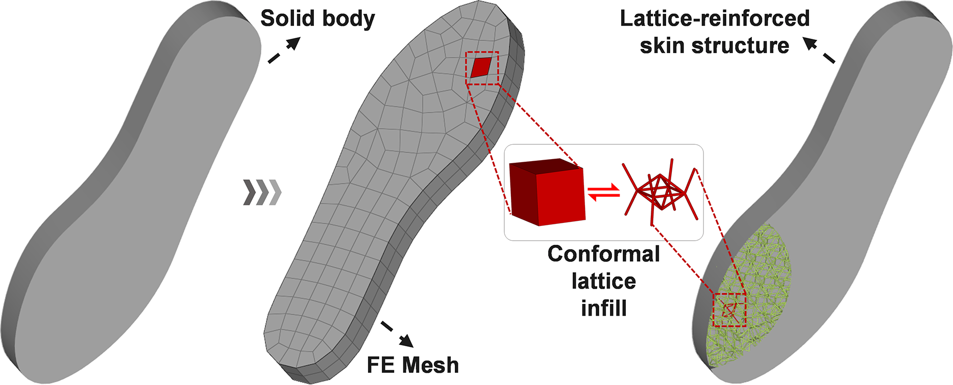
Figure 17: Lattice infill modeling workflow for an ergonomic sports insole: From left to right: solid model of the insole, finite element mesh discretization, and conformal 3D lattice infill structure.
To enhance the manufacturability of the structure, a model using the Angle-Constrained Optimization method with nodal displacement was constructed, with the build direction set as (0.0, 1.0, 0.0) for analysis. Initial identification results revealed that 968 struts violated the allowable angular range, accounting for 25.47% of the total. These over-limit struts, highlighted in red, were mainly concentrated in regions with sharp geometric variations, which can significantly impact the forming stability and surface quality in additive manufacturing (Fig. 18).
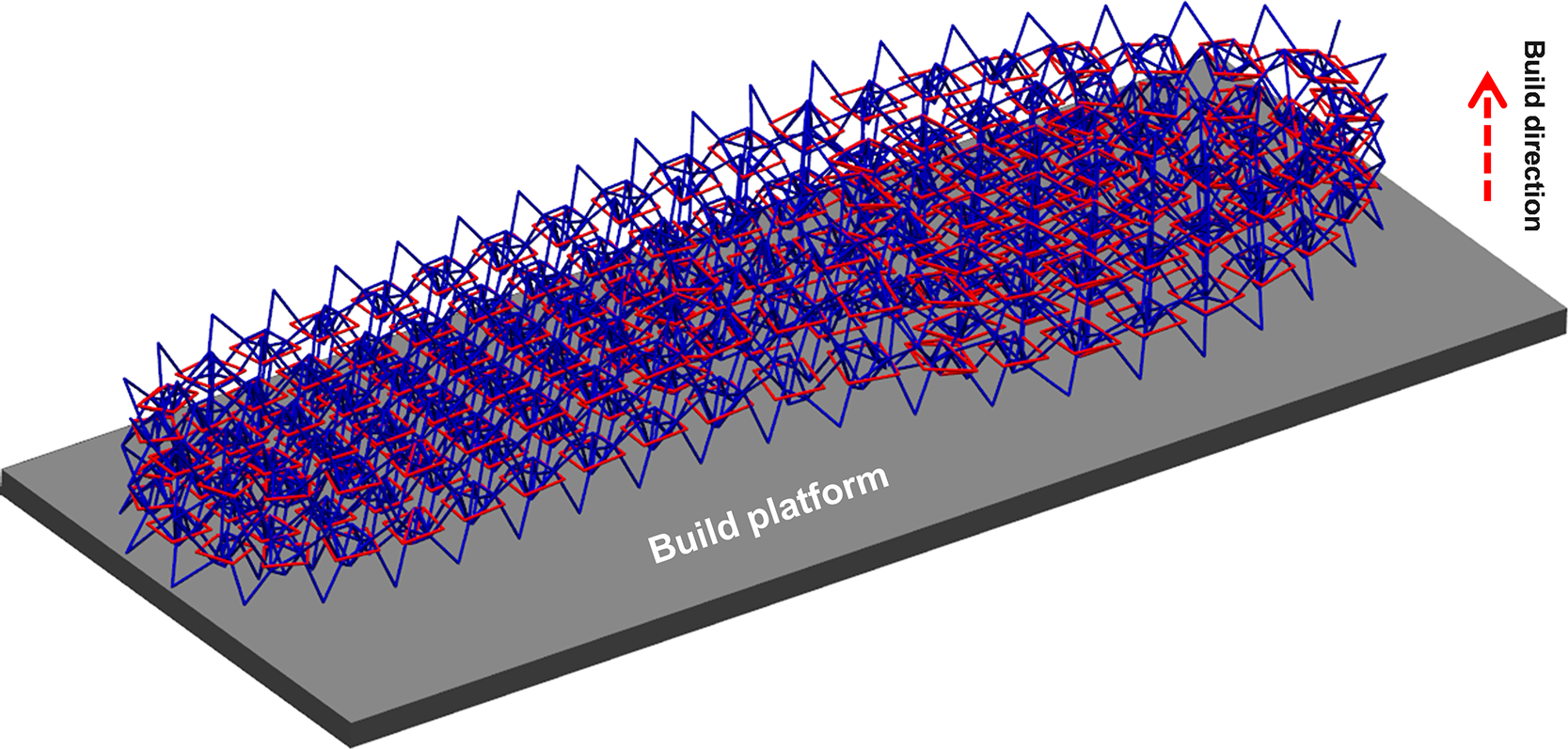
Figure 18: Initial configuration of conformal lattice-filled ergonomic sports insole (before optimization): build direction (0.0, 1.0, 0.0), total struts = 3800, over-limit struts = 968, over-limit ratio = 25.47%.
During the optimization process, a fixed-boundary strategy was adopted by constraining 737 surface nodes of the insole, while optimizing the remaining 985 internal nodes. Each node possesses three degrees of freedom, resulting in a total of 2955 optimization variables and 8800 angular constraints. The nonlinear constrained optimization problem was solved using the trust-constr algorithm, integrated with modules for angular constraint enforcement, gradient filtering, geometric conflict avoidance, and local stiffness adjustment. The final results show that all strut orientations were successfully adjusted into the manufacturable angular domain, reducing the number of over-limit struts from 968 to zero (Fig. 19), while ensuring full conformity between the lattice and the skin (Fig. 20), thereby validating the accuracy and constraint-convergence performance of the proposed method.
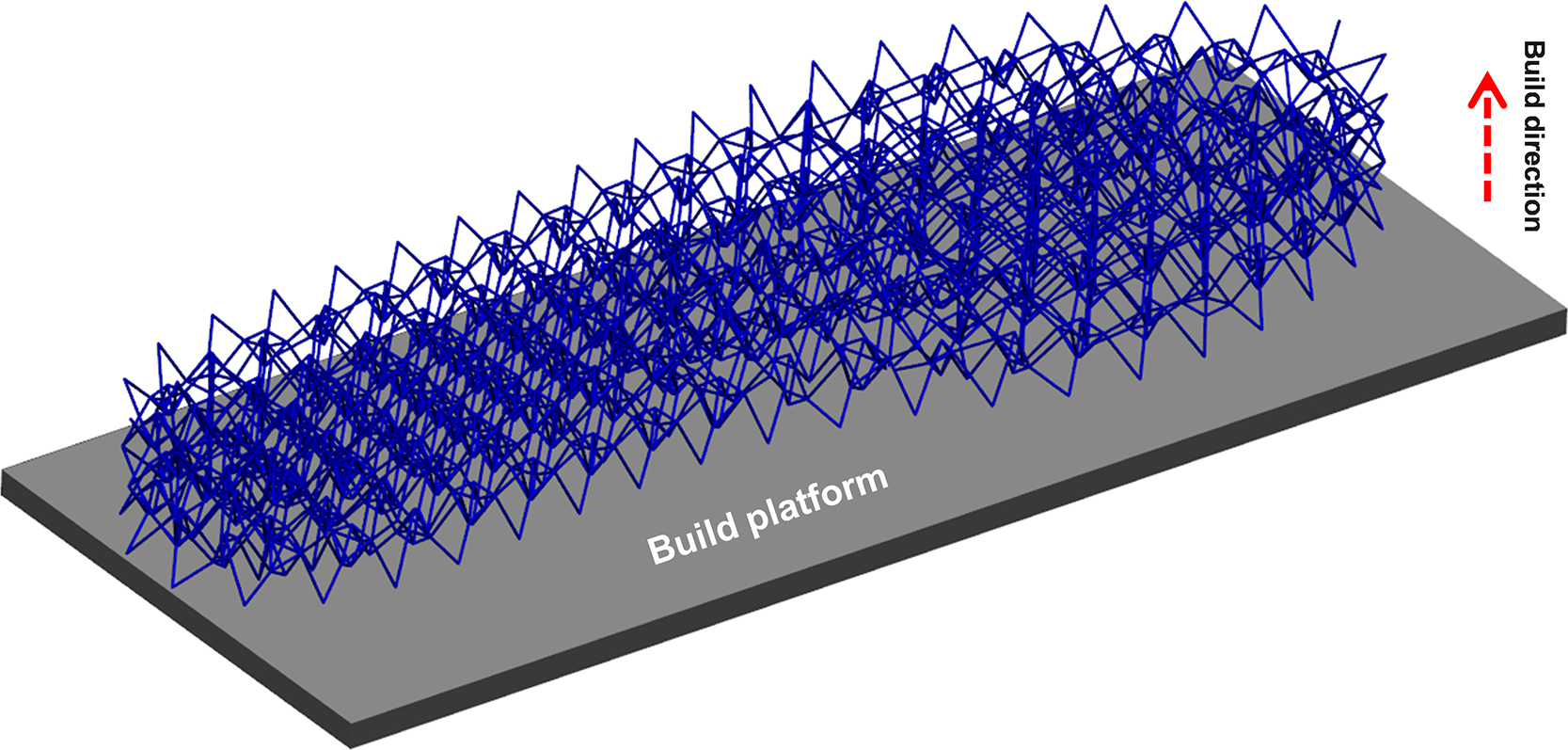
Figure 19: Optimization Results of the Conformal Lattice-Filled Structure for the Ergonomic Insole (after optimization): build direction (0.0, 1.0, 0.0), total struts = 3800, over-limit struts = 0, over-limit ratio = 0%.
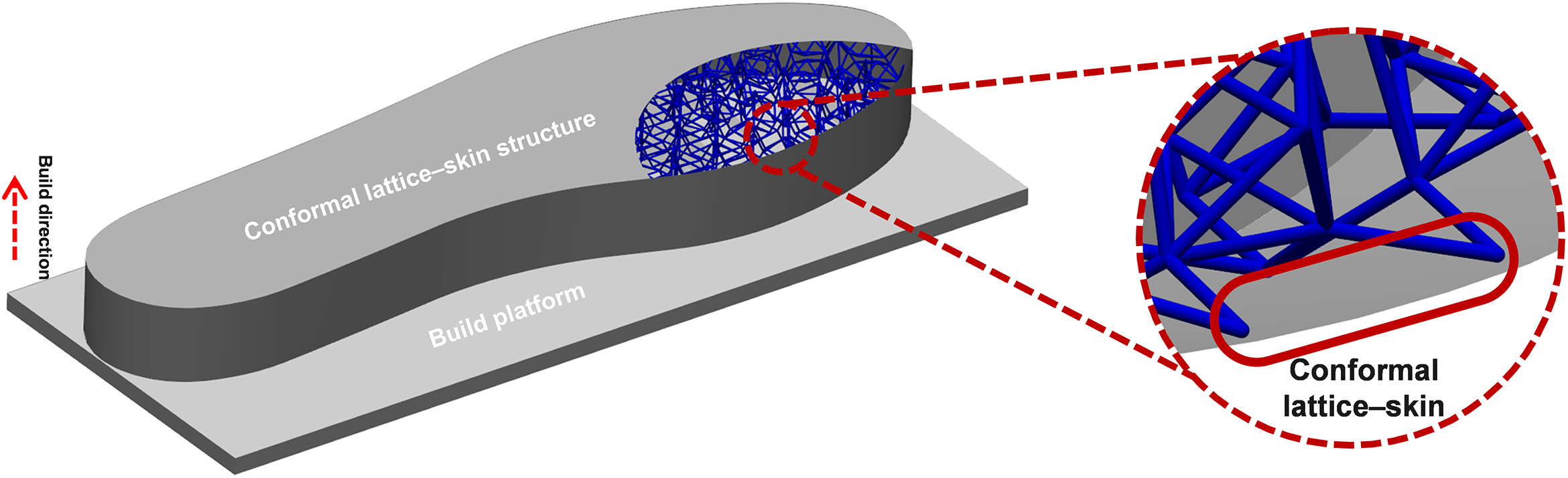
Figure 20: Verification of lattice–skin conformity in the optimized ergonomic insole.
To further quantify the optimization effect, Figs. 21 and 22 present the histograms and line charts of strut angle distribution before and after optimization. The results indicate that before optimization, a large proportion of struts fell into the non-manufacturable range; after optimization, the angle distribution was entirely modified to the manufacturable interval, with significantly improved concentration. These findings highlight the excellent angular regulation and compression capability of the proposed method. In summary, the proposed angle-constrained optimization method can significantly improve the manufacturing compliance of struts while preserving the overall geometric features, and maintain good convergence stability and geometric control capability in multi-scale complex configurations. Combined with validation on both aerospace and flexible components, the method exhibits strong generality and potential for engineering application.
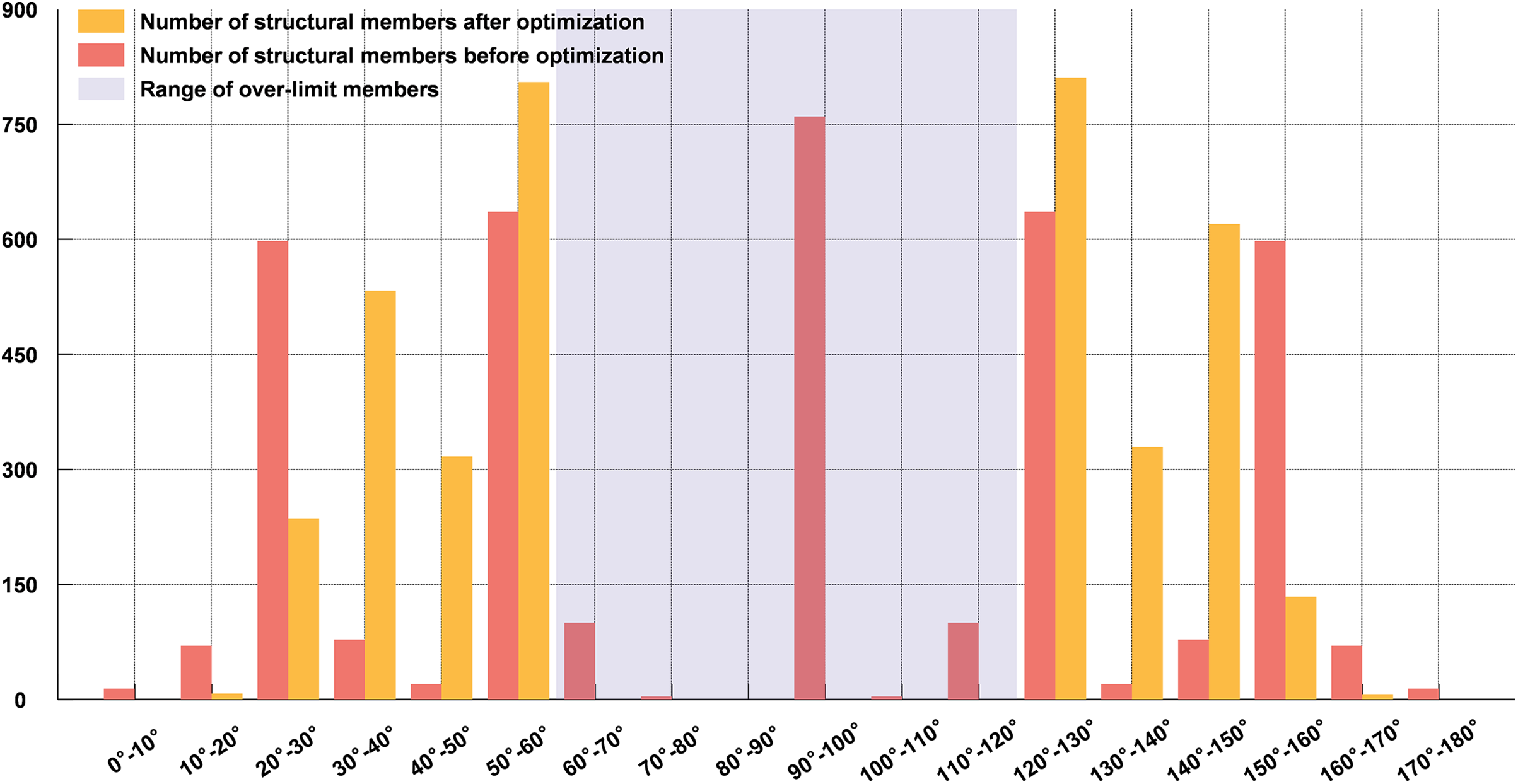
Figure 21: Strut angle distribution before and after optimization for the build direction (0.0, 1.0, 0.0).
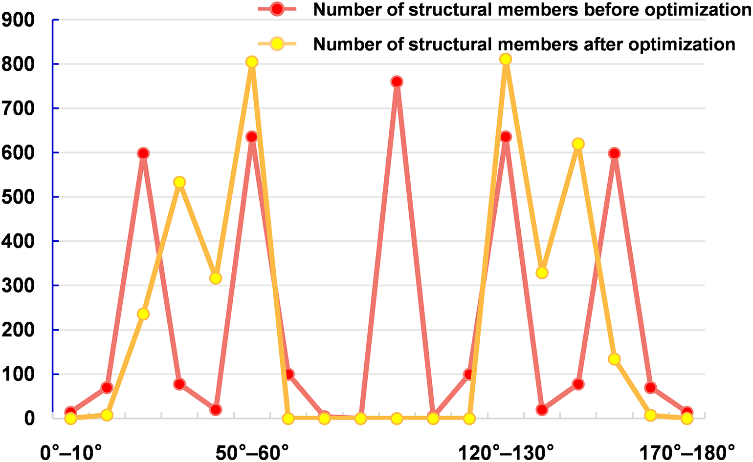
Figure 22: Strut angle distribution curves before and after optimization for the build direction (0.0, 1.0, 0.0).
4.3.3 Consistency of Structural Response before and after Angle-Constrained Adjustment
This section focuses on the sports insole from Case Study 2 as the research subject, and the finite element model is constructed accordingly. Specifically, all finite element simulations are conducted in Abaqus/Standard 2017. The struts of the internal lattice are modeled using B31 beam elements with a circular cross-section of radius
It is worth noting that although the lattice is geometrically truss-like, beam elements are used in the analysis to capture the bending effects of slender struts in curved conformal layouts, while maintaining acceptable computational cost. Since beam models do not resolve local joint stress concentration as solid models do, the stress discussion focuses on overall distribution patterns and peak-value trends.
Under the aforementioned loading conditions, the global deformation patterns of the insole before and after optimization are overall identical (Fig. 23). In both cases, the heel region exhibits a downward deflection accompanied by a smooth transition over the arch and forefoot area, and the cooperative deformation between the skin and the lattice core remains essentially unchanged. No additional regions of localized softening or abnormal deformation are observed in the optimized design.
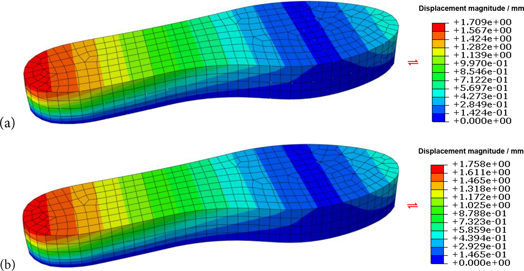
Figure 23: Comparison of displacement magnitude distributions of the ergonomic insole for the applied heel-loading condition: (a) initial lattice; (b) optimized lattice. The maximum displacement changes from 1.709 mm to 1.758 mm, corresponding to a relative variation of 2.87%.
From a quantitative perspective Table 2, the overall maximum vertical displacement of the insole is
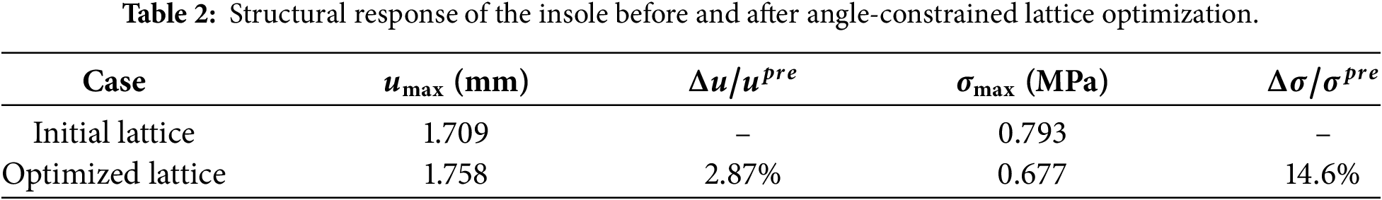
In addition to the displacement comparison, the von Mises stress distribution is examined for both the skin and the internal lattice under the same loading and boundary conditions. The high-stress region remains mainly located in the heel area where the load is introduced and transferred into the lattice network, while the optimized design shows a reduced stress peak and a smoother stress gradient along the load-transfer path. From a quantitative perspective (Table 2), the peak von Mises stress of the internal lattice is
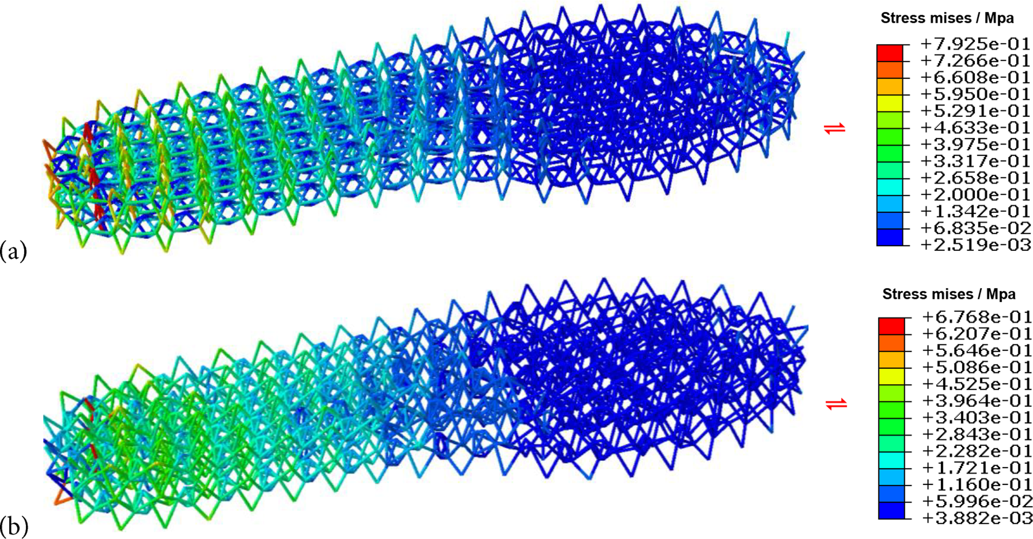
Figure 24: Von Mises stress contours of the ergonomic insole under the same heel-loading condition: (a) initial lattice; (b) optimized lattice. The maximum von Mises stress changes from 0.793 MPa to 0.677 MPa, corresponding to a relative variation of 14.6%.
This study proposed a global framework of the Angle-Constrained Optimization method based on nodal coordinate adjustment to address the manufacturability challenges of lattice structures in additive manufacturing. The method embeds overhang angle constraints directly into the design stage and combines sensitivity-guided mechanisms with trust-region constrained solvers, enabling the automatic identification and adjustment of over-limit struts while preserving structural fidelity.
Several important findings were revealed through numerical case studies. First, the manufacturability of conformal lattices is highly sensitive to the choice of build direction: different orientations result in markedly different proportions of over-limit struts, which in turn strongly affect optimization efficiency and convergence behavior. Second, a clear distinction exists between free-boundary and surface-constrained scenarios. For free-boundary designs, the algorithm shows strong adaptability and can achieve full compliance. In contrast, when surface conformity constraints are imposed, the feasible design space is reduced, improving geometric consistency with external skins but increasing sensitivity to the initial violation ratio and prolonging convergence time. Third, although the method successfully eliminated all over-limit struts under most build directions, certain unfavorable orientations still resulted in residual violations, indicating that some intrinsic geometric limitations cannot be fully resolved by optimization alone.
In addition to geometric compliance, this study also quantitatively evaluated the structural response consistency of the ergonomic insole before and after the angle-constrained adjustment under identical loading and boundary conditions. The overall maximum vertical displacement increased from 1.709 mm to 1.758 mm, corresponding to a 2.87% increase. The peak von Mises stress of the internal lattice decreased from 0.793 to 0.677 under the same unit system. Moreover, the overall stress and displacement distributions remained largely consistent before and after optimization. These results demonstrate that the proposed angle-constrained adjustment method has a minimal impact on stiffness but a more significant impact on strength, while still meeting the requirements for additive manufacturing.
Overall, these findings demonstrate that the proposed approach is robust across diverse geometric configurations and constraint scenarios, effectively balancing manufacturability, geometric fidelity, and computational efficiency. Its capability to adapt to both free and constrained boundary conditions highlights its applicability to highly complex engineering problems, such as curved surfaces, graded lattice layouts, and multi-functional regions. Considering the limitations of the current method, future work will focus on (i) physical printing validation and post-processing assessment; and (ii) extending the framework toward multi-objective optimization, jointly considering manufacturability constraints, mechanical performance, and actual printing cost factors, thereby further advancing the integrated treatment of design intent, additive-manufacturing constraints, and structural performance.
Acknowledgement: None.
Funding Statement: This work was supported by the National Natural Science Foundation of China (Grant Nos. 12432005 and 12472116) and the Fundamental Research Funds for the Central Universities (DUTZD25240).
Author Contributions: The authors confirm contribution to the paper as follows: study conception and design: Jun Yan, Kun Yan, Weibin Xu; data collection: Weibin Xu, Fuhao Wang, Sixu Huo; analysis and interpretation of results: Jun Yan, Kun Yan, Weibin Xu, Sixu Huo; draft manuscript preparation: Weibin Xu and Kun Yan. All authors reviewed and approved the final version of the manuscript
Availability of Data and Materials: No dataset was used for the research described in the article.
Ethics Approval: Not applicable.
Conflicts of Interest: The authors declare no conflicts of interest.
Nomenclature
| Symbol | Description Unit |
| e | Index of strut - |
| k | Index of moveable nodes - |
| The first and second end nodes of the e-th strut mm (millimeters) | |
| The three-dimensional coordinates of nodes ni and nj mm (millimeters) | |
| Direction vector of the e-th strut - | |
| Unit direction vector of the e-th strut - | |
| Euclidean norm (magnitude) of De - | |
| Overhang angle between the e-th strut orientation and the build direction degrees (°) | |
| The total number of struts - | |
| The build direction - | |
| Euclidean norm (magnitude) of | |
| Euclidean norm (magnitude) of | |
| The cosine values of the overhang angles | |
| The directional-cosine matrix - | |
| The overhang-angle matrix - | |
| The two boundary overhang angles degrees (°) | |
| Strut-wise allowable angular-bound matrix - | |
| The number of moveable (effective) nodes - | |
| Objective function in optimization - | |
| Vector of coordinate changes for all moveable nodes mm (millimeters) | |
| 3D coordinate-change (increment) vector of the k-th moveable node: mm (millimeters) | |
| Overhang angle of the strut after nodal update degrees (°) | |
| Upper bound on the maximum component-wise nodal movement mm (millimeters) | |
| The sensitivity of the overhang angle between the e-th strut direction vector and the build direction with respect to the coordinate of the k-th moveable node - | |
| Strut angle violation ratio % | |
| The number of struts that violate the overhang-angle constraint - | |
| Radius of the beam element cross-section mm (millimeters) | |
| The thickness of the shell mm (millimeters) | |
| Density of the material (TPU) t/mm³ (tonnes per cubic millimeter) | |
| Young’s modulus of the material (TPU) MPa (megapascals) | |
| Poisson’s ratio of the material (TPU) - | |
| Maximum vertical displacement mm (millimeters) | |
| Maximum vertical displacement for the initial lattice (pre) mm (millimeters) | |
| Maximum vertical displacement for the optimized lattice (post) mm (millimeters) | |
| Maximum von Mises stress MPa (megapascals) | |
| Maximum von Mises stress for the initial lattice (pre) MPa (megapascals) | |
| Maximum von Mises stress for the optimized lattice (post) MPa (megapascals) | |
| Relative variation in maximum vertical displacement - | |
| Relative variation in maximum von Mises stress - |
References
1. Zhang X, Yao J, Liu B, Yan J, Lu L, Li Y, et al. Three-dimensional high-entropy alloy-polymer composite nanolattices that overcome the strength-recoverability trade-off. Nano Lett. 2018;18(7):4247–56. doi:10.1021/acs.nanolett.8b01241. [Google Scholar] [PubMed] [CrossRef]
2. Jia Z, Liu F, Jiang X, Wang L. Engineering lattice metamaterials for extreme property, programmability, and multifunctionality. J Appl Phys. 2020;127(15):150901. doi:10.1063/5.0004724. [Google Scholar] [CrossRef]
3. Sookchanchai K, Promoppatum P, Uthaisangsuk V. Load-carrying capacity of additively manufactured part using graded-topology infilled lattices structures. Mech Adv Mater Struct. 2024;31(6):1313–31. doi:10.1080/15376494.2022.2135145. [Google Scholar] [CrossRef]
4. Zhu X, Ma S, Zhang H, Lu G, Zhou H. Design and energy absorption of star-shaped nesting cells and gradient lattice structures with negative Poisson’s ratio effect. Mech Adv Mater Struct. 2024;31(27):9073–87. doi:10.1080/15376494.2023.2265359. [Google Scholar] [CrossRef]
5. Khosroshahi SF, Tsampas SA, Galvanetto U. Feasibility study on the use of a hierarchical lattice architecture for helmet liners. Mater Today Commun. 2018;14:312–23. doi:10.1016/j.mtcomm.2018.02.002. [Google Scholar] [CrossRef]
6. Wang Y, Zhao Q, Li G, Li X. Mechanical performance of additive manufactured TPMS lattice structures based on topology optimization. Comput Model Eng Sci. 2025;144(1):763–89. doi:10.32604/cmes.2025.067363. [Google Scholar] [CrossRef]
7. Ahuja B, Karg M, Schmidt M. Additive manufacturing in production: challenges and opportunities. Laser 3D Manuf II. 2015;9353:11–20. doi:10.1117/12.2082521. [Google Scholar] [CrossRef]
8. Wu J, Wang W, Gao X. Design and optimization of conforming lattice structures. IEEE Trans Vis Comput Graph. 2021;27(1):43–56. doi:10.1109/TVCG.2019.2938946. [Google Scholar] [PubMed] [CrossRef]
9. Wang D, Yang Y, Wang Y, Yang L, Wang H, Yang S. Introduction to the special issue on design and simulation in additive manufacturing. Comput Model Eng Sci. 2021;126(1):1–4. doi:10.32604/cmes.2021.015180. [Google Scholar] [CrossRef]
10. Wang D, Ye G, Mai J, Chen X, Yang Y, Li Y, et al. Novel micromixer with complex 3D-shape inner units: design, simulation and additive manufacturing. Comput Model Eng Sci. 2020;123(3):1061–77. doi:10.32604/cmes.2020.09842. [Google Scholar] [CrossRef]
11. Li Y, Tang K, He D, Wang X. Multi-axis support-free printing of freeform parts with lattice infill structures. Comput Aided Des. 2021;133:102986. doi:10.1016/j.cad.2020.102986. [Google Scholar] [CrossRef]
12. Gaynor AT, Guest JK. Topology optimization considering overhang constraints: eliminating sacrificial support material in additive manufacturing through design. Struct Multidiscip Optim. 2016;54(5):1157–72. doi:10.1007/s00158-016-1551-x. [Google Scholar] [CrossRef]
13. Liu J, Gaynor AT, Chen S, Kang Z, Suresh K, Takezawa A, et al. Current and future trends in topology optimization for additive manufacturing. Struct Multidiscip Optim. 2018;57(6):2457–83. doi:10.1007/s00158-018-1994-3. [Google Scholar] [CrossRef]
14. Xia Z, He Z, Wang Q, Wang Y. A new finite element model with manufactured error for additive manufacturing. Comput Model Eng Sci. 2020;124(2):703–20. doi:10.32604/cmes.2020.010368. [Google Scholar] [CrossRef]
15. Jiang J, Xu X, Stringer J. Support structures for additive manufacturing: a review. J Manuf Mater Process. 2018;2(4):64. doi:10.3390/jmmp2040064. [Google Scholar] [CrossRef]
16. Hussein A, Hao L, Yan C, Everson R, Young P. Advanced lattice support structures for metal additive manufacturing. J Mater Process Technol. 2013;213(7):1019–26. doi:10.1016/j.jmatprotec.2013.01.020. [Google Scholar] [CrossRef]
17. Wang Z, Zhang Y, Tan S, Ding L, Bernard A. Support point determination for support structure design in additive manufacturing. Addit Manuf. 2021;47(2):102341. doi:10.1016/j.addma.2021.102341. [Google Scholar] [CrossRef]
18. Langelaar M. Combined optimization of part topology, support structure layout and build orientation for additive manufacturing. Struct Multidiscip Optim. 2018;57(5):1985–2004. doi:10.1007/s00158-017-1877-z. [Google Scholar] [CrossRef]
19. Qian X. Undercut and overhang angle control in topology optimization: a density gradient based integral approach. Int J Numer Meth Eng. 2017;111(3):247–72. doi:10.1002/nme.5461. [Google Scholar] [CrossRef]
20. Liu J, Ma Y. A survey of manufacturing oriented topology optimization methods. Adv Eng Softw. 2016;100(1):161–75. doi:10.1016/j.advengsoft.2016.07.017. [Google Scholar] [CrossRef]
21. Tang Y, Kurtz A, Zhao YF. Bidirectional evolutionary structural optimization (BESO) based design method for lattice structure to be fabricated by additive manufacturing. Comput Aided Des. 2015;69:91–101. doi:10.1016/j.cad.2015.06.001. [Google Scholar] [CrossRef]
22. Wu J, Wang CCL, Zhang X, Westermann R. Self-supporting rhombic infill structures for additive manufacturing. Comput Aided Des. 2016;80(4):32–42. doi:10.1016/j.cad.2016.07.006. [Google Scholar] [CrossRef]
23. Zou J, Mou H. Topology optimization of self-supporting structures for additive manufacturing with adaptive explicit continuous constraint. Comput Model Eng Sci. 2022;132(2):451–69. doi:10.32604/cmes.2022.020111. [Google Scholar] [CrossRef]
24. Tang Y, Dong G, Zhou Q, Zhao YF. Lattice structure design and optimization with additive manufacturing constraints. IEEE Trans Autom Sci Eng. 2018;15(4):1546–62. doi:10.1109/TASE.2017.2685643. [Google Scholar] [CrossRef]
25. Khan N, Riccio A. A systematic review of design for additive manufacturing of aerospace lattice structures: current trends and future directions. Prog Aerosp Sci. 2024;149(2):101021. doi:10.1016/j.paerosci.2024.101021. [Google Scholar] [CrossRef]
26. Langelaar M. An additive manufacturing filter for topology optimization of print-ready designs. Struct Multidiscip Optim. 2017;55(3):871–83. doi:10.1007/s00158-016-1522-2. [Google Scholar] [CrossRef]
27. Fu YF, Rolfe B, Chiu LNS, Wang Y, Huang X, Ghabraie K. Design and experimental validation of self-supporting topologies for additive manufacturing. Virtual Phys Prototyp. 2019;14(4):382–94. doi:10.1080/17452759.2019.1637023. [Google Scholar] [CrossRef]
28. Fu YF, Rolfe B, Chiu LNS, Wang Y, Huang X, Ghabraie K. Parametric studies and manufacturability experiments on smooth self-supporting topologies. Virtual Phys Prototyp. 2020;15(1):22–34. doi:10.1080/17452759.2019.1644185. [Google Scholar] [CrossRef]
29. Liu J, To AC. Deposition path planning-integrated structural topology optimization for 3D additive manufacturing subject to self-support constraint. Comput Aided Des. 2017;91:27–45. doi:10.1016/j.cad.2017.05.003. [Google Scholar] [CrossRef]
30. Wang Y, Gao J, Kang Z. Level set-based topology optimization with overhang constraint: towards support-free additive manufacturing. Comput Methods Appl Mech Eng. 2018;339:591–614. doi:10.1016/j.cma.2018.04.040. [Google Scholar] [CrossRef]
31. Han YS, Xu B, Zhao L, Xie YM. Topology optimization of continuum structures under hybrid additive-subtractive manufacturing constraints. Struct Multidisc Optim. 2019;60(6):2571–95. doi:10.1007/s00158-019-02334-3. [Google Scholar] [CrossRef]
32. Bi M, Tran P, Xie YM. Topology optimization of 3D continuum structures under geometric self-supporting constraint. Addit Manuf. 2020;36:101422. doi:10.1016/j.addma.2020.101422. [Google Scholar] [CrossRef]
33. Guo X, Zhou J, Zhang W, Du Z, Liu C, Liu Y. Self-supporting structure design in additive manufacturing through explicit topology optimization. Comput Meth Appl Mech Eng. 2017;323:27–63. doi:10.1016/j.cma.2017.05.003. [Google Scholar] [CrossRef]
34. Zhou L, Sigmund O, Zhang W. Self-supporting structure design with feature-driven optimization approach for additive manufacturing. Comput Meth Appl Mech Eng. 2021;386:114110. doi:10.1016/j.cma.2021.114110. [Google Scholar] [CrossRef]
35. Liu F, Chen M, Wang L, Luo T, Chen G. Stress-field driven conformal lattice design using circle packing algorithm. Heliyon. 2023;9(3):e14448. doi:10.1016/j.heliyon.2023.e14448. [Google Scholar] [PubMed] [CrossRef]
36. Liu F, Chen M, Wang L, Xiang Z, Huang S. Lightweight and customized design via conformal parametric lattice driven by stress fields. In: Phygital intelligence. Singapore: Springer Nature; 2024. p. 139–49. doi:10.1007/978-981-99-8405-3_12. [Google Scholar] [CrossRef]
37. du Plessis A, Broeckhoven C, Yadroitsava I, Yadroitsev I, Hands CH, Kunju R, et al. Beautiful and functional: a review of biomimetic design in additive manufacturing. Addit Manuf. 2019;27:408–27. doi:10.1016/j.addma.2019.03.033. [Google Scholar] [CrossRef]
38. Acanfora V, Saputo S, Russo A, Riccio A. A feasibility study on additive manufactured hybrid metal/composite shock absorbers. Compos Struct. 2021;268(4):113958. doi:10.1016/j.compstruct.2021.113958. [Google Scholar] [CrossRef]
39. Yan J, Sui Q, Fan Z, Duan Z. Multi-material and multiscale topology design optimization of thermoelastic lattice structures. Comput Model Eng Sci. 2022;130(2):967–86. doi:10.32604/cmes.2022.017708. [Google Scholar] [CrossRef]
40. Yan J, Zhang C, Li X, Xu L, Fan Z, Sun W, et al. Multiscale analysis of bi-layer lattice-filled sandwich structure based on NIAH method. Materials. 2022;15(21):7710. doi:10.3390/ma15217710. [Google Scholar] [PubMed] [CrossRef]
41. Kreide C, Koricho E, Kardel K. Energy absorption of 3D printed multi-material elastic lattice structures. Prog Addit Manuf. 2024;9(6):1653–65. doi:10.1007/s40964-023-00529-1. [Google Scholar] [CrossRef]
42. Li D, Liao W, Dai N, Dong G, Tang Y, Xie YM. Optimal design and modeling of gyroid-based functionally graded cellular structures for additive manufacturing. Comput Aided Des. 2018;104(2):87–99. doi:10.1016/j.cad.2018.06.003. [Google Scholar] [CrossRef]
43. Chougrani L, Pernot JP, Véron P, Abed S. Lattice structure lightweight triangulation for additive manufacturing. Comput Aided Des. 2017;90(1):95–104. doi:10.1016/j.cad.2017.05.016. [Google Scholar] [CrossRef]
44. Pratheesh Kumar S, Elangovan S, Mohanraj R, Ramakrishna JR. Review on the evolution and technology of State-of-the-Art metal additive manufacturing processes. Mater Today Proc. 2021;46(11):7907–20. doi:10.1016/j.matpr.2021.02.567. [Google Scholar] [CrossRef]
45. Bahnini I, Rivette M, Rechia A, Siadat A, Elmesbahi A. Additive manufacturing technology: the status, applications, and prospects. Int J Adv Manuf Technol. 2018;97(1):147–61. doi:10.1007/s00170-018-1932-y. [Google Scholar] [CrossRef]
46. Pan C, Han Y, Lu J. Design and optimization of lattice structures: a review. Appl Sci. 2020;10(18):6374. doi:10.3390/app10186374. [Google Scholar] [CrossRef]
47. Zang T, Zhu D, Mu G. Inverse construction methods of heterogeneous NURBS object based on additive manufacturing. Comput Model Eng Sci. 2020;125(2):597–610. doi:10.32604/cmes.2020.09965. [Google Scholar] [CrossRef]
48. De Weer T, Vannieuwenhoven N, Lammens N, Meerbergen K. The parametrized superelement approach for lattice joint modelling and simulation. Comput Mech. 2022;70(2):451–75. doi:10.1007/s00466-022-02176-9. [Google Scholar] [CrossRef]
49. Huang X, Xiong Y, Zhou M. Concurrent optimization of laser scanning path and structural topology for thermal distortion control in additive manufacturing. Addit Manuf. 2025;114:105046. doi:10.1016/j.addma.2025.105046. [Google Scholar] [CrossRef]
50. Shin S, Goh B, Oh Y, Chung H. Topology optimization for multi-axis additive manufacturing considering overhang and anisotropy. arXiv:2502.20343. 2025. [Google Scholar]
51. Luo Y, Sigmund O, Li Q, Liu S. Additive manufacturing oriented topology optimization of structures with self-supported enclosed voids. Comput Meth Appl Mech Eng. 2020;372(3):113385. doi:10.1016/j.cma.2020.113385. [Google Scholar] [CrossRef]
52. Teke IT, Ertas AH. Fatigue resistance in engineering components: a comprehensive review on the role of geometry and its optimization. Comput Model Eng Sci. 2025;144(1):201–37. doi:10.32604/cmes.2025.066644. [Google Scholar] [CrossRef]
53. Marschall D, Rippl H, Ehrhart F, Schagerl M. Boundary conformal design of laser sintered sandwich cores and simulation of graded lattice cells using a forward homogenization approach. Mater Des. 2020;190(45):108539. doi:10.1016/j.matdes.2020.108539. [Google Scholar] [CrossRef]
54. Yan K, Liu D, Yan J. Topology optimization method for transient heat conduction using the Lyapunov equation. Int J Heat Mass Transf. 2024;231(8):125815. doi:10.1016/j.ijheatmasstransfer.2024.125815. [Google Scholar] [CrossRef]
55. Dal Fabbro P, Rosso S, Ceruti A, Boscolo Bozza D, Meneghello R, Concheri G, et al. Analysis of a preliminary design approach for conformal lattice structures. Appl Sci. 2021;11(23):11449. doi:10.3390/app112311449. [Google Scholar] [CrossRef]
56. Chen JC, Patterson M, Mirzendehdel AM, Behandish M. Automatic shape modification for self-supporting structures in additive manufacturing. In: Proceedings of the ASME 2022 International Design Engineering Technical Conferences and Computers and Information in Engineering Conference; 2022 Aug 14–17; St. Louis, MO, USA. doi:10.1115/DETC2022-89054. [Google Scholar] [CrossRef]
57. Wang C, Qian X, Gerstler WD, Shubrooks J. Boundary slope control in topology optimization for additive manufacturing: for self-support and surface roughness. J Manuf Sci Eng. 2019;141(9):091001. doi:10.1115/1.4043978. [Google Scholar] [CrossRef]
58. Santos SA. Trust-region-based methods for nonlinear programming: recent advances and perspectives. Pesqui Oper. 2014;34(3):447–62. doi:10.1590/0101-7438.2014.034.03.0447. [Google Scholar] [CrossRef]
59. Kraft D. Algorithm 733: TOMP-Fortran modules for optimal control calculations. ACM Trans Math Softw. 1994;20(3):262–81. doi:10.1145/192115.192124. [Google Scholar] [CrossRef]
60. Yan J, Zhang C, Huo S, Chai X, Liu Z, Yan K. Experimental and numerical simulation of bird-strike performance of lattice-material-infilled curved plate. Chin J Aeronaut. 2021;34(8):245–57. doi:10.1016/j.cja.2020.09.026. [Google Scholar] [CrossRef]
Cite This Article
 Copyright © 2026 The Author(s). Published by Tech Science Press.
This work is licensed under a Creative Commons Attribution 4.0 International License , which permits unrestricted use, distribution, and reproduction in any medium, provided the original work is properly cited.
 Downloads
 Citation Tools