
 Submit a Paper
 Propose a Special lssue
 Open Access
ARTICLE
Multiway Relay Based Framework for Network Coding in Multi-Hop WSNs
1 Department of IT & C (DoIT & C), Govt of Rajasthan, Jaipur, India
2 Graduate School, Faculty of Information Technology, Duy Tan University, Da Nang, Vietnam
3 Department of Computer Science and Engineering, CHRIST (Deemed to be University), Bangalore, 560074, India
4 Symbiosis Centre for Applied Artificial Intelligence, Symbiosis International University, Pune, India
* Corresponding Author: Ketan Kotecha. Email:
Computers, Materials & Continua 2023, 74(1), 1199-1216. https://doi.org/10.32604/cmc.2023.032162
Received 09 May 2022; Accepted 22 June 2022; Issue published 22 September 2022
 View Full Text
 Download PDF
Abstract
In today’s information technology (IT) world, the multi-hop wireless sensor networks (MHWSNs) are considered the building block for the Internet of Things (IoT) enabled communication systems for controlling everyday tasks of organizations and industry to provide quality of service (QoS) in a stipulated time slot to end-user over the Internet. Smart city (SC) is an example of one such application which can automate a group of civil services like automatic control of traffic lights, weather prediction, surveillance, etc., in our daily life. These IoT-based networks with multi-hop communication and multiple sink nodes provide efficient communication in terms of performance parameters such as throughput, energy efficiency, and end-to-end delay, wherein low latency is considered a challenging issue in next-generation networks (NGN). This paper introduces a single and parallels stable server queuing model with a multi-class of packets and native and coded packet flow to illustrate the simple chain topology and complex multiway relay (MWR) node with specific neighbor topology. Further, for improving data transmission capacity in MHWSNs, an analytical framework for packet transmission using network coding at the MWR node in the network layer with opportunistic listening is performed by considering bi-directional network flow at the MWR node. Finally, the accuracy of the proposed multi-server multi-class queuing model is evaluated with and without network coding at the network layer by transmitting data packets. The results of the proposed analytical framework are validated and proved effective by comparing these analytical results to simulation results.Keywords
MHWSNs have a predominant role in developing communication technology for society to ensure the QoS for on-demand applications based on users’ future needs. Multi-hop networks share the information between the source and destination along with intermediate relay nodes. In the literature, researchers consider the simple structure of the networks wherein the destination is one or two hops away from the source. Also, sufficient analytical study exists in the literature about two-way relay node communication using network coding [1–6]. SC is one of the IT industry’s prominent technologies to provide quality of life to people living in the urban locality. The main goal of the SC project is to enable various IT services to the people in a single common platform to save the global economy in terms of time and energy. In smart city projects, various sensor devices capture light, sound, water pollution, air pollution, video cameras for surveillance, etc. The efficient handling of these sensors is highly required to improve the communication system. The MHWSNs constitute an MWR node, which plays a vital role in data transmission to expand wireless sensor networks (WSNs) capacity for various network topologies.
One of the significant challenges in the advanced 5G [7] communication technology is low latency, which can be handled by improving the capacity of wireless networks. The scope of the proposed research problem is to enhance the capacity of the WSNs using multi-class and multi-server queuing models to combine the packets using X-OR operation before transmitting to the next hop in MHWSNs. MWR node-based network coding protocol architecture is used to enhance the capacity of MHWSNs by reducing redundant broadcasting to increase communication efficiency in terms of throughput, energy efficiency, and latency [8,9]. It may be essential for on-demand internet applications over the upcoming IoT-based WSN enable applications.
In a single multi-server multi-class queuing model, an efficient analytical framework at network layer packet flow using completely opportunity en-coding (COPE) [10] is essential to know the average waiting time of the packet in the queuing system. These parameters are required to provide sufficient buffers at sensor nodes in MHWSNs to reduce the latency, including packet waiting time at intermediate nodes. An efficient packet delivery mechanism using intelligent, opportunistic listening, encoding, and decoding packets in flow-oriented WSNs is necessitated from the source sensor to the sink node through various cluster heads (CHs) in a typical WSN architecture. The proposed work also introduces various queuing model analytics over network coding for multiple sink WSNs to improve network performance capacity while transmitting data from source to destination via CHs (multiple sinks) to the base station node to meet the on-demand requirement of end-users. In SC technology, sensor networks play a vital role in providing various services in a single platform using a service integration mechanism that has plenty of challenges and issues. The proposed research paper focuses on one of those challenging research issues: energy-efficient data transmission in WSNs using Multiple sink nodes, which is also a vital objective of the upcoming 5G wireless technology.
The main contributions of this research paper are as follows:
• It introduces the MWR node-based mechanism and the performance analysis of network coding in MHWSNs.
• An analytical framework proposed for non-coding schemes in MHWSNs by adopting a single and multi-server queuing model to analyze the throughput and end-to-end delay in a stable network.
• The performance of the network coding technique in terms of with and without retransmissions is shown.
• The simulation results of analytical models are shown and compared in the results section, which enlightens the accuracy of the analytical model.
The Sections 2 and 3 explains the related work. Queuing models for MHWSN with multiple sink nodes at the network layer covered in Section 4. Problem formulation is discussed in Section 5, and execution details are provided in Section 6. Performance analysis of queuing models is provided in Section 7 followed by conclusions and future.
In WSNs, the existing studies related to network coding usually consider simple topologies like chain topology or two-way relay node, etc. In the literature, most of the surveys are related to finding the performance of a two-way relay, and a few analytical studies are related to a single relay for the two-hop region. Paschos et al. [1] explored two receivers in a 1-hop broadcast channel with the broadcast nature of the wireless channel, which overhears the packets. The network coding in a two-way relay node to improve the maximum throughput and to achieve two-way relay WSNs is proposed by Zeng et al. [4]. Further, to improve the network coding, the network coding cliques (NCC) are proposed upon which the network coding can be found with improved throughput. An encoding number was introduced by Le et al. [11] to denote the maximum count of encoded packets in each transmission.
Keller et al. [12] proposed the sense code concept for network coding mechanisms to achieve reliable and energy-efficient data aggregation simultaneously in WSNs. The CHs can be considered as multiple sink nodes and based on the distance criteria of sensor nodes connecting CH. These CHs divide the sensor node into various clusters to reconfigure the network into an adaptive hierarchy of sensor nodes. Each CH will act as an MWR node, maintaining multiple virtual queues for opportunistic network coding. Firooz et al. [13] introduced a network with a two-way relay node to exploit network coding for transferring source packets through a relay node by assuming the departure and arrival of packets as a stochastic process. The proposed work concludes that the symmetric delay in packet arrival leads to an infinite packet delay.
Kafaie et al. [14,15] presented an analytical concept to find the network coding to improve the end-to-end delay and throughput. The authors found multi-class packet flows, which are native and coded packets. To control these packets, the proposed model uses the multi-class of stable queues. Moghadam et al. [16] recommended sub-queue stability in a single hop channel using multicast transmissions. Further, a caucus-based medium access control protocol (C-MAC) is enlightened by Sharma et al. [17] to lessen end-to-end delay and energy depletion of the nodes positioned in the observations of several smart grid areas like substations, perimeter security, poles, and wires. The proposed protocols enhance the lifetime of the network and decrease the end-to-end delay by diminishing the power-hole issue and bottlenecks, notably using caucus-dependent efficient synchronization methods in MHWSNs. A point primitive method (PPM) based vascular tissue simulation model enlightened by Zhang et al. [18] to improve efficiency. The given model initially reenacts disfigurement of inside construction of vascular tissues by PPM, and afterward, a mapping function to surface from interior is framed using the moving least square mechanism to deliver the special visualization of deformation. In conclusion, a training mechanism relying upon a given model is arranged on the phantom Omni force tactile feedback gadget to understand the distortion of virtual vascular tissue. Similarly, Zhang et al. [19] proposed an ongoing cutting model utilizing the limited component model to concept a defacement model of the virtual lung.
The literature shows that the single class of queue model for hop-to-hop communication cannot classify the packets for coded and non-coded mechanisms. Most of the existing literature is for hop-to-hop communication, depends on tree-based protocols, and is unreliable. The proposed research enhances the existing architecture to multiple queuing models for packet arrival and departure mechanism at the node in a hop-by-hop manner and at CH, the MWR. With the broadcast nature of wireless channels, a packet sent by one node may be overheard by nearby nodes. These overheard packets can be used to exploit the information by encoding and decoding at the sender and receiver, respectively. In this paper, an energy-efficient coding design is considered as multiple unicast sessions.
3 Hop-to-Hop and Multi-Hop Wireless Communication Setup for MHWSN with Multiple Sinks
The main goal of the proposed work is to introduce queuing models relating to hop-by-hop and multiway communication. Afterward, it finds the analytical framework before implementing it in real-time WSNs. With it, an idea is perceived to find the system with a maximum and minimum capacity of network parameters such as an average queue length, an average number of packets in the system, and the number of busy and idle servers [20]. These parameters improve the QoS in the next-generation computer networks, i.e., 5G. The analytical model is simulated using the C language.
3.2 Network Design and Assumptions
This section elaborates on the sensor network designs, which are structured and unstructured; the sink node can be mobile or fixed in the sensor region. In the proposed system model, the sink can be connected to CHs in a hop-by-hop manner, and sensor nodes are connected to CH either directly or in a multi-hop fashion. Further, it considers two kinds of communication, i.e., one is hop-to-hop communication, which is bi-directional and chain topology, as shown in Fig. 1, and another is the intermediate node as an MWR node shown in Fig. 2. In hop-to-hop communication, a chain of wireless nodes exists based on the communication range
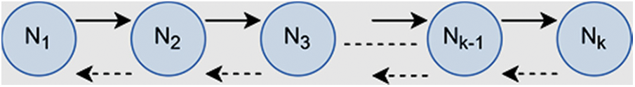
Figure 1: Hop-to-hop bidirectional communication
The proposed work analyzes the behavior and limitations of hop-to-hop communication and adopted a single server with a memoryless queuing model, M/M/1, with Poisson arrival and service pattern considered for transmitting and receiving packets from nodes within the communication range. Another way of communication in the proposed work is using the MWR node, and as depicted in Fig. 2.
In general, the MWR node is connected with the k-number of neighbor nodes. In Fig. 2, four neighbor nodes are considered, where each has a buffer to contain various generated packets that are to be transmitted to the destination. The relay node has a physical buffer, and it maintains a virtual queue to keep packet information about neighbor nodes. Each neighbor node will have bidirectional communication with relay node r. This particular information will be helpful in broadcasting encoded packets to its neighbors. In this entire scenario, the proposed queuing mechanism produces analytical results, which are quite helpful in improving the throughput, lower end-to-end delay, and latency, which are highly essential for NGNs. Following are the assumptions considered in the proposed work:
• The positions of sensor nodes are kept fixed and deployed the nodes randomly or using any artificial intelligence (AI) deployment, such as particle swarm optimization (PSO) algorithm.
• Sensor Nodes are considered homogenous; the battery is limited and is not rechargeable.
• Sink nodes are deployed to collect the sensed information from sensors.
• Sink nodes may be kept either mobile or fixed in the sensor region.
• Fixed sensors are divided into clusters for meaningful information gathering, and each cluster selects a CH.
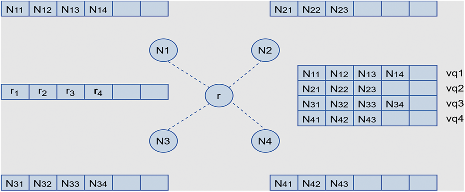
Figure 2: Relay node connected with its four neighbor nodes along with queues and virtual queues
4 Queuing Models for MHWSNs with Multiple Sinks at Network Layer
In this section, a queuing model for both hop-to-hop and MWR node communication is proposed for the WSNs. Various basic terms and assumptions are shown in the following Subsections:
4.1 The Proposed Queuing Model for Hop-to-Hop Communication
In the upcoming wireless networks, service integration plays a predominant role in controlling the packets, redirecting these packets to a destination within a stipulated time limit, and reducing the latency to meet the requirement of NGNs. The proposed queuing model applies to the network layer of the existing protocol architecture of the sensor model. Each sensor node or CH maintains a buffer to store the packets arriving from its neighbors.
Packet arrival and services: the packet arrival follows the Poisson method with a fixed rate of λ per hour, and the service rate is µ per hour. If λ/µ < 1, means the service guarantee will be fulfilled in the system is required. If λ/µ > 1 means the arrival rate is more than the service rate. Hence, at a particular time, some packets will never be served by the system. Queue length: the length of the queue is finite or infinite, but practically, the infinite is not possible due to storage limitations. In the proposed system, the sink or CH maintains a finite length queue to store and process the packets received from various nodes to enhance the sensor network’s capacity. Population: the number of packet arrivals in a fixed time interval is called population. Usually, packet arrivals from sensor nodes can be assumed as infinite in a real-time situation. In a practical situation, only a limited packets can be stored at every sensor node in WSNs. Once the buffer is complete, the remaining packets are dropped or waiting for the change in the state of the sensor node.
Queuing parameters: here, the multi-hop relay node is assumed as a single server with an infinite population. In the given scenario, sensor nodes can generate the sensed data and send it to a single server in a Poisson manner with λ arrival rate and µ service rate. The queuing parameters Ls, Lq, Ws, and Wq, are interrelated. One equation is dependent on the other parameter, and then the relationship can be decided between different settings. Let P0, P1, P2, P3, . . ., Pn are the probabilities for 0,1,2,3 . . ., n packets are in the queue, respectively. The probability of one arrival in a small interval
Pn(t+h) = Pn−1 (t)* single packet arrival and zero packet service probability + Pn+1(t)* zero packet arrival and single packet service + Pn(t) * zero packet arrival and zero packet service. As per assumption, at least one event in a small interval. The above equation is written as follows based on arrival and service rate:
By analyzing the study, the left-hand side of Eq. (2) will become zero and it will be converted as:
By substituting n = 0 in Eq. (1), it will become as:
In Eq. (4), no service probability is one because of no packets, so, the probability will become 1. Hence, after simplifying Eq. (4) and ignoring higher-order terms, the following equations are found:
In the case of steady-state, the left side of Eq. (7) is zero, therefore it is converted as:
Hence, by using Eqs. (3) and (8), the relationship between Ls, Lq, Ws and Wq can be derived as below:
Now, by substituting n = 1 in Eq. (3), it becomes:
Then we substitute Eq. (8) in the above Eq. (10), then we get:
Now, we assume that
Now, it is renowned that the sum of probabilities related to steady-state is one as:
P0 + ρ * P0 +
By knowing ρ, we can find P0, P1, P2, …. Pn, and by using these parameters, we can find Ls, Lq, Ws, and Wq in terms of ρ for M/M/1: ∞/∞ queuing model. Ls is the probable number of packets in the network shown in Eq. (12):
where j is the count of packets and
Finally, after solving it
Further, Ls = Lq + expected number of packets are going to be sent. Hence,
Eqs. (14) and (15) are well known Little’s Eq. (10) and can be applied for any kind of network or multi-hop networks to find the length of system and queue depending on arrival and service rate for improving network lifetime by optimizing the resources available at any instance. The set of equations derived from Eqs. (1)–(15) is to develop a queuing model that can estimate the packet arrival and service rate and decide the size of buffer at the sensor node or CH for hop-to-hop communication.
The processes can leave the state
As the sum of steady-state probability is 1, i.e.,
The above two Eqs. (16) and (17) state that there is an
We denote service rate
For n = c, c+1, c+2, …………
Thus,
From Eqs. (19) and (20) we can conclude as follows:
In steady-state, the probability is given by Eqs. (20) and (21) with P0 is provided in Eq. (22).
In the proposed system model, the single server queuing model is adopted to transmit and receive packets with fixed arrival and service rate at each hop-to-hop communication. The sink node or base station (BS) node is an MWR node. The hop-by-hop communication has already been explained in Section 3, wherein; it may be assumed that nodes cannot move. Further, a node can receive and transmit both simultaneously, and the supported feedback channel is reliable. In the WSNs, each sensor node communicates to another sensor node in a hop-by-hop manner by maintaining a single queue with M/M/1 queuing model [21–25] (Section 3). The mobile sink and base node act as MWR nodes. It deals with c number of parallel channels. The following section elaborates on the multi-server concept of M/M/c, where c numbers of parallel servers communicate with a multiway relay node with the mobile sink or base station (Section 4). This section will provide an analytical model to forward the packets in a hop-by-hop fashion and relay node concept with and without network coding by assuming bi-directional flow from each neighbor to the relay node revealed in Figs. 3 and 4.
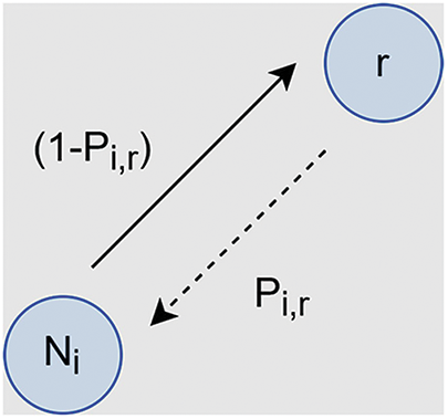
Figure 3: Hop-to-Hop Bi-directional Communication
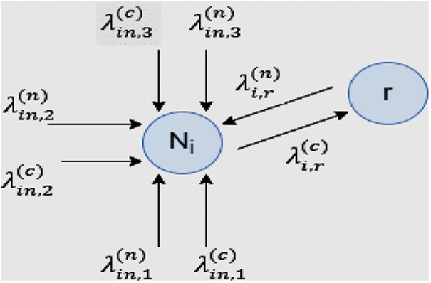
Figure 4: Relay Node is connected to k number of Neighbors ith is Ni
5.1 Non-Coding Scheme for MWR Node
This section illustrates a non-coding scheme in which, firstly, an analytical framework is provided for forwarding the packets in MWR communication. In the non-coding scheme, any intermediate node will act as an MWR node and forward the packets to neighbor nodes. For example, one of the neighbor nodes
Similarly, relay node r will send the packet to neighbor node
Packet dropping probability from
Here α denotes the retransmission count from
Now, the successful probabilities related to transmission are calculated in each link in terms of collision
In the proposed communication model, we can assume that there are no packet collisions between data packets and ACK packets because the ACKs are control packets, and these are being transmitted through a reserved channel or given high priority. So, there was no collision between the data packet and the ACK packet. In the transmission model, two kinds of transmissions are considered, i.e., one is from the relay node to its neighbor
Let
The chance of effective transmission from node
The proposed work network coding module is implemented using the multi-class queueing model in which coded packets and non-coded packets are separated in a different queue. Coded packets are considered a high priority than non-coded packets. In the proposed model, the relay node is related to
In the considered example, the relay node
The node
The resultant flow from
Generally, the decoding capacity of
In Fig. 5, the MWR decoder Node
The equations of packet flow at relay node are given in Eq. (37) as:
where
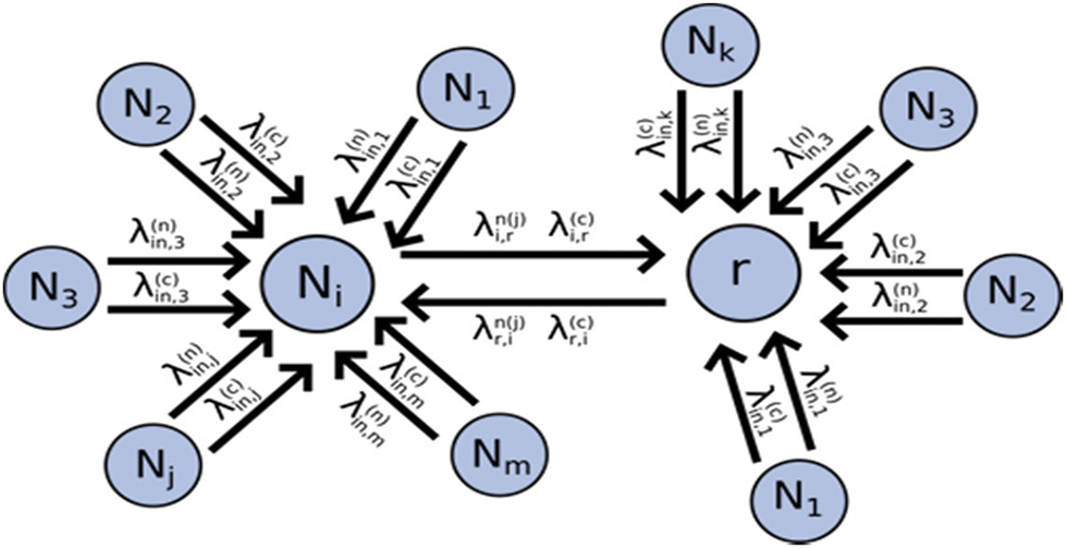
Figure 5: MWR Decoder
The packet arrival rates at queues
Total arrival at the queuing system of relay node
Assuming that the queueing system is stable and decides the output flow by using queuing principles based on its input flow. The output flows are defined as follows at the relay node based on its arrival rates:
5.5 Busy and Idle Servers in Multi-Server Model
In the proposed MWR model, the relay node generates its packets and receives packets from its neighbor nodes with a constant arrival rate. These collective packets are categorized into two classes: coded and non-coded. Afterward, these packets are forwarded to sensor nodes or sink nodes for further transmission. In the proposed model,
In addition, the relay node [25] can communicate with
The expected number of idle servers is denoted by Eq. (42).
5.6 Expected Number of Packets in the System
In the suggested system, the relay node is acting as a server and interacting with multiple servers. The expected number of packets in the system is the sum of busy servers, and packets in the queue are
By substituting
Here
Two kinds of WSNs are possible to build a network, i.e., having a static sink node or a mobile sink node. The introduced model assumes a single-server model and multi-server model with memory-less Markov chain packet with arrival and services from multiple packet flows [26]. Hop-by-hop communication is considered a single server model with chain topology, and a relay node communication, a multi-server model with virtual queues is considered for finding the network coding at the relay node. In the problem formulation, the analytical results for both the single and multi-server queuing models [27] are presented.
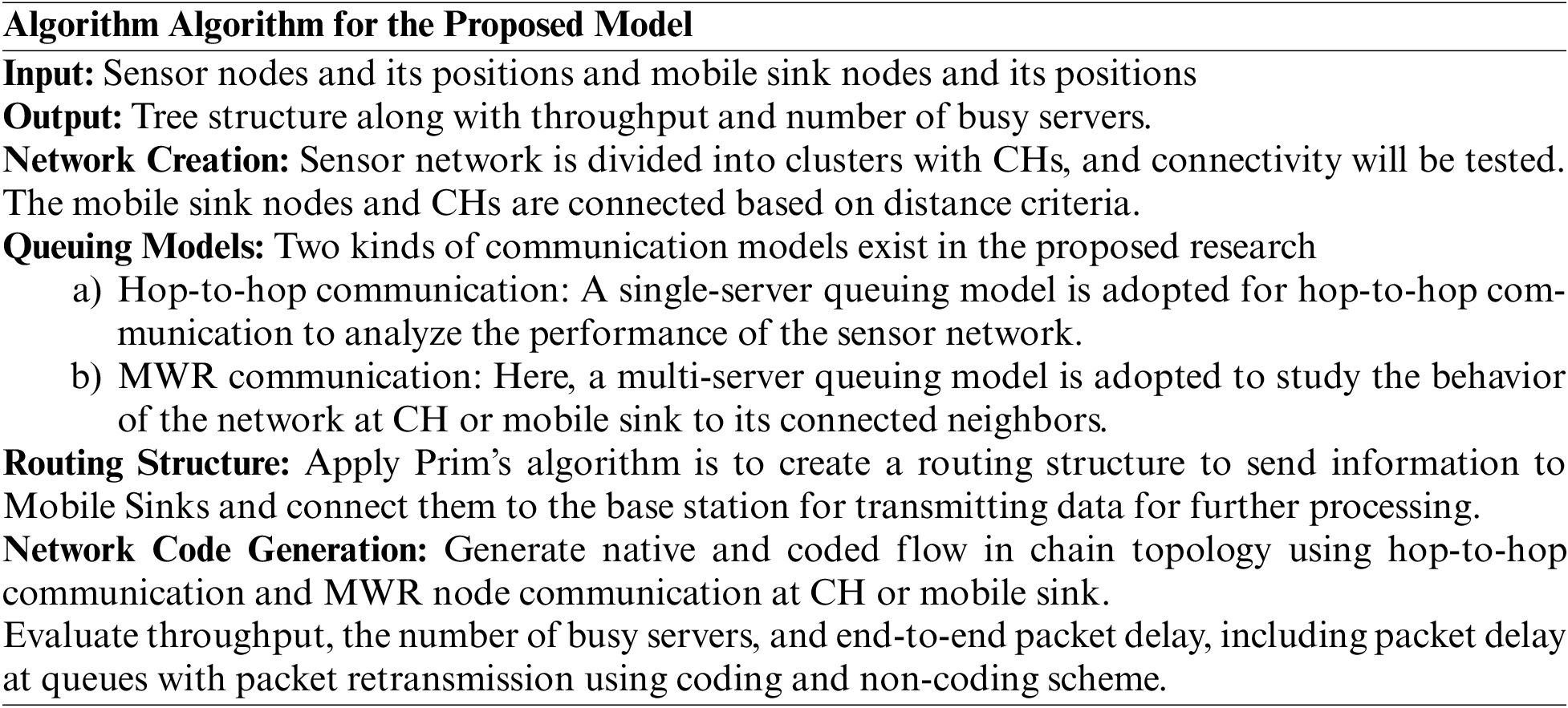
Further, queuing models are derived and can be applied in the network layer with various MAC layer protocols in MHWSNs connected with sink nodes and then to the base station. Network coding is merging packets from different flows to improve the network’s throughput. In the literature, COPE [28,29] is well-known protocol architecture that is X-OR based network coding in which an opportunistic coding concept is implemented by using a probabilistic manner. Further, different AI-based network coding techniques can also be adapted to improve the opportunistic network coding performance. The proposed analytical models are implemented using C-Language, and results are validated with analytical model and simulation outputs. The detailed implementation procedure is explained in Algorithm 1. Tab. 1 presents some parameters used in simulation:
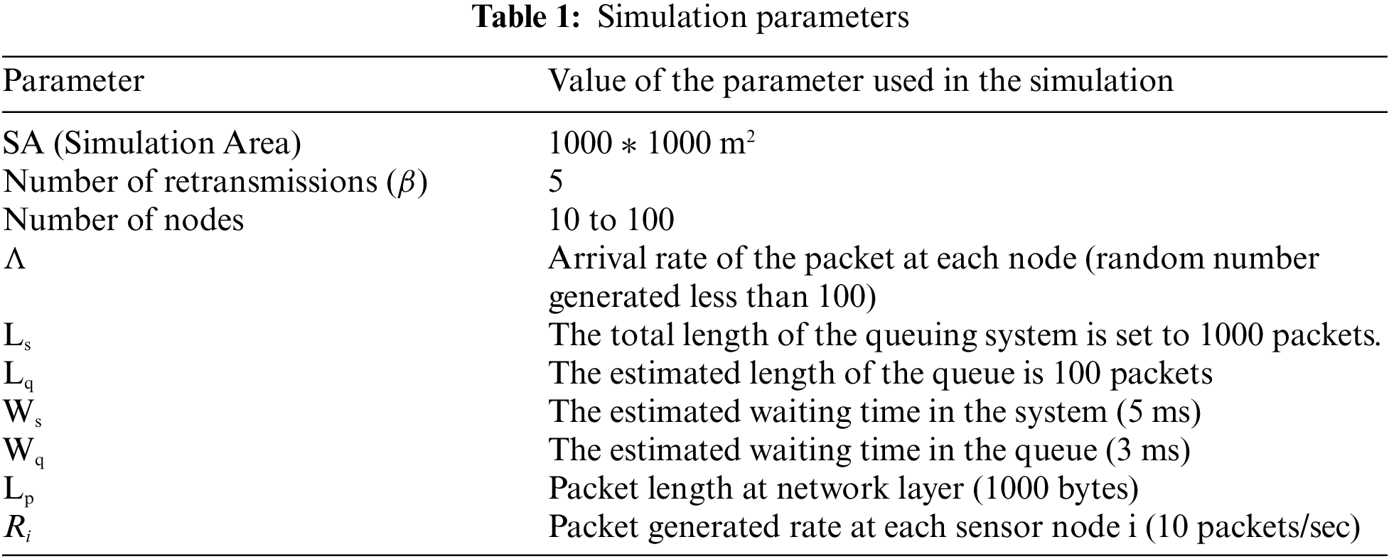
The simulation environment was created in the fixed region, i.e., 1000 * 1000 m2 area. Sensor nodes were arranged haphazardly in the sensing region. The distance between nodes was found using the Pythagorean formula. CHs are decided based on the distance between the sensor nodes to collect the information from nodes in the sensor region. Afterward, the mobile sink nodes were deployed randomly and connected to CH to collect information about the events generated in the sensor region. The proposed MWR model is implemented in the randomly generated sensor network to collect various sensor nodes. We assumed the MAC layer ideal in the implementation and network-layer protocol operations such as packet forwarding and COPE Framework to improve throughput and end-end delay. Thus, it will reduce the energy consumption in the upcoming networks while transmitting the data packets. In the practical approach, it is assumed that the number of packet retransmissions is less than 10. The maximum number of re-transmissions
6.2 Packet Generation Rate and Bit Error Rate
In the proposed model, the packet generation rate (γ), arrival rate (λ), and service rate (µ) is not fixed and vary from node to node. In this research, for different packet generation and arrival rates, the end-to-end delay and waiting time of the packet in the queue are evaluated. An unreliable channel is created by generating random packet loss for every flow depending on the distance between the nodes. An unreliable network is considered in the simulation, so the packet loss probability is based on distance, and it is not predefined.
6.3 Throughout and Number of Busy Servers
In the simulation, the packet throughput and the number of busy servers is considered analytically. The throughput is evaluated for both models, i.e., Coding Scheme and the Non-Coding scheme. Throughput is evaluated in two modes: packet retransmission and packet non-retransmission. The number of busy servers is also evaluated with and without retransmission-dependent simulation.
7 Performance Analysis of Queuing Models
In this section, Figs. 6 and 7 shows the analytical and simulation results of the proposed research with coding and non-coding schemes by considering packet retransmission value β = 5. Fig. 6a indicates the difference between the analytical and simulation model; the average throughput difference in the non-coding scheme with non-retransmission is 3.1%, whereas Fig. 6b depicts the coding scheme as 12.6%. In the coding scheme, the difference between analytical and simulation modeling is more than in the non-coding scheme. Fig. 7a shows the comparison with simulation and analysis of the non-coding scheme by considering the retransmissions is 9.4%, whereas Fig. 7b in the coding scheme is 11.8%. Here, it is also observed that in the coding scheme, the difference is more as compared to the non-Coding scheme.
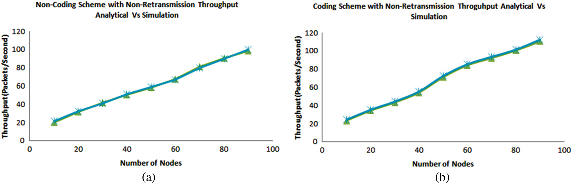
Figure 6: Non-retransmission throughput for (a) Non-coding scheme and (b) Coding scheme
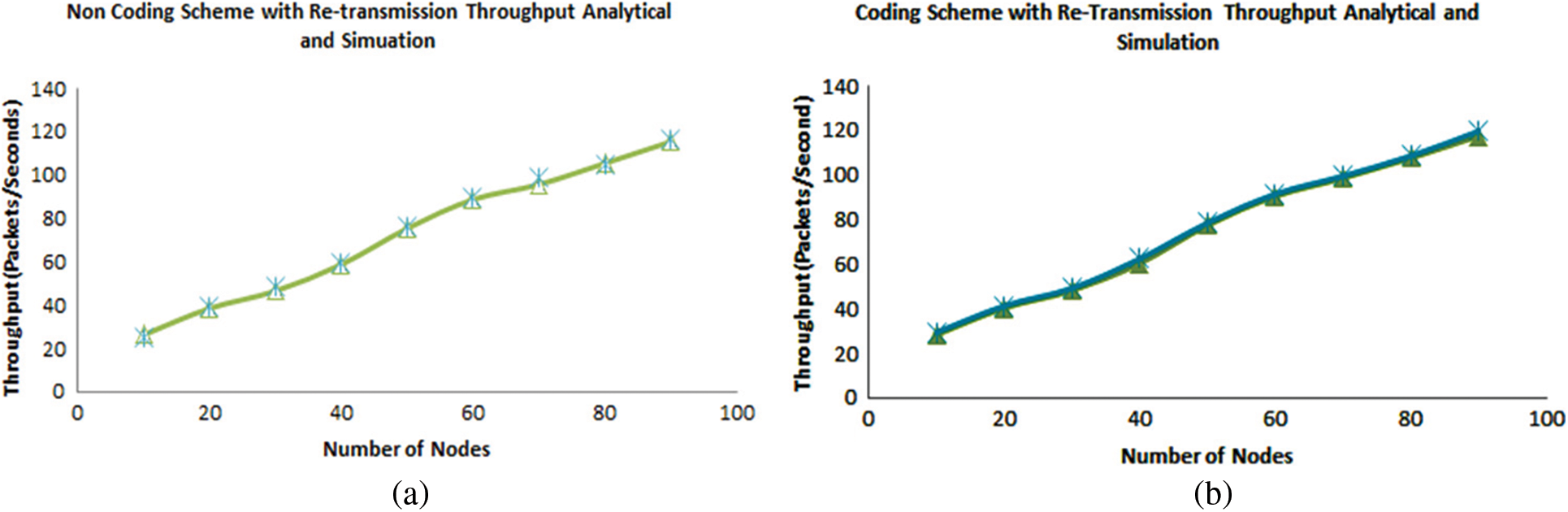
Figure 7: Retransmission throughput for (a) Non-coding scheme and (b) Coding scheme
Similarly, Fig. 8 show the difference between analytical (marked red) and simulation model busy servers in a non-coding scheme with retransmission and coding scheme with non-retransmission is 4.44% and 5.55%, respectively. The Coding scheme with non-Transmission with a busy server has a higher percentage because of the enormous number of computations to find the network coding. In Fig. 9a, the average end-to-end delay difference between analytical and simulation was found at 8.94%. While, in Fig. 9b, without retransmission shows 4.58%, which is less than with retransmission percentage. In conclusion, the end-to-end delay in retransmission mode is found more than another.
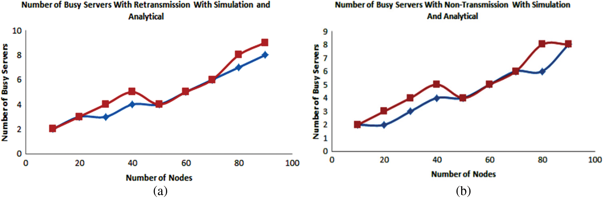
Figure 8: Number of busy servers (a) Non-coding scheme with retransmission and (b) Coding scheme with non-retransmission
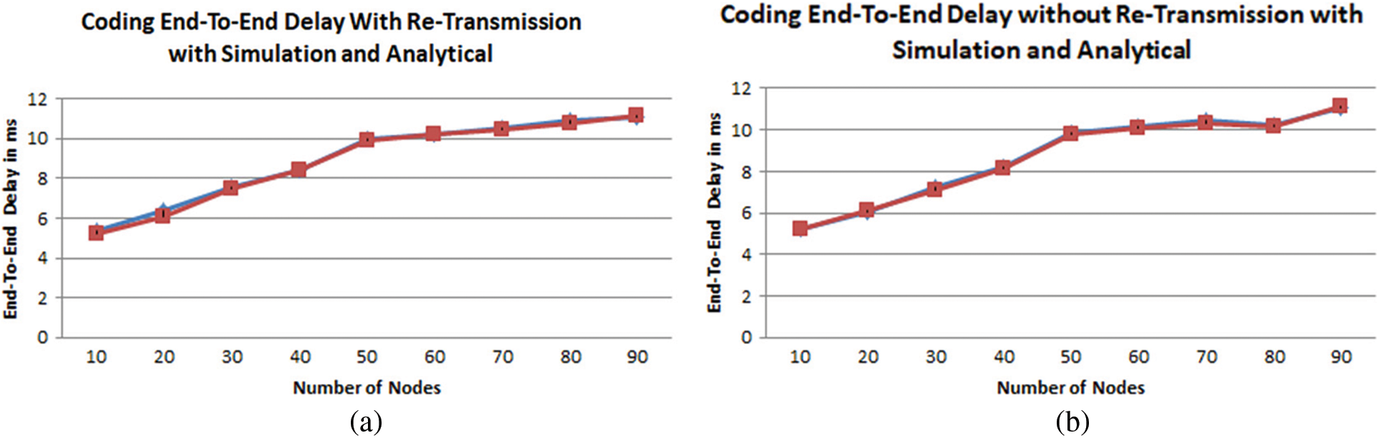
Figure 9: Coding scheme end-to-end delay (a) with retransmission and (b) without retransmission
In this paper, the queuing models were applied to implement network coding in two kinds of topologies, i.e., the chain and relay node. Further, the single-server and multi-server models are applied to estimate the buffer size at wireless nodes. The COPE protocol is implemented to forward the packets to improve the network’s capacity. By performing the simulation, the analytical results are compared with the simulation result for validation. The simulation results are found to be almost equal to analytical results. Thus, the proposed analytical framework for network coding using the MWR node is validated and found more effective. As the impact of the proposed work, various MAC layer protocols can be studied and implemented analytically, and these analytical results can be validated with simulation results.
Future Scope
In the future, the AI- based network coding may be introduced to improve the network capacity in wireless networks, and the proposed artificial network coding algorithms can be compared with traditional network coding approaches such as random linear coding codecast, and codedrip etc.
Funding Statement: This research was supported by Du Tan University, Da Nang, Vietnam.
Conflicts of Interest: The authors declare that there is no conflict of interest regarding the publication of the paper.
References
1. G. S. Paschos, C. Fragiadakis, L. Georgiadis and L. Tassiulas, “Wireless network coding with partial overhearing information,” in Proc. IEEE INFOCOM, Turin, Italy, pp. 2337–2345, 2013. [Google Scholar]
2. M. Amerimehr and F. Ashtiani, “Delay and throughput analysis of a two-way opportunistic network coding-based relay network,” IEEE Transactions on Wireless Communications, vol. 13, no. 5, pp. 2863–2873, 2014. [Google Scholar]
3. V. Jamali, N. Zlatanov and R. Schober, “Bidirectional buffer-aided relay networks with fixed rate transmission-part II: Delay constrained case,” IEEE Transactions on Wireless Communications, vol. 14, no. 3, pp. 1339–1355, 2015. [Google Scholar]
4. D. Zeng, S. Guo, Y. Xiang and H. Jin, “On the throughput of two-way relay networks using network coding,” IEEE Transactions on Parallel and Distributed Systems, vol. 25, no. 1, pp. 191–199, 2014. [Google Scholar]
5. J. Le, J. Lui and D. M. Chiu, “On the performance bounds of practical wireless network coding,” IEEE Transactions on Mobile Computing, vol. 9, no. 8, pp. 1134–1146, 2010. [Google Scholar]
6. S. Lin, L. Fu., J. Xie and X. Wang, “Hybrid network coding for unbalanced slotted aloha relay networks,” IEEE Transactions on Wireless Communications, vol. 15, no. 1, pp. 298–313, 2016. [Google Scholar]
7. A. Gupta and R. K. Jha, “A survey of 5G networks: Architecture and technologies,” IEEE Access, vol. 3, pp. 1206–1232, 2015. [Google Scholar]
8. W. Li, G. Li, S. Zhu and T. Liu, “On the performance of multiway relay communications via complex field network coding,” in Proc. Computing, Communications and IT Applications Conf., Hong Kong, China, pp. 180–185, 2013. [Google Scholar]
9. A. Singh and A. Nagaraju, “An artificial bee colony-based cope framework for wireless sensor network,” Computers, vol. 5, no. 2, pp. 1–15, 2016. [Google Scholar]
10. I. Adan and J. Resing, “Queueing systems,” Department of Mathematics and Computing Science Eindhoven University of Technology PO. Box 513, 5600 MB Eindhoven, The Netherlands, 1–28, 2015. [Google Scholar]
11. J. Le, J. C. S. Lui and D. Chiu, “On the performance bounds of practical wireless network coding,” IEEE Transaction on Mobile Computing, vol. 9, no. 8, pp. 1134–1146, 2010. [Google Scholar]
12. L. Keller, E. Atsan, K. Argyraki and C. Fragouli, “Sensecode: Network coding for reliable sensor networks,” ACM Transactions on Sensor Networks, vol. 9, no. 2, pp. 1–20, 2013. [Google Scholar]
13. M. H. Firooz, Z. Chen, S. Roy and H. Liu, “Wireless network coding via modified 802.11 MAC/PHY: Design and implementation on SDR,” IEEE Journal on Selected Areas in Communications, vol. 31, no. 8, pp. 1618–1628, 2013. [Google Scholar]
14. S. Kafaie, M. H. Ahmed, Y. Chen and O. A. Dobre, “Performance analysis of network coding with IEEE 802.11 DCF in multi-hop wireless networks,” IEEE Transactions on Mobile Computing, vol. 17, no. 5, pp. 1148–1161, 2018. [Google Scholar]
15. S. Kafaie, M. H. Ahmed, Y. Chen and O. A. Dobre, “Throughput analysis of network coding in multi-hop wireless mesh networks using queueing theory,” in Proc. IEEE Global Communications Conf. (GLOBECOM), Washington, DC, USA, pp. 1–6, 2016. [Google Scholar]
16. N. Moghadam, M. Mohebbi and H. Li, “Opportunistic scheduling for network coded data in wireless multicast networks,” in Proc. Int. Conf. on Computing, Networking and Communications (ICNC), Silicon Valley, CA, USA, pp. 996–1000, 2017. [Google Scholar]
17. J. Sharma, M. K. Jha and P. P. Bhattacharya, “Design of caucus medium access control (C-MAC) protocol for wireless sensor networks in smart grid networks,” Journal of Engineering Science and Technology, vol. 12, no. 10, pp. 2747–2765, 2017. [Google Scholar]
18. X. R. Zhang, H. L. Wu, W. Sun, A. G. Song and S. K. Jha, “A fast and accurate vascular tissue simulation model based on point primitive method,” Intelligent Automation & Soft Computing, vol. 27, no. 3, pp. 873–889, 2021. [Google Scholar]
19. X. R. Zhang, W. Z. Zhang, W. Sun, H. L. Wu, A. G. Song et al., “A real-time cutting model based on finite element and order reduction,” Computer Systems Science and Engineering, vol. 43, no. 1, pp. 1–15, 2022. [Google Scholar]
20. J. Zheng and A. Jamalipour, Wireless sensor networks: A networking perspective. Hoboken, NJ 07030, USA: John Wiley & Sons, 2009. [Google Scholar]
21. J. Medhi, Stochastic models in queueing theory, Second Edition, Florida, USA: Academic Press, Elsevier, 2003. [Google Scholar]
22. I. J. B. F. Adan, A. G. de Kok and J. A. C. Resing, “A multi-server queueing model with locking,” European Journal of Operational Research, vol. 116, pp. 16–26, 1998. [Google Scholar]
23. O. J. Boxma, “Workloads and waiting times in single-server systems with multiple customer classes,” Queueing Systems, vol. 5, pp. 185–214, 1989. [Google Scholar]
24. J. W. Cohen, The single server queue. Vol. 8. North-Holland, Amsterdam: Elsevier, 1982, ISBN: 9780444596246 [Google Scholar]
25. I. J. B. F. Adan, J. Wessels and W. H. M. Zijm, “Analysis of the symmetric shortest queue problem,” Communications in Statistics. Part C, Stochastic Models, vol. 6, pp. 691–713, 1990. [Google Scholar]
26. A. Singh and A. Nagaraju, “Energy efficient optimal path based coded transmission for multi-sink and multi-hop,” in Proc. 2nd Int. Conf. on Green Computing and Internet of Things, Bangalore, India, pp. 129–132, 2018. [Google Scholar]
27. G. Bolch, S. Greiner, H. D. Meer and K. S. Trivedi, Queueing networks and markov chains modelling and performance evaluation with computer science applications, Second Edition, John Wiley & Sons, Inc, 2006, ISBN: 978-0-471-56525-3 [Google Scholar]
28. S. Katti, H. Rahul, W. Hu, D. Katabi, M. Medard et al., “XORs in the air: Practical wireless network coding,” ACM SIGCOMM Computer Communication Review, vol. 36, no. 4, pp. 497–510, 2006. [Google Scholar]
29. A. Singh and A. Nagaraju, “Network coding: ABC based COPE in wireless sensor and mesh network,” in Proc. Int. Conf. on Contemporary Computing and Informatics (IC3I), Mysore, India, pp. 320–325, 2014. [Google Scholar]
Cite This Article
 Copyright © 2023 The Author(s). Published by Tech Science Press.
This work is licensed under a Creative Commons Attribution 4.0 International License , which permits unrestricted use, distribution, and reproduction in any medium, provided the original work is properly cited.
 Downloads
 Citation Tools