
 Submit a Paper
 Propose a Special lssue
 Open Access
ARTICLE
Characteristic of Line-of-Sight in Infrastructure-to-Vehicle Visible Light Communication Using MIMO Technique
School of Telecommunication Engineering, Suranaree University of Technology, Nakhon Ratchasima, 30000, Thailand
* Corresponding Author: Peerapong Uthansakul. Email:
Computers, Materials & Continua 2023, 74(1), 1025-1048. https://doi.org/10.32604/cmc.2023.032569
Received 22 May 2022; Accepted 28 June 2022; Issue published 22 September 2022
 View Full Text
 Download PDF
Abstract
Visible Light Communication (VLC) technology is aggressive research for the next generation of communication. Currently, Radio Frequency (RF) communication has crowed spectrum. An Intelligent Transportation System (ITS) has been improved in the communication network for Vehicle-to-Vehicle (V2 V), Vehicle-to-Infrastructure (V2I), and Infrastructure-to-Vehicle (I2 V) by using the visible light spectrum instead of the RF spectrum. This article studies the characterization of Line-of-Sight (LOS) optical performance in an Outdoor Wireless Visible Light Communication (OWVLC) system employing a Multiple-Input Multiple-Output (MIMO) technique for I2 V communications in ITS regulations. We design the new configuration of the OWVLC-I2 V system, which is an alternative approach to communication for I2 V system at nighttime. The results show the Channel Impulse Response (CIR) of the LOS links in visible light communication for I2 V system in ITS by investigating the receiver on the vehicle moving along the coverage communication area. Furthermore, the OWVLC-I2 V system using the MIMO technique depicts the performance of throughput and Bit Error Rate (BER) vs. vehicle speed while the vehicle passes a street light.Keywords
Every year, the number of deaths steadily increases, and vehicles using transportation infrastructure are also rising. A car accident is one of the leading causes of death [1]. Among death on road, accidents are often happened by the youths aged from 15 to 29 years, reported by the World Health Organization (WHO). The scientific community, the automotive industry, and government agencies collaborate to improve vehicle and road safety in this sector. There are research projects aimed at assisting people in preventing injuries and fatalities. The safety and reliability of transportation system can be significantly improved [2]. It combines Vehicle-to-Vehicle (V2 V) and Infrastructure-to-Vehicle (I2 V/V2I) communications to allow real-time data exchange between vehicles and traffic infrastructure. Since it is not influenced by broadcast storm phenomena [3,4], Visible Light Communication (VLC) technology has the potential to significantly improve vehicle network capacity, especially in high traffic congestion. The Intelligent Transportation System (ITS) [5] considers using cutting-edge collaborative technology to reduce injuries and fatalities. The ITS aims to increase transportation system performance and minimize Carbon dioxide (CO2) emissions by providing real-time access to relevant traffic information through I2 V/V2I and V2 V communications. The ITS constantly gathers analyses and distributes traffic data to improve vehicle visibility. Moreover, this knowledge aids in effectively managing transportation networks, increasing performance, and reducing traffic congestion. The transportation systems automatically use the information provided to adapt to different traffic situations. As a result, widespread adoption of ITS is crucial. On the other hand, several intelligent vehicle deployments and regional intelligence networks are required to assure system dependability and to gather and send more data effectively. Moreover, the ITS primary challenge is to keep operating costs as low as possible while ensuring reliability. The benefit of integrating transportation intelligence is efficient traffic analysis and management, which reduces traffic congestion and provides alternative routes based on traffic conditions, saving time, money, and pollution.
Existing VLC prototypes have a low error contact distance of up to 100 m in the case of camera-based systems [6–9] and 40–60 m in the case of photodiode-based systems [10–12]. As a result, the contact gap must be increased to be used in the automotive industry. The work presented in [13] has given a brief demonstration of the technological features for the most suitable I2 V/V2 V prototypes. The authors of [6] have described the nature, function, and valuation results of Optical Communication Image (OCI) sensor and demonstrated the advanced results and experimental performances of Image Sensor base Optical Wireless Communication (IS-OWC) method using the OCI. They have also shown the results of the world’s first 20 Mbps per pixel communication with 16.6 ms real-time Light-Emitting Diode (LED) detection. The VLC is not only suitable for broadcasting systems such as road communication systems or I2 V communication systems, but it is also valuable for V2 V and V2I communication systems. In V2 V cases, the vehicle in front of the traffic light receives traffic security information and transmits it to the vehicle through the brake light. They may also set up ad hoc networks for their vehicles and exchange data with the others. Similarly, a running vehicle may use its LED headlights to request data from the Roadside Unit (RSU), resulting in a full-duplex communication system [12]. The RSUs, such as LED traffic lights, are suitable for in-vehicle broadcast communications systems that work in the I2 V mode. Traffic safety information can be transmitted continuously without extra fuel, resulting in smoother traffic and fewer injuries. The light emitted by traffic lights (which make an LED array) is tuned to a frequency that the human eye cannot perceive. The modulated light is then detected by the vehicle’s receiver photodetector (PD), providing the driver with valuable safety knowledge ahead of time. A more advanced viewpoint may employ inter-vehicle communication methods to send data between vehicles stopped near traffic control poles. The work presented in [13] has provided an example explaining the use of VLC in a vehicle safety application using communication. Using intelligent traffic lights and street lighting systems, approaching vehicles can now receive road safety information (e.g., location information, traffic light mileage and time before the next change, maintenance work, and speed limit). Furthermore, vehicles can share status information (e.g., location, velocity, acceleration, and engine state). In [2], one of the most effective ways to reduce the number of collisions and associated victims is to increase vehicle awareness. Embedded sensors can sense the environment and assist drivers in dangerous situations. As mentioned, it includes ultrasound sensors used for parking aids, cameras used for traffic lanes and traffic lights, radar or lidar technology used to detect remote obstacles and measure distances. However, the sensors are limited, and in these conditions, wireless communication can provide an additional level of assistance to the driver. In [2], wireless communication allows vehicles to communicate with each other by texting and sharing information collected by sensors. By using the data collected, it can be carried out in risky situations. Nevertheless, it will not resist the driver, but it is more like a preventer of collisions. In most cases, the car’s activity ends before the driver responds. Besides safety, wireless communication improves the transportation system efficiency by providing the most suitable alternative locations and routes. The Multiple-Input Multiple-Output (MIMO) is widely used in Radio Frequency (RF) communication systems [14], where dispersion and interference generate decorrelated channels. Given a certain amount of total transmission power, MIMO channels have a greater capacity than their Single Input Single Output (SISO) counterparts. A small amount of research has been done on optical MIMO. Most optical channels use intensity modulation and direct detection. Optical MIMO is no decorrelation in most instances, and it is only in long air routes that turbulence and scattering are likely to produce as shown in [15]. The work presented in [16] has demonstrated a MIMO method to modeling an indoor system, while [17] investigated the capacity of a MIMO system and presented a low-speed demonstration. The authors of [18] have described work on space-time coding for MIMO. Preliminary experiments with a basic MIMO link have been described in [19]. There has been also a substantial body of work on the optical coupling of source and sensor arrays [20]. Several hundred Mbps up to 1 Gbps by simulation used MIMO optical wireless communication system [21]. MIMO enables the alignment needed for such a connection to be accomplished in electronic devices since light from a transmitter does not have to hit a single receiver exactly. MIMO methods may be used to understand the channel matrix, allowing the crosstalk between the channels generated by each source and detector to be quantified.
The rest of this article is organized as follows. The second topic discusses visible light communication for intelligent transportation systems. We divide the article into subheading, which are an infrastructure-to-vehicle configuration, street light illumination and power distribution, and channel modeling of the Outdoor Wireless Visible Light Communication Infrastructure-to-Vehicle (OWVLC-I2 V) using MIMO techniques. Fig. 1 shows the concept of I2V communication on the road at night. The numerical simulations of the characteristic channel impulse response are described in the Section 3. The performance of OWVLC-I2 V system using MIMO technique will be illustrated in Section 4. Finally, the conclusion is discussed in Section 5.
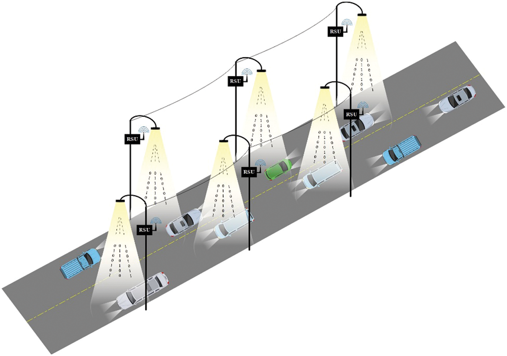
Figure 1: Concept of an infrastructure-to-vehicle communication using a VLC system
2 Visible Light Communication for Intelligent Transportation System
Annually, nearly 1.35 million people die in traffic collisions [1], and an estimated 50 million people are injured. According to experts, many accidents are triggered by the sluggish reaction and failure of car drivers to take the necessary action at the appropriate time [22]. An ITS with V2 V and I2 V connectivity ensures people protection. ITS relies on vehicles and infrastructure interacting in a truthful, robust, and secure manner (traffic lights, billboards and street lights). Since RF-based network is already overcrowded [23,24], all vehicles are outfitted with headlights and taillights that can transmit data. Traffic lights, billboards, and street lights may also broadcast important information about lanes, traffic, and weather conditions. These lighting sources can also connect users and the Internet of Everything (IoE). Cailean et al. [2] have addressed the difficulties that VLC faces in vehicular communication. The primary requirements for vehicular communications are enhanced mobility, expanded contact range, and faster data speeds. The ability of communication channels to avoid ambient or parasitic light is critical to achieving these goals. The outdoor channel is illuminated by various types of ambient lighting. VLC distance measuring and localization capabilities have been found to be helpful in vehicular communication applications. Furthermore, it is suggested that the development of disparate systems comprised of VLC and dedicated short-range communication (DSRC) or Cellular-V2X (or any other RF-based scheme) could result in a dependable system for vehicular communication because each of these technologies can compensate for the shortcomings of the others. A survey of VLC relating to 5 GHz DSRC in a hybrid preparation is produced. It is concluded that VLC systems for vehicular communication can be enhanced by researching and incorporating emerging technologies such as software-defined architecture, resource sharing, reconfigurable computing, and the introduction of new materials. Ucar et al. [25] have created a stable autonomous platoon system that is a combination of 802.11p and VLC. The autonomous platoon operates on RF-based 802.11p and is led by a platoon leader who monitors other members to precisely change the speeds. An IEEE 802.11p and VLC-based hybrid security protocol for platoon communication, namely (SP-VLC) [25] is a hybrid vehicular platoon communication protocol based on 802.11p and VLC. This protocol is intended to fix security flaws caused by the specific use of RF communication. It has been developed a simulation platform for vehicle mobility and platoon management. SP-VLC is tested in a few security flaw situations. The simulation results confirmed the findings in [13] that the RF-VLC heterogeneous system has many advantages over the RF-only system.
Emerging LED-based RSU have been used in current ITS. Kumar et al. [26] have suggested using VLC principles to broadcast information in infrastructure to vehicle (I2 V) mode. A Direct Sequence Spread Spectrum (DSSS) and Sequence Inverse Keying (SIK) are used to make noise less of an ambient light. An output metric is the sum of data obtained through a car passing by RSU. The experimental setup consists of a movable receiver and a stationary emitter separated by 1.5 m. The results show that during the day, the Packet Error Rate (PER) degrades linearly with distance, while at night, the PER differs due to the local existence of artificial light. The authors of [27] have carried out the VLC-based V2 V scheme. Uysal et al. [27] have considered a standard V2 V-VLC scenario with left and right headlamps emitting light. The Lambertian profile is used to consider the diffusion paths as well as the Line-of-Sight (LOS) path components. The results have shown that at a distance of 70 m between vehicles, a data rate of 50 Mbps can be reached depending on the position of the headlamps. The authors used VLC-based ITS for accident avoidance in [28]. VLC was used to send signals related to increasing speed, decreasing speed, and vehicle braking to ITS infrastructure (e.g., RSUs) that can cause appropriate signals. For example, in a complex setting, a vehicle can send a VLC signal to RSU, which can set a green signal or express path to minimize the number of emergency braking and lane changes. Yamazato et al. [8] have used VLC with an imaging sensor-based receiver for automotive applications. There were two scenarios I2 V and V2 V. The first scenario includes a transmitter made of LED arrays that radiates signals to roadside devices, while the receiver is a high frame rate Complementary Metal–Oxide Semiconductor (CMOS) imaging camera. In the second scenario, a special CMOS sensor capable of receiving high-speed optical signals has been produced. In the experiment, I2 V and V2 V reached data rates of 32 kb/s and 10 Mb/s, respectively. The analysis of [29] has intended a handover procedure of the V2I-VLC system, infrastructure such as street lighting could allow automatic car driving. This technique used a probabilistic algorithm based on distance to determine the handover switching time. As we all know, a car moves quickly, and each street light has a limited coverage area. The vehicle passes through a cluster of LED-powered street lights. The transition between each LED group is a major issue. The handover procedure and algorithm generated high signal quality, which was appreciated when it came time to turn to another group of LEDs. The aim of [30] was to compare RF and VLC propagation characteristics, such as radiation pattern, path loss modeling, noise and interference, and channel time variation. In other related works, [31] this research finds three contextual variables that aid real-time tiredness detection—their experimental shown that the proposed recognition approach outperforms single-fatigue feature and single-source fusion-based methods. In [32–34], Fair Power Allocation (FPA) scheme can enhance the fairness of Non-Orthogonal Multiple Access (NOMA) in VLC-based IoT networks for the intravehicular communication system. Moreover, [35–42] the I2 V communication systems were popular in traffic lights, street lights, headlights, and taillight. The transmitter used the array of White LEDs (WLEDs), and the receiver was the PD installed on the vehicle’s front hood in [36,39,40]. In contrast, others [38,41,42] placed the receiver on the top of the car, which is better for PD to receive the light. Also, in recent years there has been so much research [43–46]. The Non-LOS have been studied in [43], and the V2 V-VLC-based system model under shadowing is proposed in [44]. Furthermore, [45,46] suggested that Vehicular-Visible Light Communication (V-VLC) can improve outage performance. These deployment methodologies may be a favored solution for ITS to satisfy ultra-high reliability and ultra-low latency connectivity for Beyond 5G (B5G) vehicular networks.
2.1 Infrastructure-to-Vehicle (I2 V) Configuration
Several devices are becoming more sophisticated, and they can interact with one another. Smart street lights have been built in ITS for illumination and data communication. A White LED bulb is a lighting system critical for energy savings because LED lamps provide complete fluorescent tubes and incandescent bulb lighting. LEDs have many benefits, including a long lifetime, low power consumption, small size, cool operation, etc. As a result, future trends expect that LED lamps will be used as a substitute for traditional lamps in this course because they provide more benefits. In addition to lighting, they discovered that LEDs could be used as a data communication system. Fig. 2 illustrates a situation in which LEDs in infrastructure are used to relay traffic information to a vehicle. For ITS, the integration of both RF and VLC technologies is comfortable. White LEDs are being utilized in street lights to give the lighting on the road. Consider a street lamp to be a 5 × 5 LED array while investigating the illumination of a lighting pole street light. Each LED has a 1 W power rating and provides an illuminance of 135–320 lumens [47], a power supply voltage of 2.90–3.25 V, and a 350–700 mA current. LEDs have an irradiance angle of 120 degrees, and the color temperature offered varies from 4500 to 10000 Kelvins. The light is white color, and the temperature is 3000 Kelvins. In a commercial, the LED array is shown as a street light. The Surface Mount Device (SMD) LEDs are made up of only one LED. A single LED has a watt of power, and the LED interval is 1 cm in length.
Fig. 2 defines the geometry of the OWVLC for the I2 V communication system and the physical parameters for developing the simulation in the Matlab program. The dimension of the road is 20 m × 20 m, and the street light is installed on the top, while the height of the transmitter from the road plane is 6 m. As shown in Fig. 3, four street lamp array LEDs are placed in different positions. The receiver is placed on the vehicle dashboard. The height of the receiver from the road plane is 1.10 m. Therefore, the distance between the transmitter and the receiver (
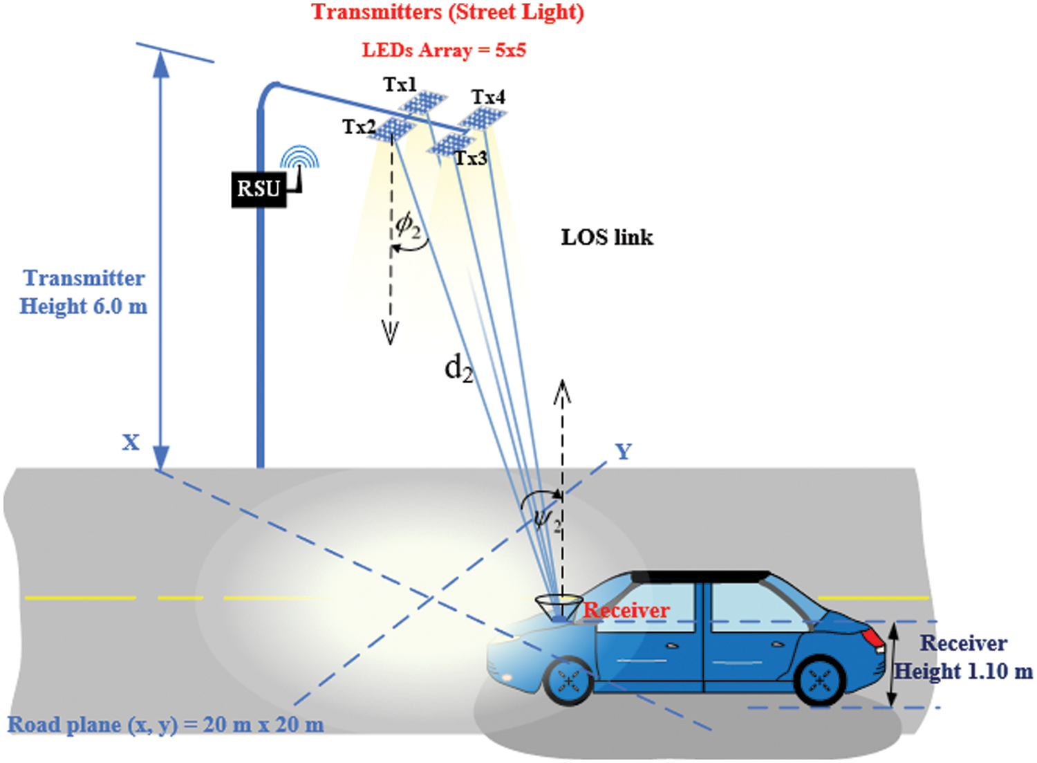
Figure 2: Geometry of the OWVLC-I2 V using MIMO technique
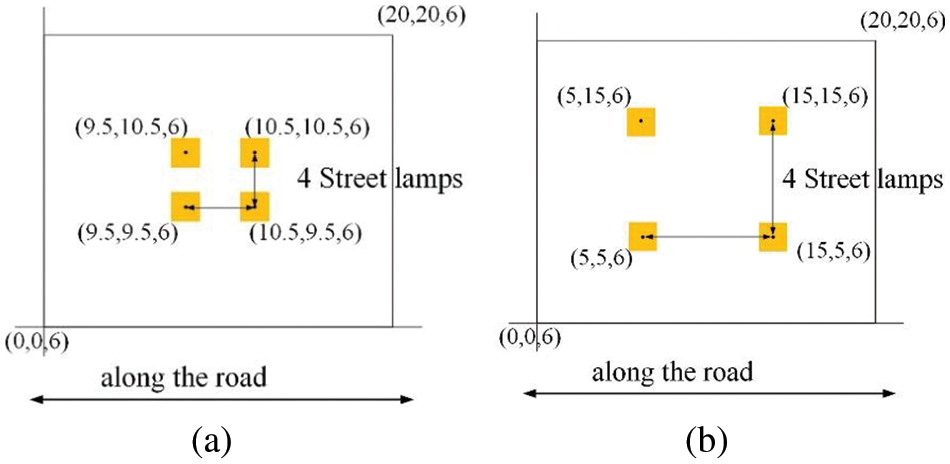
Figure 3: Street lamp transmitter position
2.2 Street Light Illumination and Power Distribution
The distribution of illuminance at a receiver plane is described in this section. It is assumed that the transmitter emits the light directly to the receiver position as the Lambertian radiation pattern [47,48]. The light intensity emitted from the transmitter, which is an array LEDs, is a cosine function dependence on the irradiance angle of emission with respect to the surface normal. The luminous intensity in angle
where
The illuminance of street light is simulated by the LED array at the position of receiver plane as the horizontal
where d is the distance between the transmitter and receiver,
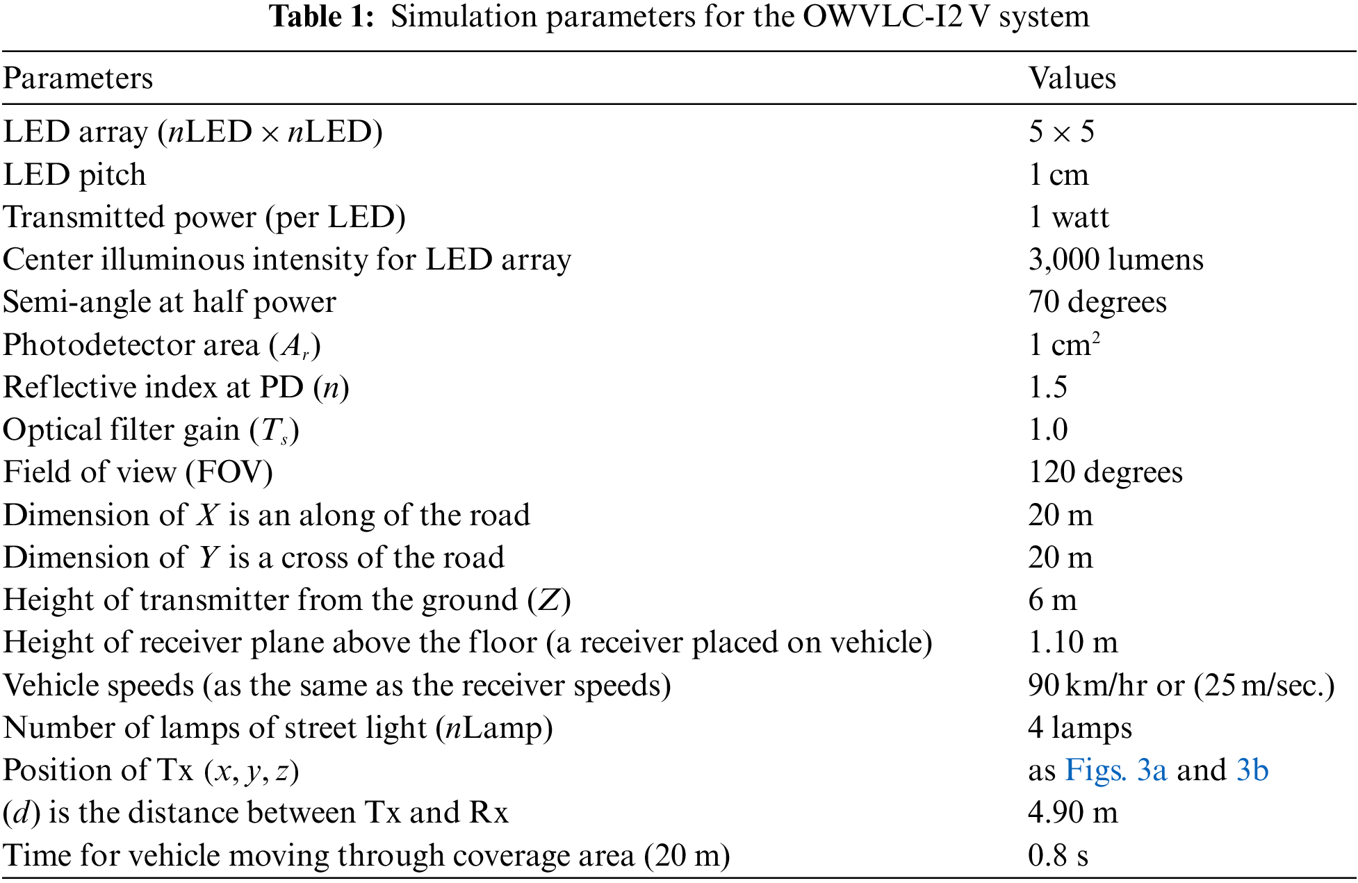
The illuminance performance of the street light is shown in Fig. 4. The simulation is carried out using Matlab program to study the illuminous intensity of the street light and as the simulation parameters in Tab. 1. For the OWVLC-I2 V system, the program calculates the direct illumination only for 1 lamp of street light by assuming that the center of luminous intensity is 3,000 lux. for 5 × 5 LEDs array. Moreover, we illustrated the illuminance by four lamps LED array. Fig. 4. shows the distribution of illuminance using one and four street lights as the transmitter with a semi-angle at half power of 70o, respectively. As Fig. 4a, the illuminous flux maximum value of 125.0 lx is right at the center and for Fig. 4b the illuminous flux maximum value of 1798.0 lx is right at the center giving an average value of 512.42 lx. The distribution of illuminance for four transmitters will receive higher illuminance if we set a semi-angle at half power of 80o, the illuminous flux maximum value of 1816.0 lx and an average value of 569.75 lx.
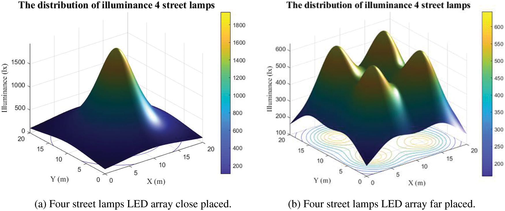
Figure 4: The distribution of illuminance street lamp by difference transmitter position
As the optical power received distribution for at receiver plane in a LOS path, the reflection path is neglected, and the power received is given by
where
where n is the refractive index when the light passed the lens at a photodetector. The concentrator gain will be zero when an incidence angle is more than FOV at the photodetector. The power received distribution performance of the street light is shown in Fig. 5, simulated by Matlab program to study the received power of the street light and as the simulation parameters shown in Tab. 1.
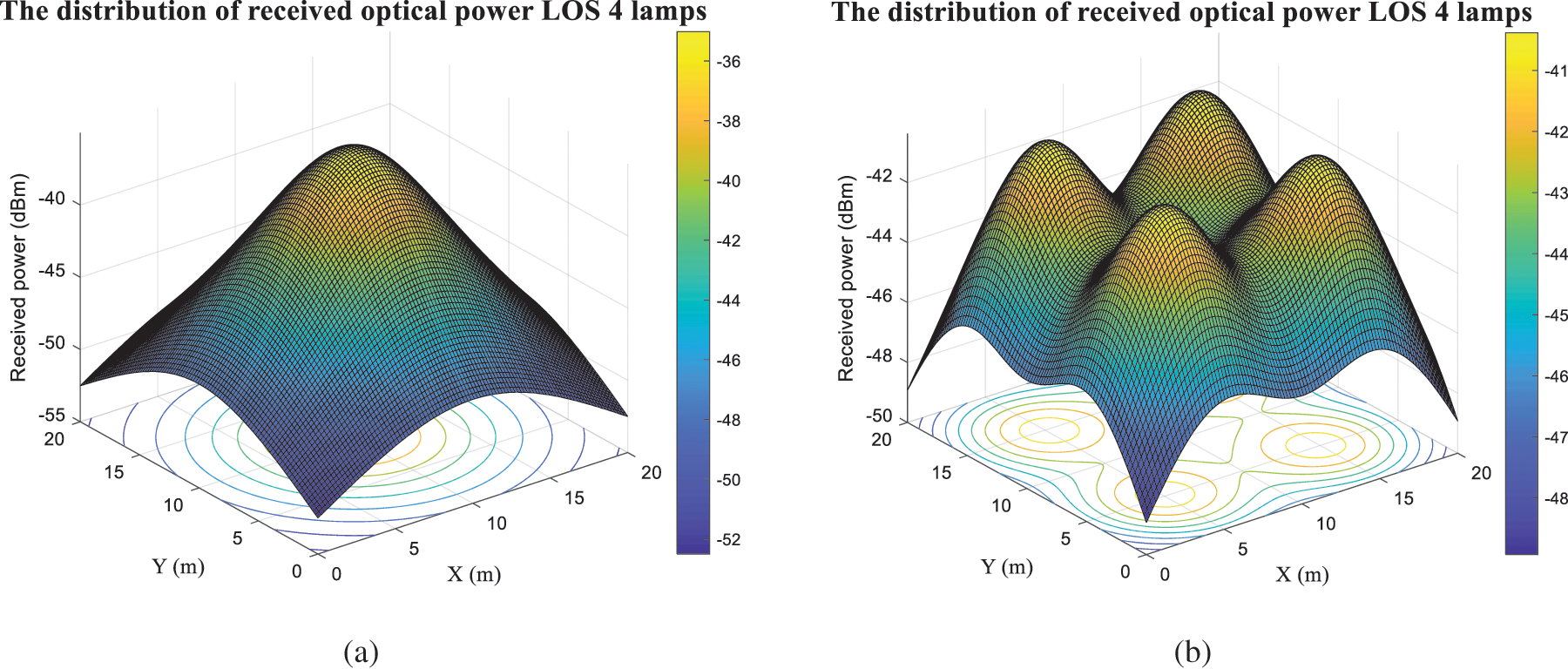
Figure 5: The distribution of received optical power LOS, (a) and (b) are transmitter at different places
According to Eq. (4), we can compute the distribution of received optical power at the LOS link of the OWVLC-I2 V system using the MIMO technique. Fig. 5 depicts the distribution of received optical power for a LOS link measured in dBm, as shown in Figs. 5a and 5b, where four street lights are placed as shown in Figs. 3a and 3b, respectively. The optical power maximum values for Figs. 5a and 5b are −35.01 dBm and −40.38 dBm. Fig. 5 shows another plot with the same value as in Figs. 5a and 5b. It is seen that the distribution of received power of Fig. 5a uncovers the edge of the road dimension, but Fig. 5b can greatly cover with the same four lamps of Fig. 5a because of the transmitter placement. Another plot with the same value as shown in Figs. 5a and 5b. It is seen that the distribution of received power in Fig. 6a does not cover the edge of the road dimension, but Fig. 6b can greatly cover with the same four lamps of Fig. 6a because of the transmitter placement.
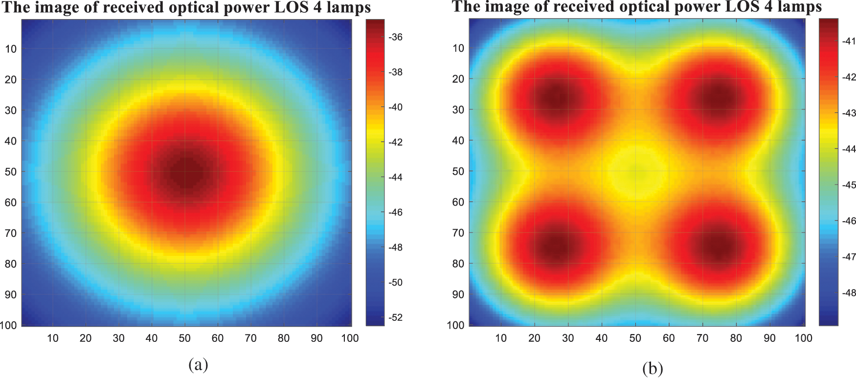
Figure 6: The image of received optical power LOS, (a) and (b) are transmitter at different places
2.3 Channel Modelling of the OWVLC-I2 V Using MIMO Technique
The distribution of the radiation intensity pattern is modeled using a generalized Lambertian radiant intensity as Eq. (1) [47,49]. The luminous intensity is used for expressing the brightness of an array LEDs. The transmitted optical power indicates the total energy radiated from an array LEDs. Luminous intensity is given in [26], that is the luminous flux per solid angle. From the topic (2.2), the transmitted power is
Consider the channel DC gain on direct paths (LOS paths), which is given by
where
where
Many MIMO systems are employed with the VLC system [21]. The optical signal is arrived at the receiver from a multiple directions of LOS links. For MIMO optical wireless channel, the LOS impulse response
where
This section describes the channel model for the OWVLC-I2 V system using multiple input single output (MISO). This configuration is to study the channel impulse response when added more transmitters and placed the receiver at the edge of the communication area. We added the transmitters with 4 lamps. Transmitters are placed at
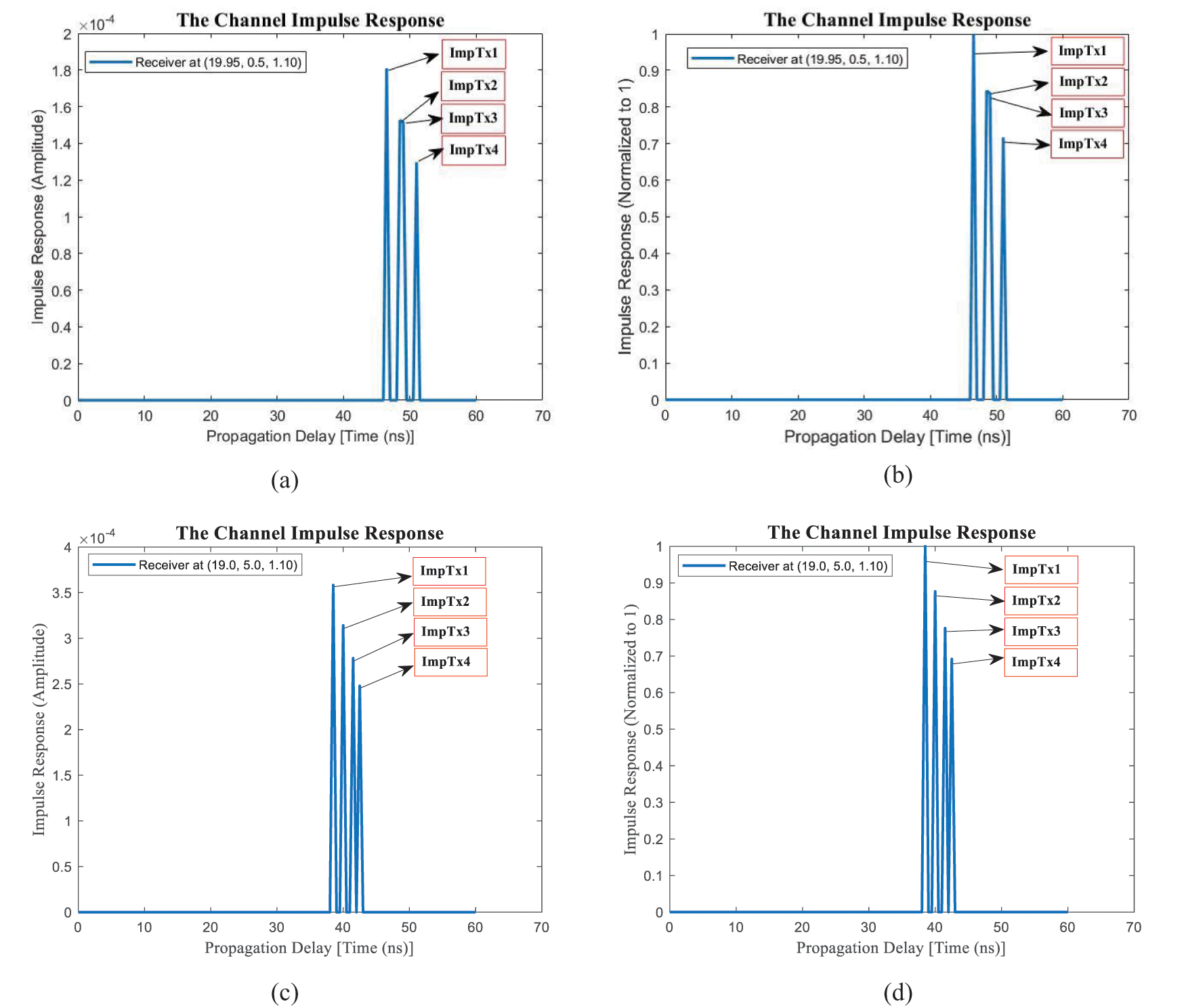
Figure 7: The channel impulse response of the OWVLC-I2 V system using MISO, (a) receiver position 1 at (19.95, 0.5, 1.10), (b) normalized to 1, (c) receiver position 2 at (19.0, 5.0, 1.10), (d) normalized to 1
3 Numerical Simulations of the Channel Impulse Response of the OWVLC-I2 V System Using MIMO Technique
The channel DC gain on the direct paths as Eq. (9), we applied to the OWVLC-I2 V system configuration by using MIMO technique. The LOS link is occurred by the number of LOS path position that can be written as infinite sum of each the LOS link positions.
where
where
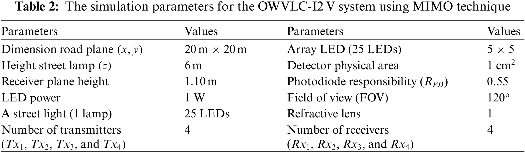
Fig. 8 shows the configuration of the OWVLC-I2 V system using MIMO technique to study the characteristic of channel impulse response of the light propagation. The receiver position is defined as Tab. 3.
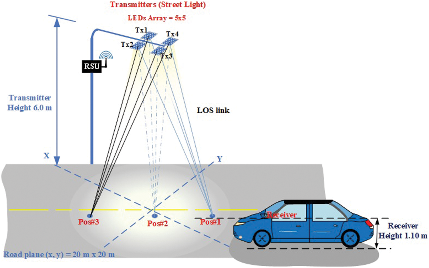
Figure 8: The light propagation of OWVLC-I2 V system using MIMO technique for LOS 3 links
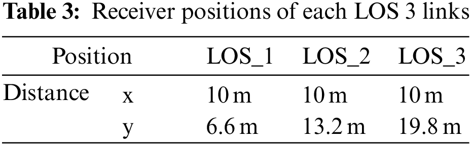
Fig. 9 shows the channel impulse response of the OWVLC-I2 V using MIMO technique which considers the number LOS of 3 positions while the receiver is on the move. The CIR signal is normalized to 1.
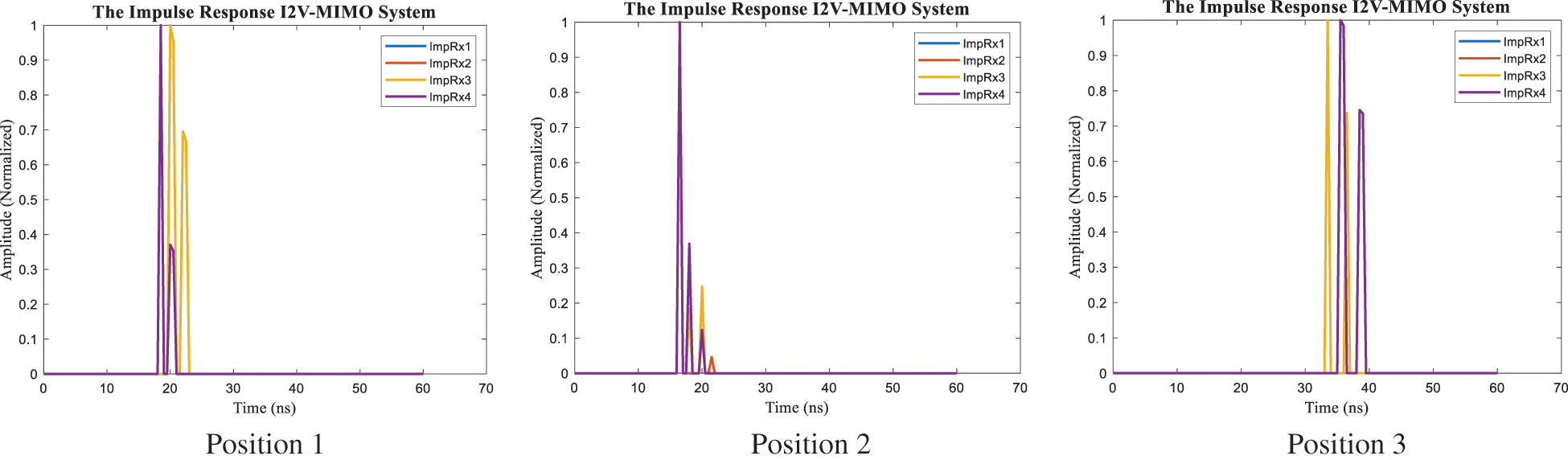
Figure 9: The simulation result for CIR of the OWVLC-I2 V system using MIMO technique with LOS 3 links
Fig. 10 illustrates the five LOS links for the OWVLC-I2 V system using MIMO technique. This is the modelling configuration to investigate the channel impulse response. The receiver position for five LOS links are shown in Tab. 4.
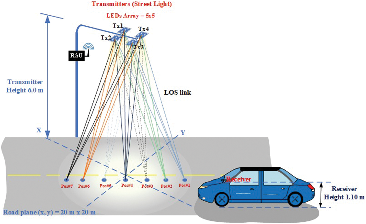
Figure 10: The light propagation of the OWVLC-I2 V system using MIMO technique for LOS 5 links
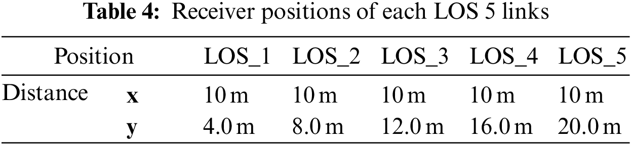
Fig. 12 illustrates the seven line-of-sight links for the OWVLC-I2 V system using MIMO technique. This is the modelling configuration to investigate the channel impulse response. The receiver position for seven LOS links are shown in Tab. 5. For example, the LOS_1 receiver center position are placed as x = 10 m and y = 2.85 m. The receivers are 4 array photodetectors.
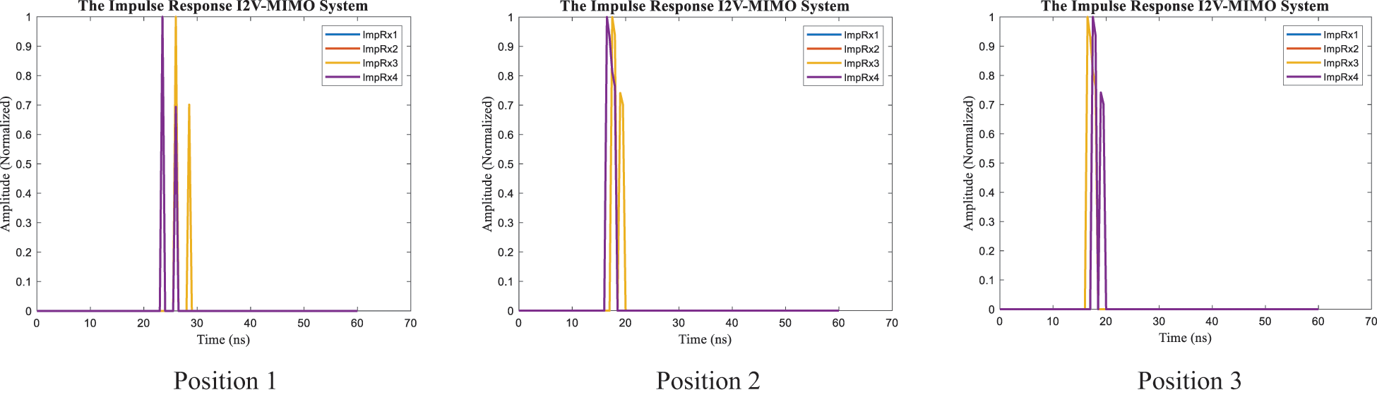
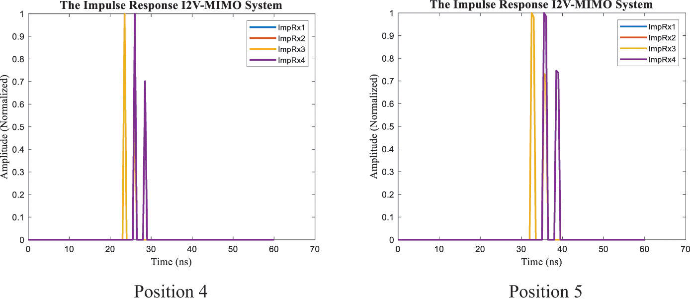
Figure 11: The simulation result for channel impulse response (CIR) of the OWVLC-I2 V using MIMO system LOS 5 links
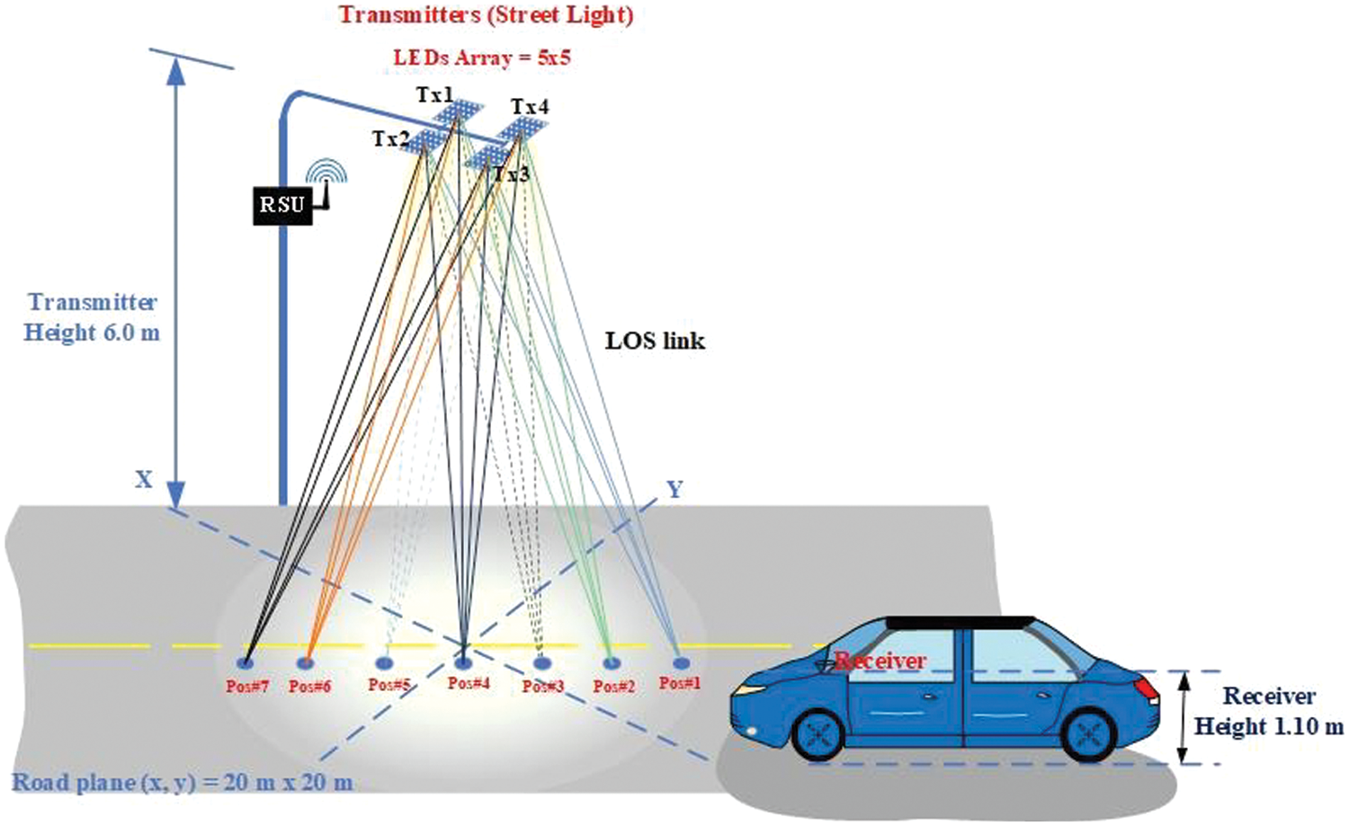
Figure 12: The light propagation of the OWVLC-I2 V system using MIMO technique for LOS 7 links
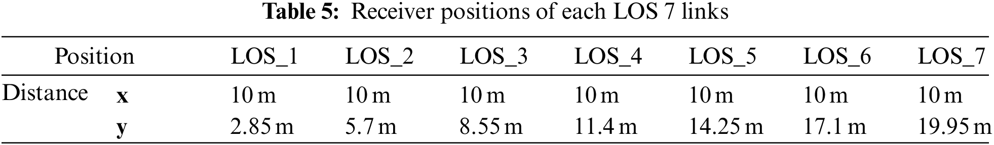
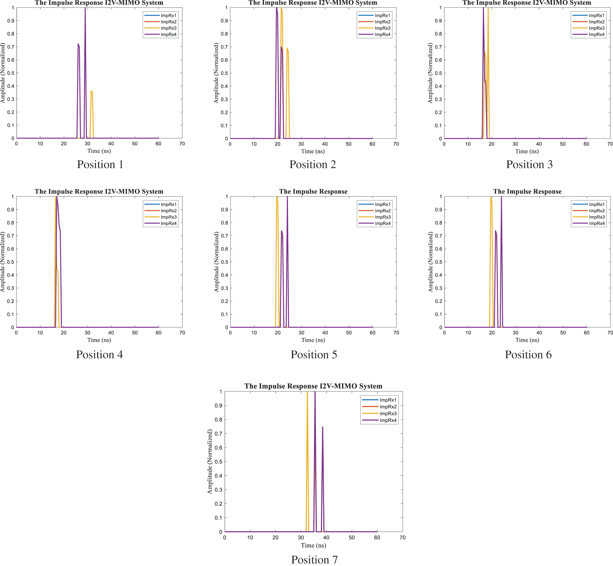
Figure 13: The simulation result for channel impulse response (CIR) of the OWVLC-I2 V using MIMO system LOS 7 links
3.4 Characteristic of Channel Impulse Response with the Different Data Rate
This section is the characteristic of channel impulse response of the OWVLC-I2 V system using MIMO technique by varying the data rate of 10 Mbps. The result shows the impulse response signal of light propagation from four transmitters to four receivers. As shown in Figs. 14a and 14c, the impulse response of along the cover communication area is overlapped by the light signal from
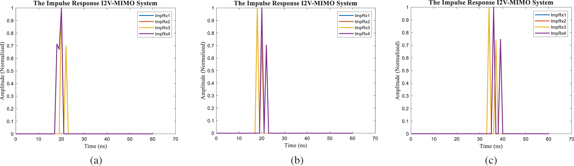
Figure 14: The simulation result for channel impulse response of the OWVLC-I2 V using MIMO system LOS 3 links
Figs. 14–16 show the CIR of the OWVLC-I2 V using MIMO technique as LOS 3, LOS 5 and LOS 7 links. We can compare with Figs. 9, 11, and Fig. 13 for each LOS 3, LOS 5 links and LOS 7 links positions respectively. The CIR with different data rate had important rise time and fall time for data rate of 10 Mbps and 20 Mbps.
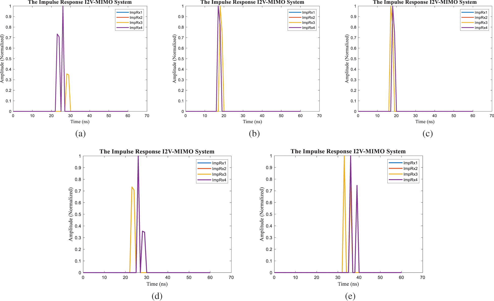
Figure 15: The simulation result for channel impulse response (CIR) of the OWVLC-I2 V using MIMO system LOS 5 links
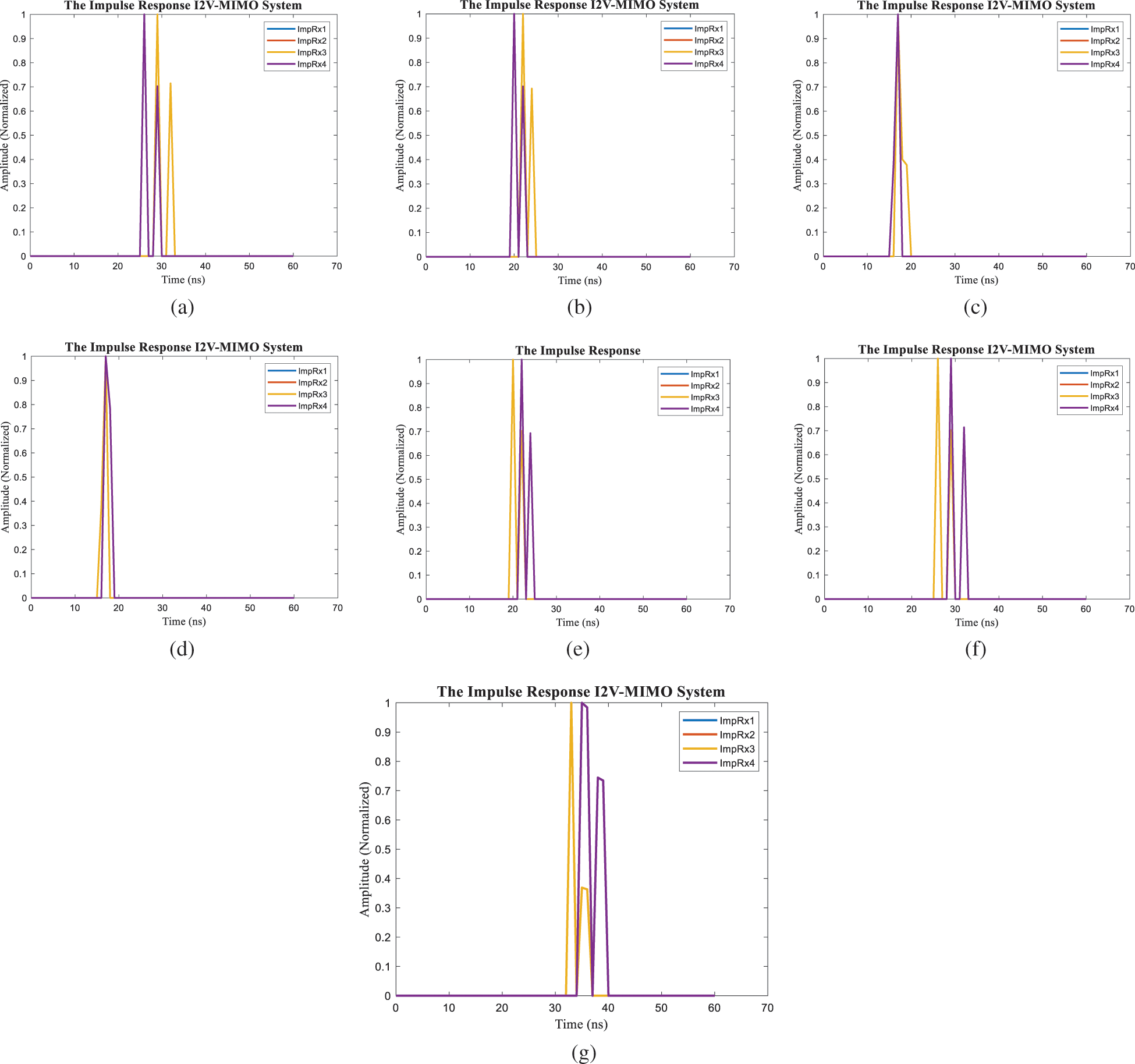
Figure 16: The simulation result for channel impulse response (CIR) of the OWVLC-I2 V MIMO system LOS 7 links
The light is converted to the electrical current as
where the shot noise and amplifier noise variances are given by [50]
where
The bit error rate can be calculated from the SNR as
4 The Performance of the OWVLC-I2 V System Using MIMO Technique
In this section, we perform the data transmission for the OWVLC-I2 V system using MIMO technique. The data input is a serial of
The measurement performance of the OWVLC-I2 V system is illustrated in the Bit Error Rate (BER). The BER performance at a data rate is 20 Mbps. Fig. 17 shows the BER of the OWVLC-I2 V system using the MIMO technique with LOS 3 links, which is related to the CIR of Fig. 9 that we have designed to investigate the CIR of the OWVLC-I2 V system when the vehicle moves through the communication area. We divided the communication links into 3, 5, and 7 links to study the performance of each link and which one is better for the I2 V system. It will represent the I2 V communication system during the vehicle movement through the street light.
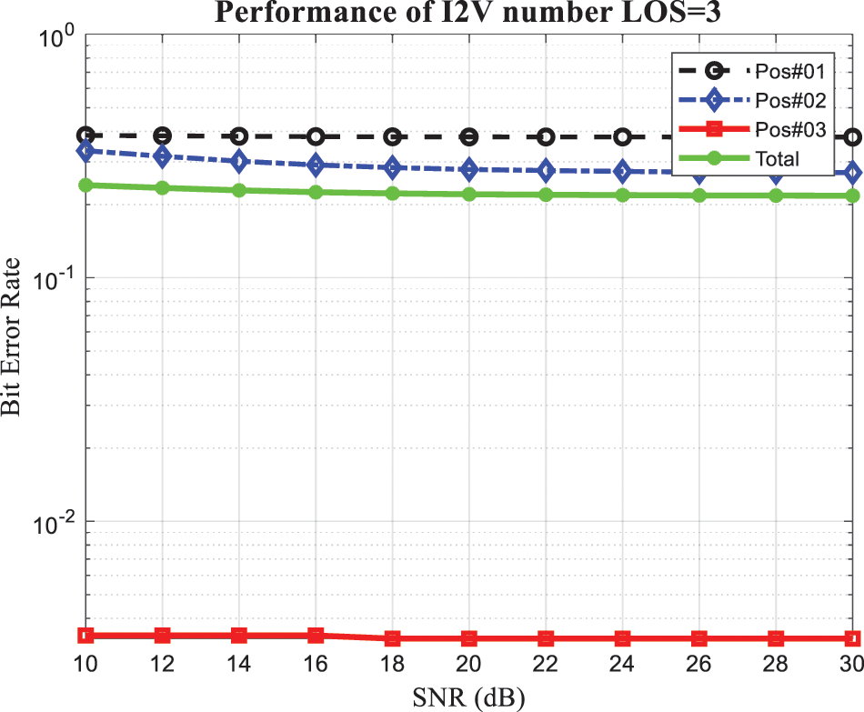
Figure 17: Bit error rate of the OWVLC-I2 V system using MIMO technique with LOS 3 links
Fig. 18 shows the BER performance of the OWVLC-I2 V system that used the characteristics of the LOS 5 and 7 links as Figs. 18a and 18b, respectively, at the data rate of 20 Mbps. It can be seen that the BER performance for all LOS links, the LOS 3 links looked better than the LOS 5 and 7 links. Therefore, BER was too high from our study for all the LOS 3, 5, and 7 links in terms of Inter-Symbol Interference (ISI) of the received signal. One is the simple receiver design for signal processing. The satisfied LOS links to represent the OWVLC-I2 V system is LOS 3 links that we decided from the BER performance.
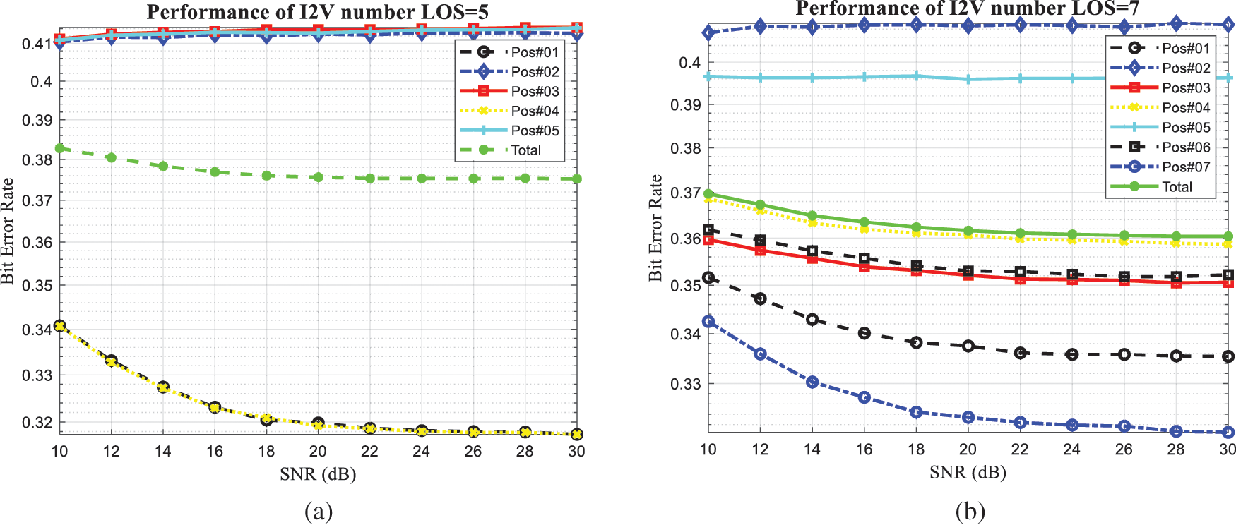
Figure 18: Bit error rate of the OWVLC-I2 V system using MIMO technique (a) with LOS 5 links, and (b) with LOS 7 links
Fig. 19 shows the performance of the vehicle speed versus the data throughput of the OWVLC-I2 V system using the MIMO technique while the vehicle passes a street light. We compared two data rates, 10 Mbps and 20 Mbps, according to the characteristics of LOS links of both data rates. There is a significant difference in throughput at a low vehicle speed of 20 km/hr. Furthermore, there is a slight difference in high vehicle speed of 140 km/hr.
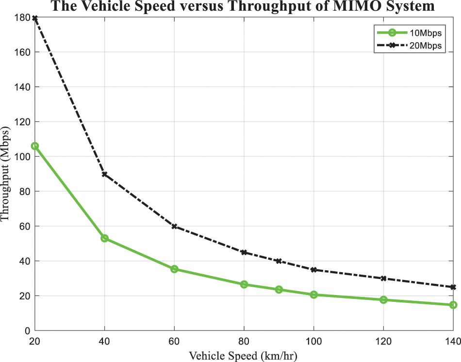
Figure 19: Data throughput of the OWVLC-I2 V system using MIMO technique
ITS is used by information and communication technologies for managing transportation and traffic to improve the efficiency of the road system, public transportation systems, and traffic safety to reduce accidents and congestion in the traffic. The advantages of ITS are that the warning signs appear before the drivers arrive at the accident point, allowing them to avoid the accident, and the limited speed signs, which can change the speeds before they arrive at regulated areas. Due to the presence of vehicle lights and the existing traffic light infrastructure, VLC could be used for vehicular communication. Outdoor wireless visible light communication is applied for infrastructure to vehicles in ITS. We investigated the channel impulse response of the MISO system for the I2 V communication system. The system analysis in this paper represents the channel impulse response of MISO and MIMO techniques while the receiver is on the move, and it may be that some perform the relation between vehicle speed and received data. It is worthy of further work to improve the data rate even more than our current configuration system. The BER performance of the OWVLC-I2 V system using the MIMO technique needs to be improved further in the following work. The performance BER of the OWVLC-I2 V system unachieved the BER of 10–4. Therefore, there are many challenges to improve the OWVLC-I2 V system, such as robust noise effects, distance communication, coverage area, and daytime communication, which will be considered for study in the next future.
Acknowledgement: The authors would like to thank the Ministry of Higher Education, Science and Research Innovation of Thailand for supporting the scholarship to study Ph.D. and thanks the Nakhon Pathom Rajabhat University for supporting the full-time study.
Funding Statement: This work was supported in part by the Ministry of Higher Education, Science and Research Innovation of Thailand.
Conflicts of Interest: The authors declare that they have no conflicts of interest to report regarding the present study.
References
1. World Health Organization (WHO) “Global status report on road safety 2018,” [Online]. Available: https://www.who.int/violence_injury_prevention/road_safety_status/2018/en/. [Google Scholar]
2. A. -M. Cailean, B. Cagneau, L. Chassagne, V. Popa and M. Dimian, “A survey on the usage of DSRC and VLC in communication-based vehicle safety applications,” in IEEE 21st Symp. on Communications and Vehicular Technology in the Benelux (SCVT), Delft, The Netherlands, pp. 69–74, Nov. 2014. [Google Scholar]
3. O. K. Tonguz, N. Wisitpongphan, J. S. Parikh, F. Bai, P. Mudalige et al., “On the broadcast storm problem in ad hoc wireless networks,” in 3rd Int. Conf. on Broadband Communications, Networks and Systems, San Jose, CA, USA, Oct. 2006, pp. 1–11, 2016. [Google Scholar]
4. N. Wisitpongphan, O. K. Tonguz, J. S. Parikh, P. Mudalige, F. Bai et al., “Broadcast storm mitigation techniques in vehicular ad hoc networks,” IEEE Wireless Communications, vol. 14, no. 6, pp. 84–94, 2007. [Google Scholar]
5. P. Papadimitratos, A. De La Fortelle, K. Evenssen, R. Brignolo and S. Cosenza, “Vehicular communication systems: Enabling technologies, applications, and future outlook on intelligent transportation,” IEEE Communications Magazine, vol. 47, no. 11, pp. 84–95, 2009. [Google Scholar]
6. I. Takai, S. Ito, K. Yasutomi, K. Kagawa, M. Andoh et al., “LED and CMOS image sensor based optical wireless communication system for automotive applications,” IEEE Photonics Journal, vol. 5, no. 5, Art. no. 6801418, 2013. [Google Scholar]
7. I. Takai, T. Harada, M. Andoh, K. Yasutomi, K. Kagawa et al., “Optical vehicle-to-vehicle communication system using LED transmitter and camera receiver,” IEEE Photonics Journal, vol. 6, no. 5, Art. no. 7902513, 2014. [Google Scholar]
8. T. Yamazato, I. Takai, H. Okada, T. Fujii, T. Yendo et al., “Image-sensor-based visible light communication for automotive applications,” IEEE Communications Magazine, vol. 52, no. 7, pp. 88–97, 2014. [Google Scholar]
9. Y. Goto, I. Takai, T. Yamazato, H. Okada, T. Fujii et al., “A new automotive VLC system using optical communication image sensor,” IEEE Photonics Journal, vol. 8, no. 3, pp. 1–17, 2016. [Google Scholar]
10. S. Okada, T. Yendo, T. Yamazato, T. Fujii, M. Tanimoto et al., “On-vehicle receiver for distant visible light road-to vehicle communication,” in IEEE Intelligent Vehicles Symp. (IV), Xi’an, China, pp. 1033–1038, 14 July 2009. [Google Scholar]
11. A. -M. Cailean, B. Cagneau, L. Chassagne, M. Dimian and V. Popa, “Novel receiver sensor for visible light communications in automotive applications,” IEEE Sensors Journal, vol. 15, no. 8, pp. 4632–4639, 2015. [Google Scholar]
12. N. Lourenço, D. Terra, N. Kumar, L. N. Alves and R. L. Aguiar, “Visible light communication system for outdoor applications,” in 8th Int. Symp. on Communication Systems, Networks & Digital Signal Processing (CSNDSP), Poznañ, Poland, July 2012, pp. 1–6, 2012, July 2012. [Google Scholar]
13. A. -M. C˘ailean and M. Dimian, “Current challenges for visible light communications usage in vehicle applications: A survey,” in IEEE Communication Surveys & Tutorials, Fourth Quarter, vol. 19, no. 4, pp. 2681–2703, 2017. [Google Scholar]
14. D. Gesbert, M. Shafi, D. -S. Shiu, P. J. Smith and A. Naguib, “From theory to practice: An overview of MIMO space-time coded wireless systems,” IEEE Journal Selected Areas in Communications, vol. 21, pp. 281–302, 2003. [Google Scholar]
15. S. G. Wilson, M. Brandt-Pearce, Q. Cao and J. Leveque, “Optical MIMO transmission using Q-ary PPM for atmospheric channels,” The Thirty-Seventh Asilomar Conference on Signals, Systems & Computers, vol. 1, pp. 1090–1094, 2003. [Google Scholar]
16. S. Jivkova, B. A. Hristov and M. Kavehrad, “Power-efficient multi-spot-diffuse multiple-input-multiple-output approach to broad-band optical wireless communications,” IEEE Transaction on Vehicular Technology, vol. 53, no. 3, pp. 882–889, 2004. [Google Scholar]
17. S. Hranilovic and F. R. Kschischang, “A pixelated MIMO wireless optical communication system,” IEEE Journal of Selected Topics in Quantum Electronics, vol. 12, no. 4, pp. 859–874, 2006. [Google Scholar]
18. M. Garfield, C. Liang, P. Kurzweg and K. R. Dandekar, “MIMO Space-time coding for diffuse optical communication,” Microwave and Optical Technology Letters, vol. 48, pp. 1108–10, 2006. [Google Scholar]
19. D. O’Brien, “Indoor optical wireless communications: Recent developments and future challenges,” in Proc. SPIE 7464 Free-Space Laser Communications IX, San Diego, CA, USA, vol. 7464, pp. 74640B-12, 2009. [Google Scholar]
20. A. G. Kirk, “Free-Space Optical Interconnects,” in Optical Interconnects: The Silicon Approach, L. Pavesi and G. G. Guillot, Eds. Berlin: Springer, 2006. [Google Scholar]
21. L. Zeng, D. O’Brien, H. L. Minh, G. E. Faulkner, K. Lee et al., “High data rate multiple input multiple output (MIMO) optical wireless communications using white LED lighting,” IEEE Journal Selected Areas in Communications, vol. 27, no. 9, pp. 1654–1662, 2009. [Google Scholar]
22. M. Abualhoul, “Visible light and radio communication for cooperative autonomous driving: Applied to vehicle convoy,” Ph.D. Thesis, MINES ParisTech, Paris, France, 2016. [Google Scholar]
23. S. Arnon, “Optimised optical wireless car-to-traffic-light communication,” Transactions on Emerging Telecommunications Technologies, vol. 25, pp. 660–665, 2014. [Google Scholar]
24. X. Tang, H. Le-Minh, W. Viriyasitavat, Z. Ghassemlooy, H. M. Tsai et al., Car-to-Car Visible Light Communications. in Visible Light Communications, CRC Press: Boca Raton, FL, USA, pp. 275–304, 2017. [Google Scholar]
25. S. Ucar, S. C. Ergen and O. Ozkasap, “IEEE 802.11 p and visible light hybrid communication based secure autonomous platoon,” IEEE Transactions on Vehicular Technology, vol. 67, pp. 8667–8681, 2018. [Google Scholar]
26. N. Kumar, N. Lourenço, D. Terra, L. N. Alves and R. L. Aguiar, “Visible light communications in intelligent transportation systems,” in 2012 IEEE Intelligent Vehicles Symp., Madrid, Spain, pp. 748–753, June 2012. [Google Scholar]
27. M. Uysal, Z. Ghassemlooy, A. Bekkali, A. Kadri and H. Menouar, “Visible light communication for vehicular networking: Performance study of a V2 V system using a measured headlamp beam pattern model,” IEEE Vehicular Technology Magazine, vol. 10, pp. 45–53, 2015. [Google Scholar]
28. N. Wang, C. Liu, Y. Lu and J. Shen, “A visible light communication (VLC) based intelligent transportation system for lorry fleet,” in 2017 16th Int. Conf. on Optical Communications and Networks (ICOCN), Wuzhen, China, 7–10 August, pp. 1–3, 2017. [Google Scholar]
29. Q. -H. Dang and M. Yoo, “Handover procedure and algorithm in vehicle to infrastructure visible light communication,” IEEE Access, vol. 5, pp. 26466–26475, 2017. [Google Scholar]
30. L. Cheng, W. Viriyasitavat, M. Boban and H. M. Tsai, “Comparison of radio frequency and visible light propagation channels for vehicular communications,” IEEE Access, vol. 6, pp. 2634–2644, 2017. [Google Scholar]
31. W. Sun, G. C. Zhang, X. R. Zhang, X. Zhang and N. N. Ge, “Fine-grained vehicle type classification using lightweight convolutional neural network with feature optimization and joint learning strategy,” Multimedia Tools and Applications, vol. 80, no. 20, pp. 30803–30816, 2021. [Google Scholar]
32. W. Sun, X. Zhang, S. Peeta, X. He and Y. Li, “A Real-time fatigue driving recognition method incorporating contextual features and two fusion levels,” IEEE Transactions on Intelligent Transportation Systems, vol. 18, no. 12, pp. 3408–3420, 2017. [Google Scholar]
33. R. Raj, K. Jindal and A. Dixit, “Fairness enhancement of non-orthogonal multiple access in VLC-based IoT networks for intravehicular applications,” IEEE Transactions on Vehicular Technology, (https://doi.org/10.1109/TVT.2022.3167091), 2022. [Google Scholar]
34. X. Deng, W. Fan, T. B. Cunha, S. Ma, C. Chen et al., “Two-dimensional power allocation for optical MIMO-OFDM systems over low-pass channels,” IEEE Transactions on Vehicular Technology, (https://doi.org/10.1109/TVT.2022.3162621), 2022. [Google Scholar]
35. H. B. Eldeeb, S. M. Saiit and M. Uysal, “Visible light communication for connected vehicles: How to achieve the omnidirectional coverage?,” IEEE Access, vol. 9, pp. 103885–103905, 2021. [Google Scholar]
36. N. Kumar, D. Terra, N. Lourenco, L. N. Alves and R. L. Aguiar, “Visible light communication for intelligent transportation in road safety applications,” in Proc. 7th Int. Wireless Communication Mobile Computer Conf., Istanbul, Turkey, Jul 2011, pp. 1513–1518, 2011. [Google Scholar]
37. K. Cui, G. Chen, Z. Xu and R. D. Roberts, “Traffic light to vehicle visible light communication channel characterization,” Applied Optics, vol. 51, no. 27, pp. 6594–6605, 2012. [Google Scholar]
38. J. -H. Lee and S. -Y. Jung, “SNR analyses of the multi-spectral light channel for optical wireless LED communications in intelligent transportation system,” in Proc. IEEE 79th Vehicular Technology Conf. (VTC Spring), Seoul, Korea (Southpp. 1–5, May 2014. [Google Scholar]
39. T. Nawaz, M. Seminara, S. Caputo, L. Mucchi, F. S. Cataliotti et al., “IEEE 802.15. 7-compliant ultra-low latency relaying VLC system for safety-critical ITS,” IEEE Transaction on Vehicular Technology, vol. 68, no. 12, pp. 12040–12051, 2019. [Google Scholar]
40. M. Seminara, T. Nawaz, S. Caputo, L. Mucchi and J. Catani, “Characterization of field of view in visible light communication systems for intelligent transportation systems,” IEEE Photonics Journal, vol. 12, no. 4, pp. 1–16, Aug. 2020. [Google Scholar]
41. X. You, Y. Zhong, J. Chen and C. Yu, “Mobile channel estimation based on decision feedback in vehicle-to-infrastructure visible light communication systems,” Optics Communications, vol. 462, Art. no. 125261, 2020. [Google Scholar]
42. M. S. Demir, H. B. Eldeeb and M. Uysal, “CoMP-based dynamic handover for vehicular VLC networks,” IEEE Communications Letters, vol. 24, no. 9, pp. 2024–2028, 2020. [Google Scholar]
43. B. Turan, O. Narmanlioglu, O. N. Koc, E. Kar, S. Coleri et al., “Measurement based non-line-of-sight vehicular visible light communication channel characterization,” Electrical Engineering and Systems Science in Signal Processing, (arXiv:2111.11369[eess. SP]2021. [Google Scholar]
44. P. Sharda, M. R. Bhatnagar and Z. Ghassemlooy, “Modeling of a vehicle-to-vehicle based visible light communication system under shadowing and investigation of the diversity-multiplexing tradeoff,” IEEE Transactions on Vehicular Technology, (https://doi.org/10.1109/TVT.2022.3176907), 2022. [Google Scholar]
45. G. Singh, A. Srivastava and V. A. Bohara, “Visible light and reconfigurable intelligent surfaces for beyond 5G V2X communication networks at road intersections,” IEEE Transactions on Vehicular Technology, (https://doi.org/10.1109/TVT.2022.3174131), 2022. [Google Scholar]
46. M. Fouda, S. Hashima, S. Sakib, Z. Fadlullah, K. Hatano et al., “Optimal channel selection in hybrid RF/VLC networks: A multi-armed bandit approach,” IEEE Transactions on Vehicular Technology, vol. 71, no. 6, pp. 6853–6858, 2022. [Google Scholar]
47. T. Komine and M. Nakagawa, “Fundamental analysis for visible-light communication system using LED lights,” IEEE Transactions on Consumer Electronics, vol. 50, pp. 100–107, 2004. [Google Scholar]
48. J. M. Kahn and J. R. Barry, “Wireless infrared communications,” Proceedings of the IEEE, vol. 85, no. 2, pp. 265–298, 1997. [Google Scholar]
49. Z. Ghassemlooy, W. Popoola and S. Rajbhandari, “Optical wireless communications: System and channel modelling with matlab®,” CRC Press, Chapter 3, pp. 77–159, 2019. [Google Scholar]
50. L. Zeng, D. O’Brien, H. L. Minh, K. Lee, D. Jung et al., “Improvement of date rate by using equalization in an indoor visible light communication system,” in 2008 4th IEEE Int. Conf. on Circuits and Systems for Communications, Shanghai, China, pp. 678–682, 2008. [Google Scholar]
Cite This Article
 Copyright © 2023 The Author(s). Published by Tech Science Press.
This work is licensed under a Creative Commons Attribution 4.0 International License , which permits unrestricted use, distribution, and reproduction in any medium, provided the original work is properly cited.
 Downloads
 Citation Tools