
 Submit a Paper
 Propose a Special lssue
 Open Access
ARTICLE

Underwater Image Enhancement Using Customized CLAHE and Adaptive Color Correction
College of Applied Computer Science, King Saud University, Riyadh, Saudi Arabia
* Corresponding Author: Mousa Alhajlah. Email:
Computers, Materials & Continua 2023, 74(3), 5157-5172. https://doi.org/10.32604/cmc.2023.033339
Received 14 June 2022; Accepted 21 September 2022; Issue published 28 December 2022
 View Full Text
 Download PDF
Abstract
Underwater images degraded due to low contrast and visibility issues. Therefore, it is important to enhance the images and videos taken in the underwater environment before processing. Enhancement is a way to improve or increase image quality and to improve the contrast of degraded images. The original image or video which is captured through image processing devices needs to improve as there are various issues such as less light available, low resolution, and blurriness in underwater images caused by the normal camera. Various researchers have proposed different solutions to overcome these problems. Dark channel prior (DCP) is one of the most used techniques which produced a better Peak Signal to Noise Ratio (PSNR) value. However, DCP has some issues such as it tends to darken images, reduce contrast, and produce halo effects. The proposed method solves these issues with the help of contrast-limited adaptive histogram equalization (CLAHE) and the Adaptive Color Correction Method. The proposed method was assessed using Japan Agency for Marine-Earth Science and Technology (JAMSTEC), and some images were collected from the internet. The measure of entropy (MOE), Measure of Enhancement (EME), Mean Square Error (MSE), and PSNR opted as performance measures during experiments. The values of MSE and PSNR achieved by the proposed framework are 0.26 and 32 respectively which shows better results.Keywords
Underwater images are very important for discovering new species such as fishes, exploring aquatic life, coral reefs, and aquatic plants, or saving them from extinction. In the beginning, underwater images were mainly used for military and civil applications [1], with various possibilities of underwater imaging there is a dire need to enhance the images taken from underwater because when light enters the water, absorption and scattering effects take place which generates noise and visibility issues in the image. Another problem is color diminishing where colors start to disappear as they travel deeper in the underwater environment due to short wavelengths and only blue and green colors can be visible from 30 m depth. This is the main reason we see blue or green are dominant in underwater images. Underwater image enhancement is one of the most viewed and active areas of research due to its application in the field of marine, the study of fishes, and coral reefs, the study of seafloor hydrothermal vents, capturing 3D bathymetry of seafloor terrain, etc. These are just some examples, but this area has a very wide range of applications. Scientists are so keen to explore the mysterious underwater world. Underwater digital imaging is becoming relevant for aquatic life, and abundant mineral & biological resources in oceans, rivers, and lakes. A lot of significant work has already been made in the exploration of underwater images, but the underwater image and video processing mechanism still have the potential for developing Computer Vision applications to improve the quality of underwater images. There are many factors that still affect the quality of the existing work such as:
Absorption and light scattering is the main reason for an underwater image to get blurred such as overexposure, uneven illumination, fog, or lack of light [2]. From the light scattering and absorption effects on underwater images, contrast degradation, and color shift are the two main problems in underwater pictures. Color distortion normally occurred as water absorbs the light’s wavelengths as it travels in the water, shorter wavelengths get absorbed quickly making the color of underwater images appears bluish green (as blue-green has the higher wavelengths). Scattering, artificial lighting, and Absorption lighting are the main issues of underwater imaging [3]. As we know absorption destroys photons from the images. Whereas Scattering is caused due to vast solid particles found in turbid water, which changes the direction of the light (photon) path. Artificial lighting introduces various effects such as footprint effects, which cause vignette distortion in the captured underwater image. It is said that there are more than 70% of the total new plants are considered underwater plants, so it is very important to have a clear and visible image to extract information from it.
This paper aims to propose an image processing technique to enhance the image more accurately, remove blurriness, reset color degradation, and contrast adjustments. This paper proposes a framework to restore natural color, adjust dark and bright regions, and most importantly noise removal so information can be extracted from it. This literature proposed a method that would be feasible for real-time application and the proposed technique seems good enough to handle multiple images and return results accurately as compared to other methods discussed in the literature review section. DCP has some issues such as darkening images, reduced contrast, and producing halo brightness regions. These problems were solved by first applying contrast stretching and then passing this image to DCP for enhancement. Finally, if any darkened or halo regions were produced by it then CLAHE was applied to it. CLAHE works best for nearly all types of images; however, manually adjusting the clipping value causes more computational time and bad results.
The paper is organized as Section 2 is for Literature Review; detail of the proposed model is available in Section 3, Section 4 is revered for detailed results and experimental setup, and finally, the paper is concluded in Section 5.
A lot of work has been done in the field of underwater images [4], however, there are still various issues such as noise and fog. It was also observed that underwater images have way worst quality than the normal air image due to haze in them and less light entering the water, as water is 800 times denser than normal air. The author proposed a solution that combined the contrast enhancement technique and adaptive histogram equalization technique. This technique includes a pixel-based fusion algorithm that improves the visibility of underwater images. This method fuses both images, and in this way, images were enhanced by this model. A different approach was proposed by Lu et al. [5], which enhances the contrast of an image as well as enhances the quality that was degraded by the different types of noise, haze, one type of color dominance, and low visibility due to light and motion blur. The author used wavelength decomposition and then matched that image with the stored image which was trained by weights. The images had some information stored in them, so this way processing was a lot easier, and this resulted in a better fusion image. This method did not work best for noisy images. These limitations were overcome by Chouthmol et al. [6] which is a single image-based enhancement technique involving CLAHE and dark channel. This method was good for dark regions in them or images in which visual quality needed to be improved. Test results were better than methods such as Wavelength Compensation, Image Dehazing (WCID), and polarization analysis, and it seemed that the resulting image had better visual quality and produced the lowest MSE (mean square error). However, some issues were present in this method such as the presence of unnatural color, and the high turbine was not considered.
Unnatural coloring and dominance of blue-green color are the two different issues in underwater image enhancement [7], and underwater images have color casting problems and noise reduction from an image to perceive data. To overcome all these issues, the author used an enhanced version of the gray world (GW) called Adaptive GW (AGW). This method can remove the unnatural color from the image and improve its visual quality. Some issues involve that the images taken for processing were already illuminated and most of them were noise-free, so this method can handle dark or too bright images. Another issue was that the patch-based contrast quality index (PCQI) score was lower than the traditional methods and it was average for overall images. The quality of underwater images decreases sufficiently due to low visibility, image contrast, blue-green images, color diminishing, and noise. Image taken in an underwater environment faces absorption and scattering effect which makes it hard to perceive any data from them.
To solve this problem a novel approach was presented by [8] which used the fusion technique. This method was good for color diminishing and low contrast but there were still some issues with this approach such that regions far from the camera still had some haze (smoke, dust, and other noise particles) on them. To overcome the visibility issues in underwater images another approach was proposed by [9] which used physical spectral characteristics and joint guidance image de-scattering which enhanced the underwater image. If the input image had high distortion, then the real depth map can’t be calculated correctly, and there was a high chance of noise and incorrect information about the image. Banerjee et al. [10] used Red Green Blue (RGB), Luminance, Chroma Blue, and Chroma Red (YCbCr) Processing which was used to increase the image quality. This method works best for nearly all kinds of underwater images which produces two types of output images where one consists of the natural color restoration and the other for further analysis, a brightened image, and high contrast image.
The method of Li et al. [11] used one input image to restore natural color and other images for further analysis. This method works best for color distorted images to restore their colors and restore the visibility of images. This method cannot remove noise from an image. These systems only take the distance between cameras and objects and don’t consider the distance from the object (which is about to be rendered) to the water surface which has a significant effect on underwater images. Light conditions are not considered by this system and are only applied to visible images with normal light conditions.
Emberton et al. [12] proposed a semantic white balancing approach that addressed the spectral distortion. The proposed method has many advantages but still has some limitations such as bright areas were not enhanced with this method. Singh et al. [13] improved the visual aspects along with the image contrast. The performance parameter was entropy and peak signal-to-noise ratio (PSNR) which is used to determine the visual quality of an image. The author claimed to have images with no blue-green effects available in them but there was no performance parameter used to determine it.
Underwater images are widely used for discovering various plants, fishes, and shipwrecks. However, current systems have some limitations such as color diminishing, blur images, low contrast, and unbalanced light conditions. To overcome these issues white balancing technique is used. CLAHE and DCP are used to increase the quality of underwater images and videos. This approach has four steps, converting the input source into grayscale and then applying DCP and CLAHE to improve image contrast than the white balancing technique for further processing.
Initially, input (image or video clip) is passed to the system for processing. Input converted from RGB to grayscale. That grayscale image is transferred to Dark Channel Prior which increases contrast, but the noise remains the same. The image is then passed to a Homomorphic filter which increases the contrast of an image as well as removes multiplicative noise and removes non-uniform light. DCP tends to darken the images which can be resolved by using CLAHE Contrast limited adaptive histogram equalization. However, the results of CLAHE can be improved by adjusting clip value, and manually adjusting these values take up a lot of time. If the clap value is higher than CLAHE will take more computational time and cannot be used for real-time applications. So, it is important to adjust the clip value automatically for real-time applications.
After enhancement, the color cast is checked and if any unnatural color is present, it can be removed with two main techniques-the Adaptive color balancing technique and the fusion technique that is used to restore natural color and remove any bright regions in an image. The adaptive color balancing technique is a way toward expelling unreasonable shading throws of an image, with the aim that the white region of the image should be rendered as white in underwater images. Legitimate camera white equalization needs to consider the “shading temperature” [6] of a light source, which indicates the warmth or coolness of white light. Our eyes are truly adept at judging what is white color under different light conditions, however, advanced cameras have trouble with the auto white parity (AWB). Understanding AWB can assist with staying away from the shading throws of cameras.
The main reason for using that system was that it can be implemented in a real-time application which would be helpful in different fields. A detailed chart of the proposed framework is provided in Fig. 1.
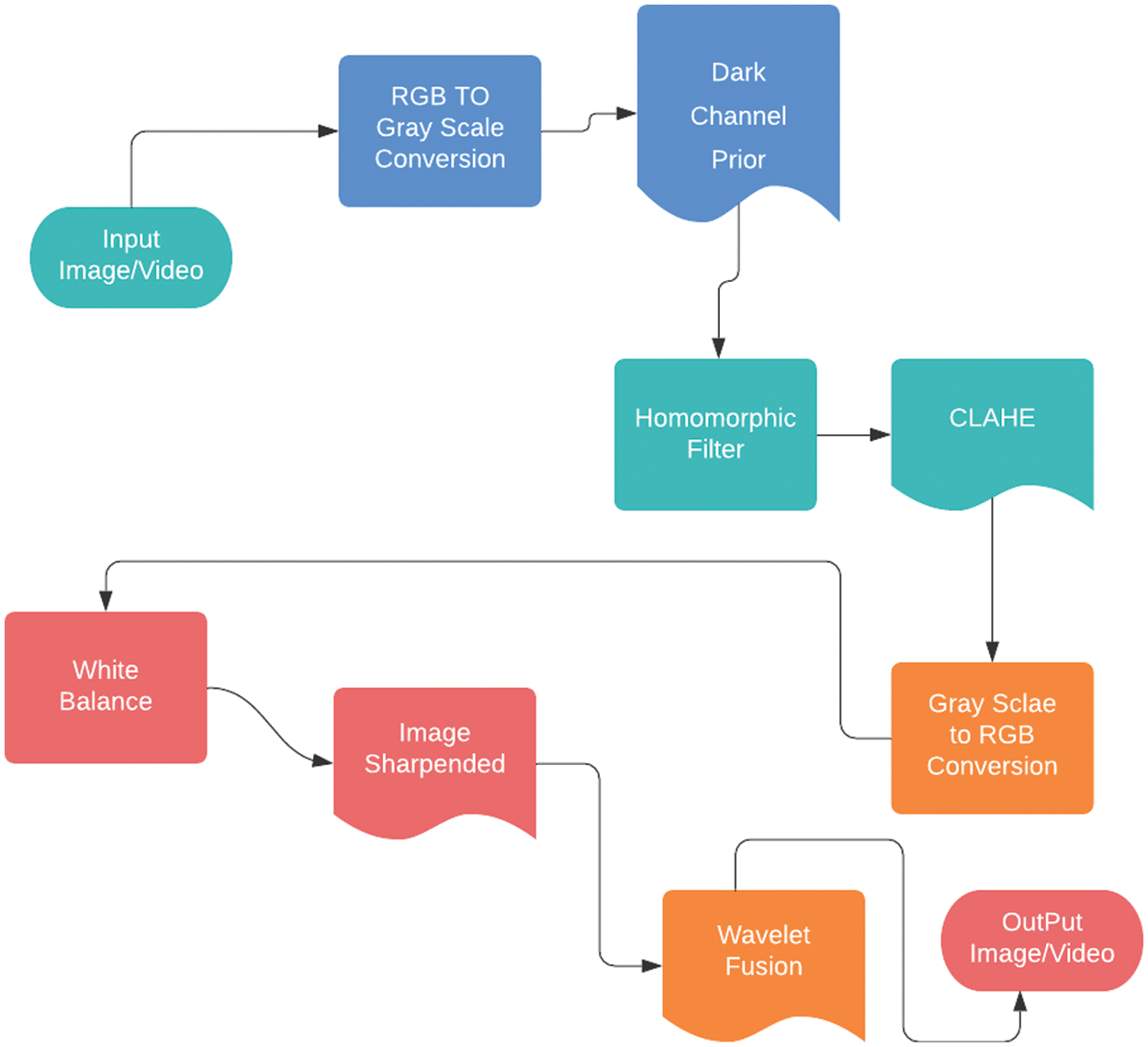
Figure 1: Proposed method
This stage typically aims to convert an RGB image or video into a grayscale image or video. Rgb2gray changes over RGB qualities to grayscale values by distributing the weighted whole of the R, G, and B segments [14]:
Above Eq. (1), show the basic RGB to grayscale conversion. Here R shows the red channel, G shows the green channel and B shows the blue channel of an image. These things combined convert an RGB image into a grayscale image.
In above Fig. 2, the first figure is an RGB image, and the next figure is the red plan of the RGB image in grayscale form similarly. The next two figures are the green and blue planes of the RGB image in the grayscale form.
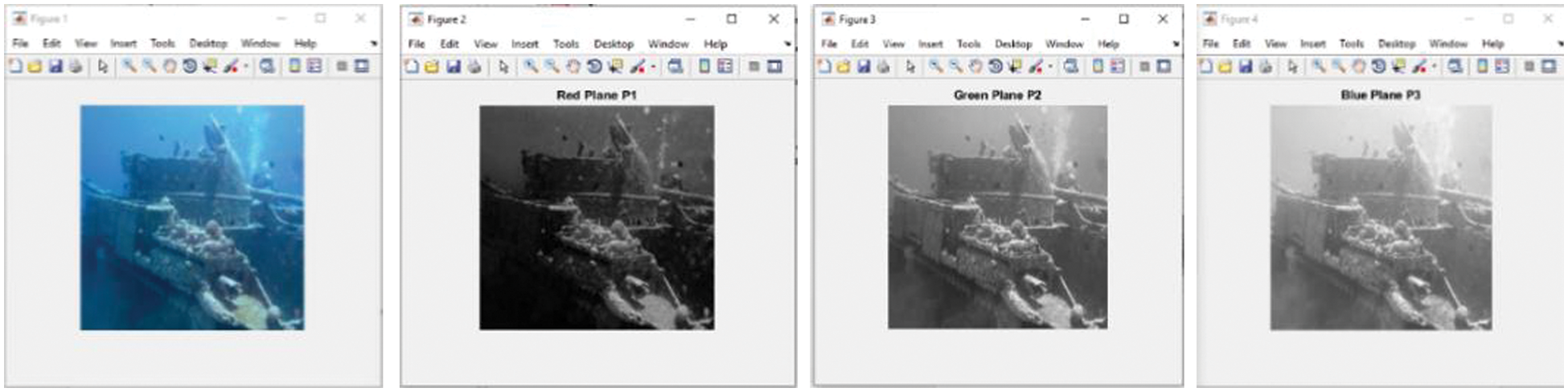
Figure 2: RGB to three-plane grayscale images
The main purpose of using a Homomorphic filter and CLAHI rather than one was to correctly enhance the image quality, and if one of them could not enhance it then the other one would be able to do it, so this way it can be applied in nearly all types of images. The homomorphic filter can easily handle noise and non-uniform light conditions which makes it a better technique for underwater images.
Above Eq. (2), shows the relation between intensity coordinates and image radius. Where i represents the intensity coordinates and r represents the radius coordinates.
Various techniques have been proposed to overcome underwater issues. Underwater images have various issues which include less light available as water is 800 times denser than air which causes a color absorption effect. These things create blurriness, low contrast, color diminishing, and less visibility. Due to these problems in underwater images, research finds it one of the most difficult areas in research. To overcome these issues a new method is proposed in this study. Initially, the white balancing technique was developed to check the effects on underwater images. Fusion produces better results and removes color cast from images. Initial results of input images are given below:
where Cb (i, j) is known as the chromaticity values of pixel (i, j) and N represents the number of pixels that are used in the calculation.
The Contrast Limited Adaptive Histogram Equalization (CLAHE) works on small blocks in the picture that are called tiles, as opposed to the full picture [4]. Every tile’s difference is improved, with the aim that the histogram of the yield area around matches the histogram. The neighboring tiles are then consolidated utilizing bilinear interjection (which resamples information and introduces information to every pixel. Bilinear interpolation is a process for ascertaining estimations of a matrix area that depends upon close-by lattice cells. The key contrast is that it utilizes the FOUR closest cell centers. It also uses 16 nearest neighbor pixels used to smooth the surface of all the pixels) to dispose of falsely initiated limits.
For the histogram, H (i) its cumulative distribution H’ (i) is:
To use the above equation as a remapping function, we need to normalize the H’ (i) in such a way that the maximum value should be equal to 255 (or equal to the maximum values of intensity in images).
White balancing is the technique to remove unreasonable shading throws, with the goal that objects which seem white should render white in your photograph. We need to convert the input image to grayscale so we can get the mean luminance and then extract individual red channel, green channel, and blue color channels. After that, we need to calculate the same mean for every channel and then combine the red, blue, and green channels into a single true RGB channel.
where Rwb, Gwb, and Bwb are known as the output signal, Ro, Go, and Bo represents the Red, Green, and Blue output signals of the camera. Here A1, A2, and A3 represent input images. Here we need different input images for each channel processing and then combine them with fusion to get a better resultant image.
Haze-free image is based on the dark channel prior where one or more than one channel of color has some pixels whose intensity levels are low or near to zero in non-sky patches. In the literature, it is observed that several research studies highlight the haze issues in underwater images. So, to overcome this issue this study also applies DCP. A grayscale image was processed and sent to DCP for processing, and it adjusted the intensity of each pixel. For an arbitrary image J, its dark channel is given by:
where Jc is the color channel of J and
Human observation is exceptionally touchy to edges and fine subtleties of a picture, and since they are made principally by high recurrence segments; the visual nature of a picture can be gigantically debased if the high frequencies are constricted or finished evacuated. Conversely, upgrading the high-recurrence segments of a picture prompts an improvement in the visual quality [9].
Fusion is a way of combining two or more images into a single image. This resulting single picture has more details and is more precise than any other single source picture, and it contains all the important information about the image [10]. The reason for image combination isn’t just to lessen the data information yet in addition to build images that are increasingly fitting and justifiable for human and machine perception. Wavelet fusion is the way of joining significant data from at least two images into a solitary picture. Wavelet fusion is applied to an image at the end of all processes and enhanced images were given to it and it then combines them and produces the final image.
4 Results of Proposed Framework
The Japan Agency for Marine-Earth Science and Technology (JAMSTEC) collected various pictures and videos from the deep sea for research purposes. To verify the performance of the proposed framework various experiments are performed on the JAMSTEC [15], and KAIKO ROV data sets (JAMSTEC contains more than 10,000 underwater images and KAIKO ROV contains more than 7000 depth images). KAIKO remotely operated underwater vehicle (ROV) built by the Japan Agency for Marine-Earth Science and Technology (JAMSTEC) for exploration of the deep sea collected Deep sea images. Eight images are also collected from the internet resources [16] to perform the experiments. So there was a total of 17008 images in the data set to perform experiments.
Fig. 3. shows input image enhancement in steps. As seen in the figure initially image is converted to grayscale and then DCP is applied to it and after that CLAHE is applied to the resultant image. This resultant image is now white balanced and sharpened to have better features and finally, wavelet fusion is applied to it to obtain a better output image. To assess the performance of the proposed framework at each step, the results are measured after each step which is presented in Table 1.
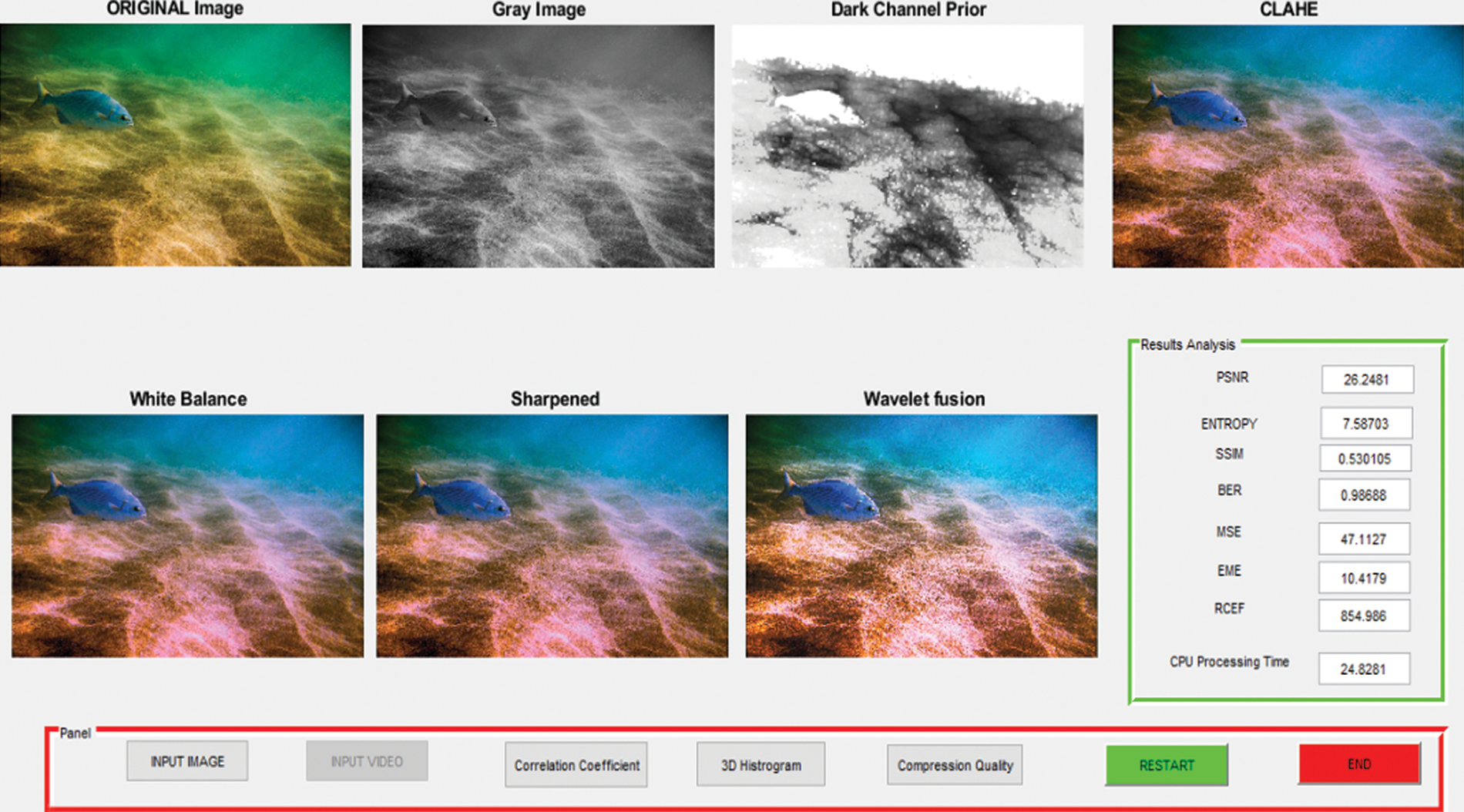
Figure 3: Visual results of the proposed framework

Above Table 1 shows the values of performance parameters achieved at every step by the proposed framework. These achieved Values of performance parameters indicate better results produced in each step.
To check the performance of the proposed framework following performance parameters are used.
• Measure of Entropy (MOE)
• Measure of Enhancement (EME)
• Mean Square Error (MSE)
• Peak Signal to Noise Ratio (PSNR)
Entropy is a statistical parameter that indicates the randomness in image texture. Entropy H (I) of an image is defined as
Here P (i, j) is the possibility of occurring of any pixel’s intensity values with spatial coordinates (i, j). If the randomness in texture is high then variation in pixel intensity is also high. However, the value of randomness is not a characteristic of underwater images and it arises due to the unnatural color present in the underwater environment. This decreases results for entropy and produces lesser entropy for images. Intuitively, once underwater images were enhanced, it would result in higher average information by increasing the intensity variation. To verify the information about an underwater image, the entropy of the enhanced image can be increased for all types of images. The main reason for the underperformance and bad results of the GW and APE methods is that they are mainly based and focused on blind color equalization.
4.2 Measure of Enhancement (EME)
Another quality metric proposed by Weber was a contrast-based measure of enhancement also known as the “no-reference image quality assessment” (NR-IQA) metric to quantify the value of the contrast enhancement obtained in images. EME value also signifies the contrast quality improvement after enhancement; we used it in the present context as a quantitative NR-IQA parameter.
Here CR represents the minimum and maximum intensities in an image block,
The mean squared error (MSE) of an estimator measures the average of the squares of the errors that is, the average squared difference between the estimated values and what is estimated. MSE is also calculated by comparing the original image and the noisy (compressed image) which produced results for MSE. MSE is also known as the risk function that corresponds to the expected value of squared error loss. MSE always remains positive and not zero is mainly due to randomness. Minimum the value of MSE shows minimum error.
In the above equation, M represents the number of rows and N represents the columns in the images.
4.4 Peak Signal-to-Noise Ratio (PSNR)
Peak Signal-to-Noise Ratio, also known as PSNR, is an engineering terminology that represents the ratio of the highest power of a signal and the maximum power of corrupting noise that affects the value and its representation. Many signal values have a wide dynamic range so PSNR can be expressed in terms of the logarithmic decibel scale. Values of PSNR block compute the peak signal-to-noise ratio in decibels among any two input pictures. This ratio is mostly used as a quality measurement between the original and a compressed image. It has been observed that the higher the value of PSNR, the higher the quality of the enhanced image, or reconstructed image. The Mean Square Error (MSE) and the Peak signal-to-noise Ratio (PSNR) are the two mainly used error metrics used for comparison between compression qualities of images. The MSE value represents the total squared error among compressed and original images, whereas PSNR represents a measure of the highest error. A minimum value of MSE shows the minimum error, and the higher value of PSNR shows better image quality.
To compute the value of PSNR, first, calculate the mean squared error by the following equation:
In the above equation, M represents the number of rows and N represents the columns in the images. After that the block calculates the PSNR using the following equation:
In this above Eq. (11), R is known as the max fluctuation in the input picture data type. Like, if the images have more than one floating-point data type then we can assume R is 1. If the values contain an 8-bit unsigned integer data type, then R is 255. This takes one input image and introduces the noise in it and then compares it with the original image for quality measurement. Initial pictorial results can be seen in Fig. 4.

Figure 4: Initial result of the proposed model
Fig. 4 shows input image enhancement with the fusion technique which combines multiple input images into a single composite output image. The output image appears to be better than the input image and the foreground of the image is enhanced. As shown in the above Fig. 4 there is no sign of greenish effects in the output image.
The greenish effect is caused by the color cast which was removed by using the Fusion technique. This technique can even produce better results when combined with the Adaptive color balancing technique. The next image mainly contains bluish-green effects, and the resultant image appears to correct this to some extent. However, to fully remove it, a complete proposed method needs to be implemented.
Fig. 5 shows color cast improvement in the input image. In the above image greenish region in the foreground is removed with the fusion technique. Finally, a blue hazy image can be corrected with fusion and color balancing technique as shown in following Fig. 6:
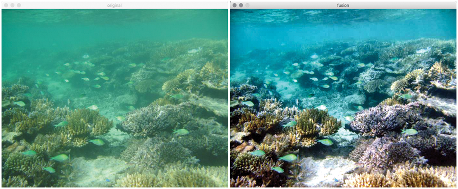
Figure 5: Color cast results
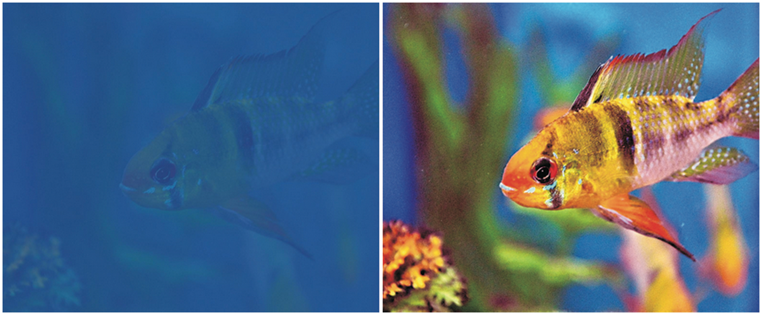
Figure 6: Color cast results
Above Fig. 6, shows color cast improvement in the input image and removes any bluish effects present in the image. Here blue region was present in the input image and it was removed through this method.
4.5 Static Image Comparison (JAMSTEC & KAIKO ROV Datasets)
Most of the researchers used images from the internet to assess the performance of their proposed techniques. However, some of them used JAMSTEC dataset to perform experiments. Fig. 7 shows the comparison between the proposed method and current literature that used JAMSTEC datasets.
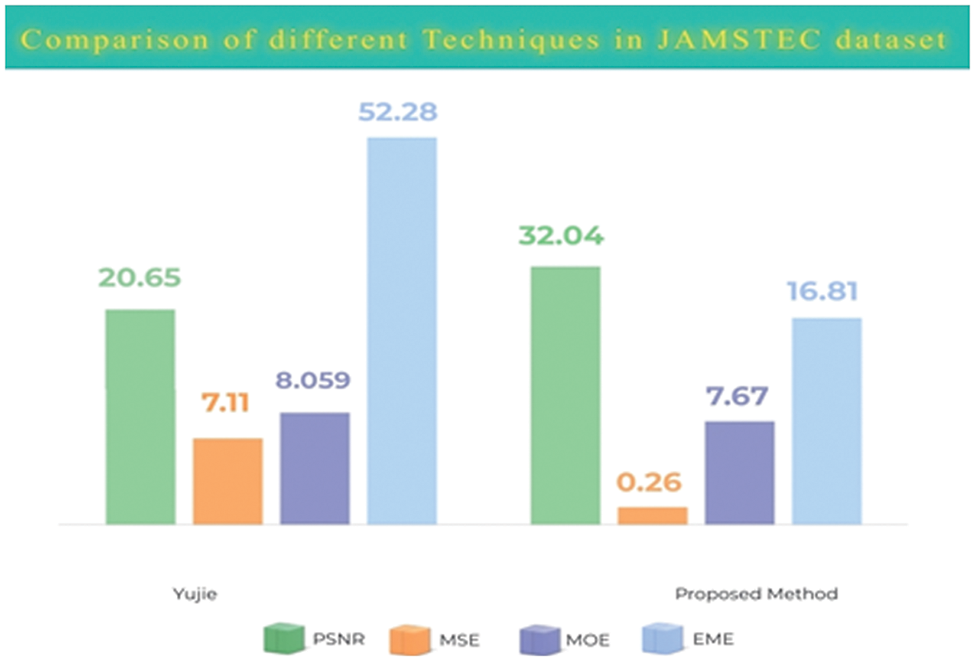
Figure 7: Comparison chart for JAMSTEC images dataset
Fig. 7 shows the results of the proposed model on the JAMSTEC and KAIKO ROV datasets. The results are compared with the researcher’s work those used JAMSTEC & KAIKO ROV dataset. Our result produces better values for PSNR on the JAMSTEC. For the JAMSTEC dataset, this method produces higher values than any other method. The result of the proposed method shows less value of MSE which means less error in the output image. Our system produces fewer MSE values as compared with state-of-the-art techniques. The lower value of Mean Square Error means higher image quality. Less error also means preserving quality. This method also produces better results for EME. This indicates greater image quality improvement as compared to other methods.
4.6 Static Image Comparison (Internet Images)
Nearly every researcher used images from the internet. There are nearly 8–10 images that are used by the researcher for testing the results. We have also selected 8 images for testing purposes. The results are shown in Fig. 8:
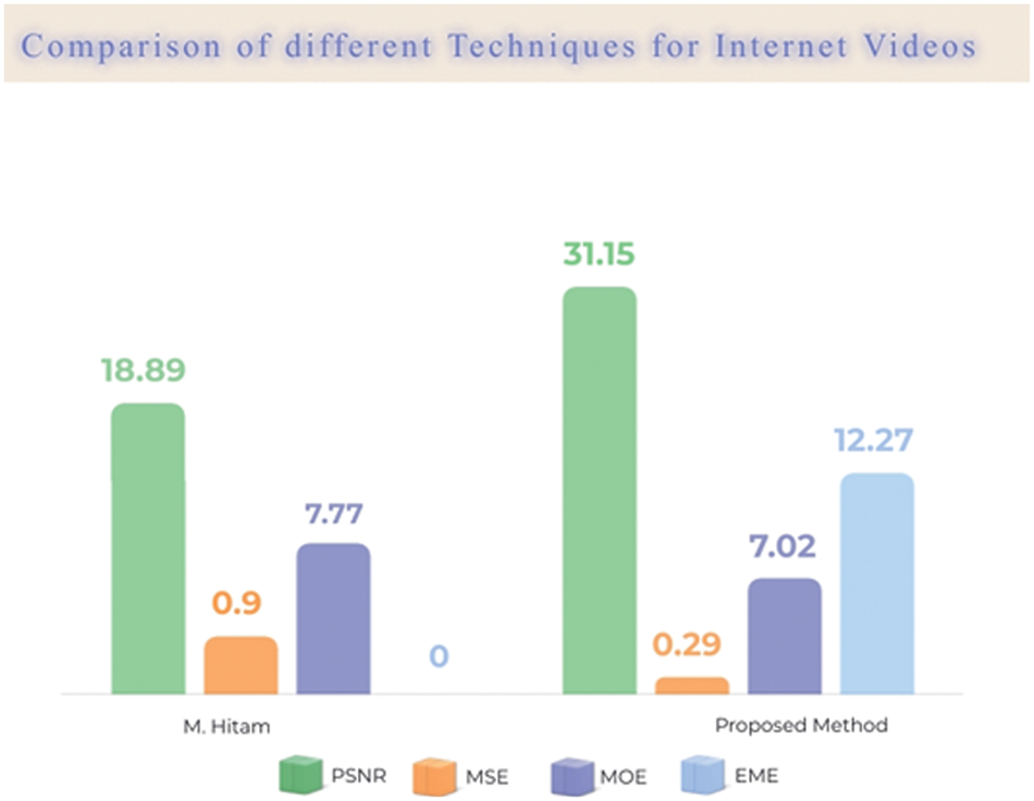
Figure 8: Result comparison graph for internet images
Fig. 8 shows the results of the proposed model for internet images. These experiments were processed on random images from the internet. The result of the proposed framework compared with the result of those papers that used these types of images for testing purposes. The proposed method produced better values for PSNR. Compared to others our method has a higher value for images.
The proposed method also shows less value of MSE which means less error in the output image and better image quality. For internet images values came out to be 0.28 which is less than any other method.
In addition, it produces better results for EME. This indicates greater image quality improvement as compared to other methods. MOE values came out to be better than some researchers and less to only one [10]. So to summarize this proposed method produces better values for internet images.
To further validate the performance of the proposed framework the proposed technique was also applied to videos. Experiments are performed on the KAIKO ROV video repository and random underwater videos taken internet. Different techniques are applied to each frame to enhance the video and each performance parameter is checked accordingly to measure enhancement.
Above Fig. 9 shows the output of video frame by frame going through each process and generating enhanced video frames. The result of the proposed framework for the video data set is compared with previous well-known techniques as shown in Table 2.
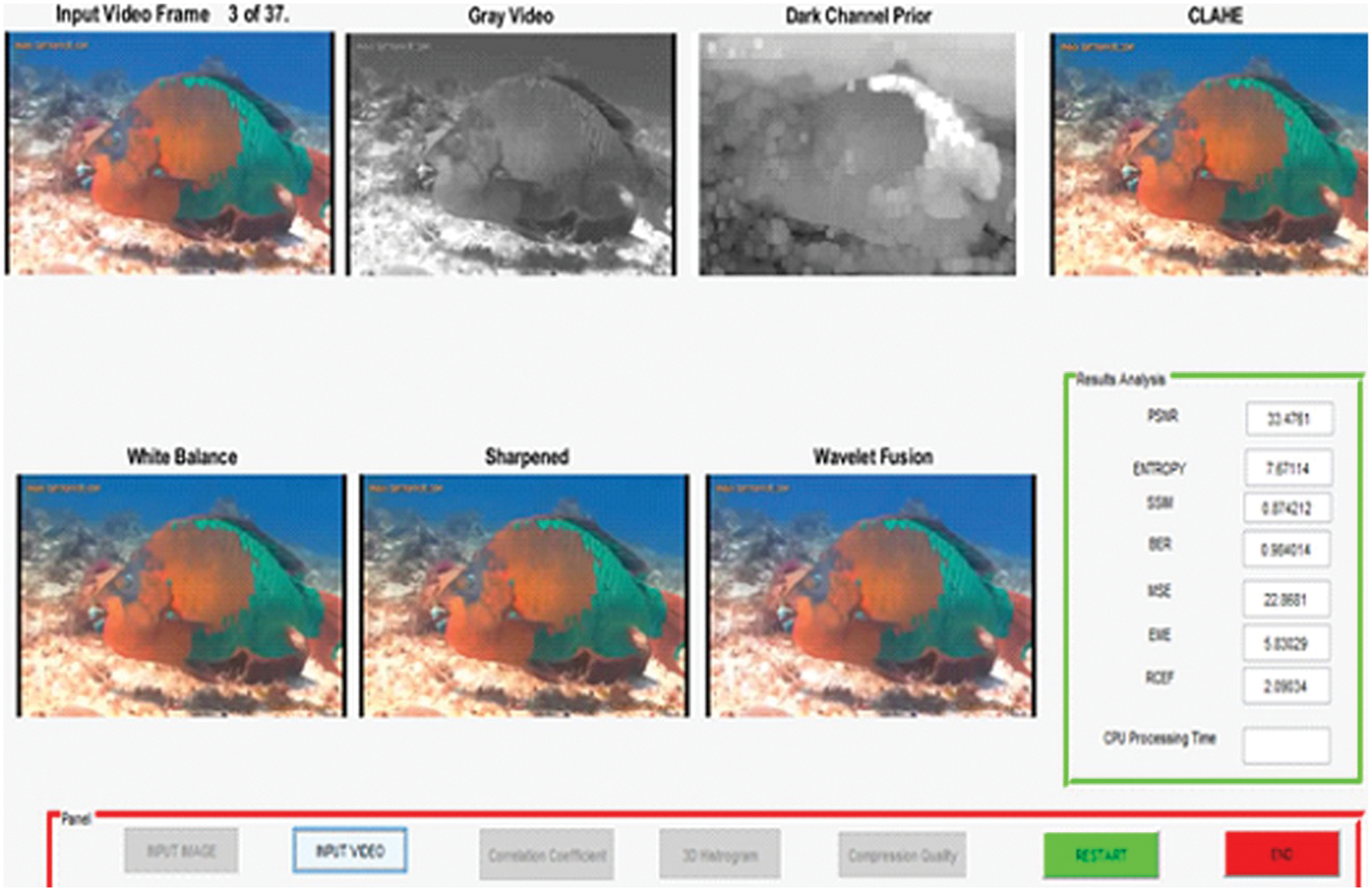
Figure 9: Visual results of proposed framework (Video)
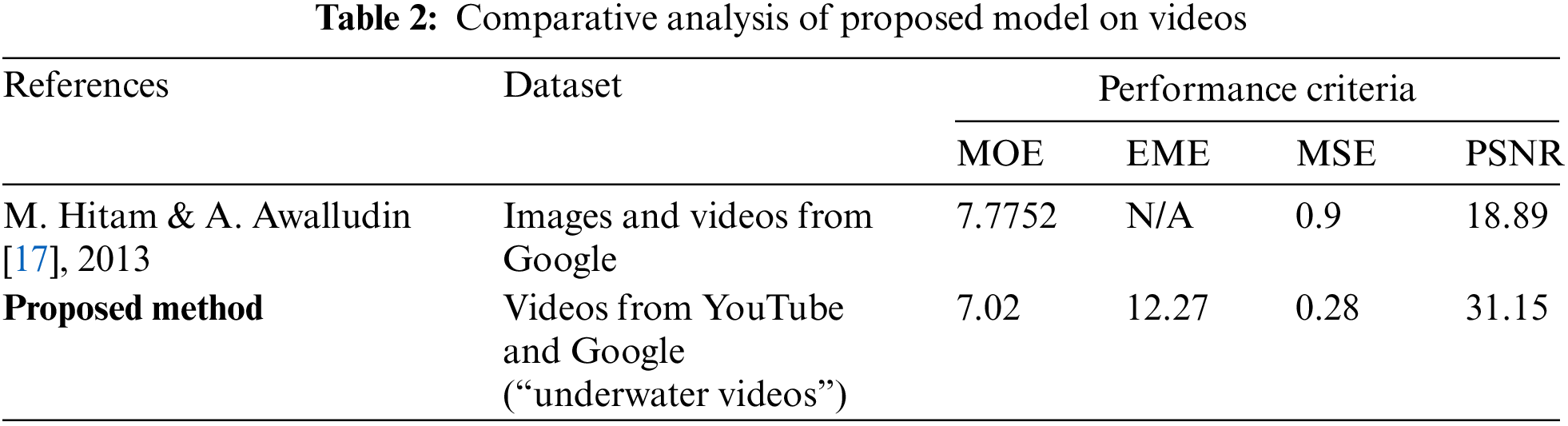
The proposed framework is evaluated on various videos and the output is presented in Table 2 and Fig. 10. Our result produces better values for PSNR on videos. For videos, this method produces higher values than any other method.
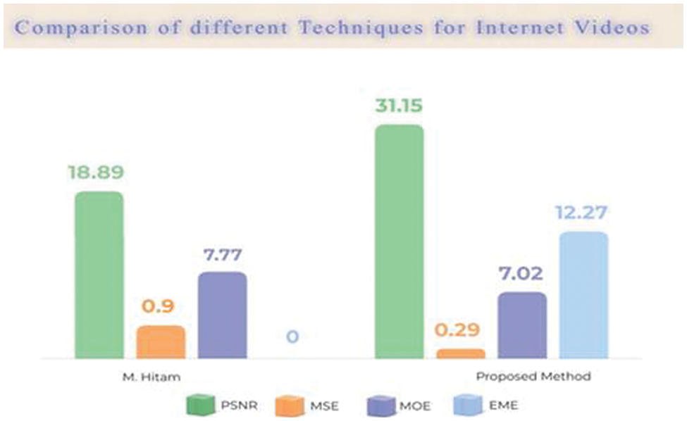
Figure 10: Result comparisons on the video data set
The proposed method shows less value of MSE which means less error in the output video. Our system produces less MSE compared to other methods. This method also produces fewer errors for videos.
Our method produces better results for videos, and no such preprocessing is required. MOE shows average results for images but for videos this method produces a higher value than any other method.
This method also produces a better result for EME. That indicates greater image quality improvement as compared to other methods. So overall all the values are better than the other methods.
Most of the researchers used Dark channel prior (DCP) in their approaches because it produces a higher value for Peak signal to noise ratio (PSNR) but it decreases contrast and produces a halo region. To overcome this problem CLAHE was used. After carefully considering the limitations of current methods for color correction, adaptive color correction has been presented in this literature which removes color cast and restores natural color.
Underwater images are very important for discovering new species or for photography purposes, studying fishes, and coral reefs, capturing 3D bathymetry of seafloor terrain and finding aquatic plants or saving them from extinction, etc. Underwater images suffer from low contrast, lighting conditions, underwater depth, absorption and scattering effect, low resolution, and color diminishing. This paper contains information about different underwater image enhancement techniques with their advantages and limitations. These techniques are evaluated on different performance parameters and depending upon those criteria, some techniques work best to improve visual quality and increase contrast. Only a few of the current methods handled color cast to some extent. Various researchers used Dark channel prior (DCP) in their approaches because it produces a higher value for Peak signal-to-noise ratio (PSNR) but it decreases contrast and produces a halo region. To overcome this problem CLAHE was used. After carefully considering the limitations of current methods for color correction as it overcomes the limitations of global approaches by performing local enhancement. Hence this method can be applied to a large range of images having a color cast, low contrast, and visual quality issues.
The major achievement of the proposed method is the enhanced underwater images as shown by the values of a performance parameter of underwater videos are higher for PSNR and MSE. A better value of PSNR indicates the output image has better visual quality and the mean square error of the output image is less than the previous methods. Our method improves the visual quality of underwater images better than the current methods.
The results show the potential of the proposed framework for underwater images on large datasets or videos. Our method produces higher values for PSNR, low error, and improved image quality. However, due to time constraints, the proposed framework is not developed for real-time application. There can be many future directions from this point on in this research. In the future, it can be implemented for real-time applications, and it has great potential to apply to mobile phone applications.
Acknowledgement: Researchers Supporting Project Number (RSP2022R458), King Saud University, Riyadh, Saudi Arabia.
Funding Statement: Researchers Supporting Project Number (RSP2022R458), King Saud University, Riyadh, Saudi Arabia.
Conflicts of Interest: The authors declare that they have no conflicts of interest to report regarding the present study.
References
1. P. P. Madhumatke and P. Agarwal, “Underwater image enhancement techniques: A review,” International Journal for Research in Applied Science & Engineering Technology (IJRASET), vol. 5, pp. 5–10, 2017. [Google Scholar]
2. K. Kaur and M. Bansal, “A review on different underwater image enhancement approaches,” International Journal of Advanced Research in Computer Science (IJARCS), vol. 9, pp. 250–260, 2018. [Google Scholar]
3. R. Kaur and A. Taqdir, “Image enhancement techniques a review,” International Research Journal of Engineering and Technology, vol. 3, no. 3, pp. 1308–13015, 2016. [Google Scholar]
4. L. Zheng, S. Sun and H. Shi, “Underwater image enhancement algorithm based on CLAHE and USM,” in IEEE Int. Conf. on Information and Automation (ICIA), Ningbo, China, pp. 585–590, 2016. [Google Scholar]
5. H. Lu, Y. Li, X. Xu, J. Li, S. Serikawa et al., “Underwater image enhancement method using weighted guided trigonometric filtering and artificial light correction,” Journal of Visual Communication and Image Representation, vol. 38, no. C, pp. 504–516, 2016. [Google Scholar]
6. L. K. Chouthmol and S. S. Bhagwate, “Enhancement of underwater images by image fusion using Wavelet decomposition,” International Journal of Scientific Research Engineering & Technology, vol. 12, no. 8, pp. 100–112, 2014. [Google Scholar]
7. D. Dev and S. Natrajan, “Underwater image enhancement for improving the visual quality by CLAHE technique,” International Journal of Scientific Research Engineering & Technology, vol. 21, no. 3, pp. 115–125, 2015. [Google Scholar]
8. S. Wong, R. Paramesran and A. Taguchui, “Underwater image enhancement by adaptive gray world and differential gray-levels histogram equalization,” Advances in Electrical and Computer Engineering, vol. 3, no. 2, pp. 109–116, 2018. [Google Scholar]
9. C. O. Ancuti, C. Ancuti and C. D. Vleeschouwer, “Color balance and fusion for underwater image enhancement,” Proceedings, IEEE Transactions on Image Processing, vol. 27, no. 1, pp. 379–393, Jan. 2018. [Google Scholar]
10. J. Banerjee, R. Ray, S. Krishna, S. N. Shome and S. Nandy, “Real-time underwater image enhancement: An improved approach for imaging with AUV-150,” Sadhana, vol. 41, no. 2, pp. 225–238, 2015. [Google Scholar]
11. C. Li, J. Guo and R. Cong, “Underwater image enhancement by de-hazing with minimum information loss and histogram distribution prior,” IEEE Transactions on Image Processing, vol. 25, no. 12, pp. 5664–5677, 2016. [Google Scholar]
12. S. Emberton, L. Chittka and A. Cavallaro, “Underwater image and video de-hazing with pure haze region segmentation,” Computer Vision and Image Understanding, vol. 168, pp. 145–156, March 2018. [Google Scholar]
13. R. Singh and M. Biswas, “Hazy underwater image enhancement based on contrast and color improvement using fusion technique,” Image Processing & Communications, vol. 22, pp. 31–38, 2017. [Google Scholar]
14. R. C. Gonzalez, R. E. Woods, and S. L. Eddins, Digital Image Processing Using Matlab, NV, USA: Gatesmark Publishing, 2009. [Online]. Available: https://www.amazon.com/Digital-Image-Processing-Using-Matlab/dp/0070702624. [Google Scholar]
15. T. Sasaki, S. Azuma, S. Matsuda, A. Nagayama, M. Ogido et al., JAMSTEC E-Library of Deep-Sea Images (J-EDI) Realizes a Virtual Journey to the Earth’s Unexplored Deep Ocean, USA: American Geophysical Union, Fall Meeting, abstract id. IN23C-1530, 2012. [Online]. Available: http://www.godac.jamstec.go.jp/jedi/e/index.html. [Google Scholar]
16. N. Hassan, S. Ullah, N. Bhatti, H. Mahmood and M. Zia, “The Retinex based improved underwater image enhancement,” Multimedia Tools and Applications, vol. 80, no. 2, pp. 1839–1857, 2021. [Google Scholar]
17. Y. Li, L. Huimin, L. Jianru, L. Xin, L. Yun et al., “Underwater image de-scattering and classification by deep neural network,” Computer Vision and Image Understanding, vol. 54, pp. 68–77, 2016. [Google Scholar]
Cite This Article
 Copyright © 2023 The Author(s). Published by Tech Science Press.
This work is licensed under a Creative Commons Attribution 4.0 International License , which permits unrestricted use, distribution, and reproduction in any medium, provided the original work is properly cited.
 Downloads
 Citation Tools