
 Submit a Paper
 Propose a Special lssue
 Open Access
ARTICLE

Optimal Management of Energy Storage Systems for Peak Shaving in a Smart Grid
1 Department of Mechanical Engineering, Al-Zaytoonah University of Jordan, Amman, 11733, Jordan
2 Department of Energy Engineering, Zarqa University, Zarqa, 13133, Jordan
3 Department of Electrical and Electronics Engineering, Faculty of Engineering and Architectures, Nisantasi University, Istanbul, 34398, Turkey
4 Department of Electrical Engineering, Jouybar Branch, Islamic Azad University, Jouybar, Iran
5 Renewable Energy Research Centre (RERC), Department of Teacher Training in Electrical Engineering, Faculty of Technical Education, King Mongkut’s University of Technology North Bangkok, 1518, Pracharat 1 Road, Bangsue, Bangkok, 10800, Thailand
* Corresponding Author: Mehrdad Ahmadi Kamarposhti. Email:
Computers, Materials & Continua 2023, 75(2), 3317-3337. https://doi.org/10.32604/cmc.2023.035690
Received 31 August 2022; Accepted 14 January 2023; Issue published 31 March 2023
 View Full Text
 Download PDF
Abstract
In this paper, the installation of energy storage systems (EES) and their role in grid peak load shaving in two echelons, their distribution and generation are investigated. First, the optimal placement and capacity of the energy storage is taken into consideration, then, the charge-discharge strategy for this equipment is determined. Here, Genetic Algorithm (GA) and Particle Swarm Optimization (PSO) are used to calculate the minimum and maximum load in the network with the presence of energy storage systems. The energy storage systems were utilized in a distribution system with the aid of a peak load shaving approach. Ultimately, the battery charge-discharge is managed at any time during the day, considering the load consumption at each hour. The results depict that the load curve reached a constant state by managing charge-discharge with no significant changes. This shows the significance of such matters in terms of economy and technicality.Keywords
The Use of a smart grid improves the accessibility to electricity, especially during peak load hours. In other words, using such a grid helps control the amount of load inflicted on the grid and reduces the possibility of power outage in different parts of the grid by preventing customers’ electricity over-use during peak hours. In addition, the quality of supplied electricity to the customers improves [1–5].The electricity price is higher during peak load hours compared to other times of the day. If we present the electricity prices to the consumers, they will be able to manage their electricity consumption. In other words, they can shift non-necessary expenditures to off-peak hours and reduce their electricity consumption during peak load hours where electricity price is high. By providing an infrastructure connecting the electric companies and consumers, the smart grid enables the electric companies to present information associated with electricity prices to the consumers. Despite the current highly equipped and advanced power grid, it is not complete and some of its approaches need fundamental changes [6,7].
With the help of information and communication infrastructure, the smart grid can help us achieve our goals. While generating required electricity during peak load hours is one of the most important concerns of electric companies, peak load management is one of the major problems in power generation and distribution. Numerous objectives have been presented and investigated for smart grids; just like any other state-of-the-art technology [8–12]. One of the crucial objectives of the smart grid is peak load shaving. There are many methods that can be utilized in power grids for peak load shaving. The energy storage system (ESS) is one of these methods and is one of the required infrastructures to create and develop electricity smart grids [13,14]. The research investigates the optimal installation and placement of the storage in the smart grid and will show that installing the storage will help reduce the level of electricity consumption during peak load hours. By taking into consideration the increasing electricity generation cost, electricity should be put to use immediately after being generated. Electricity storage is a costly process, which has to be done with the economic imposition of electricity trading [15–19].
Numerous studies have been conducted in recent years in the field of energy storage systems by the introduction of smart grids and unsteady electric prices during different times of the day and the use of distributed generation resources. In this section, previous literature regarding this field is reviewed. In [20], suitable storage is determined for a wind farm. In this paper, an economic dispatch has been utilized for this objective. The objective of these studies is to maximize the profit achieved by installing distributed generation and storage for the resource owners and using them in power systems to reduce electricity costs. Results depict that using energy storage systems can help reduce the annual cost of electricity. Moreover, using energy storage systems alongside renewable energies (such as wind) can help improve the inclusion of these types of resources inside the power systems. In [21], the economic analysis method is utilized in order to find suitable storage. This method is inspired by the net present value (NPV) profit. The genetic algorithm is utilized in order to find the maximum profit achieved by NPV. A micro-grid is utilized in the study that consists of a number of distributed generation resources, e.g., solar cells, fuel cells, and micro-turbine. One of the main reasons for using storage is unsteady electricity prices during the day. In [22], temporal planning is proposed for storage by taking the time of use (TOU) condition into consideration. In this paper, particle swarm optimization is utilized. In this method, storage is considered alongside the wind farm and the impact of unpredictable wind speed is taken into consideration. Simulations are conducted on an industrial load.
The extensive use of energy storage systems is one of the objectives of electricity smart grids. In [23], the optimal performance of these systems is investigated in smart grids. In [23], the study network consists of a system with 17 buses, a solar power plant and the wind farm. The genetic algorithm is utilized to find the optimal location and capacity of capacitor and storage. Next, economic dispatch is utilized for determining the optimal performance of the storage, grid, and distributed generation resources. In [24], an optimal strategy is proposed to manage the storage for improving the performance of the wind farm. In this paper, a dynamic programming model is utilized. According to this model, the generated power by the wind farm should be able to follow the load curve. The optimization objective is to maximize the profit by the energy sale. Reference [25] determines an optimal capacity and strategy of energy storage performance for peak load shaving. Firstly, storage capacity is determined in order to reduce energy purchases from the grid. Next, storage performance strategy is determined aiming at reducing payable expenses. In this paper, simulations are conducted on an industrial load. In [26], the optimal capacity and location of the storage and the capacitor are determined with the aid of an analytical method. In this method, the objective of placement is to reduce the loss. Firstly, the optimal size of the storage is determined for each busbar in the proposed methods and then, a busbar with the lowest loss level is selected as the optimal busbar. Next, the storage is placed in that location with the optimal value, and the optimal location and capacity of the capacitor are determined in order to achieve a minimum loss.
Reference [27] introduced two PI-PSO controllers to stimulate a DVR for enhancing the on-grid hybrid system under misfire and fire-through faults. The PI-PSO controllers’ goal is to force the system voltage at the POT to control the voltage between the DVR and the load and consequently enhance the performance of the system during misfire and fire-through faults. The proposed PI-PSO controller showed a better performance concerning the system voltage, RESs’ powers, and the WECS speed, electromechanical torque, and power. The objective of [28] is to design an economic microgrid system for the Yanbu region of Saudi Arabia. This design aims to select the best microgrid configuration while minimizing both NPC and LCOE considering some technical conditions, including loss of power supply probability and availability index. The optimization algorithm used is Giza Pyramids Construction (GPC). To prove the GPC algorithm’s effectiveness in solving the studied optimization problem, artificial electric field and grey wolf optimizer algorithms are used for comparison purposes.
Determining the strategy to optimize the performance of energy storage systems is one of the problems associated with the exploitation of these systems. In [29], linear programming is utilized in order to determine the optimal performance of an energy storage system. In this paper, real-time pricing is utilized and the studies system consists of one local manufacturer, the storage, load, and grid. Since the prices are not steady (changing), the profit as a result of energy sale, energy acquired by storage from the grid and manufacturer aiming at charging, and energy supplied to the load by the storage are determined at each hour. In [30], the storage optimal location and capacity are determined aiming at improving the voltage profile. In this paper, sensitivity analysis (SA) is utilized. Simulation is conducted for an IEEE 13-bus system and it is assumed that the grid consists of solar cells. Using the energy storage improves the voltage profile considering the load variation and solar radiation at different times of the day and different seasons.
Flattening the load curve is one of the objectives of use management/control. In this paper, the use of storage is investigated aiming at reducing peak load and flattening the load curve. Considering that gas power plants are utilized in peak load conditions, this paper suggests a substitute solution, namely the energy storage, for these types of power plants. Next, a dynamic programming model is utilized in order to determine the optimal capacity and programming of storage, aiming at reducing the fuel costs of power plants. The unsteady nature of renewable energy resources causes troubles in power grids. Therefore, these types of resources are utilized alongside the energy storage. An economic method for determining the optimal storage capacity is proposed inside the micro-grid. The studies are conducted in two modes, including islanded mode and grid-connected mode. The solver is inspired by integer linear optimization (programming). The results depict that the profit achieved by the micro-grid has increased after installing the storage.
In this paper, the objective is the reduction of peak load by the installation and optimal placement of the energy storage inside the grid and managing the charge-recharge of storage resources. Hence, particle swarm optimization is utilized in order to find the location and capacity of storage resources. Next, a practical and well-rounded program is proposed in order to optimally exploit the storage at different times during the day. In Section 2, an explanation is given concerning objective function and constraints. In Section 3, swarm optimization is explained briefly. In Section 4, the results of simulations are presented and compared with simulation results achieved by previous literature. Ultimately, a summary of results and conclusion are presented in Section 5.
2 Objective Function and Constraints
Energy storage systems are among the existing technologies considered in creating and developing electricity smart grids. Hence, energy resources can be utilized as one of the impressive strategies for peak load shaving in the grid. The energy storage is one of leading load management methods in power grids. In this method, power plants always generate energy in an optimal condition of their performance and they are not required to follow the load curve. In the case of surplus energy in the grid, this energy is stored in the storage elements and then, supplied back to the grid during peak hours. In other words, storage is the realization of how the load is transferred in the power grid.
Power consumption varies at different times of the day. Considering the unsteady price of electricity at different times of the day, the storage is supplied energy during off-peak hours (low electricity price). Considering the difference between electricity prices for peak hours and off-peak hours, this matter will increase in the grid profit. Taking the above process into consideration, the ratio of loss reduction during peak hours is more than loss increment during low-peak hours. Moreover, installing storage will bear a number of costs. In this paper, the objective is to maximize profit achieved by storage installation. Cost and profit functions are given as follows for one day:
The investment costs of the storage include two types of costs, namely (1) power electronic equipment costs and (2) storage unit costs.
The annual cost includes annual investment cost, annual replacement cost, and annual maintenance cost. Annual maintenance cost sis calculated as follows [22]:
where OMF is maintenance cost per kW. Investment costs include three parts, including power electronic equipment cost, storage unit cost, and the balancing cost (grid-connected mode) of the power plant. The power electronic equipment cost is calculated as follows:
where
where
Balancing cost is as follows:
where BOPU is the balancing cost per kilowatt-hour (kWh). The total investment cost can be calculated through summation of power electronic equipment cost, storage unit cost, and power plant balancing cost:
The annual investment cost can be written as follows:
where i is the annual interest rate and y is the collection life span. In the case of using a battery in the storage unit, we may need to replace the battery during the life span of the collection. The total annual replacement cost per kWh is calculated as follows:
The number of terms in the above equation equals the number of times the battery is replaced during the life span of the collection. R is period of replacement:
where c is the number of charge-discharge cycles during battery life span. D denotes the number of days in which storage is utilized and n is the number of charge-discharge per day. Annual replacement cost equals to:
As a result, investment cost per day is as follows [23]:
Storage acquires energy from the grid during off-peak hours. This cost equals:
where
2.3 The Cost Imposed by Increased Loss
As mentioned above, storage acquires energy from the grid during off-peak hours. As a result, the loss increased during these hours. As a result, the cost of such event equals:
where
2.4 The Profit Gained by Energy Sale
During peak hours, storage supplies energy to the grid. Hence, the profit gained by energy sales equals [29]:
3 Particle Swarm Optimization (PSO)
Particle swarm optimization (PSO), better known as bird swarm algorithm (BSA), is a state-of-the-art heuristic technique that is inspired by the behavior of birds’ flock in nature. PSO is a powerful stochastic optimization algorithm that is inspired by flock movement and intelligence. In Fig. 1, the behavior of a group of birds or fishes is illustrated.

Figure 1: Foraging behavior of birds and fishes adapted from [18]
This algorithm utilized social interaction for problem solving and was developed by James Kennedy (social physiologist) and Russell Eberhart (electronic engineer). They used a number of particles forming a group and these particles are moving inside the search space to find the best solution.
A particle is considered a point inside the N-dimensional space that regulates its levitation according to its own and other particles’ levitation experience. Each particle follows its coordinates inside the solution space that is associated with the best solutions achieved by that particle so far. This value is named best person (Pbest). There is another value for the neighbor particle that is followed by the algorithm. This value is named best global (Gbest). In other words, it is considered the best global experience.
The main concept of PSO is the acceleration of each particle toward their Pbest and Gbest locations that is executed randomly each time with an accelerator, as shown in Fig. 2. In this Figure,
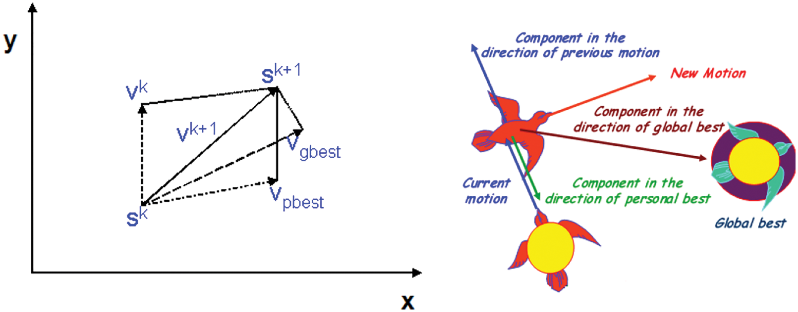
Figure 2: Concept of modification of a searching point by PSO adapted from [18]
As mentioned earlier, PSO mimics the movement of birds’ flocks. Think about the following scenario:
A group (flock) of birds are searching for food in an area in a random manner and there is only one portion of food inside the searched area. None of the birds knows the location of food but they know the distance from the food at each stage. Therefore, this problem is about finding the best strategy to find food. An effective method is to follow the birds that are closer to the food. By following such a scenario, PSO is utilized to solve the optimization problems. In PSO, each unit is considered to be similar to the one bird in the search space, which is called a particle as mentioned earlier. Two parameters are defined for all particles as follows.
• The best response (fitness) is assessed and optimized with the aid of a fitness function.
• Velocities in the same direction as particles levitation inside the problem space by following currently optimized particles.
PSO starts with a group of random particles and then, is updated with two optimal quantities. The first one is the best solution (fitness) that is found so far. This quantity is stored and named Pbest. The other quantity is the best global and is named Gbest. When a particle considers a part of the population as the location vicinities, the best quantity is transformed to the best location and named Pbest. After finding the best two quantities, the velocity and location of the particle are updated.
Each particle tries to modify its location with the following data: current position, current velocities, the distance between the current position and Pbest, and the distance between the current position and Gbest. They can be modeled with the aid of the following equation mathematically:
rand: generates a random and uniform number that is distributed between 0 and 1.
Pbest is the best location for agent i, and Gbest is the best location experienced by the swarm.
c1 and c2 are personal and collective (swarm) cognitive coefficients and their values vary between 0 and 2. However, these values are usually considered two. An increase in c1 and c2 values causes the particle to move toward personal best and converge toward the swarm’s best experience. The algorithm process is given as follows:
• Creating the initial population (swarm) and assessing it
• Determining the best personal memories and collective memories
• Updating to new velocities and positions, and evaluating the new responses
• Starting from stage 2 if the termination condition is not achieved.
• End
Particles’ velocity in each dimension achieves a maximum velocity Vmax. If the total acceleration causes the velocity to exceed Vmax, the velocity of that dimension will be limited to Vmax and the user determines this parameter. In Fig. 3, a flowchart is presented for the PSO algorithm.
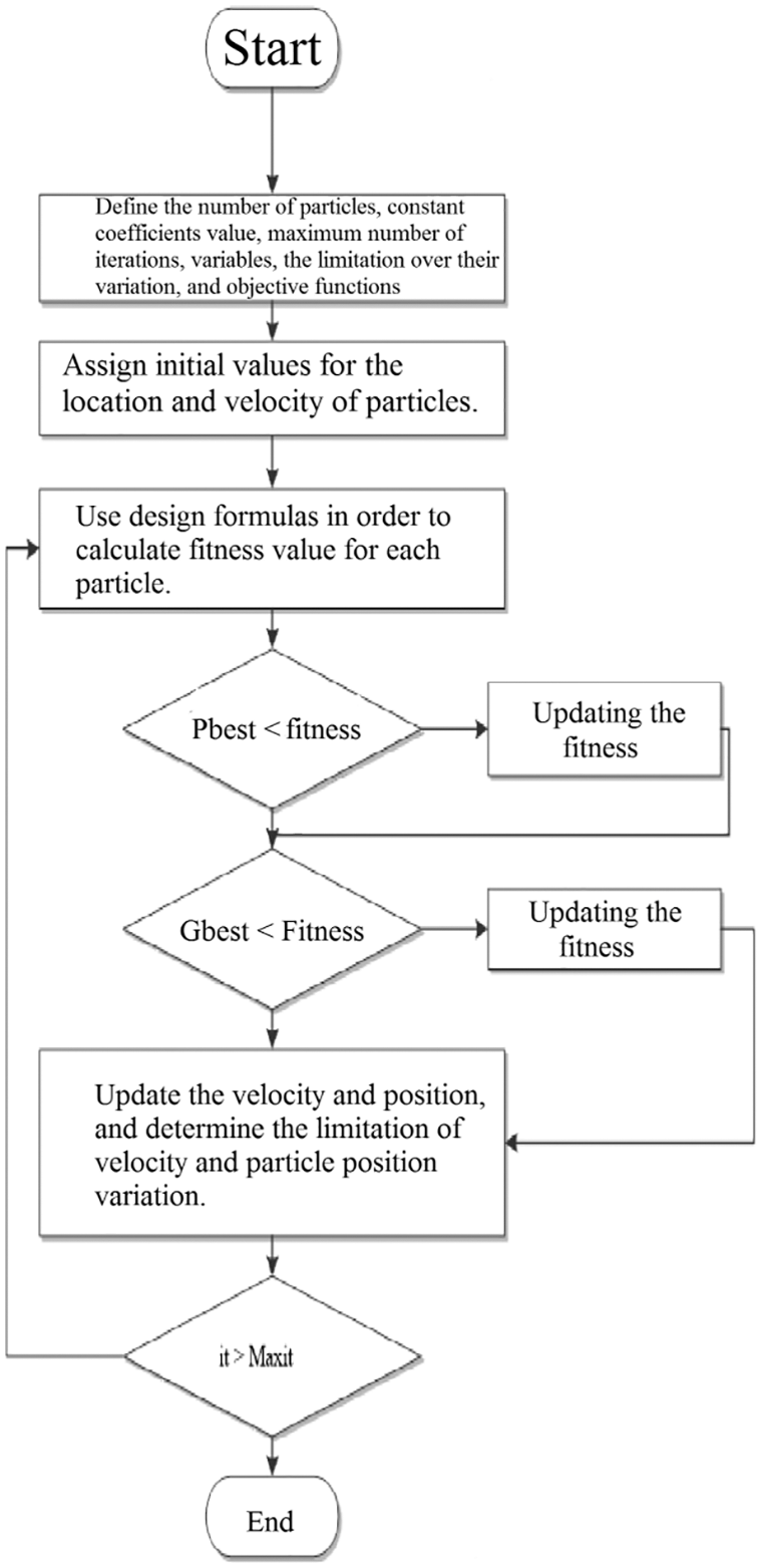
Figure 3: A general flowchart of PSO adapted from [24]
4 Simulation and Result Analysis
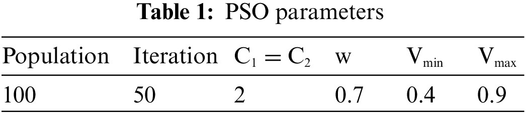
In this section, the proposed model to determine the capacity and location of storage and the charge-discharge program of these resources within the system are studied. Using particle swarm optimization, the location, capacity, and storage exploitation are investigated. Such an algorithm enjoys high accuracy. PSO parameters are presented in Table 1. Stusdies conducted in this field are aiming at decreasing the loss and peak load, increasing and the profit achieved by charging and discharging storage resources.
The grid under investigation includes a standard 33-bus distribution system. In Fig. 4, the single-linear arrangement of the system under investigation is illustrated. This is a radial grid and all the loads are fed through one pass. Active loss of the intended grid is reported to be 210.998 kW.
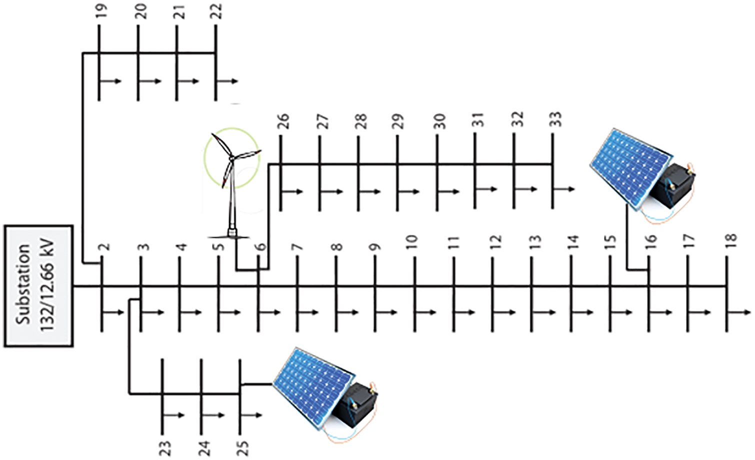
Figure 4: A single line diagram of the test system adapted from [23]
In Fig. 5, the amount of loss in all the lines without the distributed generation resources are presented. The maximum amount of loss is associated with line number 2, which is reported to be approximately 59 kW.
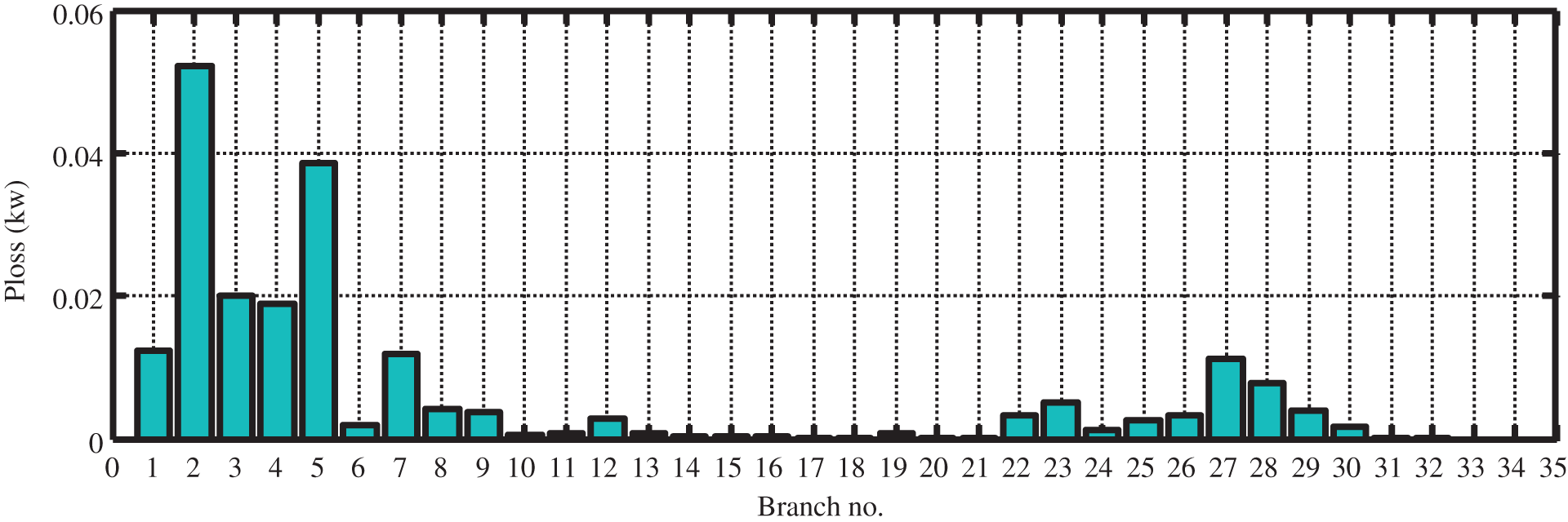
Figure 5: Line losses
In the grid under investigation, three distributed generation resources are taken into consideration. These three resources are considered in bus #6, bus #16, and bus #25 respectively, with the following capacities: 2.4878, 0.3556, and 0.7291 MW [22]. In this paper, it is assumed that the generation resource in bus #6 is a wind turbine and the other two are solar panels.
The amount of power generated from solar panels and wind turbines depends on the radiation and wind speed. As a result, radiation intensity and wind speed in the location under investigation should be determined. Radiation intensity and wind speed during 24 h of investigation are shown in Figs. 6 and 7.
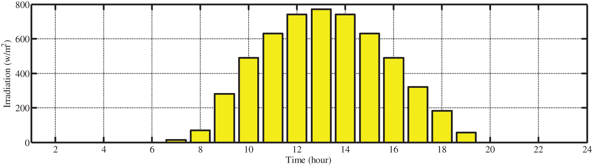
Figure 6: Solar radiation level
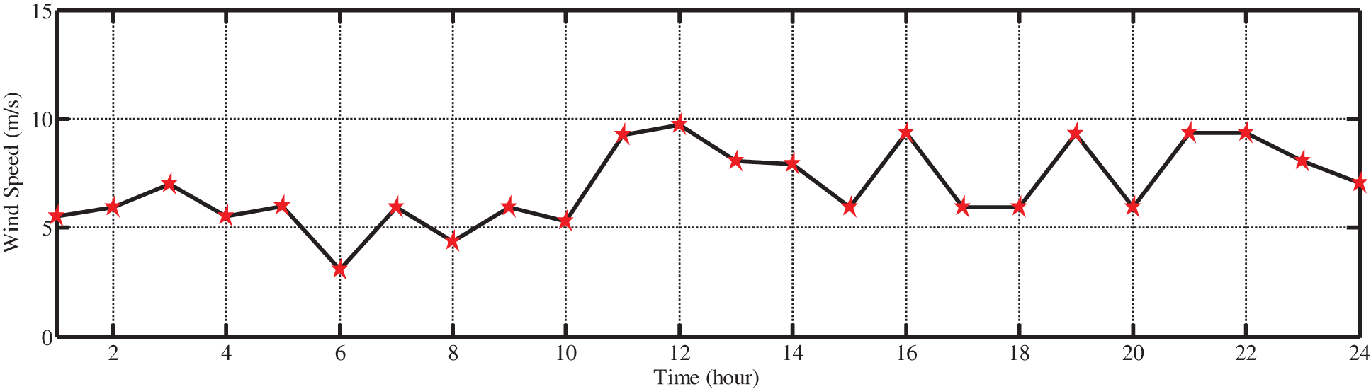
Figure 7: Wind speed
In Fig. 8, the amount of load in the grid during 24 h of investigation is shown using bar graphs in per unit. The amount of power required by the load is less than 0.4 per unit at late night and peak load occurs in around 10. The nominal power of the grid is 4.5 MW.
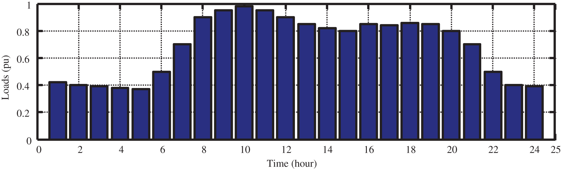
Figure 8: The power needed by load (in per unit)
Two different scenarios are utilized in this paper. In the first stage, the location and capacity of the storage are investigated aiming at reducing loss in the grid. In the second stage, this algorithm is utilized for charging and discharging these resources at the selected points, aiming at flattening the load profile.
In this section, the location and capacity of storage resources are investigated. In the simulation, it is assumed that only two areas in the grid can be utilized for storage installation and each of these areas can provide a maximum of 70 collections of installable batteries [24]. As a result, each collection of batteries can provide power equal to 7.7 kW. In addition, a maximum of 540 kW can be installed at each storage bus.
Hence, particle swarm optimization has been utilized aiming at reducing loss in the distribution system. Investigation is conducted at 10 am at the time of peak load occurrence. In the case of non-installing the storage, the amount of loss is reported to be 98.2 kW only in the presence of distributed generation resources in the system. In Fig. 9, the amount of loss for each line is presented with the aid of bar graphs.

Figure 9: Line loss prior to storage installation
The amount of loss is calculated using the following equations for power systems. If the total power injected into the busbar i is known, the total system loss will be equal to the complex power of all machines [31–37].
where N is the number of buses,
The proposed objective function is defined as Eq. (18). After the optimization process, the results depict that two storages should be installed in busbar #8 and busbar #23, with the following capacities respectively: 540 and 300 kW/h. In Fig. 10, the variation curve of the objective function (loss) is presented in 50 iterations of the algorithm.
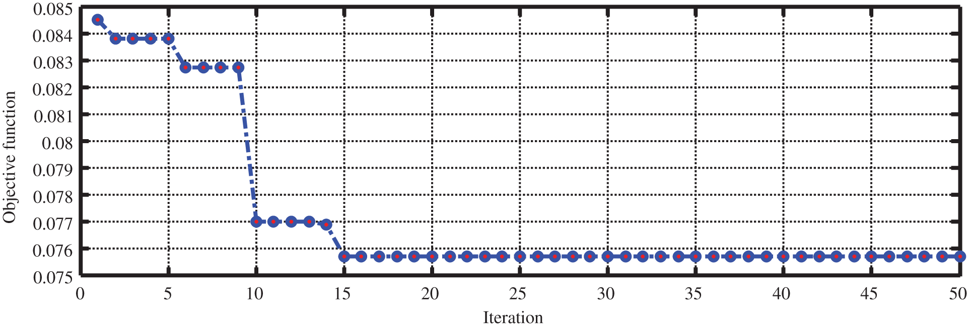
Figure 10: The best objective function value at each algorithm iteration
According to the figure, the amount of system loss has decreased to 75.5 kW after installing the storage is in the selected areas. In Fig. 11, the amount of line loss after storage installation is shown using a bar graph.
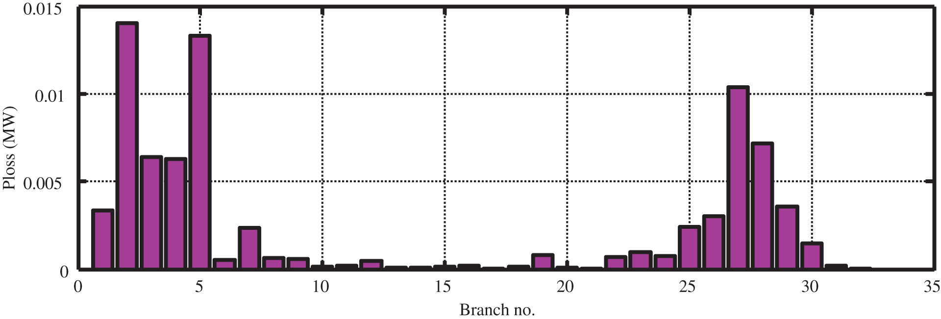
Figure 11: Line loss after storage placement and determine the capacity
A comparison between Fig. 11 with Figs. 5 and 9 illustrates the impact of storage in reducing the loss in all lines. As can be seen in Fig. 11, the loss of most lines has been decreased after storage installation and line #2 accounts for the most loss. Moreover, the amount of loss is reduced to reach one-quarter of the base conditions (non-presence of distributed generation resources and storage). In the next stage, simulations are conducted with the aid of particle swarm optimization in order to improve the load profile and flatten it. Moreover, charging and discharging of storage should be done in a way that the load profile will have the least number of difficulties and we will have an almost linear diagram.
The aim of demand response is to reduce peak load in the grid for increasing the capacity of grid spinning reserve and as a result, reduce the need to construct new power plants. Demand response can be utilized in order to reduce the level of electrical power consumption to reach maximum electricity demand efficiency and in this way, many costs can be saved. In a long term, the profit caused by reduced costs can be used to invest in new power plant [38–61]. Due to the establishment of the electricity market, electricity generation costs and electricity sale prices are different at different times of the day. For reducing grid peak load in off-load and medium-load hours (during which a high level of installed capacity is not connected to the circuit), the electricity is stored during off-peak hours (low price electricity) to be used later in peak load hours (high price electricity).
Electricity price varies at different times of the day. This paper provides simulations based on time of use (TOU). This is the most common pricing method and most countries use this method. In this method, hours in a day are divided into several periods, in each of which different prices are considered for energy. The most simple TOU method considers two periods, peak load and low-load (off-peak) hours. In some cases, medium-load hours are also taken into consideration. It is natural that the prices associated with low-load and medium-load hours will be less than peak-load hours. A sample TOU pricing is given in Table 2. The generated power by solar and wind resources are illustrated in Figs. 12 and 13 according to the resources capacity, radiation intensity, and wind speed during the 24 h of investigation.
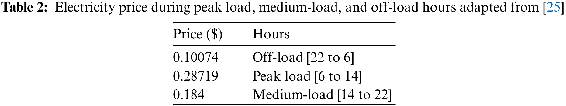
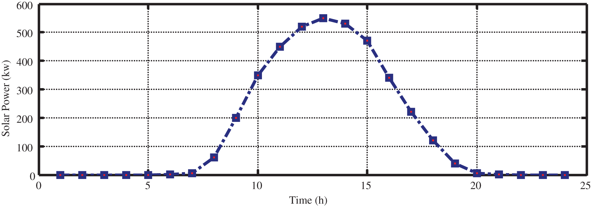
Figure 12: Solar power
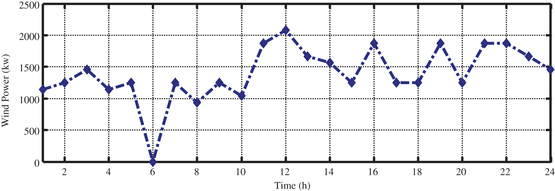
Figure 13: Wind power
As a result, the power needed by the upstream grid can be achieved as Fig. 14 by taking the amount of power generated by distributed generation resources and load in the grid under investigation into account.
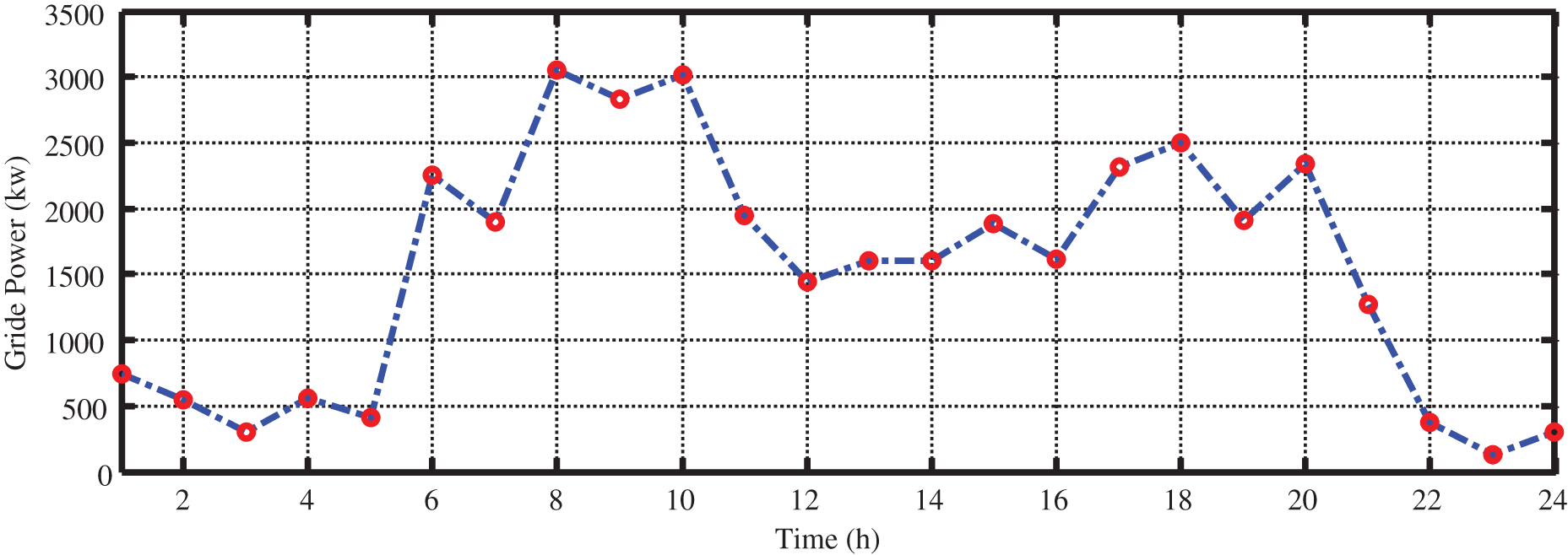
Figure 14: The amount of power demanded by the grid
As can be seen in Fig. 14, significant changes can be seen for power demanded by the upstream grid despite the presence of distributed generation resources. Hence, the storage resources can be utilized in order to reduce difficulties generated in grid power. After the optimization process with the aid of particle swarm optimization with the aim of minimizing objective function (cost), the state of charge (SOC) of two storages can be achieved as Fig. 15.
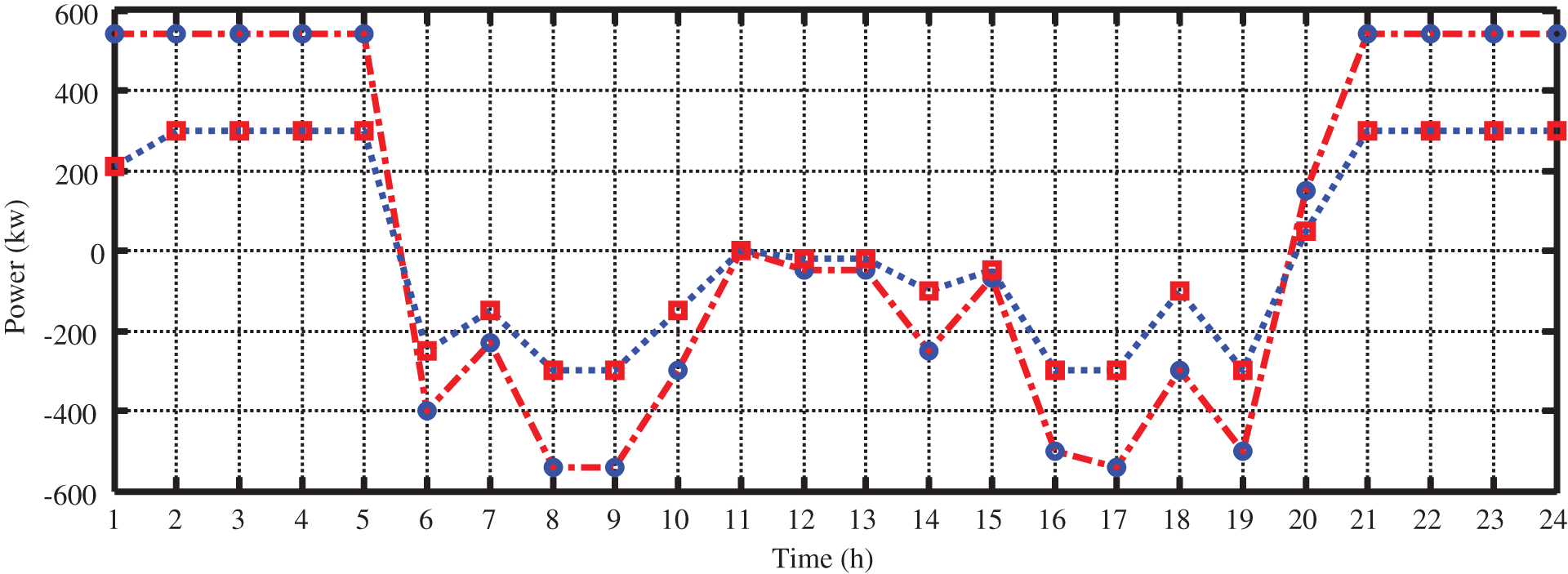
Figure 15: Charge and discharge status of each storage resource
As expected, storages stored energy at the earlier hours of the day due to low prices of electricity and then were discharged during peak load hours (6 to 24) due to increased electricity price. In the second event, the revenue achieved by electricity sales to the grid can help reduce objective function. The charge and discharge status of these two storages are illustrated in Fig. 16 during 24 h of investigation.

Figure 16: The amount of power exchange between storage and grid
Next, the genetic algorithm was utilized in order to manage storage resources, charge and discharge in the system under investigation. As a result, the charge and discharge status of the storages are achieved as Fig. 17.

Figure 17: Charge and discharge status of each storage resource
The charge and discharge status of all storages are illustrated in Fig. 18.
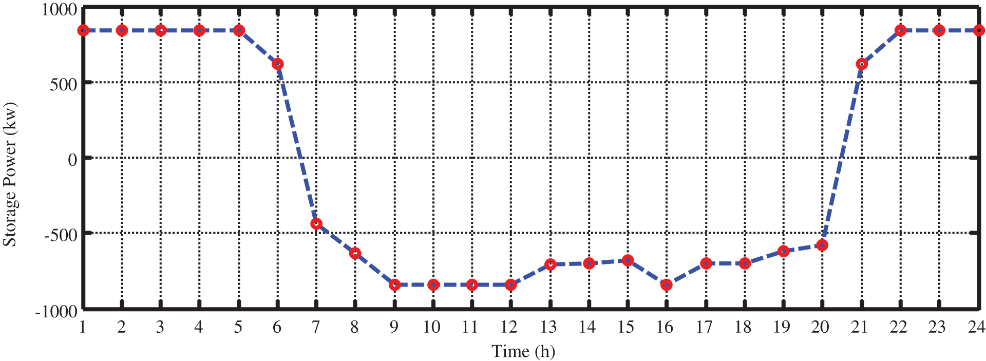
Figure 18: The amount of power exchange between storages and grid
As a result, the power profile needed for the upstream grid was changed as Fig. 19 by considering the charge and discharge status of batteries with the aid of PSO and GA.
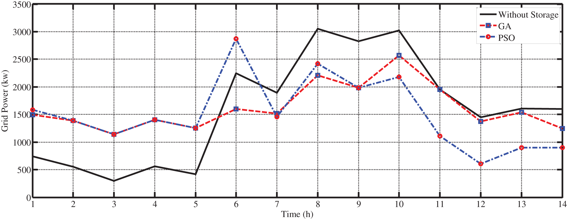
Figure 19: The amount of power exchanged with the upstream grid
According to Fig. 19, the power demanded by the grid has a more suitable status in the presence of the storage resources. During low load hours, the battery is charged as a load in the system. However, the battery is discharged as a power generation resource and this way, it will supply part of the required load. As a result, the amount of power demanded by the upstream grid will be flattened. In Table 3, the results of simulation with the aid of particle swarm optimization are presented. Moreover, the maximum and minimum amount of load and the standard deviation of the grid load are also presented. In addition, in this table, the results are compared with results of the grey wolf optimization algorithm (GWO) and Lightning Search Algorithm (LSA).
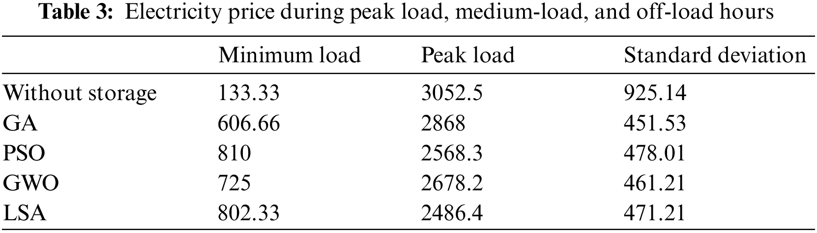
The maximum amount of load in the grid is calculated to be 810 by using the storage and managing energy with the help of PSO. However, this value is reported to be 133.33 for the system without storage. In addition, the maximum load for the system with the storage is calculated to be 2568.3 with particle swarm optimization algorithms. However, this value was calculated to be a maximum of 3052.5. The large difference between the minimum and maximum power demanded by the grid can be seen for the system without storage, compared to the low difference between the minimum and maximum power in the system with the storage. The standard deviation of variation for load demanded by the upstream grid illustrates the minimum changes in the demanded power.
In this paper, placement management, the capacity of storage resources, and energy management of resources are investigated for reducing loss and improving the load profile of the grid under investigation. Optimal installation and placement of the energy storage in the grid and charge-discharge management of storage resources have caused a decrease in peak load. Hence, particle swarm optimization is utilized to find the location and capacity of the storage resources. Simulation results were compared to the genetic algorithm. Ultimately, a well-rounded program is proposed to optimally exploit the storage at different times during the day.
Funding Statement: This work was supported in part by an International Research Partnership “Electrical Engineering—Thai French Research Center (EE-TFRC)” under the project framework of the Lorraine Université d’Excellence (LUE) in cooperation between Université de Lorraine and King Mongkut’s University of Technology North Bangkok and in part by the National Research Council of Thailand (NRCT) under Senior Research Scholar Program under Grant No. N42A640328.
Conflicts of Interest: The authors declare that they have no conflicts of interest to report regarding the present study.
References
1. M. Biabani, M. Aliakbar Golker, A. H. Zarei Kasiry and M. Akbari, “Smart grid in Iran: Driving factors, evolution, challenges and possible solutions,” in Int. Conf. on the Environment and Electricit Engineering (EEEIC), Rome, Italy, pp. 1–4, 2011. [Google Scholar]
2. S. M. Schoenung and C. Burns, “Utility energy storage studies,” IEEE Transaction on Energy Conversion, vol. 11, no. 3, pp. 658–665, 1996. [Google Scholar]
3. D. Rastler, “Electricity energy storage technology options: A white paper primer on applications, costs and benefits,” Final Report, EPRI, vol. 8, pp. 74–91, 2010. [Google Scholar]
4. C. N. Huang, “Autonomous control of energy storage devices for enhancing power system stability,” in IEEE/PES Power Systems Conf. and Exposition, Seattle, WA, USA, pp. 1–6, 2009. [Google Scholar]
5. P. F. Riberio, B. K. Johnson, M. L. Crow, A. Arsoy and Y. Liu, “Energy storage system for advanced power applications,” Proceedings of the IEEE, vol. 89, no. 12, pp. 1744–1756, 2001. [Google Scholar]
6. Y. M. Atwa and E. F. El-Saadany, “Optimal allocation of ESS in distribution systems with a high penetration of wind energy,” IEEE Transactions on Power Systems, vol. 25, no. 4, pp. 1815–1822, 2010. [Google Scholar]
7. C. Chen, S. Duan, T. Cai and B. Liu, “Optimal allocation and economic analysis of energy storage system in microgrids,” IEEE Transactions on Power Electronics, vol. 26, no. 10, pp. 2762–2773, 2011. [Google Scholar]
8. T. Y. Lee, “Operating schedule of battery energy storage system in a time-of-use rate industrial user with wind turbine generators: A multipass iteration particle swarm optimization approach,” IEEE Transactions on Energy Conversion, vol. 22, no. 3, pp. 774–782, 2007. [Google Scholar]
9. S. Grillo, M. Marinelli, S. Massucco and F. Silvestro, “Optimal management strategy of a battery-based storage system to improve renewable energy integration in distribution networks,” IEEE Transactions on Smart Grid, vol. 3, no. 2, pp. 950–958, 2012. [Google Scholar]
10. A. Oudalov, R. Cherkaoui and A. Beguin, “Sizing and optimal operation of battery energy storage system for peak shaving application,” in IEEE Lausanne Power Tech, Lausanne, Switzerland, pp. 621–625, 2007. [Google Scholar]
11. D. Q. Hung and N. Mithulananthan, “Community energy storage and capacitor allocation in distribution systems,” in Universities Power Engineering Conf. (AUPEC), Brisbane, QLD, Australia, pp. 1–6, 2011. [Google Scholar]
12. L. T. Youn and S. Cho, “Optimal operation of energy storage using linear programming technique,” in Proc. of the World Congress on Engineering and Computer Science, San Francisco, USA, vol. 1, pp. 480–485, 2009. [Google Scholar]
13. M. Nick, M. Hohmann, R. Cherkaoui and M. Paolone, “On the optimal placement of distributed storage systems for voltage control in active distribution networks,” in 3rd IEEE PES Innovative Smart Grid Technologies Europe (ISGT Europe), Berlin, Germany, pp. 1–6, 2012. [Google Scholar]
14. R. J. Kerestes, G. F. Reed and A. R. Sparacino, “Economic analysis of grid level energy storage for the application of load leveling,” in IEEE Power and Energy Society General Meeting, San Diego, CA, USA, pp. 1–9, 2012. [Google Scholar]
15. S. X. Chen, H. B. Gooi and M. Q. Wang, “Sizing of energy storage for microgrids,” IEEE Transactions on Smart Grid, vol. 3, no. 1, pp. 142–151, 2012. [Google Scholar]
16. S. M. Schoenung and W. V. Hassenzahl, Long-vs. Short-term Energy Storage Technologies Analysis: A Life-cycle Cost Study: A Study for the DOE Energy Storage Systems Program. Albuquerque, NM, and Livermore, CA (United StatesSandia National Laboratories (SNLpp. 1–84, 2003. [Google Scholar]
17. S. M. Lukic, R. C. Bansal, F. Rodriguez and A. Emadi, “Energy storage systems for automotive applications,” IEEE Transactions on Industrial Electronics, vol. 55, no. 6, pp. 2258–2267, 2008. [Google Scholar]
18. S. S. Chio, K. J. Tseng, D. M. Vilathgarmuwa and T. D. Nguyen, “Energy storage systems in distributed generation schemes,” in IEEE Power and Energy Society General Meeting-Conversion and Delivery of Electrical Energy in the 21st Century, Pittsburgh, PA, USA, pp. 1–8, 2008. [Google Scholar]
19. B. J. Davidson, I. Glendenning, R. D. Harman, A. B. Harts, B. J. Maddock et al., “Large-scale electrical energy storage,” IEE Proceedings A (Physical Science, Measurement and Instrumentation, Management and Education, Reviews), vol. 127, no. 6, pp. 345–385, 1980. [Google Scholar]
20. J. McDowall, “Conventional battery technologies-present and future,” in Power Engineering Society Summer Meeting, Seattle, WA, USA, vol. 3, pp. 1538–1540, 2000. [Google Scholar]
21. C. Zhang and K. J. Tseng, “A novel flywheel energy storage system with partially-self-bearing flywheel-rotor,” IEEE Transaction on Energy Conversion, vol. 22, no. 2, pp. 477–487, 2007. [Google Scholar]
22. R. B. Schainker, “Executive overview-energy storage options for a sustainable energy future,” in IEEE Power Engineering Society General Meeting, Denver, CO, USA, pp. 2309–2314, 2004. [Google Scholar]
23. G. Carpinelli, G. Celli, S. Mocci, F. Mottola, F. Pilo et al., “Optimal integration of distributed energy storage devices in smart grids,” IEEE Transactions on Smart Grid, vol. 4, no. 2, pp. 985–995, 2013. [Google Scholar]
24. J. J. Jamian, M. W. Mustafa, H. Mokhlis and M. A. Baharudin, “Simulation study on optimal placement and sizing of battery switching station units using artificial bee colony algorithm,” International Journal of Electrical Power and Energy Systems, vol. 55, pp. 592–601, 2014. [Google Scholar]
25. H. Zareipour, A. Janjani, H. Leung, A. Motamedi and A. Schellenberg, “Classification of future electricity market prices,” IEEE Transactions on Power Systems, vol. 26, no. 1, pp. 165–173, 2010. [Google Scholar]
26. S. Cole, D. V. Hertem, L. Meeus and R. Belmans, “Energy storage on production and transmission level: A swot analysis,” WSEAS Transactions on Power Systems, vol. 1, no. 1, pp. 1–8, 2006. [Google Scholar]
27. M. O. A. Elraouf, M. Aljohani, M. I. Mosaad and T. A. Abdul Fattah, “Mitigating misfire and fire-through faults in hybrid renewable energy systems utilizing dynamic voltage restorer,” Energies, vol. 15, no. 16, pp. 5769, 2022. [Google Scholar]
28. M. Kharrich, S. Kamel, A. S. Alghamdi, A. Eid, M. I. Mosaad et al., “Optimal design of an isolated hybrid microgrid for enhanced deployment of renewable energy sources in Saudi Arabia,” Sustainability, vol. 13, no. 9, pp. 4708, 2021. [Google Scholar]
29. D. Berndt, “A look back at forty years of lead-acid-battery development; a survey especially regarding stationary applications,” in Twenty-Seventh Int. Telecommunications Conf., Berlin, Germany, pp. 269–275, 2005. [Google Scholar]
30. B. Bhargava and G. Dishaw, “Application of an energy source power system stabilizer on the 10 MW battery energy storage system at Chino substation,” IEEE Transaction on Power Systems, vol. 13, no. 1, pp. 145–151, 1998. [Google Scholar]
31. H. M. Khalid, F. Flitti, S. M. Muyeen, M. S. Elmoursi, O. S. Tha’er et al., “Parameter estimation of vehicle batteries in V2G systems: An exogenous function-based approach,” IEEE Transactions on Industrial Electronics, vol. 69, no. 9, pp. 9535–9546, 2022. [Google Scholar]
32. Z. Rafique, H. M. Khalid and S. M. Muyeen, “Communication systems in distributed generation: A bibliographical review and frameworks,” IEEE Access, vol. 8, pp. 207226–207239, 2020. [Google Scholar]
33. H. M. Khalid and J. C. H. Peng, “Bi-directional charging in V2G systems: An in-cell variation analysis of vehicle batteries,” IEEE Systems Journal, vol. 14, no. 3, pp. 3665–3675, 2020. [Google Scholar]
34. S. S. K. R. Vaka and S. K. Matam, “Optimal sizing and management of battery energy storage systems in microgrids for operating cost minimization,” Electric Power Components and Systems, vol. 49, no. 16–17, pp. 1319–1332, 2022. [Google Scholar]
35. A. Ashabi, M. M. Peiravi, P. Nikpendar, S. Salehi Nasab and F. Jaryani, “Optimal sizing of battery energy storage system in commercial buildings utilizing techno-economic analysis,” International Journal of Engineering, vol. 35, no. 8, pp. 1662–1673, 2022. [Google Scholar]
36. M. Ghiasi, T. Niknam, M. Dehghani, P. Siano, H. Haes Alhelou et al., “Optimal multi-operation energy management in smart microgrids in the presence of RESs based on multi-objective improved DE algorithm: Cost-emission based optimization,” Applied Sciences, vol. 11, no. 8, pp. 1–28, 2021. [Google Scholar]
37. X. Bao, X. Xu, Y. Zhang, Y. Xiong and C. Shang, “Optimal sizing of battery energy storage system in a shipboard power system with considering energy management optimization,” Discrete Dynamics in Nature and Society, vol. 2021, no. 2, pp. 1–12, 2021. [Google Scholar]
38. B. Cao, Y. Gu, Z. Lv, S. Yang, J. Zhao et al., “RFID reader anticollision based on distributed parallel particle swarm optimization,” IEEE Internet of Things Journal, vol. 8, no. 5, pp. 3099–3107, 2021. [Google Scholar]
39. Y. Wang, X. Wen, B. Gu and F. Gao, “Power scheduling optimization method of wind-hydrogen integrated energy system based on the improved AUKF algorithm,” Mathematics, vol. 10, no. 22, pp. 1–16, 2022. [Google Scholar]
40. S. Xu, W. Huang, H. Wang, W. Zheng, J. Wang et al., “A simultaneous diagnosis method for power switch and current sensor faults in grid-connected three-level NPC inverters,” IEEE Transactions on Power Electronics, vol. 38, no. 1, pp. 1104–1118, 2023. [Google Scholar]
41. W. Zhang, Z. Zheng and H. Liu, “A novel droop control method to achieve maximum power output of photovoltaic for parallel inverter system,” CSEE Journal of Power and Energy Systems, vol. 8, no. 6, pp. 1636–1645, 2022. [Google Scholar]
42. B. Cao, Y. Yan, Y. Wang, X. Liu, J. C. Lin et al., “A multiobjective intelligent decision-making method for multistage placement of PMU in power grid enterprises,” IEEE Transactions on Industrial Informatics, vol. 2022, pp. 1–9, 2022. [Google Scholar]
43. L. Ge, Y. Li, Y. Li, J. Yan and Y. Sun, “Smart distribution network situation awareness for high-quality operation and maintenance: a brief review,” Energies, vol. 15, no. 3, pp. 1–24, 2022. [Google Scholar]
44. L. Ge, T. Du, C. Li, Y. Li, J. Yan et al., “Virtual collection for distributed photovoltaic data: Challenges, methodologies, and applications,” Energies, vol. 15, no. 23, pp. 1–24, 2022. [Google Scholar]
45. B. Sun, Y. Li, Y. Zeng, J. Chen and J. Shi, “Optimization planning method of distributed generation based on steady-state security region of distribution network,” Energy Reports, vol. 8, no. 1, pp. 4209–4222, 2022. [Google Scholar]
46. J. Chen, B. Sun, Y. Li, R. Jing, Y. Zeng et al., “Credible capacity calculation method of distributed generation based on equal power supply reliability criterion,” Renewable Energy, vol. 201, no. 1, pp. 534–547, 2022. [Google Scholar]
47. C. Zhong, Y. Zhou, J. Chen and Z. Liu, “DC-side synchronous active power control of two-stage photovoltaic generation for frequency support in Islanded microgrids,” Energy Reports, vol. 8, no. 11, pp. 8361–8371, 2022. [Google Scholar]
48. L. Guo, C. Ye, Y. Ding and P. Wang, “Allocation of centrally switched fault current limiters enabled by 5G in transmission system,” IEEE Transactions on Power Delivery, vol. 36, no. 5, pp. 3231–3241, 2021. [Google Scholar]
49. C. Guo, C. Ye, Y. Ding and P. Wang, “A multi-state model for transmission system resilience enhancement against short-circuit faults caused by extreme weather events,” IEEE Transactions on Power Delivery, vol. 36, no. 4, pp. 2374–2385, 2021. [Google Scholar]
50. X. Xie and Y. Sun, “A piecewise probabilistic harmonic power flow approach in unbalanced residential distribution systems,” International Journal of Electrical Power & Energy Systems, vol. 141, no. 5, pp. 108114, 2022. [Google Scholar]
51. Y. Han, S. Tan, C. Zhu and Y. Liu, “Research on the emission reduction effects of carbon trading mechanism on power industry: Plant-level evidence from China,” International Journal of Climate Change Strategies and Management, vol. 2022, no. 1, pp. 1–20, 2022. [Google Scholar]
52. J. Li, Y. Deng, W. Sun, W. Li, R. Li et al., “Resource orchestration of cloud-edge-based smart grid fault detection,” ACM Transactions on Sensor Networks, vol. 18, no. 3, pp. 1–26, 2022. [Google Scholar]
53. S. Li and Z. Geng, “Bicriteria scheduling on an unbounded parallel-batch machine for minimizing makespan and maximum cost,” Information Processing Letters, vol. 180, pp. 106343, 2023. [Google Scholar]
54. J. Zhang, C. Li, Y. Zhang, M. Yang, D. Jia et al., “Experimental assessment of an environmentally friendly grinding process using nanofluid minimum quantity lubrication with cryogenic air,” Journal of Cleaner Production, vol. 193, no. 1, pp. 236–248, 2018. [Google Scholar]
55. Y. Y. Yang, Y. D. Gong, C. H. Li, X. L. Wen and J. Y. Sun, “Mechanical performance of 316L stainless steel by hybrid directed energy deposition and thermal milling process,” Journal of Materials Processing Technology, vol. 291, pp. 117023, 2021. [Google Scholar]
56. B. Li, C. Li, Y. Zhang, Y. Wang, D. Jia et al., “Grinding temperature and energy ratio coefficient in MQL grinding of high-temperature nickel-base alloy by using different vegetable oils as base oil,” Chinese Journal of Aeronautics, vol. 29, no. 4, pp. 1084–1095, 2016. [Google Scholar]
57. T. Gao, Y. Zhang, C. Li, Y. Wang, Y. Chen et al., “Fiber-reinforced composites in milling and grinding: Machining bottlenecks and advanced strategies,” Frontiers of Mechanical Engineering, vol. 17, no. 2, pp. 1–35, 2022. [Google Scholar]
58. W. Xu, C. Li, Y. Zhang, H. M. Ali, S. Sharma et al., “Electrostatic atomization minimum quantity lubrication machining: From mechanism to application,” International Journal of Extreme Manufacturing, vol. 4, no. 4, pp. 1–43, 2022. [Google Scholar]
59. R. Li, Z. Du, X. Qian, Y. Li, J. C. Martinez-Camarillo et al., “High resolution optical coherence elastography of retina under prosthetic electrode,” Quantitative Imaging in Medicine and Surgery, vol. 11, no. 3, pp. 918–927, 2021. [Google Scholar] [PubMed]
60. R. Li, X. Qian, C. Gong, J. Zhang, Y. Liu et al., “Simultaneous assessment of the whole eye biomechanics using ultrasonic elastography,” IEEE Transactions on Biomedical Engineering, vol. 63, no. 7, pp. 2732, 2022. [Google Scholar]
61. M. Elbes, T. Alrawashdeh, E. Almaita, S. AlZu’bi and Y. Jararweh, “A platform for power management based on indoor localization in smart buildings using long short-term neural networks,” Transactions on Emerging Telecommunications Technologies, vol. 33, no. 3, pp. e3867, 2022. [Google Scholar]
Cite This Article
 Copyright © 2023 The Author(s). Published by Tech Science Press.
This work is licensed under a Creative Commons Attribution 4.0 International License , which permits unrestricted use, distribution, and reproduction in any medium, provided the original work is properly cited.
 Downloads
 Citation Tools