
 Submit a Paper
 Propose a Special lssue
 Open Access
ARTICLE

A Hybrid Level Set Optimization Design Method of Functionally Graded Cellular Structures Considering Connectivity
1 The State Key Lab of Digital Manufacturing Equipment and Technology, Huazhong University of Science and Technology, Wuhan, 430074, China
2 Institute of Systems Engineering, China Academy of Engineering Physics, Mianyang, 621900, China
* Corresponding Author: Hao Li. Email:
(This article belongs to the Special Issue: Multiscale Computational Methods for Advanced Materials and Structures)
Computers, Materials & Continua 2024, 79(1), 1-18. https://doi.org/10.32604/cmc.2024.048870
Received 20 December 2023; Accepted 04 March 2024; Issue published 25 April 2024
 View Full Text
 Download PDF
Abstract
With the continuous advancement in topology optimization and additive manufacturing (AM) technology, the capability to fabricate functionally graded materials and intricate cellular structures with spatially varying microstructures has grown significantly. However, a critical challenge is encountered in the design of these structures–the absence of robust interface connections between adjacent microstructures, potentially resulting in diminished efficiency or macroscopic failure. A Hybrid Level Set Method (HLSM) is proposed, specifically designed to enhance connectivity among non-uniform microstructures, contributing to the design of functionally graded cellular structures. The HLSM introduces a pioneering algorithm for effectively blending heterogeneous microstructure interfaces. Initially, an interpolation algorithm is presented to construct transition microstructures seamlessly connected on both sides. Subsequently, the algorithm enables the morphing of non-uniform unit cells to seamlessly adapt to interconnected adjacent microstructures. The method, seamlessly integrated into a multi-scale topology optimization framework using the level set method, exhibits its efficacy through numerical examples, showcasing its prowess in optimizing 2D and 3D functionally graded materials (FGM) and multi-scale topology optimization. In essence, the pressing issue of interface connections in complex structure design is not only addressed but also a robust methodology is introduced, substantiated by numerical evidence, advancing optimization capabilities in the realm of functionally graded materials and cellular structures.Keywords
With remarkable demands for promoting the performance of structures in numerous areas, topology optimization is appreciated increasingly. After years of tremendous development, various approaches to topology optimization are proposed, including homogenization method [1,2], variable density method [3–5], level set method [6–9], evolutionary method [10,11], Moving Morphable Components (MMC) method [12,13] and other methods. Each topology optimization method has its superiority, meanwhile, has its limitations. For example, some methods cannot achieve the shape and topology optimization together, or the boundaries achieved are blurry or jagged. These problems restrict engineering applications of topology optimization methods unless manual intervention.
In these topology optimization methods, the level set method (LSM) has its advantage in presenting clear structure boundaries and geometry information, which is defined by the zero-level contour of the level set function. LSM [8] is proposed by Osher and Sethian to solve the topology optimization problem originally, then Allaire et al. [6,7] and Wang et al. [9] continued to improve the method. However, the time-step size should satisfy the Courant-Friedrichs-Lewy (CFL) condition in the iteration process to solve the Hamilton-Jacobi PDE, which can lead to thousands of iterations and increase optimization time [14]. To relax the CFL constraint, Wang et al. [15] and Wang et al. [16] implemented the parameterized level set method (PLSM) to evolve boundaries by updating a set of parameterized coefficients at grid points. So, the PLSM has stronger validity than conventional LSM to overcome the difficulty in numerical calculation.
With advances in additive manufacturing (AM), topology optimization methods expand from mono-scale structures to multi-scale structures [17,18]. There are various multi-scale structures in nature such as bone and bamboo, composed of massive and porous structures [19,20]. These structures restricted to the natural environment are optimized results of evolution, which are similar to the process of structural optimization. Inspired by natural structures, multi-scale topology optimization has become a hotspot in the field of topology optimization [21,22]. Initial research mainly focused on periodic microstructures within multiscale optimization frameworks [23–27]. Most of these multi-scale topology optimization methods employ the numerical homogenization theory to connect the macro and microstructures. Then non-uniform microstructures appear to construct functionally graded cellular structures (FGCS) with spatially varying. For example, Coelho et al. [28] designed two-scale hierarchical sandwich structures with topology optimization methods to achieve better performance. Wang et al. [29] proposed a concurrent topology optimization method to design macro and non-uniform micro-scale structures together combined with homogenization and Porous Anisotropic Material with Penalization (PAMP) methods. Panesar et al. [30] considered manufacturing processing efforts (e.g., Selective Laser Melting, SLM) and support structure requirements to present graded lattices of D (Schwarz’s Diamond)-P (Schwarz’s Primitive). Garner et al. [31] proposed a multi-scale functionally graded materials topology optimization method ensuring mechanical compatibility with density filter and projection. Watts et al. [32] provided surrogate models of microstructures’ elastic response to simplify the calculation of the concurrent design of non-uniform microstructures. Wu et al. [33] divided structures into substructures with common lattice patterns to implement hierarchical topology optimization. Murphy et al. [34] proposed a robust 3D multiscale structural optimization framework with pre-defined parameters of graded cellular structures and used a reusable database to decrease the repeated calculation. Zhou et al. [35,36] proposed an innovative graded infill design approach for free-form surfaces by addressing conformal infill microstructures with spatially varying properties.
In concurrent topology optimization of graded cellular structures, adjacent microstructures are spatially non-uniform. The connectivity between microstructures may perform poorly due to their independent design process, which can lead to the performance not conforming to the calculated result or even structural failure on boundaries under loading. Hence, it is necessary to get smooth connectivity between adjacent microstructures. To solve this problem, some methods are proposed with graded cellular structure topology optimization. Liang et al. [37] used the level set method to generate a new level set surface with some features of two candidate level sets, which ensures a smooth transition of gradient lattice Zhou et al. [38,39] proposed three methods that pre-defined specific constraints or pseudo loadings between microstructures to create connectivity and combined several microstructures to optimize together. Radman et al. [40,41] and Garner et al. [31] proposed a method that filters the density distribution of every adjacent three base cells in each iteration, which is similar to sensitivity filtering in the Solid Isotropic Material with Penalization (SIMP) model [42]. Cramer et al. [43] proposed a microstructure interpolation method with the signed distance function used in the level set method to create interpolated microstructures. Wang et al. [44,45] improved level set method, which interpolated level set functions to achieve a group of microstructures with different density. Because the shape is proportional to its density, all microstructures in the group have similar shapes and connectivity. Du et al. [46] and Zhou et al. [47] proposed a concept of connectivity index (CI) and put it into the objective function of optimization with a weight factor that quantified the connectivity into the topology optimization process. The CI is a sign of the overlap ratio of adjacent cells in the connection area. Maskery et al. [48] proposed a lattice hybrid method in topology optimization of surface-based lattices to achieve adjacent lattices with smooth connectivity. Deng et al. [49] proposed a component-based topology optimization method that built a linkage scheme to guarantee smooth connectivity between adjacent cells. Sanders et al. [50] optimized spatially varying, hierarchical structures by integrating continuous multiple microstructures embedding in the design and manufacturing process, achieving a seamless layout with continuously graded interfaces. Zong et al. [51] and Liu et al. [52,53] proposed a variable cutting method (VCUT) that employs some standard-level set functions to operate Boolean calculations by changing the height of the cutting plane to obtain the complicated shape. Smooth connectivity between adjacent cells is guaranteed by the variable cutting plane. Zobaer et al. [54] parameterized the void sections of the cell and then made them transform to match the connectivity sections between cells. Transition cells are created to solve the connect problem and avoid severe changes in structural performance by restricting strain energy. Patel et al. [55] proposed an optimization method based on deep learning in a multiscale topology optimization framework, which employed two neural networks (NNs) to improve the connectivity for multiscale topology. Zhang et al. [56] conducted lattice structure topology optimization by optimizing the parameter field of the specially designed multi-variable lattices. The connectivity is ensured by an initial guess from the method. Kim et al. [57] proposed a method that employs a genetic algorithm to design intermediate unit cells between the base and target unit cells, ensuring a smooth transition of geometric structure and uniform mechanical performance between adjacent crystal cells. Liu et al. [58] proposed a connectivity model to enhance the manufacturability of hierarchical structures, which includes the connectable layer scheme between different microstructures and the enlarged filter domain. Zhou et al. [35,36] employed the local-level sets approach to create a family of connectable microstructures.
The above methods on the connectivity problem of graded cellular structures are divided into two kinds. The methods for addressing connectivity problems in graded cellular structures can be classified into two categories. The first category involves the use of additional load or restraint in the connection area, which may deviate from the optimum result. The second category requires complex algorithms or calculations to parameterize and transform the connected sections of microstructures. In this paper, an efficient method based on LSM to deal with the challenge is proposed. During the design of the FGCS, the characteristics of the level set approach are utilized to hybridize the level sets of adjacent cells, which in turn modifies the shape of the connected region cells. This approach has a reduced impact on cell optimization performance. Such a method has good potential in large-scale topology optimization to decrease calculation.
The paper is structured as follows: In Section 2, the hybrid level set method is presented, with a discussion on the balance between smoothness and processing effect. Section 3 proposes the numerical implementation to demonstrate how the hybrid level set method works in multi-scale topology optimization. Moving on to Section 4, several numerical examples are presented to demonstrate the effectiveness of the proposed method for 2D and 3D FGM. Finally, in Section 5, conclusions are drawn.
In this section, based on the level set method, we present two post-processing methods of multi-scale topology optimization to transform the adjacent microstructures connectable. These methods adopt a hybrid interpolation algorithm to create transition microstructures or morph microstructures directly, which can form a connected region between graded cellular structures.
2.1 Interpolation Algorithm of Transition Microstructures
In the general multi-scale topology optimization method, macro and micro-structures are designed separately based on numerical homogenization and inverse homogenization theories. The relationship between the equivalent properties of the microstructure and its components and configuration is expressed using homogenization theory, which forms the basis for microstructure topology optimization. The multi-scale topology optimization process employs homogenization theory to determine the macro and micro properties of periodic composites. This is based on three hypotheses: Firstly, that the composites are a continuous medium in physical properties; secondly, that the composites are periodic, meaning that they can be obtained by arranging microstructures periodically; and thirdly, that the size of periodic microstructures is far smaller than that of the composites. According to homogenization theory and the strain energy of the element, it is possible to express the microstructure’s equivalent elastic tensor
where Y is the periodic design domain,
As shown in Fig. 1 for an example of multi-scale topology optimization with non-uniform microstructures, the macrostructure is discretized into finite elements with pseudo density varying at [0,1] continuously to characterize solid or void. In the design result of the macrostructure, black sections represent compact solid material, white sections represent void material and grey sections represent loosened cellular material.

Figure 1: Multiscale topology optimization with non-uniform microstructures. (a) Structural design domain (b) Macrostructure (c) Microstructures
When constituted of non-uniform microstructures, the macrostructure can obtain better performance in the objective property. However adjacent microstructures may have different configurations, which makes the connectivity poor. Hence, for obtaining a feasible design result in engineering, an interpolation method of transition microstructures based on LSM is proposed to solve the problem.
In the process of microstructure topology optimization with LSM, the structural boundary of the microstructure is implicitly embedded in a higher dimensional function with Lipschitz continuity. The contour based on the level set function (LSF)
where x is the coordinate of design domain D and Ω is the solid domain, so the

Figure 2: Structural boundary and the corresponding LSF
For example, in Fig. 3, two unit cells obtained using LSM through inverse homogenization theory are displayed. These cells have maximum values for shear modulus and bulk modulus, respectively, with a volume fraction of 0.4. If these two unit cells are adjacent in the macro-scale, the connecting region is entirely non-connectable. To address this issue, a transition unit cell can be interpolated between them. The primary aim is to establish a transition unit cell that effectively and harmoniously links both sides of the two unit cells. To accomplish this, the suggested algorithm linearly blends the two unit cells using LSFs, progressively decreasing and increasing them from the left to the right of the transition unit cell.

Figure 3: Unit cells with maximum values on shear modulus (left) and bulk modulus (right) in terms of volume fraction is 0.4
With LSFs
where
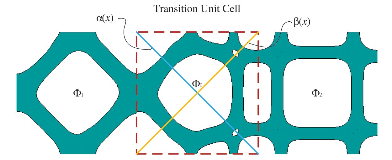
Figure 4: Interpolated transition unit cells with LSF Φ0
With the above algorithm, an interpolation unit cell can be obtained easily to transit the non-uniform unit cells. But when the two unit cells are greatly different in shape, the interpolation unit cell may vary sharply from one side to another side. This variation tendency can lead to poor properties or difficult manufacturability since the homogenization theory is based on asymptotic expansion. Hence, more gradual transition unit cells should be interpolated to reduce the variation. According to the interpolation algorithm for one transition unit cell, more transition unit cell interpolation can be conducted with a similar method. For interpolating m unit cells, the LSF of the ith transition unit cell
For example, if there are 5 transition unit cells, their interpolated LSFs are
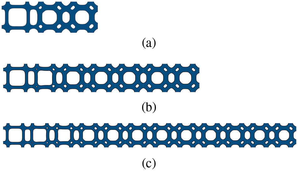
Figure 5: Multiple transition unit cells (a) 1 transition unit cell (b) 5 transition unit cells (c) 10 transition unit cells
2.2 Interpolation Algorithm of Morphing Microstructures
The method of transition microstructures can be employed simply to improve the connectivity problem for certain multi-scale topology optimization, such as the sandwich structure. When microstructures have a few different types, it can provide enough space to interpolate the transition unit cells by replacing the original unit cells. But for some complex multi-scale topology optimization, microstructures vary gradually along directions, which makes every adjacent unit cell different. So, there is no space to interpolate the transition unit cells. In this situation, non-uniform unit cells need to morph to adapt to the adjacent microstructure with connectivity.
Based on the algorithm of transition unit cells, the LSF
The interpolation method is based on the method in Eq. (4) to make the adjacent unit cells connect smoothly without transition unit cells. To morph the unit cells with the intermediate unit cell, the LSF of the original unit cell can be hybridized with the LSF of the intermediate unit cell obtained by Eq. (7).
where
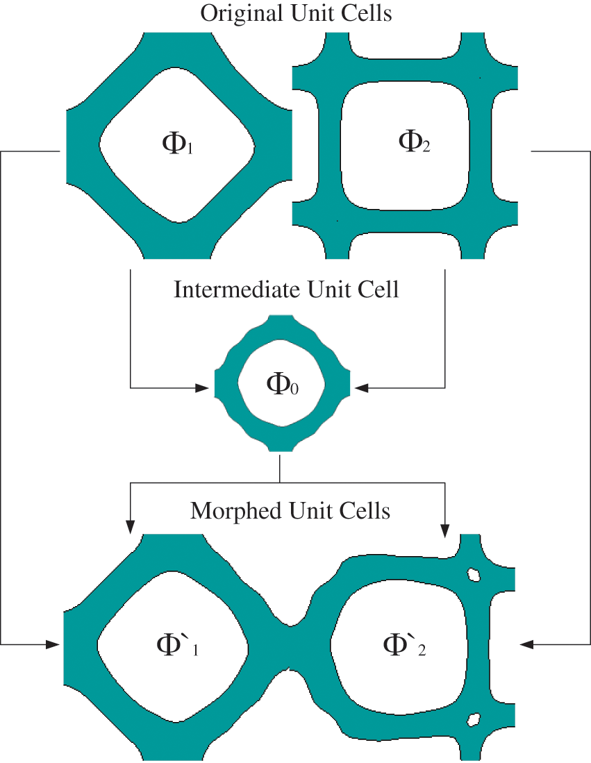
Figure 6: Morphed unit cells with intermediate unit cell
With the algorithm in Eqs. (8) and (9), the original unit cells could morph into new unit cells with features of each other. The interpolated morphed unit cell has both its own and the adjacent unit cells’ contour features, which creates a smooth connectivity between them. However, if the adjacent two unit cells are greatly different in shape, the new microstructure may morph tremendously from the original one, which would deviate from the optimal result. To eliminate the over-transformation in the non-connect region, the hybrid sections need to be near the connecting region and keep the central sections as original as possible. To realize this target, the foregoing linearly hybrid method should be updated to a nonlinear method. When interpolating the morphed unit cell, more proportion of the original microstructure is employed in the non-connect region, which has nonlinear weighting coefficients compared to Eqs. (4) and (5).
where n > 1 is a nonlinear coefficient to realize nonlinear weighting interpolation. With the above algorithm, the morphed unit cells in Fig. 6 can be updated to new morphed unit cells, which have less transformation in non-connect regions to diminish the effectiveness of the transformation.
This section introduces a new multi-scale topology optimization framework for graded cellular structures that utilizes the interpolation method of morphing microstructures, as discussed in Chapter 2. In contrast to the conventional method of multi-scale topology optimization, which involves designing macrostructures and microstructures separately using the homogenization method. By adopting the interpolation method for morphing microstructures after conventional topology optimization iterations, it is possible to morph graded cellular structures into connectable microstructures in a single direction.
The topology optimization of macrostructures can be implemented by the SIMP method. SIMP stands for Solid Isotropic Material with Penalization. It is a mathematical optimization method used in topology optimization, a process that seeks to determine the optimal material layout within a given design space, subject to certain structural and performance constraints. In the SIMP method, the material density is penalized to ensure that the optimized design is not too porous, and the penalization factor is gradually reduced during the optimization process to allow for the creation of more complex and intricate designs. The SIMP method has been widely used in various fields, including aerospace, automotive, and civil engineering, to design lightweight and efficient structures.
The topology optimization of microstructures can be implemented by the level-set method in Chapter 2.
The whole optimization procedure can be implemented by the following steps:
Step 1: Initialize the finite element (FE) model and define the parameters such as density (ρ), volume fraction, and elastic modulus (E*).
Step 2: Carry out topology optimization of macrostructures by density method and obtain the distribution of materials and displacement matrix of FE. Calculate the strain energy (ε*) as the objective function. Then calculate the sensitivity of variables and constraints.
Step 3: Carry out topology optimization of microstructures by level set method and update the LSFs of microstructures by displacement matrix obtained in step 2. Calculate the homogenous elastic tensor stiffness matrix of microstructures. Calculate the sensitivity of objective functions and constraints and update the coefficients of RBFs.
Step 4: Repeat steps 2 and 3 until objective functions converge.
Step 5: As shown in Fig. 7, morph every adjacent two microstructures by the algorithm in Eqs. (8) and (9) to obtain new connected microstructures gradually. Except for the microstructure on the boundary, every microstructure morphs with the left adjacent microstructure together first, then morphs with the right adjacent microstructure together, which creates a connected FGM finally.
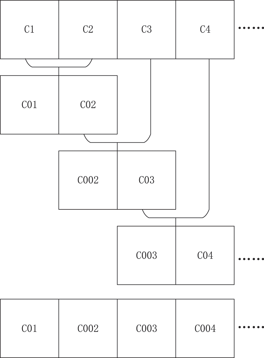
Figure 7: Hybrid stages of graded cellular structures
The interpolation morphing algorithm is implemented after conventional multi-scale topology optimization, so the method can fit general topology optimization cases through LSM and get proper connectivity between adjacent unit cells. The method can be independent of a major optimization process, which makes the algorithm commonly used.
In this section, we present a few numerical examples to show the implementation and result of the HLSM and the interpolation morphing algorithm described in Section 2.2. All of the microstructures are generated by PLSM and discretized into finite elements for calculating the elasticity matrix and displacement matrix. The base material of microstructures has Young’s modulus E0 = 910 and Poisson’s ratio μ = 0.3.
In Example 1, we select 2D microstructures with maximum bulk and shear modulus with different volume fractions (i.e., ρMI = 0.35, 0.4, 0.45, 0.5, 0.55, 0.6, 0.65, 0.7, 0.75, 0.8) to demonstrate the advantage and characteristic of the HLSM and Example 2 for 3D cases. In Example 3, a two-scale topology optimization of Layered Beam is implemented by HLSM to show the effectiveness and application of the HLSM in multi-scale topology optimization.
4.1 Example 1: 2D FGM with the Variation in Bulk and Shear Modulus
In this example, for a given series of 2D unit cells with maximum bulk modulus or shear modulus, the objective is to hybrid them which has volume fractions ranging from 0.35 to 0.8. The 2D FGM is divided into 10 unit cells and each cell has 30 × 30 4-node quadrilateral elements. The nonlinear coefficient in Eqs. (10) and (11) is selected as n = 4 to generate a nonlinear hybrid of unit cells.
Bulk modulus and shear modulus are two important mechanical properties of materials that describe how they respond to different types of stress. Bulk modulus is a measure of a material’s resistance to compression under uniform pressure. It is the ratio of the change in pressure to the fractional change in volume, and it describes how easy or difficult it is to compress a material. Materials with high bulk modulus are difficult to compress, while those with low bulk modulus are easily compressed. Shear modulus, on the other hand, is a measure of a material’s resistance to deformation when subjected to shear stress. It is the ratio of the shear stress to the shear strain, and it describes how a material responds to forces that cause it to deform in a parallel direction. Materials with high shear modulus are stiff and hard to deform, while those with low shear modulus are soft and easy to deform. Both bulk modulus and shear modulus are important for understanding the mechanical properties of materials, and they are commonly used in engineering and materials science applications.
In the 2D cases, the maximization of material bulk modulus corresponds to the minimization of
and the maximization of material shear modulus corresponds to the minimization of
where the
When the volume fraction increases from the left to the right, the hybrid macrostructure is shown in Fig. 8. In the conventional method, the boundaries of adjacent unit cells may be irregular for their different topologies. After morphing interpolation of unit cells, the boundaries of adjacent unit cells are smooth and connectable. Moreover, the non-connect region of the unit cell keeps its original to diminish the effect of the morphing procedure. It demonstrates that the interpolation algorithm of HLSM can improve the connectivity of graded 2D microstructures effectively and simply.
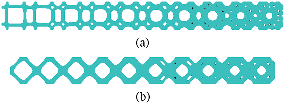
Figure 8: Optimized 2D FGM with volume fractions ranging from 0.35 to 0.8 (a) maximum bulk modulus (b) maximum shear modulus
Fig. 9 compares the bulk and shear modulus of unit cells before and after deformation to illustrate the effect of the interpolation algorithm and HLSM. According to the finite element analysis results, the morphed microstructures exhibit stiffness tensor properties that are similar to the original microstructures. This indicates that the proposed method can optimize the microstructures while preserving their original properties and properly connecting adjacent unit cells.
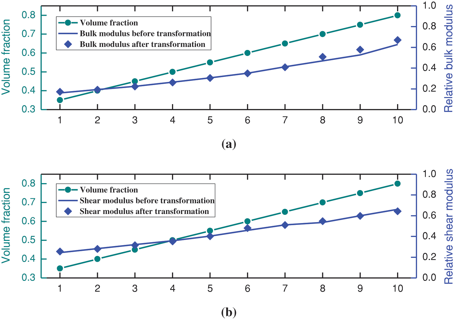
Figure 9: Comparison of properties before and after transformation (a) maximum bulk modulus (b) maximum shear modulus
4.2 Example 2: 3D FGM with the Variation in Bulk and Shear Modulus
In this example, for a given series of 3D unit cells with maximum bulk modulus or shear modulus, the objective is to hybrid them which has volume fractions ranging from 0.35 to 0.8. The 3D FGM is divided into 10 unit cells and each cell has 20 × 20 8-node cubic elements. The nonlinear coefficient in Eqs. (10) and (11) is selected as n = 4 to generate a nonlinear hybrid of unit cells.
In the 3D cases, the maximization of material bulk modulus corresponds to the minimization of
and the maximization of material shear modulus corresponds to the minimization of
When the volume fraction increases from the left to the right, the hybrid macrostructure is shown in Fig. 10. In 3D cases, the algorithm can also improve the connectivity of adjacent unit cells. The boundaries perform smoothly and properly after the post-processing. It demonstrates that the HLSM and interpolation algorithm is fit for 3D FGM design similar to 2D FGM, which can keep the properties of microstructures original and optimized as well as connect adjacent unit cells properly.
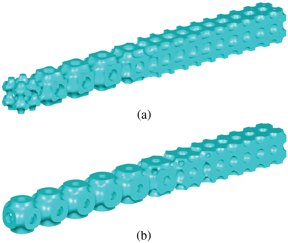
Figure 10: Optimized 3D FGM with volume fractions ranging from 0.35 to 0.8 (a) maximum bulk modulus (b) maximum shear modulus
The bulk and shear modulus of 3D unit cells before and after deformation are also compared in Fig. 11 to show the effect of the interpolation algorithm and HLSM. From the calculation results by finite element analysis, it can be seen that the morphed 3D microstructures also have approximate properties of stiffness tensor to the original 3D microstructures. It demonstrates the proposed method can keep the properties of 3D microstructures original and optimized like 2D cases.
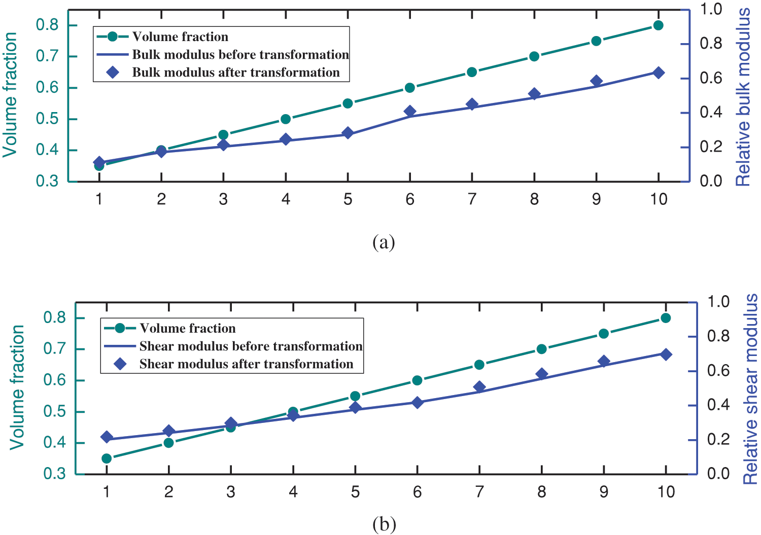
Figure 11: Comparison of properties before and after transformation (a) maximum bulk modulus (b) maximum shear modulus
4.3 Example 3: Two-Scale Topology Optimization of Layered Beam
In this example, we present a two-scale topology optimization of a layered beam. Fig. 12 shows a cantilever beam with loads of F = 100 applied on the end. The macro design domain is 60 × 30, which is discretized into 60 × 30 4-node quadrilateral elements. Hence, the dimension of each unit cell is 1 × 1. The objective function is to obtain the minimum mean compliance of the macrostructure under the volume fraction constrained to 0.6. The layered structure is used to solve the problem, which has the same microstructure in one layer and varies along the height direction.
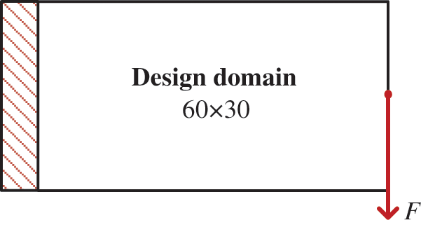
Figure 12: Design domain of the layered cantilever beam
The topology optimization result of the macro-scale is shown in Fig. 13a. Compared to the conventional SIMP method, the layered beam has a simpler structure, which makes it more feasible to fabricate the structure with microstructures. With the framework of multi-scale topology optimization in Chapter 3, the microstructures are optimized in Fig. 13b. It can be seen that the adjacent unit cells are not connected properly due to the independent calculation process.
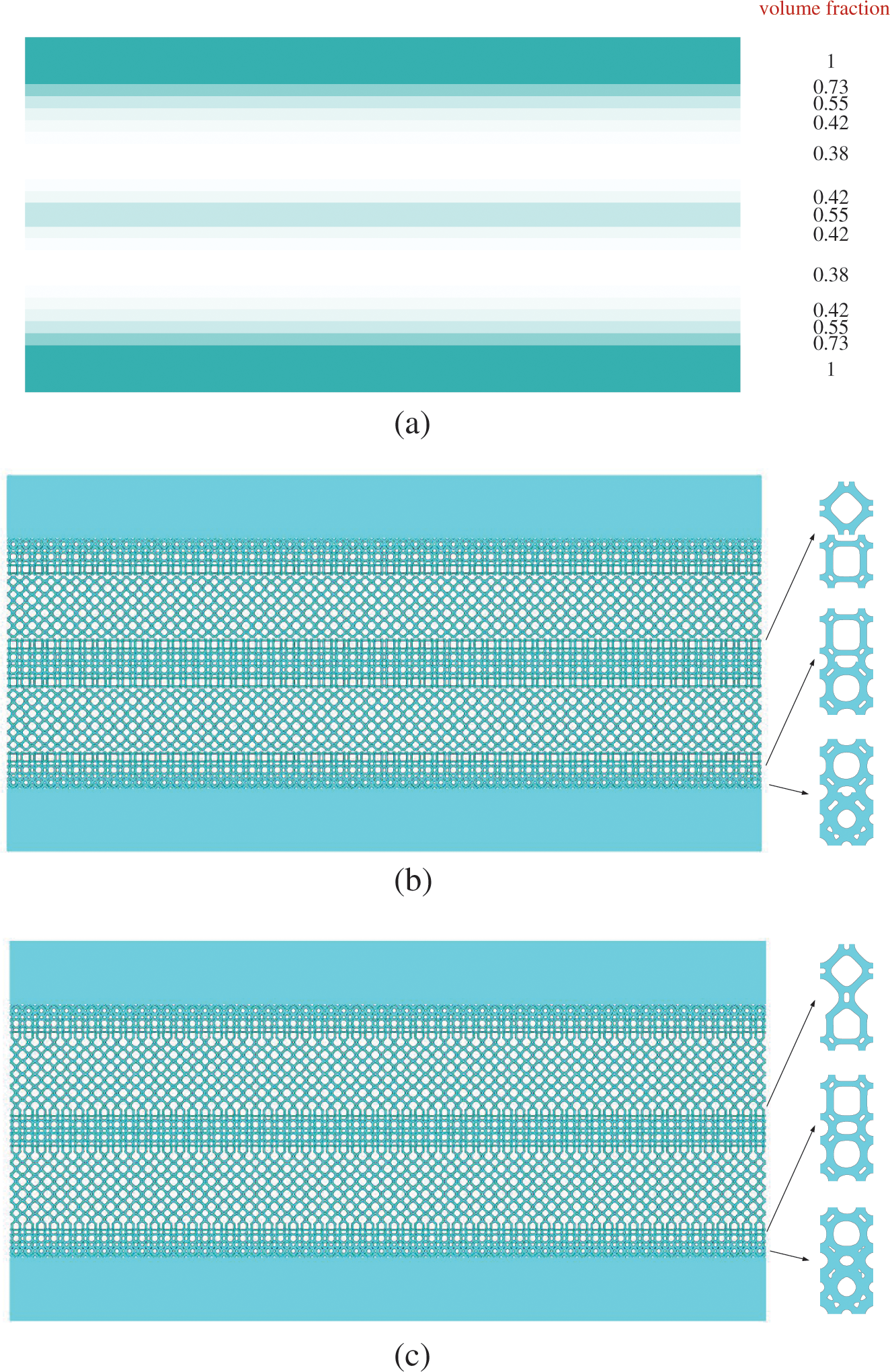
Figure 13: Two-scale topology optimization of layered beam (a) macro-scale topology optimization (b) micro-scale topology optimization without interpolation algorithm (c) micro-scale topology optimization with an interpolation algorithm
After post-processing with the interpolation algorithm of morphing microstructures, the structure is shown in Fig. 13c. Adjacent different unit cells create smooth connectivity with the post-process. It demonstrates that the HLSM and interpolation algorithm can fit the multi-scale topology optimization and solve the connectivity problem in certain cases.
A Multi-volume constraint approach to diverse form designs from topology optimization
A hybrid level set method (HLSM) is proposed to enhance connectivity between adjacent non-uniform microstructures. The method is presented as a post-processing step that can be easily embedded in a multi-scale topology optimization framework using LSM. The proposed interpolation algorithm generates transition microstructures using the LSFs of the original microstructures. The transition microstructure contains features from the adjacent microstructures that enable appropriate and smooth connections. To reduce excess transition microstructure, the interpolation algorithm can morph the original microstructures directly based on the transition microstructure. The microstructures obtained by LSM in multi-scale topology optimization have been observed to effectively transform into connectable structures, while simultaneously maintaining optimal properties in both 2D and 3D dimensions.
In this study, it was found that the morphed microstructure may be discontinuous in certain local regions due to significant differences in the original LSFs. One potential solution to this issue could be to adjust the nonlinear weighting coefficient in 2.2. However, it is planned to investigate a common and robust method to address this problem in future work.
Acknowledgement: The authors would like to express their gratitude to the editors and reviewers for their thorough review and valuable recommendations.
Funding Statement: This research was supported by the National Key Research and Development Program of China (Grant Number 2021YFB1714600), the National Natural Science Foundation of China (Grant Number 52075195), and the Fundamental Research Funds for the Central Universities, China through Program No. 2172019kfyXJJS078.
Author Contributions: The authors confirm contribution to the paper as follows: Study conception and design: Yan Dong; picture drawing: Kang Zhao; analysis of results: Yan Dong, Kang Zhao, Hao Li; draft manuscript preparation: Yan Dong, Kang Zhao, Hao Li, Liang Gao. All authors reviewed the results and approved the final version of the manuscript.
Availability of Data and Materials: Not applicable.
Conflicts of Interest: The authors declare that they have no conflicts of interest to report regarding the present study.
References
1. M. P. Bendsøe and N. Kikuchi, “Generating optimal topologies in structural design using a homogenization method,” Comput. Methods Appl. Mech. Eng., vol. 71, no. 2, pp. 197–224, Nov. 1988. doi: 10.1016/0045-7825(88)90086-2. [Google Scholar] [CrossRef]
2. D. Lukkassen, L. E. Persson, and P. Wall, “Some engineering and mathematical aspects on the homogenization method,” Compos. Eng., vol. 5, no. 5, pp. 519–531, Jan. 1995. doi: 10.1016/0961-9526(95)00025-I. [Google Scholar] [CrossRef]
3. M. P. Bendsøe, “Optimal shape design as a material distribution problem,” Struct. Optim., vol. 1, no. 4, pp. 193–202, Dec. 1989. doi: 10.1007/BF01650949. [Google Scholar] [CrossRef]
4. H. P. Mlejnek, “Some aspects of the genesis of structures,” Struct. Optim., vol. 5, no. 1–2, pp. 64–69, Mar. 1992. doi: 10.1007/BF01744697. [Google Scholar] [CrossRef]
5. M. Zhou and G. I. N. Rozvany, “The COC algorithm, Part II: Topological, geometrical and generalized shape optimization,” Comput. Methods Appl. Mech. Eng., vol. 89, no. 1–3, pp. 309–336, Aug. 1991. doi: 10.1016/0045-7825(91)90046-9. [Google Scholar] [CrossRef]
6. G. Allaire, F. Jouve, and A. M. Toader, “A level-set method for shape optimization,” C. R. Math., vol. 334, no. 12, pp. 1125–1130, Jan. 2002. doi: 10.1016/S1631-073X(02)02412-3. [Google Scholar] [CrossRef]
7. G. Allaire, F. Jouve, and A. M. Toader, “Structural optimization using sensitivity analysis and a level-set method,” J. Comput. Phys., vol. 194, no. 1, pp. 363–393, Feb. 2004. doi: 10.1016/j.jcp.2003.09.032. [Google Scholar] [CrossRef]
8. S. Osher and J. A. Sethian, “Fronts propagating with curvature-dependent speed: Algorithms based on Hamilton-Jacobi formulations,” J. Comput. Phys., vol. 79, no. 1, pp. 12–49, Nov. 1988. doi: 10.1016/0021-9991(88)90002-2. [Google Scholar] [CrossRef]
9. M. Y. Wang, X. Wang, and D. Guo, “A level set method for structural topology optimization,” Comput. Methods Appl. Mech. Eng., vol. 192, no. 1–2, pp. 227–246, Jan. 2003. doi: 10.1016/S0045-7825(02)00559-5. [Google Scholar] [CrossRef]
10. Y. M. Xie and G. P. Steven, “A simple evolutionary procedure for structural optimization,” Comput. Struct., vol. 49, no. 5, pp. 885–896, Dec. 1993. doi: 10.1016/0045-7949(93)90035-C. [Google Scholar] [CrossRef]
11. V. Young, O. M. Querin, G. P. Steven, and Y. M. Xie, “3D and multiple load case bi-directional evolutionary structural optimization (BESO),” Struct. Optim., vol. 18, no. 2–3, pp. 183–192, Oct. 1999. doi: 10.1007/BF01195993. [Google Scholar] [CrossRef]
12. X. Guo, W. Zhang, and W. Zhong, “Doing topology optimization explicitly and geometrically—a new moving morphable components based framework,” J. Appl. Mech., vol. 81, no. 8, pp. 197, Jun. 2014. doi: 10.1115/1.4027609. [Google Scholar] [CrossRef]
13. W. Xu, C. Liu, Y. L. Guo, Z. L. Du, W. S. Zhang and X. Guo, “Graded infill lattice structures design based on the moving morphable component method and partitioned coordinate mapping technique,” Compos. Struct., vol. 326, pp. 117613, Oct. 2023. doi: 10.1016/j.compstruct.2023.117613. [Google Scholar] [CrossRef]
14. N. P. van Dijk, K. Maute, M. Langelaar, and F. van Keulen, “Level-set methods for structural topology optimization: A review,” Struct. Multidiscip. Optim., vol. 48, no. 3, pp. 437–472, Mar. 2013. doi: 10.1007/s00158-013-0912-y. [Google Scholar] [CrossRef]
15. S. Wang and M. Y. Wang, “Radial basis functions and level set method for structural topology optimization,” Int. J. Numer. Methods Eng., vol. 65, no. 12, pp. 2060–2090, Oct. 2005. doi: 10.1002/nme.1536. [Google Scholar] [CrossRef]
16. S. Y. Wang, K. M. Lim, B. C. Khoo, and M. Y. Wang, “An extended level set method for shape and topology optimization,” J. Comput. Phys., vol. 221, no. 1, pp. 395–421, Jan. 2007. doi: 10.1016/j.jcp.2006.06.029. [Google Scholar] [CrossRef]
17. Y. Z. Wu, J. G. Fang, C. Wu, C. Y. Li, G. Y. Sun and Q. Li, “Additively manufactured materials and structures: A state-of-the-art review on their mechanical characteristics and energy absorption,” Int. J. Mech. Sci., vol. 246, no. 9–12, pp. 108102, May 2023. doi: 10.1016/j.ijmecsci.2023.108102. [Google Scholar] [CrossRef]
18. J. H. Zhu, H. Zhou, C. Wang, L. Zhou, S. Q. Yuan and W. H. Zhang, “A review of topology optimization for additive manufacturing: Status and challenges,” Chin. J. Aeronaut., vol. 34, no. 1, pp. 91–110, Jan. 2021. doi: 10.1016/j.cja.2020.09.020. [Google Scholar] [CrossRef]
19. R. Lakes, “Materials with structural hierarchy,” Nature, vol. 361, no. 6412, pp. 511–515, Feb. 1993. doi: 10.1038/361511a0. [Google Scholar] [CrossRef]
20. J. Wu, O. Sigmund, and J. P. Groen, “Topology optimization of multi-scale structures: A review,” Struct. Multidiscip. Optim., vol. 63, no. 3, pp. 1455–1480, Mar. 2021. doi: 10.1007/s00158-021-02881-8. [Google Scholar] [CrossRef]
21. H. Li, L. Gao, H. Li, and H. Tong, “Spatial-varying multi-phase infill design using density-based topology optimization,” Comput. Methods Appl. Mech. Eng., vol. 372, pp. 113354, Dec. 2020. doi: 10.1016/j.cma.2020.113354. [Google Scholar] [CrossRef]
22. X. Yan, Y. Xiong, D. W. Bao, Y. M. Xie, and X. Peng, “A Multi-volume constraint approach to diverse form designs from topology optimization,” Eng. Struct., vol. 279, no. 9–10, pp. 115525, Mar. 2023. doi: 10.1016/j.engstruct.2022.115525. [Google Scholar] [CrossRef]
23. P. Liu, Z. Kang, and Y. J. Luo, “Two-scale concurrent topology optimization of lattice structures with connectable microstructures,” Addit. Manuf., vol. 36, no. 6190, pp. 101427, Dec. 2020. doi: 10.1016/j.addma.2020.101427. [Google Scholar] [CrossRef]
24. C. Wang, X. J. Gu, J. H. Zhu, H. Zhou, S. Y. Li and W. H. Zhang, “Concurrent design of hierarchical structures with three-dimensional parameterized lattice microstructures for additive manufacturing,” Struct. Multidiscip. Optim., vol. 61, no. 3, pp. 869–894, Mar. 2020. doi: 10.1007/s00158-019-02408-2. [Google Scholar] [CrossRef]
25. X. N. Su, W. J. Chen, and S. T. Liu, “Multi-scale topology optimization for minimizing structural compliance of cellular composites with connectable graded microstructures,” Struct. Multidiscip. Optim., vol. 64, no. 4, pp. 2609–2625, Oct. 2021. doi: 10.1007/s00158-021-03014-x. [Google Scholar] [CrossRef]
26. M. Zhao, X. W. Li, D. Z. Zhang, and W. Zhai, “TPMS-based interpenetrating lattice structures: Design, mechanical properties and multiscale optimization,” Int. J. Mech. Sci., vol. 244, no. 45, pp. 108092, Apr. 2023. doi: 10.1016/j.ijmecsci.2022.108092. [Google Scholar] [CrossRef]
27. H. L. Zhou, D. Z. Zhang, N. H. He, and M. Zhao, “Topology optimization of multi-morphology composite lattice structure with anisotropy properties,” Compos. Struct., vol. 321, no. 3, pp. 117294, Oct. 2023. doi: 10.1016/j.compstruct.2023.117294. [Google Scholar] [CrossRef]
28. P. G. Coelho and H. C. Rodrigues, “Hierarchical topology optimization addressing material design constraints and application to sandwich-type structures,” Struct. Multidiscip. Optim., vol. 52, no. 1, pp. 91–104, Oct. 2015. doi: 10.1007/s00158-014-1220-x. [Google Scholar] [CrossRef]
29. C. Wang, J. H. Zhu, W. H. Zhang, S. Y. Li, and J. Kong, “Concurrent topology optimization design of structures and non-uniform parameterized lattice microstructures,” Struct. Multidiscip. Optim., vol. 58, no. 1, pp. 35–50, Jun. 2018. doi: 10.1007/s00158-018-2009-0. [Google Scholar] [CrossRef]
30. A. Panesar, M. Abdi, D. Hickman, and I. Ashcroft, “Strategies for functionally graded lattice structures derived using topology optimisation for Additive Manufacturing,” Addit. Manuf., vol. 19, no. 2121, pp. 81–94, Jan. 2018. doi: 10.1016/j.addma.2017.11.008. [Google Scholar] [CrossRef]
31. E. Garner, H. M. A. Kolken, C. C. L. Wang, A. A. Zadpoor, and J. Wu, “Compatibility in microstructural optimization for additive manufacturing,” Addit. Manuf., vol. 26, no. 1, pp. 65–75, Mar. 2019. doi: 10.1016/j.addma.2018.12.007. [Google Scholar] [CrossRef]
32. S. Watts, W. Arrighi, J. Kudo, D. A. Tortorelli, and D. A. White, “Simple, accurate surrogate models of the elastic response of three-dimensional open truss micro-architectures with applications to multiscale topology design,” Struct. Multidiscip. Optim., vol. 60, no. 5, pp. 1887–1920, May 2019. doi: 10.1007/s00158-019-02297-5. [Google Scholar] [CrossRef]
33. Z. Wu, L. Xia, S. Wang, and T. Shi, “Topology optimization of hierarchical lattice structures with substructuring,” Comput. Methods Appl. Mech. Eng., vol. 345, no. 2, pp. 602–617, Mar. 2019. doi: 10.1016/j.cma.2018.11.003. [Google Scholar] [CrossRef]
34. R. Murphy, C. Imediegwu, R. Hewson, and M. Santer, “Multiscale structural optimization with concurrent coupling between scales,” Struct. Multidiscip. Optim., vol. 63, no. 4, pp. 1721–1741, Jan. 2021. doi: 10.1007/s00158-020-02773-3. [Google Scholar] [CrossRef]
35. Y. Zhou, L. Gao, and H. Li, “Graded infill design within free-form surfaces by conformal mapping,” Int. J. Mech. Sci., vol. 224, pp. 107307, Jun. 2022. doi: 10.1016/j.ijmecsci.2022.107307. [Google Scholar] [CrossRef]
36. Y. Zhou, L. Gao, and H. Li, “Topology optimization design of graded infills for 3D curved volume by a conformal sweeping method,” Comput. Methods Appl. Mech. Eng., vol. 412, pp. 116009, Jul. 2023. doi: 10.1016/j.cma.2023.116009. [Google Scholar] [CrossRef]
37. S. H. Liang, L. Gao, Y. F. Zheng, and H. Li, “A transitional connection method for the design of functionally graded cellular materials,” Appl. Sci., vol. 10, no. 21, pp. 7449, Nov. 2020. doi: 10.3390/app10217449. [Google Scholar] [CrossRef]
38. S. Zhou and Q. Li, “Design of graded two-phase microstructures for tailored elasticity gradients,” J. Mater. Sci., vol. 43, no. 15, pp. 5157–5167, Aug. 2008. doi: 10.1007/s10853-008-2722-y. [Google Scholar] [CrossRef]
39. S. Zhou and Q. Li, “Microstructural design of connective base cells for functionally graded materials,” Mater. Lett., vol. 62, no. 24, pp. 4022–4024, Sep. 2008. doi: 10.1016/j.matlet.2008.05.058. [Google Scholar] [CrossRef]
40. A. Radman, X. Huang, and Y. M. Xie, “Topology optimization of functionally graded cellular materials,” J. Mater. Sci., vol. 48, no. 4, pp. 1503–1510, Sep. 2012. doi: 10.1007/s10853-012-6905-1. [Google Scholar] [CrossRef]
41. A. Radman, X. Huang, and Y. M. Xie, “Maximizing stiffness of functionally graded materials with prescribed variation of thermal conductivity,” Comput. Mater. Sci., vol. 82, pp. 457–463, Feb. 2014. doi: 10.1016/j.commatsci.2013.10.024. [Google Scholar] [CrossRef]
42. O. Sigmund, “A 99 line topology optimization code written in Matlab,” Struct. Multidiscip. Optim., vol. 21, no. 2, pp. 120–127, Apr. 2001. doi: 10.1007/s001580050176. [Google Scholar] [CrossRef]
43. A. D. Cramer, V. J. Challis, and A. P. Roberts, “Microstructure interpolation for macroscopic design,” Struct. Multidiscip. Optim., vol. 53, no. 3, pp. 489–500, Oct. 2015. doi: 10.1007/s00158-015-1344-7. [Google Scholar] [CrossRef]
44. Y. Wang, F. Chen, and M. Y. Wang, “Concurrent design with connectable graded microstructures,” Comput. Methods Appl. Mech. Eng., vol. 317, no. 6202, pp. 84–101, Apr. 2017. doi: 10.1016/j.cma.2016.12.007. [Google Scholar] [CrossRef]
45. Y. Wang, L. Zhang, S. Daynes, H. Zhang, S. Feih and M. Y. Wang, “Design of graded lattice structure with optimized mesostructures for additive manufacturing,” Mater. Des., vol. 142, no. 9, pp. 114–123, Mar. 2018. doi: 10.1016/j.matdes.2018.01.011. [Google Scholar] [CrossRef]
46. Z. Du, X. Y. Zhou, R. Picelli, and H. A. Kim, “Connecting microstructures for multiscale topology optimization with connectivity index constraints,” J. Mech. Des., vol. 140, no. 11, pp. 031001, Oct. 2018. doi: 10.1115/1.4041176. [Google Scholar] [CrossRef]
47. X. Y. Zhou, Z. Du, and H. A. Kim, “A level set shape metamorphosis with mechanical constraints for geometrically graded microstructures,” Struct. Multidiscip. Optim., vol. 60, no. 1, pp. 1–16, May 2019. doi: 10.1007/s00158-019-02293-9. [Google Scholar] [CrossRef]
48. I. Maskery, A. O. Aremu, L. Parry, R. D. Wildman, C. J. Tuck and I. A. Ashcroft, “Effective design and simulation of surface-based lattice structures featuring volume fraction and cell type grading,” Mater. Des., vol. 160, pp. 106–107, Dec. 2018. doi: 10.1016/j.matdes.2018.09.007. [Google Scholar] [CrossRef]
49. J. Deng, C. B. W. Pedersen, and W. Chen, “Connected morphable components-based multiscale topology optimization,” Front. Mech. Eng., vol. 14, no. 2, pp. 129–140, Jan. 2019. doi: 10.1007/s11465-019-0532-3. [Google Scholar] [CrossRef]
50. E. D. Sanders, A. Pereira, and G. H. Paulino, “Optimal and continuous multilattice embedding,” Sci. Adv., vol. 7, no. 16, pp. 296, Apr. 2021. doi: 10.1126/sciadv.abf4838 [Google Scholar] [PubMed] [CrossRef]
51. H. Zong, H. Liu, Q. Ma, Y. Tian, M. Zhou and M. Y. Wang, “VCUT level set method for topology optimization of functionally graded cellular structures,” Comput. Methods Appl. Mech. Eng., vol. 354, no. 1838, pp. 487–505, Sep. 2019. doi: 10.1016/j.cma.2019.05.029. [Google Scholar] [CrossRef]
52. H. Liu, Y. T. Qi, L. X. Chen, Y. W. Li, and W. L. Xiao, “An efficient data-driven optimization framework for designing graded cellular structures,” Appl. Math. Model., vol. 125, no. 7646, pp. 574–598, Jan. 2024. doi: 10.1016/j.apm.2023.10.020. [Google Scholar] [CrossRef]
53. H. Liu, H. Zong, T. Shi, and Q. Xia, “M-VCUT level set method for optimizing cellular structures,” Comput. Methods Appl. Mech. Eng., vol. 367, no. 8, pp. 113154, Aug. 2020. doi: 10.1016/j.cma.2020.113154. [Google Scholar] [CrossRef]
54. S. M. T. Zobaer and A. Sutradhar, “An energy-based method for interface connectivity of incompatible microstructures through parametric modeling,” Comput. Methods Appl. Mech. Eng., vol. 370, no. 4, pp. 113278, Oct. 2020. doi: 10.1016/j.cma.2020.113278. [Google Scholar] [CrossRef]
55. D. Patel, D. Bielecki, R. Rai, and G. Dargush, “Improving connectivity and accelerating multiscale topology optimization using deep neural network techniques,” Struct. Multidiscip. Optim., vol. 65, no. 4, pp. 363, Mar. 2022. doi: 10.1007/s00158-022-03223-y. [Google Scholar] [CrossRef]
56. C. Zhang, S. Xu, J. Liu, and Y. Ma, “Comprehensive clustering-based topology optimization for connectable multi-scale additive manufacturing structures,” Addit. Manuf., vol. 54, pp. 102786, Jun. 2022. doi: 10.1016/j.addma.2022.102786. [Google Scholar] [CrossRef]
57. Y. Kim, P. C. H. Nguyen, H. Kim, and Y. Choi, “Multi-morphology cellular structure design with smooth transition of geometry and homogenized mechanical properties between adjacent cells,” Mater. Des., vol. 218, no. 6086, pp. 110727, Jun. 2022. doi: 10.1016/j.matdes.2022.110727. [Google Scholar] [CrossRef]
58. B. S. Liu, X. M. Wang, Z. Zhuang, and Y. A. Cui, “Dynamic concurrent topology optimization and design for layer-wise graded structures,” Compos. Struct., vol. 319, no. 14, pp. 117190, Sep. 2023. doi: 10.1016/j.compstruct.2023.117190. [Google Scholar] [CrossRef]
Cite This Article
 Copyright © 2024 The Author(s). Published by Tech Science Press.
This work is licensed under a Creative Commons Attribution 4.0 International License , which permits unrestricted use, distribution, and reproduction in any medium, provided the original work is properly cited.
 Downloads
 Citation Tools