
 Submit a Paper
 Propose a Special lssue
 Open Access
ARTICLE

Mechanical Properties of Copper with Dendritic Silver Inclusions: Insights from Molecular Dynamics Simulations
Departamento de Física, Facultad de Ciencias Naturales, Matemática y del Medio Ambiente, Universidad Tecnológica Metropolitana, Las Palmeras 3360, Ñuñoa, Santiago, 7800003, Chile
* Corresponding Author: Nicolás Amigo. Email:
Computers, Materials & Continua 2024, 81(3), 3665-3678. https://doi.org/10.32604/cmc.2024.059895
Received 19 October 2024; Accepted 26 November 2024; Issue published 19 December 2024
 View Full Text
 Download PDF
Abstract
This study explores the mechanical behavior of single-crystal copper with silver inclusions, focusing on the effects of dendritic and spherical geometries using molecular dynamics simulations. Uniaxial tensile tests reveal that dendritic inclusions lead to an earlier onset of plasticity due to the presence of high-strain regions at the complex inclusion/matrix interfaces, whereas spherical inclusions exhibit delayed plasticity associated with their symmetric geometry and homogeneous strain distribution. During the plastic regime, the dislocation density is primarily influenced by the volume fraction of silver inclusions rather than their shape, with spherical inclusions showing the highest densities due to their larger volume and higher silver content. Stacking faults, quantified via hexagonal closed-packed atom populations, are strongly correlated with dislocation activity but exhibit transient behavior, indicating that many faults are swept out or transformed during deformation. This transfient effect is observed in all cases, independently of the inclusion size. These findings highlight the complex interplay between inclusion geometry, dislocation activity, and stacking fault evolution in shaping the mechanical properties of copper. The study underscores the need to account for inclusion morphology and defect dynamics when designing advanced copper-based materials and suggests further investigations into the role of dendrite orientation and distribution to enhance material performance in engineering applications.Keywords
Secondary metallic phases in metal matrices significantly influence mechanical properties such as strength, hardness, and ductility. These phases, formed through alloying or thermal treatments, can enhance performance depending on their composition, size, and distribution [1–4]. Dendritic structures, which commonly form during solidification, also play a crucial role in determining mechanical behavior, impacting strength, hardness, and ductility based on factors such as arm spacing, distribution, and volume fraction [5–9]. Understanding these interactions is essential for optimizing the mechanical properties of metals in advanced engineering applications, including nuclear reactors, turbines, electrocatalysis, and the development of lighter materials [10–13].
Molecular dynamics (MD) simulations are a valuable tool for exploring the effects of inclusions on the mechanical behavior of materials. Various studies can be found in the literature. Some examples include investigations into plastic deformation mechanisms in Cu-Ag core-shell nanowires [14], the enhancement of tensile strength by Zn species in Al samples [15], interaction mechanisms in Fe samples with P impurities and nano oxides [16], and P-induced embrittlement in W grain boundaries [17], among many others [18–22]. Most current research has focused on dispersed impurities, laminates, or spherical precipitates. However, more complex structures, such as dendrites, have rarely been addressed. A recent study systematically explored the effect of crystalline dendrites on the plastic response of CuZr metallic glasses [23]. Despite this novel approach, each sample considered only a single planar dendrite, leaving the effects of three-dimensional structures and their interactions unaddressed. Several efforts have been made to simulate dendritic structures using phase-field models informed by data from MD simulations. Examples include the study of titanium solidification and crystal-melt interfacial properties [24], crystallization kinetics and crystal growth mechanisms in titanium [25], and interfacial energy anisotropy in Al-Cu systems [26], among others. These works have provided valuable insights into the thermodynamics and kinetics of dendritic growth, but no studies have yet explored the effects of dendrites on mechanical behavior.
In this work, three-dimensional dendritic structures are constructed and simulated using molecular dynamics (MD) simulations to evaluate their effect on the mechanical properties of Cu. Artificial intelligence tools are used to generate the dendrites, with Ag chosen as the atomic species for the dendritic structures. Uniaxial tensile tests are performed to assess the mechanical performance of Cu samples containing a single dendrite. For comparison, Cu samples containing a single spherical inclusion are also considered. Mechanical properties, plasticity, and atomic-level descriptions are provided to elucidate the influence of these dendritic structures.
2.1 Construction of Dendritic Structures
Constructing three-dimensional dendritic structures is a complex task, as experimental data typically consists of two-dimensional images. Therefore, it is necessary to develop methodologies that can generate three-dimensional structures from two-dimensional data. In recent years, various artificial intelligence (AI) tools have been developed to accomplish this, many of which are freely available online. In this work, the AI-based 3D model generator MESHY [27] was employed. The software utilizes computer vision to generate three-dimensional representations from two-dimensional objects. Two different images of dendritic structures were used as input data, selected from the work of Kim et al. [28], where the authors used phase-field simulations to produce growth morphologies. The process for transforming the images into three-dimensional representations is outlined in Fig. 1. In the first step, the two-dimensional image was uploaded to Meshy. In the second step, Meshy generated a three-dimensional representation, producing an stereolithography (STL) file. In the third step, a bulk atomic configuration with dimensions of
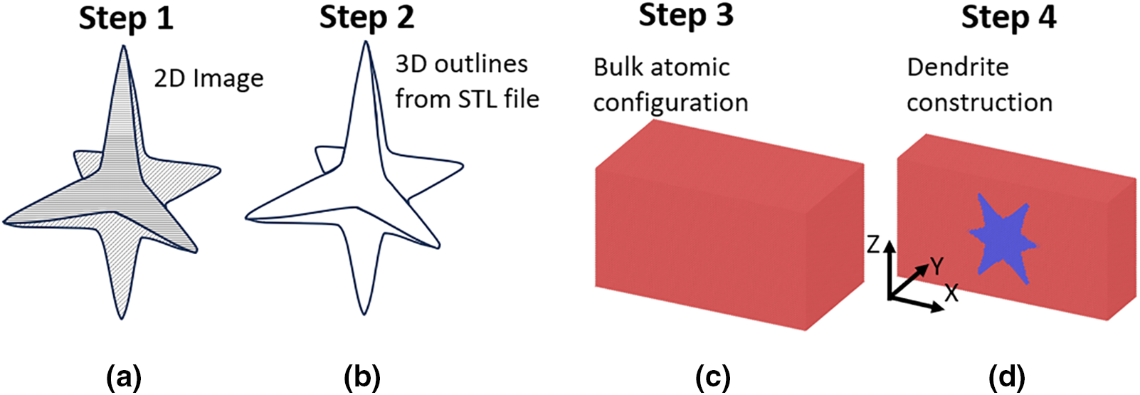
Figure 1: Pipeline for the construction of dendritic structures. (a) Selection of two-dimensional image, (b) three-dimensional representation produced by Meshy, (c) construction of the atomic configuration, and (d) introduction of the dendritic structure in the atomic configuration
2.2 Preparation of the Samples
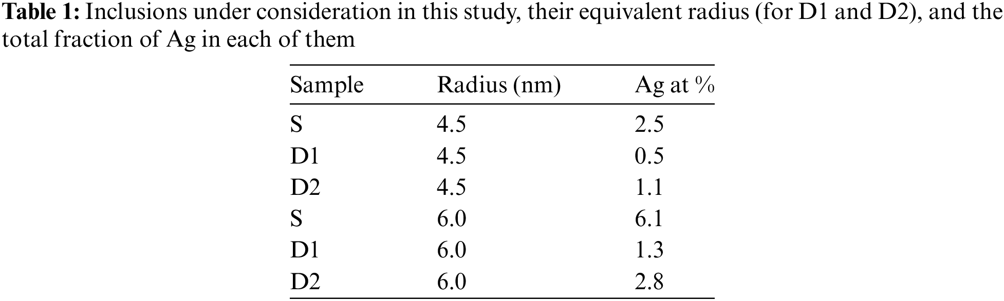
The obtained configurations, consisting of a dendritic structure embedded in a matrix, were used to study the mechanical behavior of single-crystal Cu with Ag inclusions. The dendritic structures were assigned to Ag atoms, while the matrix was assigned to Cu atoms. In addition to the two dendrites, a spherical inclusion with a radius of R was also considered. The two dendrites were scaled to have similar equivalent radii, resulting in six different Cu/Ag inclusion configurations: two dendrites and one spherical inclusion with a radius of 4.5 nm, and two dendrites and one spherical inclusion with a radius of 6.0 nm. The configuration with the spherical inclusion is referred to as the S sample hereafter, while the configurations with dendritic structures are referred to as D1 and D2 samples. The three inclusions for
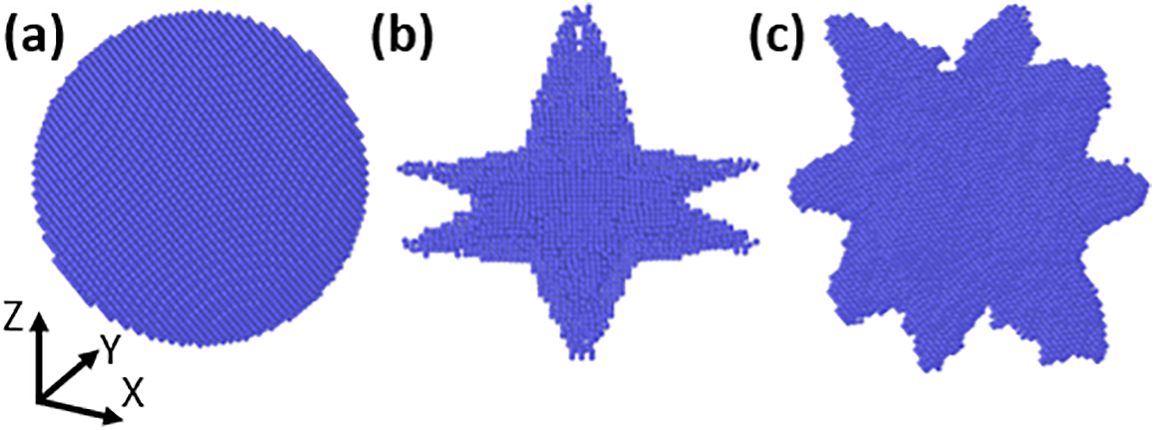
Figure 2: Three-dimensional representation of the three defects with radius
Uniaxial tensile tests were conducted by scaling the atomic positions in the
All simulations were conducted using the Large-scale Atomic/Molecular Massively Parallel Simulator (LAMMPS) [34,35]. Atomic interactions were modeled with the potential developed by Williams et al., based on the embedded atom method (EAM) framework [36]. The equations were integrated with a timestep of 1 fs.
When studying metals at the atomic scale, whether they contain grain boundaries, voids, vacancies, or inclusions, it is essential to conduct annealing to relax the interfaces. During this procedure, it is expected that dislocation nucleation, twinning, grain size reduction, or small atomic rearrangements occur [37–40]. To address this matter, the dislocations nucleated after the annealing process were examined. Fig. 3 shows the dislocations identified by DXA in the 6.0 nm spherical and dendritic inclusions. Blue lines correspond to perfect dislocations, while atoms in green, white, and red correspond to face-centered cubic (FCC), hexagonal closed-packed (HCP), and other (unidentified) structures, respectively, as indicated by CNA. In the case of the spherical inclusion, perfect dislocations are homogeneously distributed due to the high symmetry of the spherical geometry. Most of the atoms remain in the FCC structure, with some exhibiting unidentified structures, typically found at the interfaces of two different phases due to atomic mismatch [41–44]. In contrast, for the dendritic inclusions, dislocations are heterogeneously distributed, with a high fraction of Ag atoms showing unidentified structures. Moreover, the presence of Ag atoms exhibiting HCP structure is more prominent in both D1 and D2 compared to the spherical inclusion. The dislocation density after annealing in each configuration was calculated, resulting in the values shown in Fig. 4, where
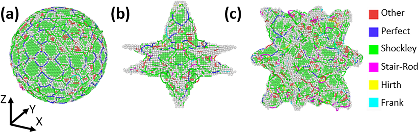
Figure 3: Dislocations identified by DXA in the 6.0 nm (a) inclusion, (b) D1, and (c) D2 structures. Dislocation lines are colored according to the type indicated in the legend, while atoms in green, white, and red correspond to FCC, HCP, and Other structure, respectively
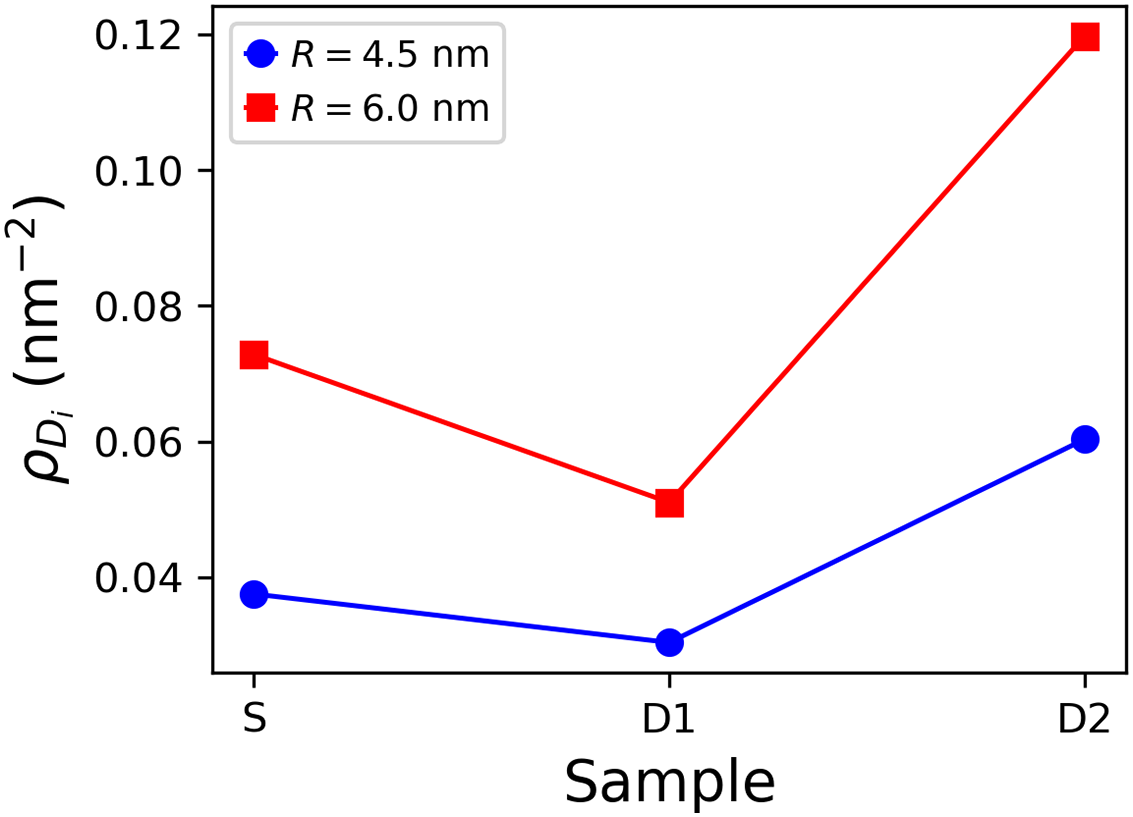
Figure 4: Dislocation density in each configuration after annealing
Mechanical characterization was performed using uniaxial tensile tests, resulting in the stress-strain curves shown in Fig. 5. In the 4.5 nm samples, the elastic regime is very similar across the three samples. However, yielding occurs earlier in the D2 sample, followed by D1, and then by the S sample. A sawtooth-like behavior is observed, typical of single-crystal metals, due to dislocation nucleation [45,46]. In the case of the 6.0 nm samples, the elastic regime remains similar up to 0.02 strain. However, slight differences arise as the samples approach the onset of yielding, suggesting that the increased Ag content (ranging from 1.3% to 6.1%) affects the onset of plasticity. Additionally, the S samples exhibit the highest yield stress. Nevertheless, the plastic regime indicated by the stress-strain curves does not show significant differences. Stress-strain curves for single-crystal Cu with Ag inclusions, in both spherical and dendritic forms, can inform targeted applications. If dendritic inclusions show earlier onset of plasticity, they could be beneficial in load-bearing applications requiring adaptability under fluctuating loads, such as connectors or structural components exposed to impacts. In the case of spherical inclusions, they contribute to higher yield strength, which may enhance wear resistance in precision parts like electrical contacts or microscale mechanical systems.
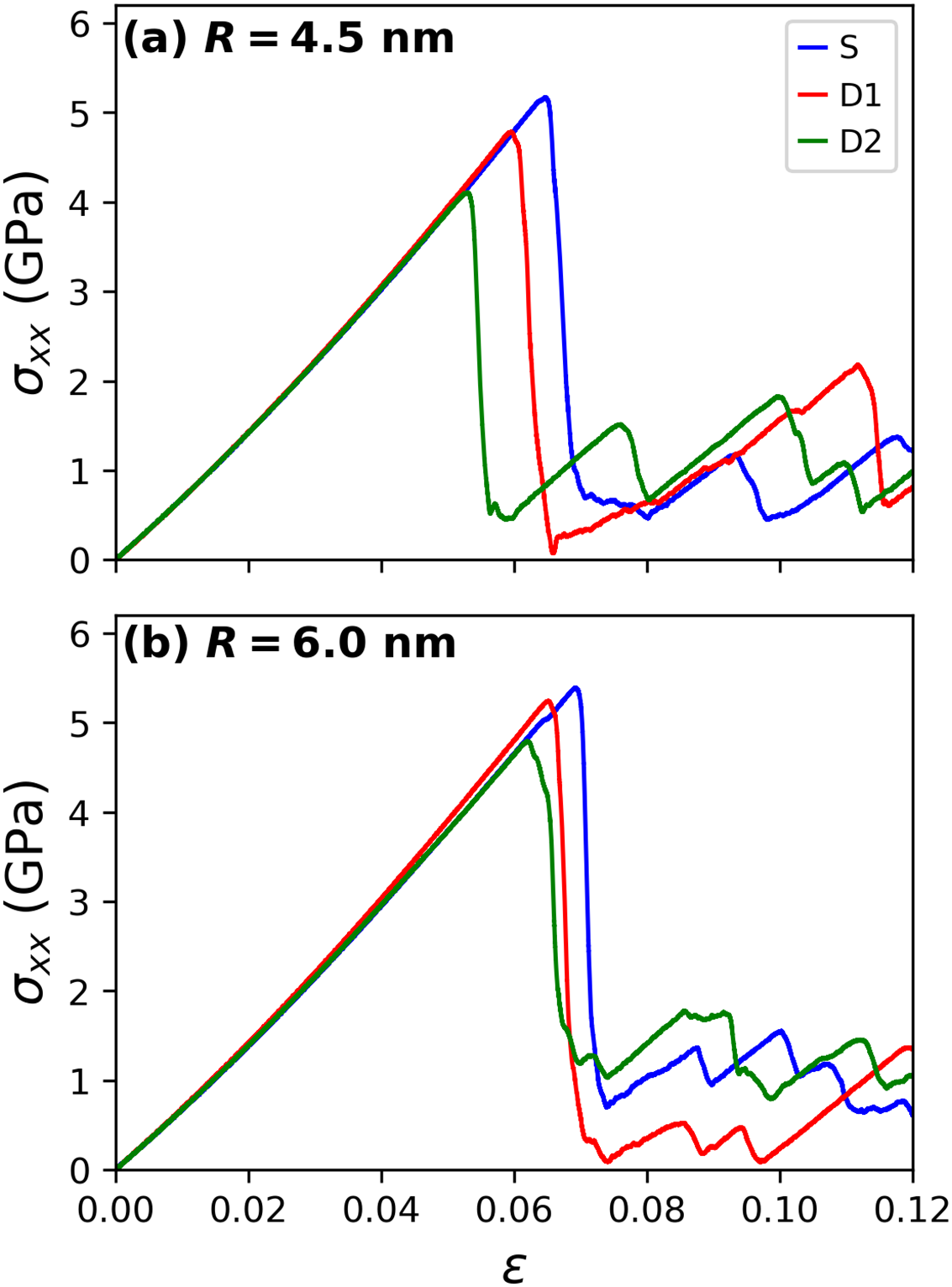
Figure 5: Stress-strain curves from the uniaxial tensile tests for the (a) 4.5 nm and (b) 6.0 nm radius inclusions
Quantification of the Young’s modulus (E) and yield stress (
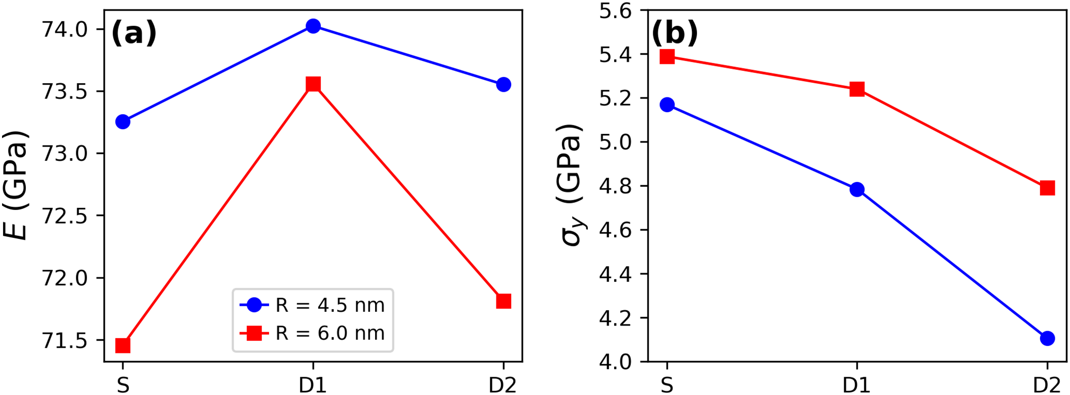
Figure 6: (a) Young’s modulus and (b) yield stress (
Qualitative descriptions of the deformation behavior were conducted using DXA and CNA. Fig. 7a–c shows the onset of plasticity for the 6.0 nm configurations, where lines correspond to dislocations identified by DXA, and atoms are colored according to CNA. FCC atoms were removed for visualization purposes. In the case of the S sample, plasticity initiates from the surface of the spherical inclusion, characterized by a leading partial dislocation (green lines) and a stacking fault (red atoms). For the dendritic inclusions, plasticity begins earlier and more abruptly, with large partial dislocations and stacking faults. As observed from the strain fields in Fig. 7d–f, the higher symmetry of the spherical inclusion induces a homogeneous strain distribution prior to the onset of plasticity. In contrast, the complex shapes of the dendrites involve regions with both high and negligible strains, ultimately leading to the abrupt onset of plasticity. Characterizing the geometric effects of the dendrites on the plastic response is a challenging task due to their three-dimensional nature and is beyond the scope of the current study.
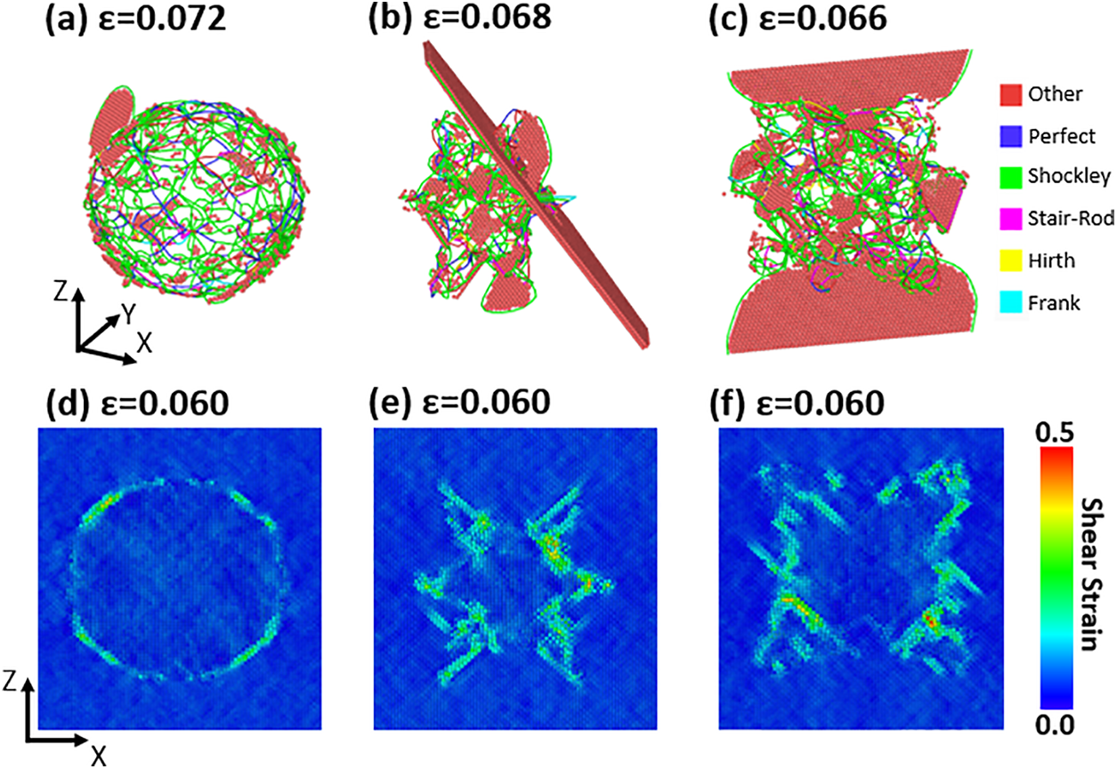
Figure 7: Onset of plasticity of the (a) S, (b) D1, (c) D2 samples, where lines correspond to dislocations (see the legend) and red atoms to stacking faults. Strain fields of the (d) S, (e) D1, (f) D2 samples just before the onset of plasticity
Plasticity was quantified by means of dislocation density (
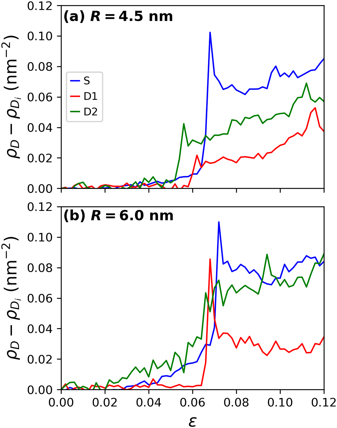
Figure 8: Dislocation density (
In addition to partial dislocation nucleation, stacking faults are also formed during the plastic regime, as previously observed in Fig. 7. Although quantifying the number of stacking faults is challenging, insights can be gained by calculating the number of HCP atoms associated with these planar defects, albeit with certain limitations. For instance, depending on the atomic arrangement, HCP atoms in a monolayer can represent twin boundaries [50–52]. The variations in the population of HCP atoms are shown in Fig. 9. The pattern is very similar to that of the dislocation densities; specifically, the D1 and D2 samples exhibit an earlier increase in the populations of HCP atoms. However, for the 4.5 nm cases, the S samples show a strong peak followed by a drastic decrease, while the opposite behavior is observed in the D1 and D2 samples. In contrast, for the 6.0 nm cases, all samples exhibit sharp peaks during the onset of plasticity, which then decrease to semi-stable populations. It is important to note that not all HCP atoms correspond to stacking faults; some may represent isolated atoms or noisy atoms identified by CNA. Moreover, stacking faults are formed by leading partial dislocations and can be eliminated by trailing partial dislocations. Therefore, not all stacking faults persist during deformation; many can disappear throughout the process [53,54].
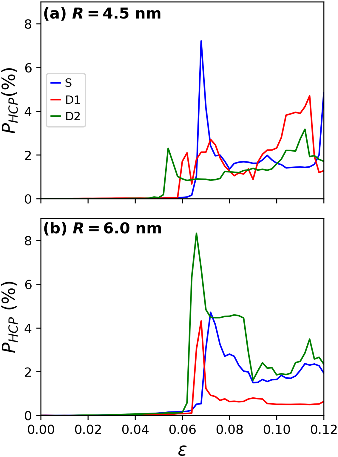
Figure 9: Populations of HCP atoms for the (a) 4.5 nm and (b) 6.0 nm radius inclusions during the tensile tests
To further examine plastic activity, dislocations in the 6.0 nm samples at various strain levels were analyzed, as illustrated in Fig. 10. In all three cases, dislocations propagate from the inclusion/matrix interface to the surrounding material. As noted earlier, most dislocations are Shockley partials, with some traces of Stair-Rod dislocations. Comparing the three configurations, the S and D2 samples exhibit a substantial number of line defects, reflecting the higher dislocation densities shown in Fig. 8. This high density results in entangled dislocations, which can eventually lead to work hardening, consistent with the higher stress observed in the stress-strain curves for the S and D2 samples relative to the D1 case in Fig. 5b.
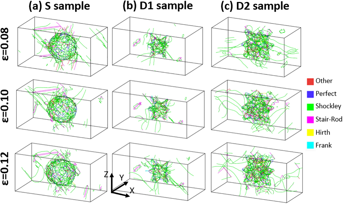
Figure 10: Dislocations in the 6.0 nm radius (a) S, (b) D1, and (c) D2 samples at different strains. Dislocations are colored according to the type indicated in the legend. Atoms were removed for visualization purposes
Dislocation densities and stacking faults play a critical role in the mechanical performance of metals in real-world applications. High dislocation densities generally increase strength through mechanisms like work hardening, where dislocations obstruct their movement, enhancing the resistance to further deformation. This is valuable in applications requiring durability under repeated loading, such as in structural beams or aerospace components. Stacking faults also impact mechanical properties by modifying the slip behavior, thereby affecting ductility and toughness. In materials with controlled stacking fault densities, these faults might enhance energy absorption and resistance to fracture, making them ideal for demanding applications in construction and automotive industries where resilience under impact or high loads is essential. Overall, managing dislocation densities and stacking faults provides a powerful approach to optimizing strength and toughness for specific engineering applications.
In this study, we investigated the mechanical properties of copper with silver inclusions, specifically focusing on the influence of dendritic structures using molecular dynamics simulations. Our findings demonstrate that the complex morphology of dendrites affects the onset of plasticity and the subsequent dislocation behavior. The dislocation density results indicate a direct relationship between the shape of the inclusions and the nucleation of dislocations, with dendritic structures facilitating earlier plastic deformation compared to spherical inclusions. Notably, the largest dislocation activity was observed in samples with higher volume fractions of inclusions, highlighting the importance of not only the inclusion geometry, but also its volume fraction in determining the mechanical response of copper.
Furthermore, the quantification of stacking faults through HCP atom analysis provided additional insights into the deformation mechanisms at play. While HCP populations were shown to correlate with dislocation densities, the behavior of stacking faults revealed that not all defects persist during deformation. However, it is important to note that HCP atoms are not necessarily a reliable representation of stacking faults. This study underscores the necessity of considering both inclusion shape and defect dynamics when designing copper-based materials for advanced engineering applications.
Future work could explore the effects of varying dendrite orientations, branching patterns, and spatial distributions on mechanical performance, as these factors may impact dislocation mobility and deformation pathways. Experimental studies using SEM imaging could validate simulation findings by visualizing dendrite morphology and dislocation structures, providing direct insights into the microstructural behavior under stress. Additionally, multi-scale simulations or experimental analyses could further examine the thermal stability of these inclusions and their influence on fatigue resistance, broadening our understanding of how dendritic structures can enhance the durability and performance of copper-based alloys in engineering applications.
Acknowledgement: Powered@NLHPC: This research was partially supported by the supercomputing infrastructure of the NLHPC (ECM-02).
Funding Statement: Project supported by the Competition for Research Regular Projects, year 2023, code LPR23-05, Universidad Tecnológica Metropolitana (NA).
Availability of Data and Materials: The data that support the findings of this study are available from the corresponding author, upon reasonable request.
Ethics Approval: This study did not involve any human or animal subjects, and therefore, ethical approval was not required.
Conflicts of Interest: The author declares no conflicts of interest to report regarding the present study.
References
1. D. Bishop, J. Cahoon, M. Chaturvedi, G. Kipouros, and W. Caley, “On enhancing the mechanical properties of aluminum p/m alloys,” Mater. Sci. Eng.: A, vol. 290, no. 1, pp. 16–24, 2000. doi: 10.1016/S0921-5093(00)00957-6. [Google Scholar] [CrossRef]
2. L. Falat, A. Schneider, G. Sauthoff, and G. Frommeyer, “Mechanical properties of Fe–Al–M–C (M=Ti, V, Nb, Ta) alloys with strengthening carbides and laves phase,” Intermetallics, vol. 13, no. 12, pp. 1256–1262, 2005. doi: 10.1016/j.intermet.2004.05.010. [Google Scholar] [CrossRef]
3. E. Zhang, W. He, H. Du, and K. Yang, “Microstructure, mechanical properties and corrosion properties of Mg–Zn–Y alloys with low Zn content,” Mater. Sci. Eng.: A, vol. 488, no. 1, pp. 102–111, 2008. doi: 10.1016/j.msea.2007.10.056. [Google Scholar] [CrossRef]
4. C. -L. Chen, A. Richter, and R. Thomson, “Investigation of mechanical properties of intermetallic phases in multi-component Al-Si alloys using hot-stage nanoindentation,” Intermetallics, vol. 18, no. 4, pp. 499–508, 2010. doi: 10.1016/j.intermet.2009.09.013. [Google Scholar] [CrossRef]
5. W. R. Osório and A. Garcia, “Modeling dendritic structure and mechanical properties of Zn-Al alloys as a function of solidification conditions,” Mater. Sci. Eng.: A, vol. 325, no. 1, pp. 103–111, 2002. doi: 10.1016/S0921-5093(01)01455-1. [Google Scholar] [CrossRef]
6. G. A. Santos, C. de Moura Neto, W. R. Osório, and A. Garcia, “Design of mechanical properties of a Zn27Al alloy based on microstructure dendritic array spacing,” Mater. Des., vol. 28, no. 9, pp. 2425–2430, 2007. doi: 10.1016/j.matdes.2006.09.009. [Google Scholar] [CrossRef]
7. M. V. Canté, J. E. Spinelli, N. Cheung, and A. Garcia, “The correlation between dendritic microstructure and mechanical properties of directionally solidified hypoeutectic Al-Ni alloys,” Met. Mater. Int., vol. 16, no. 1, pp. 39–49, Feb. 2010. doi: 10.1007/s12540-010-0039-2. [Google Scholar] [CrossRef]
8. Y. Ruan, A. Mohajerani, and M. Dao, “Microstructural and mechanical-property manipulation through rapid dendrite growth and undercooling in an Fe-based multinary alloy,” Sci. Rep., vol. 6, no. 1, Aug. 2016, Art. no. 31684. doi: 10.1038/srep31684. [Google Scholar] [PubMed] [CrossRef]
9. B. A. Potekhin, A. S. Khristolyubov, and A. Y. Zhilyakov, “Development of composite bronzes reinforced by steel dendrites,” Russ. J. Nonferr. Met., vol. 59, no. 5, pp. 527–532, Sep. 2018. doi: 10.3103/S1067821218050140. [Google Scholar] [CrossRef]
10. D. C. Chrzan, J. W. Morris, Y. N. Osetsky, R. E. Stoller, and S. J. Zinkle, “What is the limit of nanoparticle strengthening?” MRS Bull., vol. 34, no. 3, pp. 173–177, Mar. 2009. doi: 10.1557/mrs2009.48. [Google Scholar] [CrossRef]
11. P. Yvon and F. Carré, “Structural materials challenges for advanced reactor systems,” J. Nucl. Mater., vol. 385, no. 2, pp. 217–222, 2009. doi: 10.1016/j.jnucmat.2008.11.026. [Google Scholar] [CrossRef]
12. S. -S. Li et al., “Development and applications of aluminum alloys for aerospace industry,” J. Mater. Res. Technol., vol. 27, pp. 944–983, 2023. doi: 10.1016/j.jmrt.2023.09.274. [Google Scholar] [CrossRef]
13. P. Zhang et al., “Alloy as advanced catalysts for electrocatalysis: From materials design to applications,” Chin. Chem. Lett., vol. 35, no. 6, 2024, Art. no. 109073. doi: 10.1016/j.cclet.2023.109073. [Google Scholar] [CrossRef]
14. P. T. Li, Y. Q. Yang, X. Luo, N. Jin, G. Liu and Y. Gao, “Structural evolution of copper-silver bimetallic nanowires with core-shell structure revealed by molecular dynamics simulations,” Comput. Mater. Sci., vol. 137, pp. 289–296, 2017. doi: 10.1016/j.commatsci.2017.05.040. [Google Scholar] [CrossRef]
15. H. W. Jang, S. E. Lee, and J. -W. Hong, “Molecular dynamics evaluation of the effects of zinc on the mechanical properties of aluminum alloys,” Comput. Mater. Sci., vol. 159, pp. 66–72, 2019. doi: 10.1016/j.commatsci.2018.11.050. [Google Scholar] [CrossRef]
16. M. M. Azeem, D. Yun, and M. Zubair, “Atomic insights on interaction mechanism of dislocation with void/impurity/precipitates in BCC Iron, ser,” in Int. Conf. Nuclear Eng., Aug. 2021, V002T05A015. doi: 10.1115/ICONE28-65197. [Google Scholar] [CrossRef]
17. P. A. Olsson, P. Hiremath, and S. Melin, “Atomistic investigation of the impact of phosphorus impurities on the tungsten grain boundary decohesion,” Comput. Mater. Sci., vol. 219, 2023, Art. no. 112017. doi: 10.1016/j.commatsci.2023.112017. [Google Scholar] [CrossRef]
18. Y. Dou, X. He, D. Wang, W. Shi, L. Jia and W. Yang, “The study of nanosized Cu-Mn precipitates contribution to hardening in body centered cubic Fe matrix,” J. Nucl. Eng. Radiat. Sci., vol. 4, no. 4, Sep. 2018, Art. no. 041007. doi: 10.1115/1.4039969. [Google Scholar] [CrossRef]
19. X. Wu et al., “Softening effects due to reorientations of Cu precipitates in
20. S. A. Ibrahim, Q. Wang, Y. Zhang, M. Ado, G. D. Chung and M. M. Azeem, “Molecular dynamics simulation of strengthening dependence on precipitate Cr composition in Fe-15at.%Cr alloy,” Micron, vol. 131, 2020, Art. no. 102823. doi: 10.1016/j.micron.2020.102823. [Google Scholar] [PubMed] [CrossRef]
21. H. Noori et al., “A systematic molecular dynamics investigation on the graphene polymer nanocomposites for bulletproofing,” Comput., Mater. Contin., vol. 65, no. 3, pp. 2009–2032, 2020. [Google Scholar]
22. N. Amigo, “Mechanical characterization of nanocrystalline Cu-Ag alloys subjected to shear deformation,” Mol. Simul., vol. 50, no. 16, pp. 1–9, 2024. doi: 10.1080/08927022.2024.2409197. [Google Scholar] [CrossRef]
23. J. Xi, F. Yang, X. Zhang, and H. Zhou, “Effect of geometry of crystalline dendrite on the uniaxial tension behavior of metallic glass matrix composites based on molecular dynamics simulations,” Mater. Today Commun., vol. 37, 2023, Art. no. 107229. doi: 10.1016/j.mtcomm.2023.107229. [Google Scholar] [CrossRef]
24. S. Kavousi, B. R. Novak, M. A. Zaeem, and D. Moldovan, “Combined molecular dynamics and phase field simulation investigations of crystal-melt interfacial properties and dendritic solidification of highly undercooled titanium,” Comput. Mater. Sci., vol. 163, no. 6, pp. 218–229, 2019. doi: 10.1016/j.commatsci.2019.03.024. [Google Scholar] [CrossRef]
25. S. Kavousi, A. Gates, L. Jin, and M. Asle Zaeem, “A temperature-dependent atomistic-informed phase-field model to study dendritic growth,” J. Cryst. Growth, vol. 579, no. 4, 2022, Art. no. 126461. doi: 10.1016/j.jcrysgro.2021.126461. [Google Scholar] [CrossRef]
26. A. Swamy, D. Dolce, and P. Choudhury, “Atomistic insight into dendrite growth orientation transition in Al-Cu alloy,” Mater. Today Commun., vol. 37, 2023, Art. no, 107404. doi: 10.1016/j.mtcomm.2023.107404. [Google Scholar] [CrossRef]
27. E. Y. Hu, “Meshy-free 3D AI model generator—meshy.ai,” 2014. Accessed: Oct. 17, 2024. [Online]. Available: https://www.meshy.ai/ [Google Scholar]
28. G. Kim, T. Takaki, Y. Shibuta, S. Sakane, K. Matsuura and M. Ohno, “A parametric study of morphology selection in equiaxed dendritic solidification,” Comput. Mater. Sci., vol. 162, no. 2, pp. 76–81, 2019. doi: 10.1016/j.commatsci.2019.02.027. [Google Scholar] [CrossRef]
29. G. Guo, H. Wang, D. Bell, Y. Bi, and K. Greer, “KNN model-based approach in classification,” in On The Move to Meaningful Internet Systems 2003: CoopIS, DOA, and ODBASE, R. Meersman, Z. Tari, D. C. Schmidt, Eds. Berlin, Heidelberg: Springer Berlin Heidelberg, 2003, pp. 986–996. [Google Scholar]
30. A. Stukowski, V. V. Bulatov, and A. Arsenlis, “Automated identification and indexing of dislocations in crystal interfaces,” Model. Simul. Mater. Sci. Eng., vol. 20, no. 8, Oct. 2012, Art. no. 085007. doi: 10.1088/0965-0393/20/8/085007. [Google Scholar] [CrossRef]
31. J. D. Honeycutt and H. C. Andersen, “Molecular dynamics study of melting and freezing of small lennard-jones clusters,” J. Phys. Chem., vol. 91, no. 19, pp. 4950–4963, 1987. doi: 10.1021/j100303a014. [Google Scholar] [CrossRef]
32. D. Faken and H. Jónsson, “Systematic analysis of local atomic structure combined with 3D computer graphics,” Comput. Mater. Sci., vol. 2, no. 2, pp. 279–286, 1994. doi: 10.1016/0927-0256(94)90109-0. [Google Scholar] [CrossRef]
33. A. Stukowski, “Visualization and analysis of atomistic simulation data with OVITO-the open visualization tool,” Model. Simul. Mater. Sci. Eng., vol. 18, no. 1, 2010, Art. no. 015012. doi: 10.1088/0965-0393/18/1/015012. [Google Scholar] [CrossRef]
34. S. Plimpton, “Fast parallel algorithms for short-range molecular dynamics,” J. Comput. Phys., vol. 117, no. 1, pp. 1–19, 1995. [Google Scholar]
35. A. P. Thompson et al., “LAMMPS–A flexible simulation tool for particle-based materials modeling at the atomic, meso, and continuum scales,” Comp. Phys. Comm., vol. 271, 2022, Art. no. 108171. doi: 10.1016/j.cpc.2021.108171. [Google Scholar] [CrossRef]
36. P. L. Williams, Y. Mishin, and J. C. Hamilton, “An embedded-atom potential for the Cu-Ag system,” Model. Simul. Mater. Sci. Eng., vol. 14, no. 5, May 2006, Art. no. 817. doi: 10.1088/0965-0393/14/5/002. [Google Scholar] [CrossRef]
37. X. Tong, H. Zhang, and D. Y. Li, “Effect of annealing treatment on mechanical properties of nanocrystalline
38. V. Borovikov, M. I. Mendelev, and A. H. King, “Effects of grain boundary disorder on dislocation emission,” Mater. Lett., vol. 237, pp. 303–305, 2019. [Google Scholar]
39. H. Sun, S. Fu, C. Chen, Z. Wang, and C. V. Singh, “Kinetics of annealing-induced detwinning in chemical vapor deposited nickel,” Acta Mater., vol. 178, pp. 263–274, 2019. doi: 10.1016/j.actamat.2019.08.010. [Google Scholar] [CrossRef]
40. W. Yang, Y. X. Wu, and H. Gong, “Molecular dynamics simulations of the effects of annealing on the micro residual stress induced by vacancy defects in aluminum crystal,” J. Cryst. Growth, vol. 546, no. 3, 2020, Art. no. 125754. doi: 10.1016/j.jcrysgro.2020.125754. [Google Scholar] [CrossRef]
41. J. Zhou, R. Averback, and P. Bellon, “Stability and amorphization of Cu-Nb interfaces during severe plastic deformation: Molecular dynamics simulations of simple shear,” Acta Mater., vol. 73, pp. 116–127, 2014. doi: 10.1016/j.actamat.2014.03.055. [Google Scholar] [CrossRef]
42. X. Zhou and C. Chen, “Molecular dynamic simulations of the mechanical properties of crystalline/crystalline and crystalline/amorphous nanolayered pillars,” Comput. Mater. Sci., vol. 101, pp. 194–200, 2015. doi: 10.1016/j.commatsci.2015.01.033. [Google Scholar] [CrossRef]
43. S. Kumar, “Graphene engendered aluminium crystal growth and mechanical properties of its composite: An atomistic investigation,” Mater. Chem. Phys., vol. 208, no. 1, pp. 41–48, 2018. doi: 10.1016/j.matchemphys.2018.01.013. [Google Scholar] [CrossRef]
44. J. Li, Y. Huang, Y. Zhou, and F. Zhu, “Molecular dynamics study of compressive properties and atomistic behavior of boron nitride nanosheets reinforced in aluminum matrix composites,” JOM, vol. 74, no. 9, pp. 3518–3530, Sep. 2022. doi: 10.1007/s11837-022-05381-2. [Google Scholar] [CrossRef]
45. Y. Gao, H. Wang, J. Zhao, C. Sun, and F. Wang, “Anisotropic and temperature effects on mechanical properties of copper nanowires under tensile loading,” Comput. Mater. Sci., vol. 50, no. 10, pp. 3032–3037, 2011. doi: 10.1016/j.commatsci.2011.05.023. [Google Scholar] [CrossRef]
46. N. Amigo, G. Gutiérrez, and M. Ignat, “Atomistic simulation of single crystal copper nanowires under tensile stress: Influence of silver impurities in the emission of dislocations,” Comput. Mater. Sci., vol. 87, pp. 76–82, 2014. doi: 10.1016/j.commatsci.2014.02.014. [Google Scholar] [CrossRef]
47. Y. Mishin, M. J. Mehl, D. A. Papaconstantopoulos, A. F. Voter, and J. D. Kress, “Structural stability and lattice defects in copper: Ab initio, tight-binding, and embedded-atom calculations,” Phys. Rev. B, vol. 63, May 2001, Art. no. 224106. doi: 10.1103/PhysRevB.63.224106. [Google Scholar] [CrossRef]
48. S. S. Sarangi, “Study on youngs modulus of metallic nanowires using classical molecular dynamics simulations,” Mater. Today: Proc., vol. 41, pp. 413–415, 2021. [Google Scholar]
49. D. Chen, Y. Zhang, and S. Xu, “Solute-enhanced twin boundary migration in CuAg alloy,” J. Appl. Phys., vol. 135, no. 4, Jan. 2024, Art. no. 045104. doi: 10.1063/5.0176708. [Google Scholar] [CrossRef]
50. K. V. Reddy and S. Pal, “Influence of dislocations, twins, and stacking faults on the fracture behavior of nanocrystalline Ni nanowire under constant bending load: A molecular dynamics study,” J. Mol. Model., vol. 24, no. 10, 2018, Art. no. 277. doi: 10.1007/s00894-018-3813-6. [Google Scholar] [PubMed] [CrossRef]
51. J. Li, Y. Wang, D. Yan, and J. Li, “Effects of nanotwins and stacking faults on the mechanical properties of CrCoNi medium-entropy alloys,” J. Mater. Res. Technol., vol. 27, no. 8, pp. 3447–3458, 2023. doi: 10.1016/j.jmrt.2023.10.144. [Google Scholar] [CrossRef]
52. Z. Bai, T. Fu, H. Hu, W. Yu, and X. Peng, “Automated identification of stacking faults and twin boundaries in face-centered cubic crystal,” Comput. Mater. Sci., vol. 235, no. 23, 2024, Art. no. 112837. doi: 10.1016/j.commatsci.2024.112837. [Google Scholar] [CrossRef]
53. J. W. Wang, S. Narayanan, J. Y. Huang, Z. Zhang, T. Zhu and S. X. Mao, “Atomic-scale dynamic process of deformation-induced stacking fault tetrahedra in gold nanocrystals,” Nat. Commun., vol. 4, no. 1, 2013, Art. no. 2340. doi: 10.1038/ncomms3340. [Google Scholar] [PubMed] [CrossRef]
54. X. Kong et al., “Interface facilitated transformation of voids directly into stacking fault tetrahedra,” Acta Mater., vol. 188, pp. 623–634, 2020. doi: 10.1016/j.actamat.2020.02.044. [Google Scholar] [CrossRef]
Cite This Article
 Copyright © 2024 The Author(s). Published by Tech Science Press.
This work is licensed under a Creative Commons Attribution 4.0 International License , which permits unrestricted use, distribution, and reproduction in any medium, provided the original work is properly cited.
 Downloads
 Citation Tools