
 Submit a Paper
 Propose a Special lssue
 Open Access
ARTICLE
Microscopic Modeling and Failure Mechanism Study of Fiber Reinforced Composites Embedded with Optical Fibers
1 State Key Laboratory of Structural Analysis, Optimization and CAE Software for Industrial Equipment, School of Mechanics and Aerospace Engineering, Dalian University of Technology, Dalian, 116024, China
2 Liaoshen Industries Group Co., Ltd., Shenyang, 110045, China
3 School of Materials Science and Engineering, Dalian University of Technology, Dalian, 116024, China
4 School of Fiber Engineering and Equipment Technology, Jiangnan University, Wuxi, 214122, China
* Corresponding Author: Lei Yang. Email:
(This article belongs to the Special Issue: Computational Modeling of Mechanical Behavior of Advanced Materials)
Computers, Materials & Continua 2025, 84(1), 265-279. https://doi.org/10.32604/cmc.2025.065676
Received 19 March 2025; Accepted 29 April 2025; Issue published 09 June 2025
 View Full Text
 Download PDF
Abstract
Embedding optical fiber sensors into composite materials offers the advantage of real-time structural monitoring. However, there is an order-of-magnitude difference in diameter between optical fibers and reinforcing fibers, and the detailed mechanism of how embedded optical fibers affect the micromechanical behavior and damage failure processes within composite materials remains unclear. This paper presents a micromechanical simulation analysis of composite materials embedded with optical fibers. By constructing representative volume elements (RVEs) with randomly distributed reinforcing fibers, the optical fiber, the matrix, and the interface phase, the micromechanical behavior and damage evolution under transverse tensile and compressive loads are explored. The study finds that the presence of embedded optical fibers significantly influences the initiation and propagation of microscopic damage within the composites. Under transverse tension, the fiber-matrix interface cracks first, followed by plastic cracking in the matrix surrounding the fibers, forming micro-cracks. Eventually, these cracks connect with the debonded areas at the fiber-matrix interface to form a dominant crack that spans the entire model. Under transverse compression, plastic cracking first occurs in the resin surrounding the optical fibers, connecting with the interface debonding areas between the optical fibers and the matrix to form two parallel shear bands. Additionally, it is observed that the strength of the interface between the optical fiber and the matrix critically affects the simulation results. The simulated damage morphologies align closely with those observed using scanning electron microscopy (SEM). These findings offer theoretical insights that can inform the design and fabrication of smart composite materials with embedded optical fiber sensors for advanced structural health monitoring.Keywords
Under the multi-field coupling effects of extreme environments and complex loads, large equipment structures are highly susceptible to material property degradation at both macro and micro levels. This degradation can lead to a reduction in structural bearing capacity and pose significant safety risks [1]. Consequently, it is crucial to employ advanced sensors for synchronous health monitoring during the service life of these structures [2]. Optical fiber sensors have multiple advantages such as small size, light weight, electromagnetic interference resistance, and adaptability to harsh environments, which have been widely used in the field of structural health monitoring [3–7]. By embedding optical fiber sensors within a composite structure, we can create an intelligent composite structure capable of self-sensing strain and temperature. This capability significantly enhances the structure’s safety and reliability [8–12].
The common method of embedding optical fibers into composite materials involves placing the optical fibers between two layers of prepreg and curing them together [13]. However, since the diameter of a typical optical fiber (>100 μm) is more than an order of magnitude larger than that of the commonly used reinforcing fibers, this process may introduce defects within the material, potentially affecting the mechanical properties of the overall structure [14–17]. Therefore, it is crucial to study the impact of embedding optical fibers on the performance of composite structures, particularly at the microscopic scale.
Some scholars have conducted mechanical experiments on composite materials with embedded optical fibers. Etches and Fernando [18] found that embedded sensors have a certain impact on material properties under tension and compression fatigue loads. The study observed that sensor performance varied significantly with loading type—tensile loading caused sensor failure at 0.5% strain, while compressive loading allowed sensor operation until composite failure at 1.1% strain [19]. Hadzic et al. [20] embedded optical fibers with different densities and found that as the number and density of optical fibers increased, the tensile and compressive strengths of the material decreased more significantly. Abidin et al. [21] explored the impact of the material properties and thickness of the external coating of optical fibers on the mechanical properties of the structure. The results indicated that when using a polyimide coating, the structure’s Young’s modulus was greater compared to using an acrylate coating. Furthermore, as the coating thickness decreased, the difference in mechanical properties between structures with different coatings embedded became smaller. Shivakumar et al. [22,23] conducted tensile and compression experiments on laminates embedded with optical fibers using a tensile machine and observed the whole process of material fracture failure through a traveling microscope.
To understand the impact mechanisms of embedded optical fibers on the composite structures, some scholars have conducted numerical simulation on the mechanical behavior of composite materials embedded with optical fibers. Eaton et al. [24] used finite element techniques to characterize the mechanical behavior of composite laminates with integrated optical fibers, particularly focusing on stress concentration effects. Their findings revealed a complex interaction of the stress field between the embedded sensor and the laminated matrix material, resulting in significant stress concentrations within the optical fiber, the coating, and the laminate. Korepanov et al. [25] performed computational simulations using finite element method (FEM) to study optical fiber integration effects in braided composite materials’ mechanical performance. Through comparative analysis of stress distributions in fiber-embedded and non-embedded structures, results evidenced the presence of optical fibers would lead to significant local stress concentration, which is noteworthy in the strength analysis of the structure. Fedorov et al. [26] calculated the stress distribution when the optical fiber was embedded in the polymer composite material made of single-layer prepreg and found that the stress concentration factor could be obtained accurately enough by simulating the multi-layer model.
The aforementioned works provide valuable insights into stress distribution, potential failure modes, and the macro-scale impact of optical fiber embedment on composite material behavior. However, existing research has not sufficiently addressed the microstructure of composite materials and the interfacial behavior between optical fibers and structural reinforcement fibers. Consequently, the microscopic influence of embedded optical fibers on composite structures, as well as the failure mechanisms under load, remain unclear.
This paper conducts a numerical simulation of fiber reinforced composites with embedded optical fibers by establishing a microscopic model that includes randomly distributed reinforcing fibers, the optical fiber, matrix, and the interface phase. This study investigates structural damage initiation and progression under transverse loading conditions, analyzing how interface parameters affect computational modeling outcomes. The simulation-derived damage morphology shows strong correlation with experimental findings, offering enhanced insight into the structure’s micro-scale failure behavior.
2 Microscopic Finite Element Model
To conduct reliable numerical modeling and damage behavior analysis, it is essential to accurately characterize the microstructure of the composite material embedded with optical fibers. A typical optical fiber is composed of three parts: the inner core, the cladding, and the coating layer, as illustrated in Fig. 1. Both the core and cladding are made of silicon dioxide, but they have slightly different refractive indices [27]. The coating material is typically a polymer, used to protect the optical fiber from mechanical damage. In this study, optical fibers with a polyimide (PI) coating were embedded into unidirectional glass fiber-reinforced epoxy composite laminates. Fig. 1b shows the microscopic structure of the composite laminate embedded with one optical fiber, as observed through a scanning electron microscope (SEM). Since the core and cladding are made of the same material, they cannot be distinctly identified in the image. The reinforcing glass fibers are randomly distributed around the optical fiber.
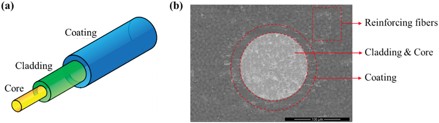
Figure 1: (a) Schematic of an optical fiber; (b) Microscopic structure of composite laminate embedded with optical fiber
Based on the SEM image, plain strain finite element models of the composite laminate embedded with one optical fiber are constructed, as shown in Fig. 2, by using representative volume elements (RVEs) of the material with varying sizes. Given that the core and cladding of the optical fiber are made of the same material, they are treated as a single component in the model. The optical fiber is positioned at the center of the RVEs. The core and cladding together have a diameter of 125 μm, while the overall diameter of the optical fiber is 160 μm. The random distribution of the reinforcing fibers is generated using the random sequential expansion (RSE) algorithm [28] proposed by the author. Firstly, an RVE model of a specific size is generated using the RSE algorithm. Then, the optical fiber is positioned at the center of the model, and the fibers that overlap with it are removed, resulting in an RVE with an embedded optical fiber. Since the size of the optical fiber is fixed, the size of the RVE reflects the density of optical fibers embedded in the composite. In this study, an RVE with dimensions of 300 μm × 300 μm is used to simulate a highly dense embedding of optical fibers. For a relatively sparse embedding of optical fibers, RVEs with dimensions of 600 μm × 600 μm and 1000 μm × 1000 μm are used. Once the RVE size is determined, the number of fibers in the model can be determined according to the fiber volume fraction. Fig. 2 displays the three distinct RVEs with different sizes but same fiber volume fraction of 50%, which respectively contains 431, 2498, and 7377 reinforcing fibers with a diameter of 10 μm. To study the influence of the embedded optical fiber, another three RVEs without optical fiber are also constructed for comparison.
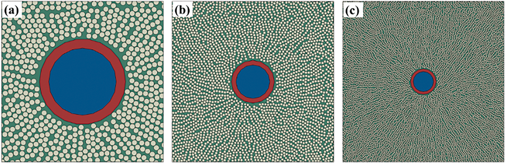
Figure 2: Finite element models of composite laminate imbedded with optical fiber: (a) RVE-1; (b) RVE-2; (c) RVE-3
The finite element models of the RVEs are established by using software ABAQUS. The reinforcing fibers, matrix, and optical fiber are discretized by mainly 4-node bilinear plane strain reduction integration elements (CPE4R) and a few 3-node triangle elements (CPE3). At the same time, 4-node 2D cohesive elements (COH2D4) with zero thickness are inserted not only between reinforcing fibers and the matrix but also between the optical fiber and the matrix to simulate the interface behavior. The number of nodes at the RVE boundary is adjusted to be consistent so that the periodic boundary conditions can be applied. Transverse tensile and transverse compressive loads are applied to the RVEs respectively to analyze their mechanical responses. An analysis of the mesh convergence was carried out, with element sizes of 1, 0.9, 0.8, and 0.5 μm selected for separate calculations. The computational results indicate that there is little difference between the outcomes of varying mesh sizes; however, reducing the mesh size significantly increases the computation time. Therefore, a mesh size of 1 μm is used in this study.
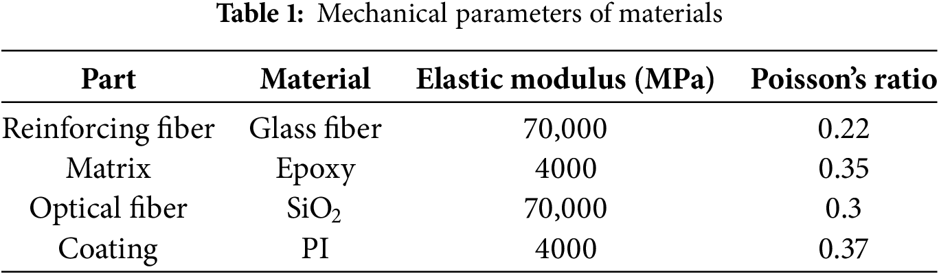
The material composition of the model and corresponding elastic parameters are listed in Table 1. Since damage is unlikely to occur in the reinforcing fibers and the optical fiber under transverse loading, they are modeled as linear elastic materials. However, for the matrix and the interfaces, it is crucial to accurately describe the damage and failure behavior to ensure a realistic representation of the material’s mechanical response under load.
For the epoxy resin, whose behavior is sensitive to the hydrostatic stress, its yield behavior is described by the extended linear Drucker-Prager criterion [29]:
The yield criterion incorporates the hydrostatic stress (p), Mises equivalent stress (q), and the third deviatoric stress invariant (r). The linear yield surface slope in the p–t stress plane is denoted by β, while d represents material cohesion. Additionally, k accounts for differing yield responses under tension and compression by defining the ratio of triaxial tensile yield stress to triaxial compressive yield stress.
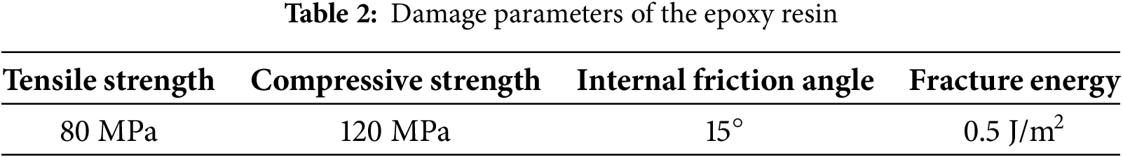
Material failure initiation is determined using a ductile fracture criterion, with the critical plastic strain dependent on stress triaxiality conditions. Post-initiation, damage development follows a progressive failure model. The primary damage effects include yield stress reduction and elastic property deterioration, both regulated by an evolving damage parameter that increases with accumulated material degradation. For further details on the epoxy material model, please refer to our previous publication [29]. The specific damage parameters for the epoxy resin are provided in Table 2.
In addition to the matrix, composite material failure is strongly affected by interface mechanics. The cohesive model is applied here to simulate interfacial behavior, linking the traction vector to the displacement difference across the element’s surfaces. The bilinear constitutive model is employed to capture the stress-displacement relationship of the interface.
In the linear stage, the stress-strain relationship of the interface is given by [29]:
where,
where,
where,
Taking the 300 μm RVE-1 as an example, Fig. 3a illustrates the distribution of the maximum principal stress prior to damage occurrence under transverse tensile loading. The analysis reveals that high-stress regions predominantly form within the reinforcing fibers, while the optical fiber and matrix exhibit relatively low stress levels. Notably, strip-shaped stress concentration areas develop in the reinforcing fibers that are closely aligned in the transverse direction. The presence of optical fibers in the composite material does not significantly alter the stress distribution in the regions outside the optical fiber. However, it is observed that the optical fiber itself experiences varying stress levels, with the coating exhibiting much lower stress compared to the core and cladding. This difference is particularly pronounced at the two poles of the optical fiber, which are oriented perpendicular to the loading direction.
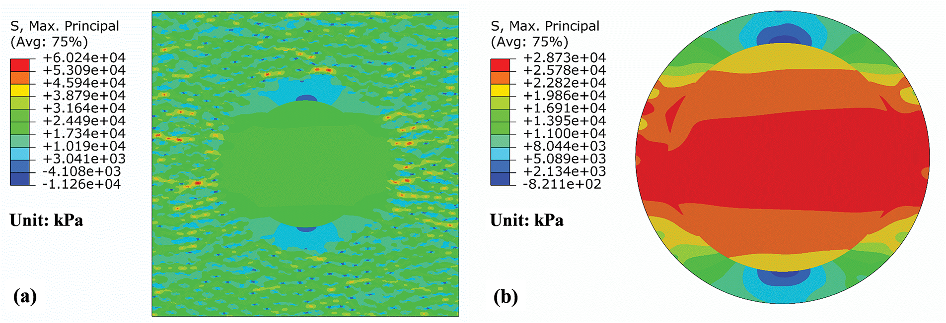
Figure 3: Maximum principal stress distribution of RVE-1 under transverse tensile load: (a) the whole model; (b) the optical fiber
Fig. 3b reveals that interfacial stresses between the fiber coating and matrix have attained critical failure values, initiating debonding as the primary damage mechanism. This interfacial separation progressively propagates along the fiber periphery, as shown in Fig. 4a. Subsequent loading induces similar debonding at reinforcement fiber-matrix interfaces while simultaneously generating matrix microcracks, particularly in regions of high fiber density. These damage modes coalesce, with matrix cracks linking adjacent debonded interfaces to form macroscopic fracture paths. The final failure occurs through crack network merging, creating a dominant fracture plane that traverses the RVE. Contrastingly, Fig. 4b demonstrates that specimens without optical fibers exhibit randomized damage initiation at reinforcement fiber interfaces, followed by less organized crack propagation patterns.
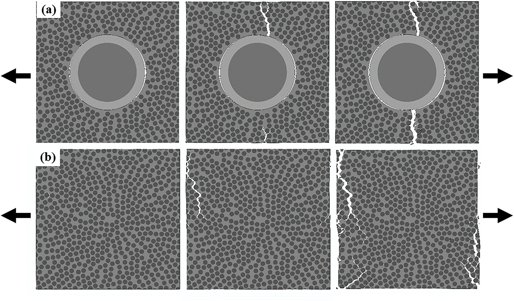
Figure 4: Damage initiation and propagation process of composites under transverse tensile load: (a) with embedded optical fiber; (b) without optical fiber
When larger RVEs are considered, as shown in Fig. 5a,b, in addition to the primary crack that connects to the optical fiber, numerous smaller cracks form in areas further away from the optical fiber. The distribution of these smaller cracks is highly random, which can be attributed to the relatively small impact of the optical fiber has on those regions. Fig. 5c illustrates the actual fracture morphology of a composite laminate with an embedded optical fiber subjected to transverse tension. As observed, the primary crack forms around the optical fiber and leads to fracture, which closely aligns with the simulation results. This suggests that the embedded optical fiber significantly influences the micro-damage behavior of the composite material under transverse tension. The similarity between the real fracture morphology and the simulation outcomes validates the accuracy of the simulation model.
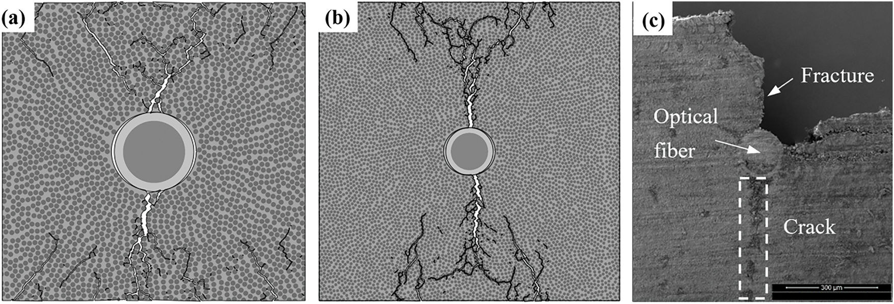
Figure 5: Final damage morphologies under transverse tensile load: (a) RVE-2; (b) RVE-3; (c) SEM image
Fig. 6 presents the transverse tensile behavior of three representative volume elements (RVE-1 to RVE-3). The comparative analysis reveals RVE-1 demonstrates the lowest mechanical performance in both fracture strain and tensile strength, while RVE-3 shows superior properties. These results clearly establish a correlation between fiber distribution density and composite mechanical characteristics. Sparse fiber arrangements yield properties approaching neat resin values, suggesting minimal fiber reinforcement effect, with matrix cracking governing failure. In contrast, dense fiber configurations significantly alter stress transfer mechanisms, leading to pronounced interface effects and substantially reduced tensile strength compared to the pure matrix.
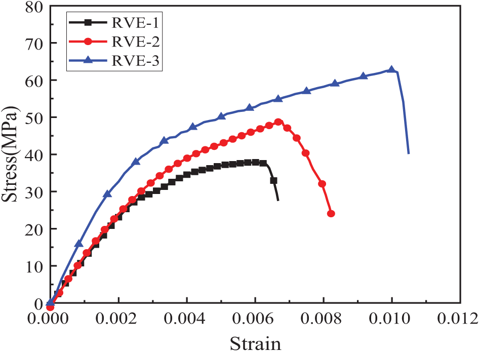
Figure 6: Stress-strain curves of three RVEs under transverse tensile load
Taking the 300 μm RVE-1 as an example, Fig. 7a illustrates the distribution of the maximum principal stress prior to damage occurrence under transverse compressive loading. Similar to the case of transverse tensile loading, high-stress regions are still predominantly formed within the reinforcing fibers, while the optical fiber and matrix exhibit relatively low stress levels. However, under compressive loading, the stress direction in the strip-shaped stress concentration region is perpendicular to the loading direction. The presence of the optical fiber still does not significantly alter the stress distribution in the regions outside the optical fiber. At this point, the stress at the interface between the optical fiber coating and the matrix has reached its failure strength, but the critical stress locations shift to the upper and lower poles of the optical fiber, as shown in Fig. 7b.
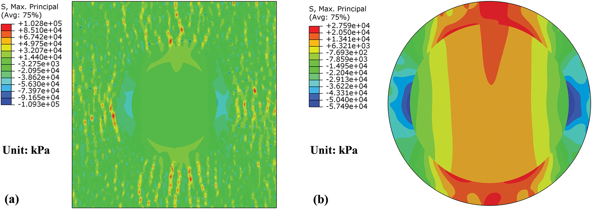
Figure 7: Maximum principal stress distribution of RVE-1 under transverse compressive load: (a) the whole model; (b) the optical fiber
As shown in Fig. 8a, debonding initiates in these two regions, marking the onset of material damage and failure. At the same time, several random cracks also form in the matrix. As the load continues to increase, the matrix cracks on both sides of the optical fiber extend and evolve into two plastic shear bands, which are nearly parallel to each other. Eventually, these matrix shear bands connect with the debonding damages at the optical fiber interface, resulting in the complete fracture and failure of the RVE. For comparison, Fig. 8b illustrates the damage initiation and propagation process of the RVE without embedded optical fibers. In this scenario, a complete plastic shear band develops within the matrix, which leads to the eventual fracture of the RVE. Unlike the case with embedded optical fibers, where the failure initiates at the optical fiber interface, the damage here is more uniform, with the shear band playing a dominant role in the material’s fracture mechanism. This highlights the influence of embedded optical fibers on the failure behavior of composite materials.
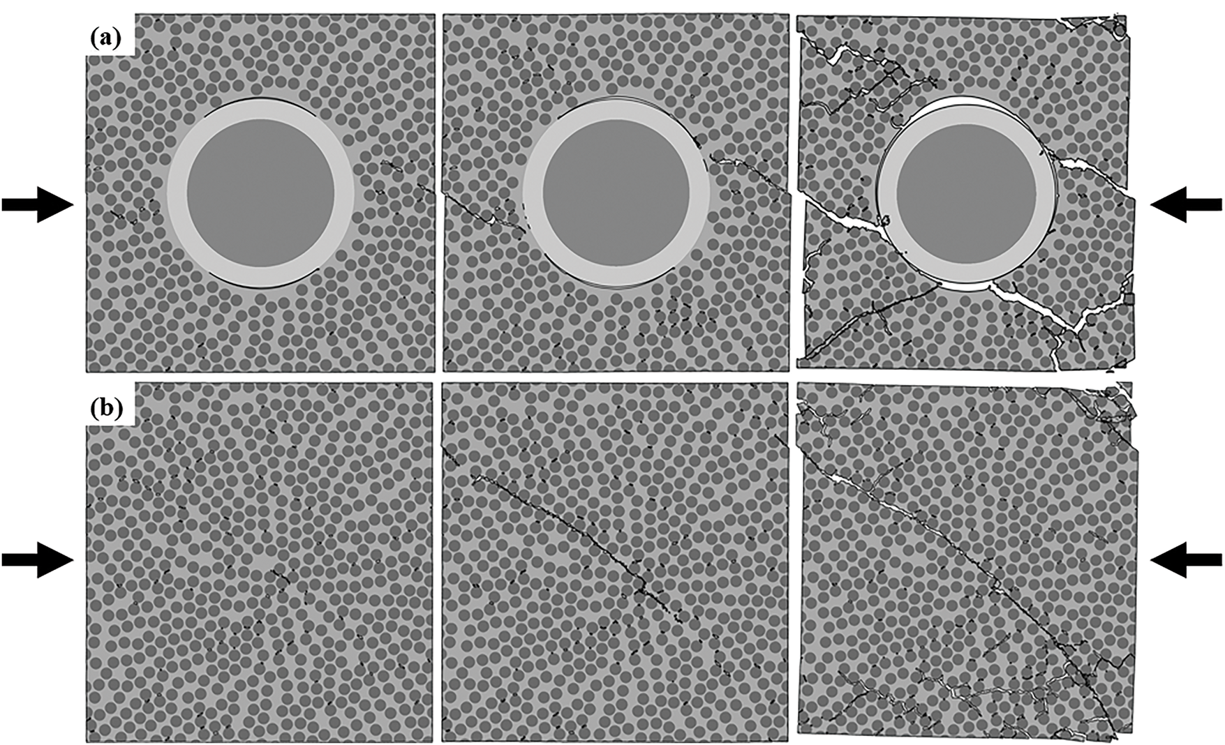
Figure 8: Damage initiation and propagation process of composites under transverse compressive load: (a) with embedded optical fiber; (b) without optical fiber
Fig. 9a,b illustrates the final damage morphologies of RVE-2 and RVE-3 under transverse compressive load. The observed damage patterns are similar with those seen in RVE-1, where the failure is dominated by the connection of matrix shear bands and interface debonding between the optical fiber and matrix. Fig. 9c shows the real fracture morphology of a composite laminate with an embedded optical fiber under transverse compression. Two parallel cracks are observed around the optical fiber, which connect with the debonding at the optical fiber-matrix interface. This aligns closely with the simulation results, confirming the significant role of the embedded optical fiber in altering the micro-damage and failure mechanisms of the composite material under transverse compressive loads.
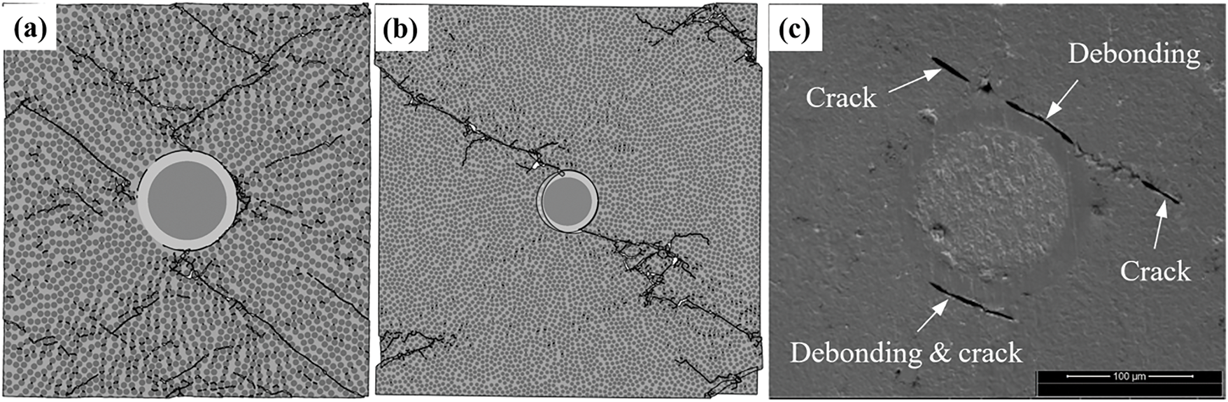
Figure 9: Final damage morphologies under transverse compressive load: (a) RVE-2; (b) RVE-3; (c) SEM image
Fig. 10 depicts the stress-strain curves for RVE-1, RVE-2 and RVE-3 under transverse compressive load. Under compressive loading, the material exhibits behavior analogous to transverse tension: sparse fiber distribution yields compressive strength comparable to the pure matrix, while dense fiber arrangements result in reduced overall strength.
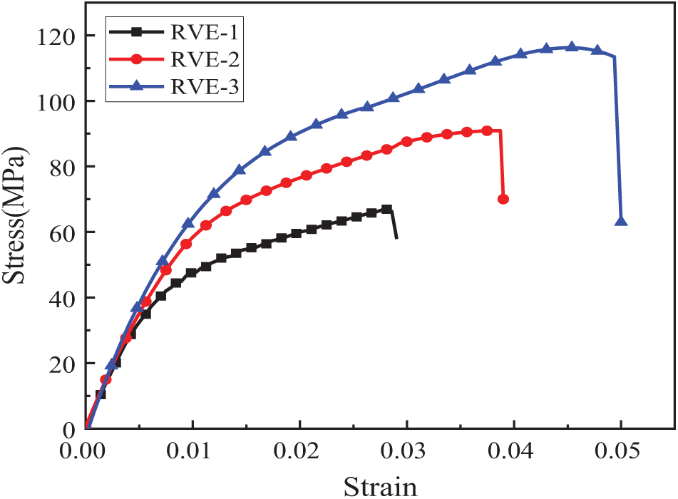
Figure 10: Stress-strain curves of three RVEs under transverse compressive load
3.3. Influence of Interface Parameters
The selection of material parameters, particularly interface parameters, is essential in accurately simulating the micro-damage mechanisms in composite materials. Among these, the interface strength between the optical fiber and the matrix plays a crucial role in determining the damage initiation and evolution. Since it is challenging to experimentally measure the interface strength between the optical fiber and the matrix, and considering that different optical fiber coatings can significantly affect this strength, numerical simulation becomes a key tool for exploring its effects.
In this study, we investigate how variations in interface strength impact the micro-failure mechanisms of the composite materials. By setting different values for the interface strength in the simulations, we can assess how changes in this parameter influence damage initiation, crack propagation, and overall material failure. The findings demonstrate that selecting proper interface strength parameters is crucial for realistically simulating fiber-matrix interactions and predicting composite damage responses under various loading scenarios. This investigation yields significant understanding of how fiber-matrix interfacial properties influence composite microstructural stability, providing critical information for material optimization and improving the performance reliability of smart composites with embedded optical fibers.
Taking RVE-1 under transverse tensile load as an example, we analyze the effect of different interface strengths between the optical fiber and the matrix on the failure morphology of the RVE. The interface strengths selected for the study are 27, 50, and 100 MPa, respectively. The final failure morphologies obtained are shown in Fig. 11. It can be observed that for interface strengths of 27 and 50 MPa, the material’s final damage morphology is similar, with a primary crack forming along the interface of the optical fiber. This is due to the relatively lower interface strength, which results in interface debonding being the dominant damage mechanism. The optical fiber plays a significant role in initiating the damage by concentrating stress at the optical fiber-matrix interface. However, at a higher interface strength of 100 MPa, the damage behavior changes. The crack appears at the boundary of the RVE, far from the optical fiber, and the material does not fracture around the optical fiber. In this case, the stress intensity near the optical fiber is not high enough to cause interface debonding, and instead, the matrix material surrounding the fiber fails first. This shift in damage mechanism indicates that when the interface strength between the optical fiber and the matrix is relatively high, the presence of the embedded fiber has a diminished impact on the material’s micro-damage behavior. The matrix itself becomes the primary source of failure, and the role of the optical fiber in stress concentration and damage initiation is reduced.
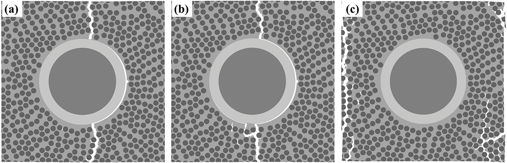
Figure 11: Damage morphologies of RVE-1 with different optical fiber-matrix interface strengths: (a) 27 MPa; (b) 50 MPa; (c) 100 MPa
The stress-strain curves of the RVE under tensile load, as shown in Fig. 12, clearly demonstrate the relationship between optical fiber-matrix interface strength and the mechanical behavior of the composite material. When interface strength is low, the failure is dominated by the debonding at the optical fiber-matrix interface. The interface debonding leads to earlier failure as the stress concentrates around the optical fiber. Consequently, the material fractures at lower stresses and higher strains due to the early onset of interface failure. As the interface strength increases to 100 MPa, the tensile strength of the material increases significantly. This is because the stronger bond between the optical fiber and matrix resists debonding, allowing the matrix to bear more load before failure. However, the fracture strain decreases as the failure mechanism shifts from interface debonding to matrix cracking. In this case, the matrix cracks first, and the optical fiber contributes to strengthening the material. As a result, the structure’s mechanical properties are enhanced, and the tensile strength approaches that of the material without embedded optical fibers.
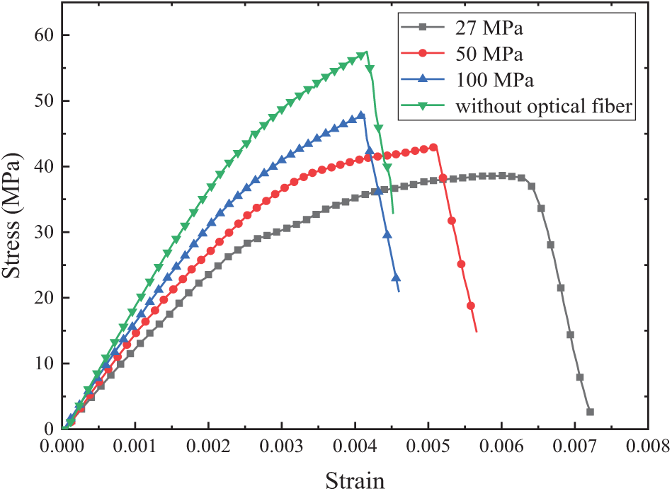
Figure 12: Stress-strain curves of RVE-1 under tensile load with different optical fiber-matrix interface strengths
3.4 Influence of Fiber Volume Fraction
The fiber volume fraction typically has a certain influence on the mechanical properties of composites. To investigate the effect of fiber volume fraction on the micro-damage process of composites embedded with optical fibers, RVEs with fiber volume fractions of 50%, 55% and 60% were generated to simulate the damage and failure process under transverse tensile loading. The results are shown in Fig. 13.
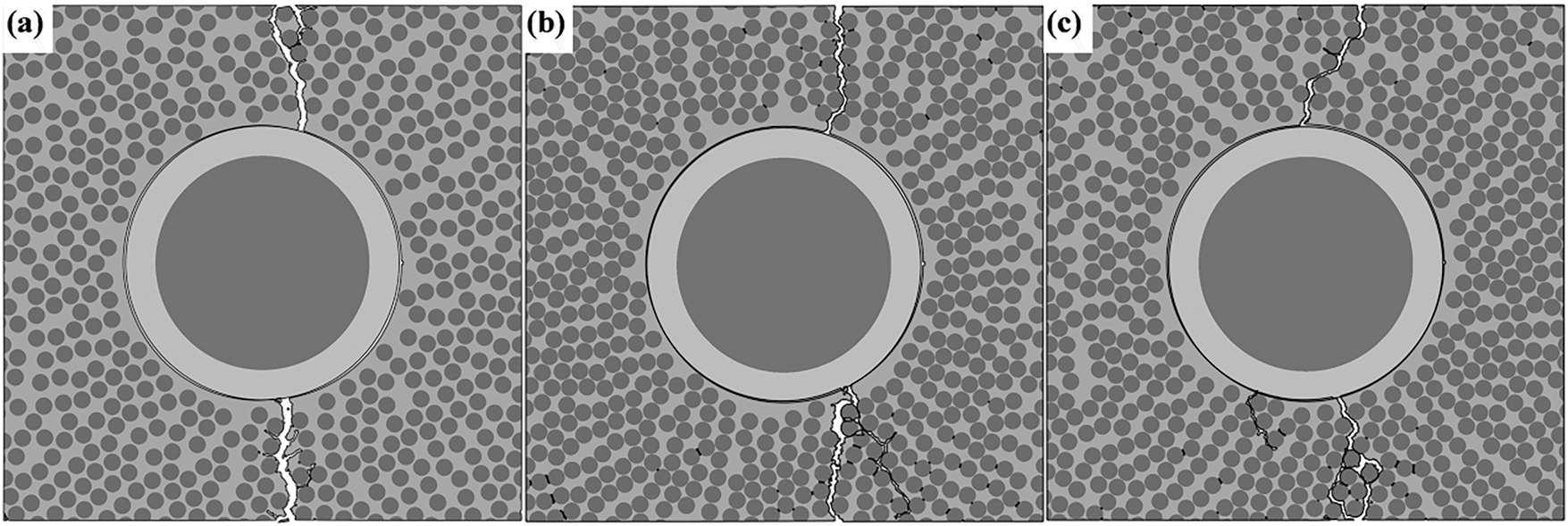
Figure 13: Damage morphologies of RVEs with different fiber volume fractions: (a) 50%; (b) 55%; (c) 60%
From the figure, it is observed that different fiber volume fractions do not significantly alter the mechanism of damage and failure. However, a higher fiber volume fraction leads to an increase in the number of microcracks within the RVE, due to smaller gaps between fibers, which facilitates matrix cracking. Additionally, the findings of this part of the study also demonstrate the reliability of the results obtained using the model with a specific fiber volume fraction selected in this paper.
This paper adopts a micromechanical approach to investigate the influence of embedded optical fibers on the mechanical and failure behavior of composite materials. Representative Volume Elements (RVEs) of different sizes were constructed, and then transverse tensile and compressive loads were applied to these RVEs to study the micro-damage mechanisms and failure processes.
The results show that under transverse tensile loading, the interface between the optical fiber coating and the matrix first reaches its failure strength, leading to debonding at the interface and the formation of curved cracks. Then the surrounding matrix gradually fractures as well. Eventually, the microcracks caused by matrix fracture connect with the cracks formed by interface debonding, penetrating the RVE and causing material failure. Under transverse compressive loading, the damage also initiates in the optical fiber-matrix interface, but in a direction perpendicular to the load, and plastic cracks form in the matrix around the optical fiber. As the compressive load increases, the debonding area and matrix cracks expand, forming two parallel shear bands that ultimately lead to the failure of the RVE.
The investigation utilized representative volume elements (RVEs) of varying dimensions to simulate different optical fiber distributions. Computational results demonstrate that fiber density variations minimally impact the material’s final failure mode. Experimental characterization of post-loading microstructures corroborated these findings, confirming the model’s validity.
Furthermore, parametric studies of fiber-matrix interfacial properties showed substantial influence on mechanical response. Enhanced interface strength was found to improve tensile strength but reduce fracture strain. Beyond a critical interfacial strength threshold, stress concentrations near fibers became insufficient to initiate debonding, shifting the failure mechanism to matrix-dominated fracture.
In addition to the research content addressed in this paper, future studies could delve deeper into the following aspects. Investigate the mechanisms of material damage and failure after embedding optical fibers in composite materials along different directions, and develop a multiscale mechanical model for composite laminates with embedded optical fibers. Moreover, the laminates could employ various stacking angles to reveal the mechanisms of material damage and failure under different loading conditions. Additionally, explore the mechanical properties of composite materials with embedded optical fibers under fatigue, impact, and other types of loading, and test the survivability of the optical fiber sensors inside the materials to explore the application prospects of this material under more complex working conditions.
Acknowledgement: This paper is a collaborative effort of the five authors. We would like to express our gratitude for the fund support provided by the relevant project and thank all the experts who participated in the review process.
Funding Statement: This research was funded by the National Key Research and Development Program of China (Grant No. 2022YFB3402500), and the National Natural Science Foundation of China (Grant No. 12372129).
Author Contributions: Lei Yang: Writing—review & editing, Supervision, Funding acquisition, Conceptualization; Jianfeng Wang: Writing—original draft, Investigation, Methodology; Minjing Liu: Validation, Formal analysis; Chunyu Chen: Validation, Formal analysis; Zhanjun Wu: Resources, Conceptualization. All authors reviewed the results and approved the final version of the manuscript.
Availability of Data and Materials: The data that support the findings of this study are available from the corresponding author upon reasonable request.
Ethics Approval: Not applicable.
Conflicts of Interest: The authors declare no conflicts of interest to report regarding the present study.
References
1. Grogan DM, Ó Brádaigh CM, McGarry JP, Leen SB. Damage and permeability in tape-laid thermoplastic composite cryogenic tanks. Compos Part A Appl Sci Manuf. 2015;78:390–402. doi:10.1016/j.compositesa.2015.08.037. [Google Scholar] [CrossRef]
2. Yang H, Zhou Z, Ou J. A novel smart steel strand based on optical-electrical co-sensing for full-process and full-scale monitoring of prestressing concrete structures. Int J Smart Nano Mater. 2023;14:337–68. doi:10.1080/19475411.2023.2237940. [Google Scholar] [CrossRef]
3. Zhu C, Zhuang Y, Liu B, Huang J. Review of fiber optic displacement sensors. IEEE Trans Instrum Meas. 2022;71:1–12. doi:10.1109/tim.2022.3188510. [Google Scholar] [CrossRef]
4. Floris I, Adam JM, Calderón PA, Sales S. Fiber optic shape sensors: a comprehensive review. Opt Lasers Eng. 2021;139:106508. doi:10.1016/j.optlaseng.2020.106508. [Google Scholar] [CrossRef]
5. Hong C, Zhang Y, Zhang M, Leung LMG, Liu L. Application of FBG sensors for geotechnical health monitoring, a review of sensor design, implementation methods and packaging techniques. Sens Actuators A Phys. 2016;244(15):184–97. doi:10.1016/j.sna.2016.04.033. [Google Scholar] [CrossRef]
6. Jiang T, Ren L, Jia Z, Li D, Li H. Application of FBG based sensor in pipeline safety monitoring. Appl Sci. 2017;7(6):540. doi:10.3390/app7060540. [Google Scholar] [CrossRef]
7. Wang S, Yang Z, Mohanty L, Zhao C, Han C, Li B, et al. Distributed fiber optic sensing for internal strain monitoring in full life cycle of concrete slabs with BOFDA technology. Eng Struct. 2024;305(15):117798. doi:10.1016/j.engstruct.2024.117798. [Google Scholar] [CrossRef]
8. Tian C, Ma X, Peng B, Ma X, Li Z. Measurement-error analysis of fiber bragg grating flexible sensor for displacement-field monitoring of geotechnical engineering. Sensors. 2022;22(19):7168. doi:10.3390/s22197168. [Google Scholar] [PubMed] [CrossRef]
9. Jothibasu S, Du Y, Anandan S, Dhaliwal GS, Gerald RE, Watkins SE, et al. Spatially continuous strain monitoring using distributed fiber optic sensors embedded in carbon fiber composites. Opt Eng. 2019;58(7):072004. doi:10.1117/1.oe.58.7.072004. [Google Scholar] [CrossRef]
10. Xiao Y, Rans C, Zarouchas D, Benedictus R. A comprehensive study on measurement accuracy of distributed fiber optic sensors embedded within capillaries of solid structures. Sensors. 2023;23(19):8083. doi:10.3390/s23198083. [Google Scholar] [PubMed] [CrossRef]
11. Zhuang Y, Yang Q, Han T, O’Malley R, Kumar A, Gerald RE, et al. Fiber optic sensor embedded smart helmet for real-time impact sensing and analysis through machine learning. J Neurosci Methods. 2021;351(1):109073. doi:10.1016/j.jneumeth.2021.109073. [Google Scholar] [PubMed] [CrossRef]
12. Biondi AM, Guo X, Wu R, Cao L, Zhou J, Tang Q, et al. Smart textile embedded with distributed fiber optic sensors for railway bridge long term monitoring. Opt Fiber Technol. 2023;80:103382. doi:10.1016/j.yofte.2023.103382. [Google Scholar] [CrossRef]
13. Ramakrishnan M, Rajan G, Semenova Y, Boczkowska A, Domański A, Wolinski T, et al. Measurement of thermal elongation induced strain of a composite material using a polarization maintaining photonic crystal fiber sensor. Sens Actuators A Phys. 2012;190(1):44–51. doi:10.1016/j.sna.2012.11.010. [Google Scholar] [CrossRef]
14. Drissi-Habti M, Raman V, Khadour A, Timorian S. Fiber optic sensor embedment study for multi-parameter strain sensing. Sensors. 2017;17(4):667. doi:10.3390/s17040667. [Google Scholar] [PubMed] [CrossRef]
15. Al-Shawk A, Tanabi H, Sabuncuoglu B. Investigation of stress distributions in the resin rich region and failure behavior in glass fiber composites with microvascular channels under tensile loading. Compos Struct. 2018;192(15):101–14. doi:10.1016/j.compstruct.2018.02.061. [Google Scholar] [CrossRef]
16. Fikry MJM, Vinogradov V, Ogihara S. Experimental observation and modeling of resin pocket cracking in unidirectional laminates with ply discontinuity. Compos Sci Technol. 2021;218(8):109175. doi:10.1016/j.compscitech.2021.109175. [Google Scholar] [CrossRef]
17. Soleymani M, Tahani M, Zamani P. On the influence of resin pocket area on the failure of tapered sandwich composites. Adv Struct Eng. 2021;24(1):42–51. doi:10.1177/1369433220940816. [Google Scholar] [CrossRef]
18. Etches JA, Fernando GF. Evaluation of embedded optical fiber sensors in composites: EFPI sensor response to fatigue loading. Polym Compos. 2010;31(2):284–91. doi:10.1002/pc.20801. [Google Scholar] [CrossRef]
19. Etches JA, Fernando GF. Evaluation of embedded optical fiber sensors in composites: EFPI sensor fabrication and quasi-static evaluation. Polym Compos. 2009;30(9):1265–74. doi:10.1002/pc.20690. [Google Scholar] [CrossRef]
20. Hadzic R, John S, Herszberg I. Structural integrity analysis of embedded optical fibres in composite structures. Compos Struct. 1999;47(1):759–65. doi:10.1016/s0263-8223(00)00050-7. [Google Scholar] [CrossRef]
21. Abidin DZ, Theminimulla S, Waugh DG, Griffin JM. Optical fibers in composite materials: the effects on mechanical properties under flexural and tensile loading and acoustic emission monitoring. Proc Inst Mech Eng Part C J Mech Eng Sci. 2022;236(16):9169–85. doi:10.1177/09544062221092352. [Google Scholar] [CrossRef]
22. Shivakumar K, Emmanwori L. Mechanics of failure of composite laminates with an embedded fiber optic sensor. J Compos Mater. 2004;38(8):669–80. doi:10.1177/0021998304042393. [Google Scholar] [CrossRef]
23. Shivakumar K, Bhargava A. Failure mechanics of a composite laminate embedded with a fiber optic sensor. J Compos Mater. 2005;39(9):777–98. doi:10.1177/0021998305048156. [Google Scholar] [CrossRef]
24. Eaton NC, Drew RC, Geiger H. Finite element stress and strain analysis in composites with embedded optical fiber sensors. Smart Mater Struct. 1995;4(2):113–7. doi:10.1088/0964-1726/4/2/007. [Google Scholar] [CrossRef]
25. Korepanov VV, Serovaev GS, Yurlova NA. Numerical modelling of layered composite materials with embedded optical fiber sensors. Solid State Phenom. 2015;243:83–8. doi:10.4028/www.scientific.net/SSP.243.83. [Google Scholar] [CrossRef]
26. Fedorov AY, Kosheleva NA, Matveenko VP, Serovaev GS. Strain measurement and stress analysis in the vicinity of a Fiber Bragg grating sensor embedded in a composite material. Compos Struct. 2020;239:111844. doi:10.1016/j.compstruct.2019.111844. [Google Scholar] [CrossRef]
27. Cai L, Wang XC. Optical fiber refractive index sensor based on the double cladding fiber. Instrum Sci Technol. 2021;50(4):414–21. doi:10.1080/10739149.2021.2018602. [Google Scholar] [CrossRef]
28. Yang L, Yan Y, Ran Z, Liu Y. A new method for generating random fibre distributions for fibre reinforced composites. Compos Sci Technol. 2013;76:14–20. doi:10.1016/j.compscitech.2012.12.001. [Google Scholar] [CrossRef]
29. Yang L, Yan Y, Liu Y, Ran Z. Microscopic failure mechanisms of fiber-reinforced polymer composites under transverse tension and compression. Compos Sci Technol. 2012;72(15):1818–25. doi:10.1016/j.compscitech.2012.08.001. [Google Scholar] [CrossRef]
30. Kyriazis A, Kilian R, Sinapius M, Rager K, Dietzel A. Tensile strength and structure of the interface between a room-curing epoxy resin and thermoplastic films for the purpose of sensor integration. Polymers. 2021;13:330. doi:10.3390/POLYM13030330. [Google Scholar] [PubMed] [CrossRef]
Cite This Article
 Copyright © 2025 The Author(s). Published by Tech Science Press.
This work is licensed under a Creative Commons Attribution 4.0 International License , which permits unrestricted use, distribution, and reproduction in any medium, provided the original work is properly cited.
 Downloads
 Citation Tools